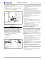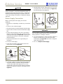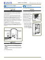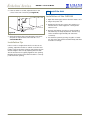
1
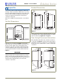
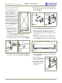
™
Installation Guide
CLR2060 — Clear Ice Maker
www.U-LineService.com
Phone (414) 354-0300 • FAX (414) 354-7905
Service & Parts Tech Lines Phone (800) 779-2547 • FAX (414) 354-5696
[email protected]
©2005 U-Line Corporation
02/2005
™
CLR2060 — Clear Ice Maker
Contents
Cut-Out Dimensions . . . . . . . . . . . . . . . . . . . . . . . . . . .
Product Dimensions . . . . . . . . . . . . . . . . . . . . . . . . . . . .
Door Swing/Clearances Information . . . . . . . . . . . . . .
Reversing the Door. . . . . . . . . . . . . . . . . . . . . . . . . . . . .
Other Site Requirements . . . . . . . . . . . . . . . . . . . . . . . .
Side-By-Side Installation Instructions . . . . . . . . . . . . . .
Custom 1/4'' Door Panel Insert . . . . . . . . . . . . . . . . . . .
Full Overlay Door Panel . . . . . . . . . . . . . . . . . . . . . . . . .
Checking Door Alignment . . . . . . . . . . . . . . . . . . . . . .
Adjusting Door Alignment . . . . . . . . . . . . . . . . . . . . . .
Drain Connection . . . . . . . . . . . . . . . . . . . . . . . . . . . . . .
Water Supply Connection . . . . . . . . . . . . . . . . . . . . . . .
Electrical Specifications . . . . . . . . . . . . . . . . . . . . . . . . .
Leveling Information . . . . . . . . . . . . . . . . . . . . . . . . . . .
Installation Tip . . . . . . . . . . . . . . . . . . . . . . . . . . . . . . . .
Installation of the CLR2060 . . . . . . . . . . . . . . . . . . . . . .
Installation Troubleshooting . . . . . . . . . . . . . . . . . . . . .
Initial Start-Up . . . . . . . . . . . . . . . . . . . . . . . . . . . . . . . .
Start-Up Troubleshooting . . . . . . . . . . . . . . . . . . . . . . .
Service Information . . . . . . . . . . . . . . . . . . . . . . . . . . . .
1 Follow Safety Precautions
4
4
4
5
6
6
7
8
11
11
12
15
16
16
17
17
18
18
19
20
IMPORTANT
PLEASE READ all instructions completely before
attempting to install or operate the unit.
• This unit requires connection to the water supply.
Improper hook-up can result in substantial property
damage! If you are unsure of your ability to safely
connect the water supply to the unit, consult a licensed
plumber for assistance.
• This unit requires connection to a drain. Improper
connection can result in substantial property damage!
If you are unsure of your ability to safely connect the
unit to a drain, consult a licensed plumber for
assistance.
• This unit requires connection to a grounded (threeprong), polarized receptacle that has been placed by a
qualified electrician in accordance with applicable
electrical codes.
Safety Alert Definitions
Safety items throughout this guide are labeled with a
Danger, Warning or Caution based on the risk type:
DANGER
Danger means that failure to follow this safety
statement will result in severe personal injury or
death.
WARNING
Warning means that failure to follow this safety
statement could result in serious personal injury,
or death.
CAUTION
Caution means that failure to follow this safety statement
may result in minor or moderate personal injury, property
or equipment damage.
www.U-LineService.com
2
02/2005
™
CLR2060 — Clear Ice Maker
General Precautions
2 Inspect and Plan
Use this appliance for its intended purpose only and
follow these general precautions along with those listed
throughout this guide:
You have received a carton containing your CLR2060 Clear
Ice Maker with a package inside containing a User Manual,
a Product Registration Card and water connection parts.
Complete and mail the Product Registration Card or
register online at www.U-LineService.com. Once your unit
is installed, keep the User Manual and this Installation
Guide in a safe place for future reference.
WARNING
SHOCK HAZARD — Electrical Grounding Required.
• Keep the unit unplugged throughout installation
except during testing.
Your unit is Black, White or Stainless Steel. Black and
White units have a reversible door with a slightly
contoured handle across the top. They come with a flush
mounted door panel that, when removed, will accept a
custom 1/4-inch thick door panel or a 3/4-inch thick full
overlay door panel. Stainless Steel units are covered with
a protective coating and have been ordered left- or righthand hinged. The Stainless doors are not reversible and
do not accept custom panels. CLR2060 Clear Ice Makers
may be ordered with a factory-installed drain pump.
Please carefully follow the directions that apply to your
unit and your intended design.
• Never remove the round grounding prong from
the plug and never use a two-prong grounding
adapter.
• Never use an extension cord to connect power to
the unit.
• Always keep your working area dry.
CAUTION
• Use care when moving and handling the unit. Use
gloves to prevent personal injury from sharp edges.
• Do not lift the unit by the door or door handle.
Tools/Materials Required
• Do not install the unit behind closed doors or in any
way that would obstruct airflow to the front grille,
which may cause the unit to malfunction.
• 7/64" Allen wrench
• Screwdrivers — slotted and Phillips head
• 1/4-inch OD copper tubing and shut-off valve for water
supply line
• 5/8-inch ID drain line
• P60 Drain Pump (if required and not already factory
installed, see Page 12)
• 1/4-inch thick door panel material and cutting tools
(Black or White units)
• Full Overlay Door Panel Kit (part number U-OL2015B —
Black or part number U-OL2015W — White), 3/4-inch
door panel overlay, cutting tools, drill and bits (Black or
White units)
Inspection
Unwrap and inspect the unit on a flat, level surface
capable of supporting its entire weight.
02/2005
3
www.U-LineService.com
™
CLR2060 — Clear Ice Maker
Product Dimensions
3 Prepare Site
24"
Including
Handle
Your U-Line product has been designed for either freestanding or built-in installation. When built-in, your unit
does not require additional air space for top, sides or rear.
However, the front grille must NOT be obstructed and
clearance is required for water, drain and electrical
connections in the rear.
26-1/8"
Including
Handle
Note: Unit can NOT be installed behind a closed cabinet
door.
Cut-Out Dimensions
34-1/8"
34-1/8"
14-15/16"
Stainless Steel
14-15/16"
Black and White
See Electrical
Specifications
for Power Supply
Figure 2
24"
34-1/4"
to
35-1/8"
Please note that the unit has adjustable feet that can add
one additional inch to height during leveling or to match
adjacent cabinets (see Figure 44 on Page 17.)
8"
Door Swing/Clearances Information
15-3/16"
Black and White units have a zero clearance for the door
to open 90° (see Figure 3). Stainless Steel models require
a minimum of 2-1/8" door clearance to accommodate the
handle if the unit is installed next to a wall or similar type
of structure.
Figure 1
Follow the cut-out drawing in Figure 1. The 15-3/16"
width allows 1/4" for ease in installation and removal of
the unit. The 24" depth is the counter depth in most
installations. The unit is 24" deep including the handle
on Black and White models and 24" deep including the
door and not the handle on Stainless Steel models (see
Figure 2).
Wall
Wall
1/4" Min.
2-1/8" Min.
IMPORTANT
If you would like to align the face of the unit with other
adjacent cabinet doors in certain installations, you may
need to alter the wall just behind the drain connection on
the unit to accommodate the drain. The actual amount of
alteration will be determined by your actual drain
connection components.
21-3/4"
21-3/4"
16-1/2"
90°
Door Swing
Black and White
16-1/2"
90°
Door Swing
Stainless Steel
Figure 3
www.U-LineService.com
4
02/2005
™
CLR2060 — Clear Ice Maker
Reversing the Door
4. Remove the two door closer inserts from the existing
bottom hinge and install as shown on the new bottom
hinge (see Figure 8).
(Black and White Units Only)
All U-Line units (except
Stainless Steel models) may
be left- or right-hand
opening. The door opening is
easily reversed by moving the
hinge hardware to the
opposite side. The top hinge
hardware will be used on the
bottom of the other side and
the bottom hinge hardware
will be used on the top of the
other side (see Figure 4).
Hinge
Screw
Pin
Door
Closer
Inserts
Figure 7
Figure 8
To reverse the door:
5. Remove existing bottom hinge (3 screws) and remount
on opposite side TOP. Remove hinge screw pin.
1. Remove top hinge screw
pin from door (7/64"
Allen wrench or Phillips
screwdriver, depending
Figure 4
on your unit’s
construction) (see Figure 5). Remove door by tilting
forward and lifting off bottom hinge pin.
6. Remove the plastic hole plug from the top of the door
to allow the pivot pin to be inserted in the new
location. Install the plug into the vacated hole on the
opposite side.
7. With bottom of door facing up, remove pivot plate
(2 screws), flip over, and remount on opposite side of
door (see Figure 9). Be sure notch in plate faces center.
2. Remove plastic screw plugs (3 each, top and bottom)
from new hinge location. Do not discard (see Figure 6).
Screw Plugs
Figure 5
Figure 9
Figure 6
8. Holding door upright with top of door tilted forward,
place hole of door pivot plate on bottom hinge screw
pin (see Figure 10).
3. Remove top hinge (3 screws), reinstall hinge screw pin,
and remount on opposite side BOTTOM (see Figure 7).
9. Tilt top of door into
position in top hinge and
install top hinge screw pin.
10. Install plastic screw plugs
removed in Step 2 in old
hinge holes (3 each, top
and bottom).
Figure 10
02/2005
5
www.U-LineService.com
™
CLR2060 — Clear Ice Maker
Other Site Requirements
Side-By-Side Installation
Instructions
Power Supply
For a complete refreshment center, install your CLR2060
Clear Ice Maker beside a U-line Refrigerator, Combo, or
Wine Captain Model (see Figure 11 for typical cut-out).
Note that each Side-By-Side Installation will be different.
The unit requires a grounded and polarized 115 VAC,
60 Hz, 15A circuit (normal household current). See
Electrical Specifications on Page 16.
Water Supply
• Cut-out width for a side-by-side installation is the total
of the widths listed under Cut-Out Dimensions in each
unit’s Installation Guide.
The unit requires a 1/4-inch OD water supply line and a
shut-off valve. For more information see Page 15.
For example:
Drain
Placing a CLR2060 Clear Ice Maker next to a 2015R
Refrigerator would require a cut-out width of:
15-3/16" + 15-3/16" = 30-3/8"
The unit’s generous 7-inch drain connection height
extends the distance the unit can be located from a
gravity drain. For more information see Page 12.
Placing a CLR2060 Clear Ice Maker next to a 2075R
Refrigerator would require a cut-out width of:
15-3/16" + 24-3/16" = 39-3/8"
IMPORTANT
Drain can NOT be located directly below unit. Unit has a
solid base that will not allow unit to drain below itself.
• No trim kit is required. However, 1/4-inch space needs to
be maintained between the units to ensure
unobstructed door swing.
Environmental Requirements
The surrounding air temperature must be at least 50°F
(10°C) but must not exceed 110°F (40°C). High ambient
temperature ranges and warmer water supply will cause
reduced ice production. Black and White units may be
installed outdoors in a covered area. Stainless Steel
CLR2060 units are deemed suitable for outdoor use by UL.
The unit must not be located near heat-generating
equipment or in direct sunlight.
• Units must operate from separate, properly grounded
electrical receptacles placed according to each unit’s
Electrical Specifications.
Typical Side-By-Side Cut-Out
34-1/4"
to
35-1/8"
Preferred
Location
for CLR2060
Receptacle
Acceptable
Location
24"
7"
1/4" Space
Between Appliances
1"
Figure 11
www.U-LineService.com
6
02/2005
™
CLR2060 — Clear Ice Maker
4 Prepare and Install Door Panel
(Black and White Units Only)
Two types of custom door panels can be installed on your
Black or White unit to harmonize with or accent the
surrounding décor: a Custom 1/4" Insert or a Full Overlay.
If no custom door panel is used, go on to 5 Adjust Door.
Custom 1/4'' Door Panel Insert
Door Panel Preparation
Figure 12
A custom door panel can be inserted into the doorframe.
Custom door panels can be flat or raised, as long as the
maximum panel thickness where inserted into the door
reveal (channel) is 1/4"-thick. For raised panels, the depth
of the reveal is 1/4" on all four sides.
Figure 13
2. Pull door gasket out of groove (top edge of door only).
Start in the middle and pull outward, moving toward
the edge (see Figure 13). This may take some force. Do
not remove the three screws behind gasket.
IMPORTANT
Raised panels will reduce the door’s 90° swing/zero
clearance if the unit is installed next to a wall or similar
type of structure (see Page 4).
3. Remove two outside screws holding door handle.
Slightly separate door handle from door (see
Figure 14).
Cut the panel insert to the following dimensions.
4. Pull handle up and off.
Custom 1/4" Dimensions:
5. Remove and discard
existing panel.
Width:
Height:
14-1/32"
28-5/32"
6. Slide custom door panel
insert into 1/4-inch
channel in door front.
The door panel must not weigh more than 20 lbs.
7. Holding door gasket out
of the way, replace handle
on door, making sure it is
seated properly on insert
and that screw holes
line up.
Door Panel Installation
Install the insert as follows:
CAUTION
Use care when handling the insert. Insert edges may be
sharp.
8. Install two small screws removed in Step 3.
9. Starting at the corners and working inward, push door
gasket into place on door.
1. Remove top hinge screw pin (7/64" Allen wrench or
Phillips screwdriver, depending on your unit’s
construction, see Figure 12). Remove door by tilting
forward and lifting off bottom hinge pin.
02/2005
Figure 14
10. Place door on bottom hinge pin and install upper hinge
screw. Go on to 5 Adjust Door.
7
www.U-LineService.com
™
CLR2060 — Clear Ice Maker
Full Overlay Door Panel
13/32"
0.177" Dia. (#16 Drill)
x 11/16" Deep
Door Panel Preparation
13/32"
3/8"
A full overlay door panel completely covers the
doorframe and handle to give a built-in appearance. See
your U-Line dealer for the optional Full Overlay Door
Panel Kit (P/N U-OL2015B — Black or P/N U-OL2015W —
White). Appropriate hardware, Modified Handle,
Replacement Hinges and a copy of these instructions will
be included in the kit.
3/8"
Door Bottom:
5/16" Dia. x 1/4" Deep
Chamfer 1/32" x 45°
Bottom View
13/16"
Top View
1. Cut the overlay to the following dimensions (see
Figure 15).
1/8"
1/8"
13/32"
Full Overlay Dimensions:
1/32" R
13/16"
Width:
14-3/4"
Height:
29-7/8"
1/8"
1-17/32"
7/16"
The door panel must not weigh more than 20 lbs.
1/8" R
5/16" Dia.
x 1/2" Deep
13/16"
3/4"
3/4"
13/16"
Back View
Side View
Figure 16
1/8"
Route notch in top corner of overlay panel as shown
(see Top and Side Views). Top of notch is entire depth
of panel, front to back.
1/8"
Rear View
of
Wood Panel
Relief Notch
for Pivot Plate
29-7/8"
Width: 13/16"
Depth: 1/8"
Route notch in backside of top corner of overlay panel
(see Back and Side Views).
Width: 13/16"
Depth: 1/8"
14-3/4"
Height: 1-17/32" from top edge of panel (less 1/8" for
depth of notch on top of panel)
Figure 15
Radius of corner notch: 1/8" (see Back View)
IMPORTANT
3. Drill holes for pivot plate mounts (see Figure 16, Back
View).
Rear View of wood panel for right-hand hinge shown. Use
mirror image for left-hand hinges.
5/16" diameter x 1/2" deep, from the routed surface
2. Create a relief (Figure 15) for pivot plate by cutting
notch in top corner and coinciding back corner of
overlay panel. Refer to Figure 16 for exact
specifications.
www.U-LineService.com
CAUTION
Be careful not to drill too deep! Drilling holes too deep
may destroy your door panel.
8
02/2005
™
CLR2060 — Clear Ice Maker
4. Drill hole for upper door hinge (top of panel) (see
Figure 16, Top View).
4. Remove the top handle and discard. (This handle will be
replaced with the Modified Handle included in the Full
Overlay Door Panel Kit.)
0.177" diameter
(#16 drill) x 11/16" deep
5. Remove the two screws located on both sides of the
lower handle. Remove the handle.
5. Drill hole for lower door hinge (see Figure 16, Bottom
View).
6. Attach the Modified Handle to the lower handle using
the three screws removed in Step 3. Set aside.
5/16" diameter x 1/4" deep
7. Slide the existing door panel out of the doorframe.
CAUTION
Attaching the Full Overlay Panel
1. Tap nylon inserts into the top holes drilled in the
overlay panel. Use two #6 screws to attach top pivot
bracket to the overlay panel (see Figure 19).
It is important to ensure that all drilled holes are drilled to
the correct depth in order to avoid splits in the wood
when hardware is installed.
Installation Instructions
Typical Wood
Panel
Removing Existing Door
1. Remove top hinge screw pin (7/64" hex key or Phillips
screwdriver, depending on your unit’s construction).
Remove the door by tilting forward and lifting off the
bottom hinge pin.
Top Pivot
Plate
2. Pull door gasket out of the groove (top edge of door
only). Start in the middle and pull outward, moving
toward the edge (see Figure 17). This may take some
force.
#6 X 5/8"
Flat Head Screw
Two Required
8 mm Plug Insert
Two Required
Figure 19
2. If a user-supplied cabinet handle will be used, attach its
hardware to the overlay panel at this time.
3. Place and tape the existing door panel on the back of
the overlay panel (see Figure 20) and drill holes
through both panels according to Figure 21. Remove
tape adjoining the panels and enlarge the six holes in
the overlay panel using a 0.201" (#7) drill.
New Handle
Old Handle
Figure 17
Figure 18
3. Remove the three screws located on the back of the
handle (see Figure 18).
02/2005
9
www.U-LineService.com
™
CLR2060 — Clear Ice Maker
Typical
Wood Panel
Tape
Back of
Wood
Panel
Removed
Door Panel
Door Panel
Top
Pivot Plate
#10 x 5/8"
Round Head Screw
Six Required
Plastic Spacer
Six Required
Side of
Wood Panel
Bottom of
Wood Panel
5/16"
Bottom
Figure 22
3/8"
Both Sides
5. Remove the existing bottom pivot plate and replace
with the Full Overlay pivot plate (see Figure 23).
Figure 20
Existing
Door
Drill 5/32" x 3/8" Deep for use
with #10 x 5/8" Wood Screw
and Nylon Spacer – 6 Places
Wood Panel Bottom Pivot Plate
(5/8" Longer Than
Existing Bottom Pivot Plate,
Flush Side Facing Out)
Existing Bottom Pivot Plate
(Remove and Discard)
#8-32 x 3/8" SEMS Hex Screw
Two Places
Figure 23
IMPORTANT
Rear View
of
Wood Panel
27" ± 1/4"
Door panel and overlay panel must be aligned properly or
the door will not operate correctly.
Assembling the Door
14-5/16" ± 1/4"
1. Install the assembled panel by sliding the original door
panel back into the doorframe.
1" ± 1/8"
1" ± 1/32"
2. Replace the two-piece Modified Handle assembly and
secure with the two screws removed in Step 5 under
Removing Existing Door.
1" ± 1/32"
3. Starting at the corners and working toward the center,
push the door gasket back into place.
Figure 21
Installing the Door
4. Attach the door panel to the overlay panel using #10 x
5/8" wood screws and nylon spacers. The nylon spacers
fit between the overlay panel and the door panel as
shown in Figure 22. The spacers allow the original
door panel to slide back into the 1/4"-thick door
reveal (channel).
www.U-LineService.com
1. Remove the existing hinges from the unit, saving the
door closure assembly.
2. Install the new Replacement Top Hinge onto the unit
(see Figure 24).
10
02/2005
™
CLR2060 — Clear Ice Maker
5 Adjust Door
Pivot Post
Wood Panel Top Hinge Plate
(5/8" Longer than Existing Top Hinge Plate)
Checking Door Alignment
The unit’s door is aligned at the factory before shipment.
However, its alignment could have been disturbed during
shipment or during door panel installation.
#8-32 x 1/2"
Flat Head Screw
Three Places
IMPORTANT
Top Pivot Plate
Properly aligned, the door should be 1/8" below the top of
the unit’s cabinet, NOT flush with the top (see Figure 26).
Door Panel
Figure 24
3. Install the pivot post into the new Replacement Bottom
Hinge (using the 7/64" hex key or Phillips screwdriver)
and install the hinge onto the unit.
1/8"
4. Replace the door closure assembly onto the bottom
pivot post (see Figure 25). Be sure that bosses on
closers align with holes in hinge and hinge plate.
Figure 26
1. Compare the top edge of the door to the top edge of
the cabinet.
Existing
Door
Door Closure Top
2. If the door edge is 1/8" below and parallel to the top of
the cabinet, go on to 6 Prepare Plumbing. If it is not,
note whether the side opposite the hinge needs to be
moved UP or DOWN, and use the following procedure.
Boss
Door Closure Bottom
Adjusting Door Alignment
Boss
#8-32 x 1/2" Flat Head Screw
Three Places
Pivot Post
Wood Panel Bottom Hinge Plate
(5/8" Longer than Existing Bottom Hinge Plate)
1. Remove top hinge screw
pin (7/64" Allen wrench or
Phillips screwdriver,
depending on your unit’s
construction, see Figure
27). Remove door by
tilting forward and lifting
off bottom hinge pin.
Figure 25
IMPORTANT
2. With door upside-down,
loosen but do not remove Figure 27
the two screws on the
door’s bottom hinge plate.
Pivot posts must be cleaned. Closers must also be clean
and greased to ensure proper operation.
5. Place the modified door onto the pivot post.
6. Position door and install the pivot post into the top
hinge (using the 7/64" hex key or Phillips screwdriver).
7. Adjust door as needed for proper closure. Go on to 5
Adjust Door.
02/2005
11
www.U-LineService.com
™
CLR2060 — Clear Ice Maker
6 Prepare Plumbing
CAUTION
Slotted
Mounting
Holes
Plumbing installation must observe all state and local
codes. All water and drain connections MUST BE made by
a licensed/qualified plumbing contractor. Failure to follow
recommendations and instructions may result in damage
and/or harm.
Notch
Drain Connection
Raise
Outside
Door Edge
Lower
Outside
Door Edge
IMPORTANT
Figure 28
Drain can NOT be located directly below unit. Unit has a
solid base that will not allow unit to drain below itself.
3. See Figure 28. If the top far edge of the door needs to
move UP, move the hinge plate toward the outside of
the door and retighten screws. If the top far edge of the
door needs to move DOWN, move the hinge plate
toward the inside of the door and retighten screws.
The CLR2060 can be installed using a Gravity Drain, a
Factory-Installed Drain Pump (U-Line P60) or a LocallyInstalled Drain Pump. Drain lines must have a 5/8-inch
inside diameter. The floor drain must be large enough to
accommodate drainage from all attached drains.
4. Mount the door to recheck alignment and repeat steps
2 and 3 if further adjustment is necessary.
Follow these guidelines when installing drain lines to
prevent water from flowing back into the ice maker
storage bin and/or potentially flowing onto the floor,
causing water damage:
5. When top edge of door is parallel to top edge of
cabinet, remove the door and ensure the two screws
are secure.
Gravity Drain
6. Remove the door closers from the bottom hinge, clean
thoroughly and lubricate the mating surfaces with
petroleum jelly.
A Gravity Drain may be used if:
• Drain line has at least a 1-inch drop per 48 inches of
run (1/4 inch per foot).
7. Reinstall the closers, lining
up the bosses with holes in
hinge and hinge plate (see
Figure 29).
8. Mount the door, install top
hinge pivot pin and go on
to 6 Prepare Plumbing.
• Drain line does not create traps or created traps are
vented (see Figure 30).
Door
Closer
Inserts
Normal
Proper Drain
Boss
With Trap
Poor Drainage, Water Will Back Up
Figure 29
With Trap and Vent
Proper Drain
Figure 30
See Figure 31 for a typical Gravity Drain installation.
www.U-LineService.com
12
02/2005
™
CLR2060 — Clear Ice Maker
Gravity Drain
Disposal Assembly
Air Gap
(Optional Hook-Up)
Waste
Shut-Off
Valve
Waste
Cold
Water
Hot
Water
Hot
Water
Cold
Water
Shut-Off
Valve
Waste
Figure 33
Figure 31
If using a Gravity Drain:
Spigot Assembly
Air Gap
(Optional Hook-Up)
1. Attach the 5/8-inch ID drain connection on the back of
the unit to a 5/8-inch OD rigid tube, using a worm
clamp.
2. Attach the other end of the rigid tube to your 5/8-inch
ID drain line with a worm clamp.
Waste
3. Insulate the drain line, if necessary to prevent
condensation. Go on to Water Supply Connection.
Shut-Off
Valve
Factory-Installed Drain Pump
Hot
Water
If your drain line will run up to a stand pipe, disposal
assembly or spigot assembly or does not otherwise meet
the requirements for a Gravity Drain, you may have
ordered the CLR2060 with a U-Line P60 Drain Pump. See
Figures 32, 33 and 34 for typical installations requiring a
Drain Pump. If you need to install a P60 Drain Pump into
your unit, see Locally-Installed Drain Pump on Page 14.
Cold
Water
Figure 34
IMPORTANT
Before installing your U-Line CLR2060 with FactoryInstalled U-Line P60 Pump, it is extremely important to
check and test all hose connections at the drain pump.
There is a possibility that hose connections may have
loosened during shipment.
Stand Pipe
WARNING
Waste
To prevent accidental electrocution, make certain
that the floor surfaces surrounding the unit are
dry whenever power is removed from, or applied
to, the unit.
Shut-Off
Valve
Hot
Water
Cold
Water
Waste
Figure 32
02/2005
13
www.U-LineService.com
CLR2060 — Clear Ice Maker
To check and test hose connections:
™
5. Place a suitable container beneath the pump’s discharge
tube. (The bucket must be able to hold a minimum of
one gallon.)
1. Make certain the unit is not plugged into an electrical
outlet.
6. Plug the ice maker power cord into a properly
grounded, polarized electrical outlet.
2. Carefully push the power cord grommet through the
hole in the back panel (see Figure 35).
7. Verify pump operation by pouring one gallon of water
into the ice storage bin of the ice maker. The pump
should energize and pump the water into the container.
Back
Panel
Screws
8. At this time, verify that all tube and clamp connections
are tight and leak free.
Drain
Fitting
9. Unplug unit power cord from electrical outlet.
Water
Connection
10. Reinstall back panel.
Grommet
To connect to drain:
Power
Cord
1. Attach the 5/8-inch ID drain connection on the back of
the unit to a 5/8-inch OD rigid tube, using a worm
clamp.
2. Attach the other end of the rigid tube to your 5/8-inch
ID drain line with a worm clamp.
Figure 35
3. Insulate the drain line, if necessary to prevent
condensation. Go on to Water Supply Connection.
3. Remove 12 screws and back panel.
WARNING
Locally-Installed Drain Pump
Back panel serves as a guard. DO NOT put your
hands inside the ice maker cabinet or attempt to
touch any components except the discharge tube
during testing. Failure to follow this warning
could result in serious personal injury or death.
If a gravity drain connection is not possible, and you have
not purchased the CLR2060 with factory-installed pump,
we strongly recommend the use of the U-Line P60 drain
pump. The U-Line P60 drain pump is available through
your Dealer, or direct from U-Line with complete
installation instructions. If a pump other than the U-Line
P60 drain pump is to be used, it must meet the following
specifications:
4. Check that the clamps and hose connections are tight at
the following areas (see Figure 36):
• Discharge tube (A)
• It must be UL listed and have a UL listed, 120 VAC,
3-wire grounded power cord.
• Drain tube (B)
• Vent tube (C)
• It must have overall maximum outside dimensions of
8-3/4" wide x 5-3/4" deep x 7-3/4" high.
B
• It must have a minimum flow rate of 15 gallons per
hour at 10 feet of lift.
B
C
C
• It must have a sealed sump which does not allow water
leakage in the case of a power outage, restricted drain
or pump failure.
A
• It must have a check valve in the discharge line to
prevent waste water return to the pump.
Back View
• It must have an overflow protection control which will
shut off power to the ice maker in the event of a pump
failure.
Side View
Figure 36
• It must have an operating temperature range of 50°F
to 110°F (10°C to 40°C).
www.U-LineService.com
14
02/2005
™
CLR2060 — Clear Ice Maker
3. Carefully bend the water supply line into position and
connect the line to the solenoid valve (see Figure 39).
Avoid kinking the water supply line.
CAUTION
In the event of a power outage, restricted drain or pump
failure, the failure to use the U-Line P60 drain pump or a
pump with the above listed specifications, could result in
substantial water leakage and pooling with severe and
costly water damage and related consequential damages
and harm.
Water Supply Connection
When connecting the water supply, follow these
guidelines:
• Review the local plumbing codes before you install the
unit.
Water Line
• Connect to the cold water supply.
Figure 39
• The water pressure should be between 20 and 120 psi.
• Install a shut-off valve in the 1/4 inch OD water supply
line.
Power
Cord
Figure 40
IMPORTANT
Normal operation creates some vibration. A water supply
line contacting cabinet wall may cause excessive noise
during operation or damage to the line.
• Connect sufficient tubing to the unit so that tubing
may be looped, allowing the unit to be removed for
cleaning and servicing (see Figure 40). However, make
certain that the tubing is not pinched or damaged
during installation.
• U-Line recommends the use of copper tubing for
installation.
4. For recessed installations, allow extra water supply line
length to provide slack for easy removal from the
recessed area (see Figure 40). This will also safeguard
against kinking the line.
To connect to water supply:
5. Go on to 7 Prepare Power Supply
1. Install the 1/4 inch OD copper water line from the
main water source (see Figure 37).
Water
Connection
Figure 37
Figure 38
2. Locate the compression fitting and ferrule packed with
this guide. Slide the compression fitting and ferrule
over the 1/4-inch OD water supply line. Do not use
thread sealing compound or tape. Using two wrenches,
tighten the compression fitting on the supply line (see
Figure 38).
02/2005
15
www.U-LineService.com
™
CLR2060 — Clear Ice Maker
7 Prepare Power Supply
8 Level the Unit
Electrical Specifications
Leveling Information
CAUTION
IMPORTANT
It is extremely important that the unit is level. If it is not
level, the ice mold will not fill evenly.
Electrical installation must observe all state and local
codes. This unit requires connection to a grounded (threeprong), polarized receptacle that has been placed by a
qualified electrician.
A unit that is not level can
cause a reduction in ice rate,
uneven sized cubes or water
spilling into the storage
area, which will cause the ice
in the bin to melt
prematurely (see Figure 42).
The unit requires a grounded and polarized 115 VAC,
60 Hz, 15A power supply (normal household current).
An individual, properly grounded branch circuit or circuit
breaker is recommended. GFCI (ground fault circuit
interrupter) is usually not required for fixed location
appliances and is not recommended for your unit because
a GFCI could be prone to nuisance tripping. However, be
sure to consult your local codes.
Remember that floors near
drains have a tendency to
slope towards the drain.
See Figure 41 for recommended receptacle location.
Plugging the unit into a receptacle located behind an
adjacent cabinet will allow the CLR2060 to be more easily
serviced with self-diagnostics without disturbing your
installation.
Figure 42
1. Use a level to check the
levelness of the ice maker
from front to back and
from side to side. Level
should be placed along
top edge and side edge
as shown (see Figure 43).
Check
Level
Preferred
Location
for CLR2060
Receptacle
Acceptable
Location
Figure 43
24"
7"
1"
Figure 41
WARNING
SHOCK HAZARD — Electrical Grounding Required.
• Never remove the round grounding prong from
the plug and never use a two-prong grounding
adapter.
• Never use an extension cord to connect power to
the unit.
Go on to 8 Level the Unit.
www.U-LineService.com
16
02/2005
™
CLR2060 — Clear Ice Maker
2. If the ice maker is not level, adjust the feet on the
corners of the unit as necessary (see Figure 44).
9 Install the Unit
Installation of the CLR2060
1. Open the water supply valve in the main water source.
2. Plug in the power cord.
3. Gently push the unit into position. Be careful not to
kink the drain or water supply line or entangle the
electrical cord.
Turn Foot to Adjust
4. Re-check the leveling, from front to back and side to
side. Make any necessary adjustments. The unit’s top
surface should be approximately 1/8" below the
countertop.
Figure 44
3. Check the levelness after each adjustment and repeat
the previous steps until the unit is level. Go on to
9 Install the Unit.
5. Test the drain system by pouring one gallon of water
into the ice bin. The water should drain freely and there
should be no leakage.
Installation Tip
If the room floor is higher than the floor in the cut-out
opening, adjust the rear feet to achieve a total unit rear
height of 1/8" less than the opening’s rear height. Shorten
the unit height in the front by adjusting the front feet.
This allows the unit to be gently tipped into the opening.
Readjust the front feet to level the unit after it is correctly
positioned in the opening.
02/2005
17
www.U-LineService.com
™
CLR2060 — Clear Ice Maker
Installation Troubleshooting
10 Start-Up for the First Time
Q: Problem
Initial Start-Up
Water is leaking under the unit.
Once installation and leveling is complete, the unit is
ready for initial start-up and operation. The cycle selector
switch is located in the front grille (see Figure 45).
A: Solution
O
F
F
I
C
E
C
L
N
O
F
F
I
C
E
A water leak under the unit is most likely caused by a bad
connection in the water supply line. Make sure the water
line’s brass fitting is screwed tight to its valve and
threaded correctly. Make sure the fill tube’s connection to
the water line is also tight. Check drain line to make sure
it has not been disconnected from drain connection on
back of the unit or disconnected from the drain.
C
L
N
Q: Problem
Cycle Selector
Switch
The door remains open unless it is pushed closed.
Figure 45
A: Solution
1. Open the door and remove the cover in front of the
evaporator by gently compressing and pulling
forward. This will enable you to observe the water
flow over the evaporator.
The hinges should be self-closing when the door is open
approximately 8". If this is not the case, make sure the
closers (at the bottom of the hinge pin) are clean, greased
and installed correctly. Also, re-check leveling from front
to back of the unit and readjust if necessary. Make sure
that pivot plate is installed correctly.
2. Check that the overflow tube is inserted securely into
the water trough.
3. Put the cycle selector switch (in the grille) in the ICE
position (press the switch up). The water fill valve will
energize and fill the water reservoir. The water fill valve
shuts off after approximately 180 seconds (3 minutes).
The compressor begins to operate.
Q: Problem
The custom overlay door was designed to align with the
rest of the cabinet doors, but the unit has crept forward.
A: Solution
First, make sure that the electrical cord and water supply
line are not obstructing the installation. If they are not,
there is mostly likely not enough room allowed for the
drain connection on the rear of the unit. You may need to
alter the wall behind the unit to accommodate the drain
connection.
www.U-LineService.com
18
02/2005
™
CLR2060 — Clear Ice Maker
Start-Up Troubleshooting
4. Watch the water flow over the evaporator assembly (ice
cube tray) to familiarize yourself with the operation.
Upon initial start-up, water flow over the evaporator
may be uneven. This may cause uneven sized cubes or
water spilling into the ice storage bin. This is a normal
situation and will correct itself within the first 24 hours
of operation.
Q: Problem
Unit does not appear to turn on when switch is set to ICE.
A: Solution
5. Replace the evaporator cover.
Remember that the compressor will not operate until the
water has been filling for about 3 minutes. Make sure unit
is plugged in and outlet has power (circuit breaker has
not tripped). If the unit is equipped with a drain pump,
check that the drain line is not obstructed — unit will shut
down due to the safety design of the pump if water
cannot drain.
IMPORTANT
It is possible that dirt or scale will dislodge in the water
line. Always throw away all ice cubes made during the
first two to three hours of operation.
About Settings
Q: Problem
All settings are factory preset. No adjustments should be
necessary at this time. For information about Ice Cube
Thickness, see the User Manual.
Water does not appear to be flowing into unit.
A: Solution
Check that the water is connected and turned on, the line
is not obstructed and the overflow tube is inserted
securely into water trough.
Q: Problem
The unit has been operating for 24 hours and water is still
not flowing evenly over evaporator or ice seems slow to
release.
A: Solution
Level unit for even water flow. Uneven water flow will
reduce ice rate and cause water to spill in ice bin.
IMPORTANT
See the User Manual’s Troubleshooting Guide for more
solutions.
02/2005
19
www.U-LineService.com
™
Who to Call
Service Information
If the need for service arises, contact the dealer from
whom the unit was purchased. State the Model Number
and Serial Number and explain the problem. The Model
and Serial Number plate is located inside unit at upper
right hand corner.
If you need to locate a service company, you can go online
at www.U-LineService.com and search for a service
company by zip code.
For more than four decades, U-Line has distinguished itself as the leader in built-in
undercounter ice making, refrigeration and wine storage appliances.
U-Line Corporation, located in Milwaukee, WI, is a family operated manufacturer of built-in
undercounter icemakers, Combo® icemaker/refrigerators, Wine Captain® wine storage units,
refrigerators, refrigerated drawers and refrigerator/freezers.
©2005 U-Line Corporation
Publication No. 30051E
02/2005