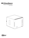
1
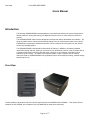
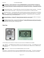
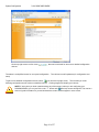
Front View
2 & 4 DRIVE USER GUIDE
Users Manual
Page 1 of 57
Front View
2 & 4 DRIVE USER GUIDE
Technical Support
Visionman Computers, Inc.
3200 N. San Marcos Place
Chandler, AZ 85225
Telephone: 1-800-690-6771 extension 2665
Support e-mail: [email protected]
For additional information, please visit the Visionman Web site: www.visionman.com
Copyright © 2008 Visionman.com.
All Rights Reserved.
Visionman makes no warranty or representations, expressed, implied, or statutory, with respect to its products or the contents or use of this documentation and all accompanying
software, and specifically disclaims its quality, performance, merchantability or fitness for any particular purpose. Visionman reserves the right to revise or update its products,
software, or documentation without obligation to notify any individual or entity.
GB means 1 billion bytes; actual formatted capacity varies with preloaded material and operating environment and will be less.
TB means 1 trillion bytes; actual formatted capacity varies with preloaded material and operating environment and will be less.
All product names and logos are the property of their respective owners.
ii
Page 2 of 57
Front View
2 & 4 DRIVE USER GUIDE
Introduction _____________________________________________________________________________ 4
Front View ____________________________________________________________________________________4
Rear View _____________________________________________________________________________________5
System Setup _____________________________________________________________________________ 6
Connecting the Storango SCM200/SCM400 to the Network ____________________________________________6
Connecting the Ethernet cable and power: ___________________________________________________________________6
Connecting a USB drive: _________________________________________________________________________________6
Connecting a USB printer:________________________________________________________________________________6
Turning the System On __________________________________________________________________________________6
Turning the System Off __________________________________________________________________________________7
Resetting the System ____________________________________________________________________________________7
System Configuration______________________________________________________________________ 7
Logging into the SCM200/SCM400 configuration utility_______________________________________________7
Windows, Linux, and Mac________________________________________________________________________________7
System Configuration ___________________________________________________________________________9
General Setup Screen___________________________________________________________________________________11
Alerts Setup __________________________________________________________________________________________12
Change Admin Password ________________________________________________________________________________13
Firmware Update ______________________________________________________________________________________14
Printer Management____________________________________________________________________________________15
Configuration Management ______________________________________________________________________________16
Advanced Setup _______________________________________________________________________________________18
Network: LAN Setup Screen _____________________________________________________________________________20
Network: Services _____________________________________________________________________________________22
Workgroup/Domain Setup _______________________________________________________________________________24
Storage Screens________________________________________________________________________________26
Disk Management Screen _______________________________________________________________________________26
Volume Management ___________________________________________________________________________________27
Manage RAID ________________________________________________________________________________________29
Share Management ____________________________________________________________________________________32
USB Management _____________________________________________________________________________________35
USB Backup _________________________________________________________________________________________36
Access Control Section__________________________________________________________________________37
User Management _____________________________________________________________________________________37
Group Management ____________________________________________________________________________________40
Share Access _________________________________________________________________________________________44
USB Access __________________________________________________________________________________________46
Using the Media Server _________________________________________________________________________________47
Using the Status Menu __________________________________________________________________________51
Logs ________________________________________________________________________________________________52
Product Support_______________________________________________________________________________55
Troubleshooting _______________________________________________________________________________________55
First Steps Checklist ___________________________________________________________________________________55
Specific Problems and Corrective Actions___________________________________________________________________55
Technical Specifications_________________________________________________________________________56
iii
Page 3 of 57
Front View
2 & 4 DRIVE USER GUIDE
Users Manual
Introduction
The Storango SCM200/SCM400 storage appliance is a powerful and feature-rich system designed as a
flexible solution for storing and sharing your digital files across a home or office network or across the
Internet.
The SCM200/SCM400 makes remote management a simple task with its Web-based user interface. By
using any Web-browser, network and operational settings, such as monitoring the status of the network,
installed disks, storage space utilization and others; can be configured from any system on the network,
running any operating system.
The SCM200/SCM400’s Web-based & Internet style file sharing, in addition to its industry standard
network file sharing methods, allows you to store all of your documents, pictures, music, and video files in
a central storage location and share files with other computers on your network, regardless of what
software they are running. No matter what computer system or style of network you are running,
chances are that he SCM200/SCM400 can significantly improve and simplify file sharing, network storage,
and backups for you.
Front View
The functionality of the buttons and LED’s are the same between the SCM200 and the SCM400.
examples for the SCM200, and exceptions for the SCM400 will be noted where necessary.
Page 4 of 57
This manual will use
Rear View
2 & 4 DRIVE USER GUIDE
Power Button: Press the power button to turn the SCM200/SCM400 on. The Green LED under the button will
indicate that the system is powered on. Press and hold the button to power the system down. If the LED is off,
then it indicates that either the system is still initializing or the system is not powered on. A blinking LED indicates
either the system is rebooting or the RAID is rebuilding, and will be unavailable for file sharing or administration during this
time.
Network Activity Indicator: The green LED under or next to this icon indicates a network connection. The blinking
of this LED indicates network traffic. When this LED is off, this indicates there is no network connection.
HDD Status Indicator: The blinking green LED’s indicates formatting, accessing or synchronization of the individual
drives. The solid green light indicates that the system is completely synchronized and is ready to use. And amber
LED indicates a drive error or an old HDD has been installed with data on it. When this LED is OFF, it means that the
drive is not installed correctly or has completely failed.
System Identification: This blue LED indicates that system identification is active. When this LED is off it indicates
that system identification is disabled. A blinking LED means there us a critical condition.
USB Backup Status Indicator: This green LED lights to indicate that a USB hard drive is attached, and the system
is rebuilding, restoring, or transmitting files to the USB drive. A blinking LED indicates that the system is backing up
the USB hard disk or that the system is formatting the drive.
Rear View
The functionality of the connections on the back is the same between the SCM400 and the SCM200.
USB Port: The SCM400 has three USB ports, two in the back and one in the front. The SCM200 has two USB
ports in the back. These ports allow for the connection of USB devices like a USB hard drive, a USB flash drive,
or a USB printer.
Ethernet Port:
This port connects the SCM200/SCM400 to the local network.
Reset Switch: Press the Reset button to restore the SCM200/SCM400 to factory settings. The button is recessed and
located above the Ethernet port on the SCM400 and between the power connector and Ethernet port on the SCM200.
Page 5 of 57
Connecting the Storango SCM200/SCM400 to the Network
2 & 4 DRIVE USER GUIDE
Power Connector: Use this port to connect power to the SCM200/SCM400. The SCM400 uses a standard computer
type AC power cord, whereas the SCM200 uses an AC to DC power adapter.
System Setup
This section gives instructions on how to setup the Storango SCM200/SCM400.
Connecting the Storango SCM200/SCM400 to the Network
Connecting the Ethernet cable and power:
Connect the Ethernet cable to the Ethernet port on the rear of Storango SCM200/SCM400.
Connect the other end of the Ethernet cable to a switch or router.
Connect the power to the power connector on the rear of SCM200/SCM400.
Connect the other end of the power cable or adapter to the nearest power receptacle.
Connecting a USB drive:
Connect the USB cable of your USB hard drive or the USB flash drive to the USB port next to the Ethernet port on
the SCM200/SCM400.
Connect the other end of the USB cable to the USB drive, if necessary.
Connect the USB drive to power, if necessary.
Connecting a USB printer:
Connect the USB cable to the top USB port on the rear of the SCM200/SCM400.
Connect the other end of the USB cable to your USB printer.
Install the printer driver if it is not installed on the computer you are printing from.
Turning the System On
Power the system on after confirming that all the cables have been connected properly.
LED’s will flash and turn different colors.
After 30 seconds, verify LED’s are on and correct. The power button and hard drive LEDs should be green. Network
LED should be green and may flash.
The SCM200/SCM400 and the computers must be on the same subnet, and DHCP/DNS must be enabled from
either a router or a server. If you are uncertain what these terms mean, contact your network administrator or the
manufacturer of your router.
Page 6 of 57
Logging into the SCM200/SCM400 configuration utility
2 & 4 DRIVE USER GUIDE
Turning the System Off
To power down the system, press and hold the power button down for about five seconds.
The green power LED will turn off, indicating that a shutdown is in progress.
The shutdown process will start and take about 10 to 15 seconds to complete.
When the other LED’s have turned off, the system is off.
Resetting the System
The storage solution has a reset button in the back. Pressing and holding the button down will reset the IP
Address, system name and the password for Administrator to factory settings. After holding the button down for
about 15 seconds, the hard drive LED’s will turn amber. This is an indication that the system has been reset,
and you can now release the button.
Factory default settings are as follows:
IP Address – This will reset the IP address to “DHCP Client”.
DHCP server or the router on the network.
The IP address will now be received from the
System Name – The system name will now be SCM400 or SCM200, depending upon your system.
Password – The password for the administrator will now be “admin”.
System Configuration
The storage solution has a web interface for configuration and set up.
configuration interface and what the various settings mean.
This section will explain how to access this
Logging into the SCM200/SCM400 configuration utility
Windows, Linux, and Mac
The web access to the configuration utility for Windows, Linux and Mac is the same.
Launch the Internet browser on your PC or Mac.
Type the following: http://SCM200/ or http://SCM400/, if you change the name of the device in the future, type
http://newname/ to access the device. You can also just type the IP address that is assigned by the DHCP server
to the storage device.
Page 7 of 57
Logging into the SCM200/SCM400 configuration utility
2 & 4 DRIVE USER GUIDE
The above screen will appear on your browser. If the page does not appear, please wait a few minutes and try
again. The default user name and password are: admin and admin
Please note that both the user name and the password are case sensitive.
In some cases it may be necessary to open the configuration file directly. You can do this by clicking on Start,
Run, and then typing in //SCM200 or //SCM400 depending on which unit you have. You will be prompted for a
username and password. It will be the same as previously mentioned (admin/admin).
Once you have clicked on OK or hit ENTER, you will see the following screen:
Page 8 of 57
System Configuration
2 & 4 DRIVE USER GUIDE
Open the configuration folder by double-clicking on that folder’s icon. Once inside this folder, open the Index file by
double-clicking its icon. This will bring you to the configuration login screen in the same way as typing the IP address or
name directly into your browser.
System Configuration
The web screen will now show the display below.
configuration.
This will provide you with a high level status of the storage system
On the left side is a list of configuration choices that you can select to change configurations.
explanatory in what configuration choices will become available.
Page 9 of 57
The titles are self
System Configuration
2 & 4 DRIVE USER GUIDE
On the top right corner are four Icons
choices:
, that can be selected for some more detailed configuration
The above is a simplified screen for set up and configuration.
setup.
The choices are self explanatory for configuration and
icon from the top right corner. This will take you to the
To get to more detailed configuration screens, select
following configuration screen, with more detailed choices. Clicking it again will simplify your choices.
NOTE: If at any time you have questions about any of the screens, when you are configuring your
SCM200/SCM400, you can just click on the “?” button and on online help screen will appear. This can be a
source of good information for you and eliminate the need to contact support in some cases.
Page 10 of 57
System Configuration
2 & 4 DRIVE USER GUIDE
General Setup Screen
This screen allows you to configure the basic information about the SCM200/SCM400 storage appliance, such as give a
name and brief description for the machine, select the web GUI protocol, and set the time zone for your storage device.
You can also set the date and time or enable automatic time synchronization via NTP (Network Time Protocol) Service.
You have to specify the IP address of the NTP servers from which you want to synchronize.
If you want to change the name of the Storage System, you can assign a new machine name for the
SCM200/SCM400. The name can contain up to 15 characters, including alphabetic, numeric, underscore, space,
and most special characters. We suggest that you keep it short and simple, so it is easier to remember. Please
note that if you have more then one storage solution, then they all need to have a unique names.
In the description box, enter the brief description for the storage appliance.
description must not be more than 256 alphanumeric characters.
The maximum length of the
The difference between the two HTTP and HTTPS protocols is that HTTPS is secure web access.
select the protocol that makes the most sense on your particular network.
You can
In the Time Zone drop-down menu, select the time zone for your location.
In the Date & Time drop-down menu, adjust the date and time manually.
You can set the date and time of the storage solution to automatically synchronize with an Internet public NTP
(Network Time Protocol) server. To set the date and time automatically, select the Enable checkbox in NTP
Service, then enter the IP address of the network time servers from which you want to synchronize.
Click Submit.
Page 11 of 57
System Configuration
2 & 4 DRIVE USER GUIDE
Alerts Setup
In the Alerts setup screen, you can configure the system to automatically send e-mails or pop-up messages for event
notification, to the administrator to monitor the functionality of the storage device. These messages can be warnings or
errors related to Fan, temperature, Hard Drive functionality, Volume, Network, USB, Users and Groups.
Configuring the email:
Select the Enable checkbox
Enter the SMTP server name or an IP address to be used for sending email.
In the SMTP Port box, enter the port number to be used when connected for SMTP sending of e-mail.
default port number for standard SMTP is 25, and 465 for secure SMTP.
The
In the Email Recipients box, enter the email address of the persons you wish to send an event email
message to. Up to five emails can be on this list.
Select Send Test Mail to send a test alert and confirm your settings are correct.
Select Submit.
Configure the pop-up message alert settings:
Select the Enable checkbox.
Enter the name of the computer you wish to send a pop-up message to, when an event occurs. Up to five
computer names can be added to this list. (This requires that messenger service is enabled on the
computers that you wish to send pop up messages.)
Select Send Test Pop-up to send a test alert and confirm your settings are correct.
Click Submit.
Page 12 of 57
System Configuration
2 & 4 DRIVE USER GUIDE
Change Admin Password
Change the administrator password:
Enter the old password.
Enter the new password. The maximum length of the password must not be more than 15 alphanumeric
characters. Password is case sensitive and should be entered exactly in the same way each time.
Re-enter the new password.
Click Submit.
Page 13 of 57
System Configuration
2 & 4 DRIVE USER GUIDE
Firmware Update
This screen provides information about the current firmware version and allows you to perform a firmware upgrade.
Check on our web site to see if a newer version of the firmware is available.
To upgrade the firmware:
Download a copy of the new firmware from our Website to your computer.
The firmware image filename should have the following format: <firmware version>.IMG; for example
SCM200_V0_1_6.IMG. When you download the firmware image file from the site, please be sure that the
filename is correct, and do not rename the file.
Select Browse to locate the file that you downloaded and select the correct IMG file (e.g.
SCM200_V0_1_6.img).
Select Submit to transfer the firmware file from your computer to the SCM200/SCM400 storage appliance.
Do not interrupt the firmware upgrade process. This may cause the system to become disabled, and
unable to function.
The update process might take a few minutes to complete.
After your firmware has been updated, the system will reboot to initialize the new firmware. The Web GUI will redirect you
to the System Information page after the update is completed.
Page 14 of 57
System Configuration
2 & 4 DRIVE USER GUIDE
Printer Management
The Printer Management screen allows you to manage the USB printers connected to the storage device, as well as
manage print queues and print jobs across the network.
Install the printer drivers on the PC’s that will use this printer.
For Windows:
Connect the USB printer to the storage device.
Open My Network Places > Entire Network > Microsoft Windows Network > Workgroup Name > Machine
Name (where Machine Name is the name of the SCM200/SCM400 storage appliance), then right-click on the
printer icon and select Connect.
Select your printer model from the list and click OK.
Managing print jobs:
To pause or resume printing of a document, click the Pause/Continue icon.
To cancel printing of a document, click the Cancel icon.
Page 15 of 57
System Configuration
2 & 4 DRIVE USER GUIDE
Configuration Management
Configuration Management screen allows administrators to easily perform backup or restore operation of the storage
systems settings or revert system to factory default settings.
To backup your current configuration settings:
On the Configuration Management page, click Configuration Download.
Click Open and specify a file name and location where you want to save the file and select save.
To restore your configuration settings:
On the Configuration Management page, click Browse.
Select the previously saved system configuration file, and select General Restore or Full Restore.
Selecting General Restore restores all features except the settings for data volume and shares to its
previously saved settings. While Full Restore erases all data on the SCM200/SCM400 and revert the data
volume and shares to its previously saved settings.
To restore SCM200/SCM400 to factory defaults:
Page 16 of 57
System Configuration
2 & 4 DRIVE USER GUIDE
Performing a factory default reset will erase all settings in SCM200/SCM400. System settings such as the IP
address, machine name, admin user name, password, RAID reconstructs, and media files stored in
SCM200/SCM400 are lost.
On the Configuration Management page, click Factory Default Restore and click OK.
It is important to backup all critical data and files before undertaking any restore operations.
Page 17 of 57
System Configuration
2 & 4 DRIVE USER GUIDE
Advanced Setup
This screen allows you to configure the system identification LED, setup a system for a secure connection by generating
an SSL (Secure Sockets Layer) certificate and a key, and perform a reboot or shutdown for the SCM200/SCM400.
To turn on the system identification LED:
Click the Turn LED ON button to enable the system identification LED, and select Submit.
This will turn the System Identification LED on, and this could be useful in identifying a particular storage
system if you have multiple units.
To generate an SSL certificate and an RSA key:
SSL is a protocol for managing the security of passing data back and forth between a client computer and
SCM200/SCM400 over the network. SSL uses two keys — a public and a private key, to encrypt data and to
ensure a scalable, efficient, and secure file-sharing over the Internet.
Administrators can generate an SSL certificate and an RSA key using this screen.
You can generate an SSL certificate and RSA key by using the System Configuration Utility.
On this screen, select the highlighted word “HERE”.
Enter the necessary information for generating an SSL certificate, then click Submit.
To use the “extend disk mode” feature:
Page 18 of 57
System Configuration
2 & 4 DRIVE USER GUIDE
By default, your storage system will place the installed disks in what is called a “span” configuration. This
utilizes all available disk space for networked storage. If your storage system does not have all the disk slots
used you may want to add more capacity later. If that is the case, you may want to enable the storage
system’s “Extend” mode.
Click on the drop down menu and select “Enabled” and then click on Submit.
Page 19 of 57
System Configuration
2 & 4 DRIVE USER GUIDE
Network: LAN Setup Screen
This screen allows access to all network configuration options; such as setting the connection method, changing the IP
address, netmask, gateway, DNS (Domain Name Service) server IP address, and the ability to configure the optional
jumbo frame size.
DHCP is the default network IP setting for the storage device. When this option is selected, the system automatically
acquires its IP address and IP settings from the DHCP server on the network.
A jumbo frame size support is also included for switch or routers that support jumbo frames. The storage device supports
jumbo Ethernet frames to enhance networking performance.
By default, the jumbo frame option is disabled.
To manually configure the IP settings:
You may want to manually configure the IP settings on your storage system if you are using a static IP
address.
On the Network Mode drop-down menu, select Static.
In the IP address box, enter a valid IP address and network prefix.
In the Default Gateway box, enter the IP address of the gateway or router.
In the DNS Servers box, enter the DNS server IP address.
Page 20 of 57
System Configuration
2 & 4 DRIVE USER GUIDE
In the MTU Size (Bytes) box, enter the appropriate MTU size.
Click Submit.
You must restart the system for these changes to take effect.
Page 21 of 57
System Configuration
2 & 4 DRIVE USER GUIDE
Network: Services
The Network services screen allows you to set up and manage file services for different types of clients, such as Mac,
Windows, Linux, Unix, on your network using the FTP (File Transfer Protocol) or NFS (Network File System) protocols.
Computers can access files and shared folders on your storage system, without requiring any special software.
FTP (File Transfer Protocol) services allow you to share files securely, between Storage System and other computers,
over the Internet.
To enable the FTP file service on the storage system:
On the Services page, click the FTP service Enable checkbox.
Click the Yes or No button to enable or disable anonymous access to the FTP server.
Public file sharing is easily accessed by enabling anonymous and selecting Submit.
To access SCM200/SCM400 through an FTP:
After you enable FTP files services, you can connect to the storage system via any FTP client.
For example if your SCM200/SCM400’s IP address is set to 11.45.57.82, entering ftp://11.45.57.82 in a browser or
Windows Explorer address bar will access the SCM200/SCM400’s public contents.
NFS services allow you to share files with other Linux or UNIX clients or clients who have the NFS client software.
Page 22 of 57
System Configuration
2 & 4 DRIVE USER GUIDE
To enable the NFS file service on SCM200/SCM400:
On the Services page, click the NFS service Enable checkbox.
The IP Allowed box appears. Enter the IP filters that are allowed for NFS service, then click Add to add the
new IP filter, and select Submit.
Page 23 of 57
System Configuration
2 & 4 DRIVE USER GUIDE
Workgroup/Domain Setup
This screen allows you to setup the storage system as a workgroup or domain member. Both workgroup and domain are
ways of grouping computers on the network. By default, the storage system is set as a Workgroup. Unlike workgroups,
domains are controlled from a central location (domain controller) and require central authentication before you can join
them.
Workgroups, in contrast, are much simpler to control. As long as you know the workgroup name, you can add any
computer to a workgroup.
To setup a workgroup name:
On the Workgroup/Domain Setup page, select the Workgroup button.
In the Workgroup Name box, enter a name for your workgroup, and select Submit.
The storage system will become a member of that workgroup.
Domain Setup
If your network uses a domain (i.e., has Windows Active Directory Services), you may wish to connect the
SCM200/SCM400 as a domain member.
When configured as a domain member, the storage system requests are coordinated by the domain controller on your
network to authenticate users. Domain mode has more restrictive security levels, as network users must enter
appropriate passwords before gaining access to SCM200/SCM400.
When joining a domain, SCM200/SCM400 needs the authorization of the domain’s administrator. You must enter the
Page 24 of 57
System Configuration
2 & 4 DRIVE USER GUIDE
Domain Name, Administrator and Administrator Password for the authorization.
To join a domain as a member:
Select the Domain Member button.
In the Domain Name box, enter the domain name.
In the Domain Controller IP Address box, enter the domain controller’s IP address.
In the Administrator box, enter the administrator’s user name.
In the Administrator Password box, enter the administrator’s password.
Click Submit.
Page 25 of 57
2 & 4 DRIVE USER GUIDE
Storage Screens
The Storage screens provide all the necessary options required for individual storage disk configuration and
maintenance. You can also change RAID configuration, set shared folder names, format and disconnect USB
hard drives that are connected to the system.
The above screen shows a screen shot from the SCM200, which has two drives. The SCM400 screens will
actually show up to four drives, and different RAID configurations. Beyond these two things, the screens will be
very similar.
Disk Management Screen
The Disk Management screen provides a detailed summary of the hard drives, installed on SCM200/SCM400.
Again, on a SCM400, you will see up to four drives listed, unlike the two drives on the SCM200.
The drive status allows you to monitor hard drive fault conditions and activity.
Good - Indicates the hard drive is accessible and functioning normally.
Failed - Indicates a fatal error has occurred, such as the hard drive partition has been deleted, corrupted, or
damaged, which could result in data loss.
Foreign - Indicates SCM200/SCM400 has detected an old hard drive or a hard drive containing other data has
been installed. A Clean disk icon
appears on disks that display the “Foreign” status. Unless the user
performs a clean disk operation, the hard drive cannot be accessed. After performing a clean disk operation, the
hard drive appears on the Disk Management table.
Page 26 of 57
Storage Screens
2 & 4 DRIVE USER GUIDE
Volume Management
The Manage Volume tab contains a table that shows all volumes currently defined on the SCM200/SCM400’s
hard drives and provides access to configuration details relating to how the disks are partitioned and how RAID
volumes are created on these partitions.
These volumes are the ones used for creating shares.
Manage Volume
The Manage Volume tab in the Volume Management submenu lists all the volumes available, and provides
detailed summary about each volume, such as the name of the volume, description, RAID type (Stripe, Mirror, or
Span), volume space used, total drive capacity, and status of the volume.
A volume is a portion of one or more hard disks that are configured to store data. On the Manage volume table,
the volume status that appears in the Status column includes the following values:
Good - Indicates the volume is accessible and hard drive is functioning normally.
Failed - Indicates a volume cannot be started automatically, the disk is damaged or the file system is
corrupt.
Re-synching - Occurs when creating a mirror or when a mirrored volume is being resynchronized so both
mirrors contain identical data. With the four drive system and a RAID 5 volume, this could indicate the
creation or recovery of the RAID set.
Formatting - Indicates volume is being formatted or system is creating an ext3 (third extended) file system
for a Linux operating system.
Page 27 of 57
Storage Screens
2 & 4 DRIVE USER GUIDE
Degraded - A drive is missing or contains corrupted data for the existing volume.
Recovering - Occurs when the system detects a spare drive that was inserted into a degraded RAID
volume.
Page 28 of 57
Storage Screens
2 & 4 DRIVE USER GUIDE
WARNING: CHANGING THE RAID TYPE WILL ERASE ALL DATA.
BEFORE CHANGING THE RAID SETTINGS.
PLEASE BACKUP YOUR FILES
Manage RAID
The Manage RAID screen allows you to configure the SATA hard drives into different RAID types.
RAID (Redundant Array of Independent Disk Drives) refers to an array of multiple independent hard drives that
provide high performance and reliability. RAID function depends on the number of drives present and the RAID
level you selected.
SCM200 supports the following RAID levels:
Stripe (RAID 0) - All data are distributed evenly to all existing drives. The two drives work in unison to
maximize system performance. However, RAID 0 has high risks of data security. If one drive fails then
all the data in both drives is lost.
Mirror (RAID 1) - Two hard drives are required. Data written to one hard drive is simultaneously duplicated
to another hard drive. If one drive fails, the other drive continues to function as a single drive until the
failed drive is replaced. To create a mirror you must select unallocated space on another hard drive and
the unallocated space must be the same size or larger than the source drive you want to mirror that data.
Data on a mirrored drive is secured, if one hard drive fails, SCM200 administers a warning and the failed
drive must be replaced immediately.
Span - Also known as a Linear array. Two hard drives are required. Several hard drives are configured
as a single volume with a size equal to the total of all the member disks. However, span does not
increase system performance or data security.
Page 29 of 57
Storage Screens
2 & 4 DRIVE USER GUIDE
Default RAID configuration - The default RAID configuration for each hard drive installed on SCM200 is
as follows:
• If one drive is installed to an empty drive bay, the default RAID configuration is mirror and
the volume status is degraded.
• If system has one hard drive and a new hard drive is added, the default RAID configuration
is mirror and the volume status is good.
• If two hard drives are installed to an empty drive bay, the default RAID configuration is span.
SCM400 supports the following RAID levels:
Stripe (RAID 0) - All data are distributed evenly to all existing drives. The two drives work in unison to
maximize system performance. However, RAID 0 has high risks of data security. If one drive fails then
all the data in both drives is lost.
Mirror (RAID 1) - Two hard drives are required. Data written to one hard drive is simultaneously duplicated
to another hard drive. If one drive fails, the other drive continues to function as a single drive until the
failed drive is replaced. If you have four drives, the system will offer the mirror option as “Two Mirror”.
In this configuration, up to two drives can fail before any data is lost.
Span - Also known as a Linear array. Two hard drives are required. Several hard drives are configured
as a single volume with a size equal to the total of all the member disks. However, span does not
increase system performance or data security.
RAID 5 – A minimum of three hard disks is required for this array type. This is a striped array with
distributed parity, forming a redundant array. This type of array gives good performance and protects the
data against any single drive failure.
Page 30 of 57
Storage Screens
2 & 4 DRIVE USER GUIDE
Default RAID configuration:
follows:
•
•
•
The default RAID configuration for each hard drive installed on SCM400 is as
If one drive is installed to an empty drive bay, the default RAID configuration is mirror and the
volume status is degrade.
If system has one hard drive and a new hard drive is added, the default RAID configuration is mirror
and the volume status is good.
If two or more hard drives are installed, the default RAID configuration is span.
Page 31 of 57
Storage Screens
2 & 4 DRIVE USER GUIDE
Share Management
This screen provides access to configuration details relating to how shares are made available by the SCM200/SCM400.
This menu contains a table that shows all the shares, logical volumes, and protocols currently defined on the
SCM200/SCM400 system.
SCM200/SCM400 comes preconfigured with four shared folders: download, media_library, public, and private.
Page 32 of 57
Storage Screens
2 & 4 DRIVE USER GUIDE
To create a new share on a logical volume:
Click on the Create icon
Assign a share name. The share name can contain up to 32 characters, including alphabetic, numeric, or
underscore.
Enter a brief description, if desired.
Select file sharing protocol.
The SCM200/SCM400 supports the following file sharing protocols:
CIFS (Common Internet File System) - A standard way that clients share files across intranets.
CIFS allows Windows, Mac, or Linux clients to access folders and files stored on your
SCM200/SCM400. The access control for CIFS is set to each shared folder. You can define
access rights for each user/group where the user will need to enter his/her password for
accessing that share. When the client browses the shares via Windows Explorer, he can only
see the shares which he has been granted access rights (Read Only or Full Access) to.
FTP (File Transfer Protocol) - Allows access to files on SCM200/SCM400 from most computers
whether they are inside or outside your local network.
HTTP (Hypertext Transfer Protocol) - Allows access to folders and files on your SCM200/SCM400
using a Web browser. This method of access is unique, as most NAS boxes will not allow you to
access the files in this way. You can, quite literally, access the files on the SCM200/SCM400
from any system with a web browser regardless, including some PDA’s and cell phones.
NFS (Network File System) - Allows Linux clients or clients who have TCP/IP installed to remotely
access folders and files on your SCM200/SCM400.
Page 33 of 57
Storage Screens
2 & 4 DRIVE USER GUIDE
Using NFS protocol, the client can access all or a portion of the shared file directory on the
network. The portion of the file directory can be accessed with the privileges (read only or full
access) designated to each file.
Click Submit.
NOTE: If you have “Setup access control after creating share” checked, you will be taken directly
to the Access Control for this share and you can assign users or make the share public for your
network. Please refer to that section for more information.
To modify the share properties:
Click on the Modify icon.
Assign a new share name. The share name can contain up to 32 characters, including alphabetic,
numeric, or underscore.
Enter a brief description, if desired.
Select a file sharing protocol.
Click Submit to save your changes.
To delete existing shares:
Select the share you want to delete.
Click the Delete icon.
A warning dialog box will appear.
Click on OK to delete the share.
Page 34 of 57
Storage Screens
2 & 4 DRIVE USER GUIDE
USB Management
The Storage Appliance supports USB external hard disk drives and USB Flash drives.
CD/DVD/CDRW/DVDRW Drives.
To format a USB hard drive:
partitions, volumes…etc.)
It does not support USB
(Remember, formatting a drive erases all data from the drive, including any
Connect a USB hard drive to SCM200/SCM400.
On the USB Management page, select the USB Disk tab.
Select the USB hard drive you want to format and click the Format icon.
A dialog box appears warning that all data will be erased.
Click OK.
To disconnect a USB hard drive from SCM200/SCM400:
On the USB Disk tab, select the device you wish to remove.
Click the Safely Remove Disk icon.
Click OK.
Page 35 of 57
Storage Screens
2 & 4 DRIVE USER GUIDE
USB Backup
USB port number one, which is next to the Ethernet port on the SCM200 and on the front for the SCM400, has been
configured to handle the automatic backup of the contents of a USB drive attached to the SCM200/SCM400. You can
use the other USB port(s) for transferring data to and from the storage system, but only USB port one can be used for
automatic backup.
To set a destination share name for the USB hard drive:
On the USB Management page, select the USB Backup tab.
Select a share to be used as a default backup share from the Destination Share drop-down menu. This
is where all the files will be copied to from the USB drive. A folder within this share will be automatically
created based on the volume name of the USB hard disk.
Click Submit.
Page 36 of 57
Access Control Section
2 & 4 DRIVE USER GUIDE
Access Control Section
The Access Control screens allow you to configure access to files and folder in the Storage Appliance.
User Management
The User Management screen allows the system administrator to create, edit, and delete user accounts on the system.
Administrators can create Public or Private user accounts and further customize these accounts with privilege levels.
To create a user account:
Click the Create icon.
And the following screen will come up:
Page 37 of 57
Access Control Section
2 & 4 DRIVE USER GUIDE
In the User name box, enter the user name.
Click the Grant Administration Rights checkbox to allow user to have administrative rights and to
access and configure the System Configuration Utility.
In the Full Name box, enter the user’s full name.
To secure the shared folder so that users must use a password to access it, enter a password in the
Password box. The user name and passwords are case sensitive, and can contain up to 15 characters,
including alphabet, numbers, underscore, and some special characters.
In the Confirm Password box, re-enter the password for confirmation.
In the Group List select a previously created Group for the user to join in.
Click the >> button.
Select the Yes button in the Create User Private Share if you want to create a private folder for this user.
Select an appropriate file sharing protocol to allow this share to be accessed by the user. The share will
have the same name as the user’s name.
Click Submit.
Page 38 of 57
Access Control Section
2 & 4 DRIVE USER GUIDE
The above screen shows the new user has been added successfully.
To modify a user account:
Select the user account you want to modify.
Click the Modify icon.
The following screen will come up:
Page 39 of 57
Access Control Section
2 & 4 DRIVE USER GUIDE
Make the changes you want, then click Submit.
To delete a user:
Select the user account you want to delete.
Click the Delete icon.
You will get a warning about deleting of the user.
Click on OK, and the user will be deleted.
Group Management
The Group Management submenu allows administrators to create, edit, and delete
a group of users on the system.
Page 40 of 57
Access Control Section
2 & 4 DRIVE USER GUIDE
To create a new local group:
Click the Create icon.
And the following screen will come up:
Page 41 of 57
Access Control Section
2 & 4 DRIVE USER GUIDE
Assign a new group name for the new group.
As before, the name can be up to 32 characters long.
Enter a description for the new group.
In the User List, add the users that you want to have access to the group.
And Click Submit.
The following screen will show up to confirm that you have successfully created a new group.
Page 42 of 57
Access Control Section
2 & 4 DRIVE USER GUIDE
To modify a local group:
Select the group you want to modify.
Click the Modify icon.
Page 43 of 57
Access Control Section
2 & 4 DRIVE USER GUIDE
Make the changes you want, and then click Submit.
To delete a local group:
Select the group you want to delete.
Click the Delete icon.
You will get a warning to confirm the deletion of the user group.
Share Access
The Share Access screen allows administrators to set the access control for each user or group in the Access list. Each
user or group defined in User Management must have an assigned privilege level for every shared folder on the storage
appliance.
There are three privilege levels assigned to a user or group.
Full Access
Read Only
No Access
When there is a conflict in the access rights of the user and group, SCM200/SCM400 uses the following rule to handle the
conflict:
Page 44 of 57
Access Control Section
2 & 4 DRIVE USER GUIDE
No Access has the highest priority.
Read Write + Read Only = Full Access.
If the access control is assigned to a user or group, the full access, read only, and no access icons appear on the Share
Access page. You can move your mouse over the icon to view the user or group list.
To assign privilege levels for users or groups:
Select a user or group, then click the Edit icon.
Page 45 of 57
Access Control Section
2 & 4 DRIVE USER GUIDE
The upper section of the page contains an information table that lists the share folder’s logical volume name and
supported file service protocol. Each defined user or group must have a privilege level for every shared folder you create.
Click the Enable Public Access checkbox if you want to enable any user or group to have access to the
shared folder.
In NFS Access, you can set a privilege level for a Linux or Unix client.
In the Not Assigned Users list, select the users you want to grant full access, read only permission, or no
access to the logical volume.
Click the >> button.
In the Not Assigned Groups list, select the local groups you want to grant full access, ready only permission,
or no access to the logical volume.
Click the >> button.
Click Submit.
USB Access
The USB Access submenu allows you to set the access control for the two USB ports on the rear of SCM200, and the one
additional USB port in the front of the SCM400. There are three privilege levels that you can assign to a user or group are
Full Access, Read Only, or No Access.
Page 46 of 57
Access Control Section
2 & 4 DRIVE USER GUIDE
When there is a conflict in the access rights of the user and group, SCM200/SCM400 uses the following rule to handle the
conflict:
No Access has the highest priority.
Read Write + Read Only = Full Access.
If the access control is set, a small icon appears on User/Group permission box, the administrator can move the mouse
cursor over the icon to see the user/group list.
To configure the privilege levels for a USB share:
Select a USB share, then click the Edit icon.
Make the changes you want, then click Submit.
Using the Media Server
This feature allows the Storage appliance to automatically sort media files into Music, Photo and Video categories and
make them available on the network.
Page 47 of 57
Access Control Section
2 & 4 DRIVE USER GUIDE
Enable the Media Server by selecting the Enable button.
You can also decide if you want the media files sorted in alphabetical order or by the date the file was created.
Select Submit, for the system to sort the media content in the system and save your changes.
Page 48 of 57
Access Control Section
2 & 4 DRIVE USER GUIDE
The above screen will show that media content in the storage system has been identified and sorted.
Page 49 of 57
Access Control Section
2 & 4 DRIVE USER GUIDE
Enable the iTunes Server by selecting the Enable button.
Select Submit, for the system to save your changes.
You will then see the server appear in the shared area on your iTunes application. Any songs you have
transferred to the media_library will automatically appear when you click on the server name. A server named
“S3M” has been configured in the following example.
Page 50 of 57
Using the Status Menu
2 & 4 DRIVE USER GUIDE
The above screen will show that media content in the storage system has been identified and sorted.
Using the Status Menu
The Status menu displays general information about the system, such as machine name, firmware version, current
date/time, machine up-time, and volume of the storage space that is being used.
Page 51 of 57
Using the Status Menu
2 & 4 DRIVE USER GUIDE
Logs
Logs screen includes five tabs — System, CIFS, FTP, Printer, Settings. It displays a record of activity that has occurred on
storage device. Each activity displays a time and date associated with the event and a description of the activity that took
place.
Settings Tab
In the settings tab, you can decide the sequence that the log should be showed and the size of the log.
System
In the System tab, you will view information about the system, file and services requested, Web pages transferred from
SCM200/SCM400 to a client computer, or print events.
Page 52 of 57
Using the Status Menu
2 & 4 DRIVE USER GUIDE
The above is an example of the display from the system logs screen.
The System Logs records significant problems that occur in the system. You can obtain information from the following
conditions or errors that may occur in the system components, hardware or software components.
System shutdown
System reboot
Fan failed or defective fan
System temperature exceeds a threshold value
Disk SMART failure
Volume failed or does not exist
Volume space is full or close to 100%
Unsafe removal of a USB mass storage device
Each event is classified into following types:
Critical - An event such as fan failed, system temperature has exceeded the threshold level, Disk SMART failed,
volume space is full or close to 100%. When a critical event occurs, the system status LED lights up and the
system records the events in the System Log.
Warning - An event that is not necessarily significant, but may indicate a possible future problem. An email or popup message alert is sent to notify user of the problem that occurred in the system.
Information - An event that describes the successful operation of an application, driver, or service.
Page 53 of 57
Using the Status Menu
2 & 4 DRIVE USER GUIDE
The CIFS, FTP and Printer tabs track the logs for their respective functions.
CIFS
The CIFS (Common Internet File System) tab displays the file and print services log
of CIFS clients.
FTP
The FTP (File Transfer Protocol) tab displays file transfer sessions to and from the SCM200/SCM400.
Printer
The Printer tab displays the print services log.
Page 54 of 57
Product Support
2 & 4 DRIVE USER GUIDE
Product Support
To get the latest firmware, please visit Visionman.com web site to find the latest firmware version, and instructions on
how to download and update the firmware on your Storango SCM200/SCM400.
Troubleshooting
For any issue, first ensure that you are using the latest firmware for the Storango SCM200/SCM400.
resolve your server problems on your own, contact your dealer or Storango for assistance.
If you are unable to
First Steps Checklist
Is power being supplied to the unit?
Are all cables correctly connected and secured?
Turn the power on by pressing the switch.
flashing).
The Power LED should light up and be steady on (not
Specific Problems and Corrective Actions
The following contains specific problems that may arise during the use of your server. Possible
solutions are listed for each problem.
HDD activity indicator does not light.
If the drives are pre-installed (came with the system), contact technical support for assistance.
If you installed the drives, make sure that the drives are seated securely and properly in their respective
slots. The front drive latch should click when it is correctly in the slot and be almost flush with the front of
the unit (with the door open).
System cannot connect to a network and network status indicator does not light.
Make sure the network cable is securely attached to the correct connector at the system rear panel.
Confirm that the network is functional, by checking other devices on the network to confirm that network
access is working properly.
Try a different network cable.
Cannot view System Configuration Utility in the Web browser.
Make sure JavaScript is enabled in your browser. The following describes how to enable JavaScript
using Internet Explorer 6.0 and Mozilla Firefox (1.0 and 1.5) for Windows.
To enable JavaScript in Internet Explorer 6.0:
Page 55 of 57
Technical Specifications
2 & 4 DRIVE USER GUIDE
From the Internet Explorer menu, go to Tools, then select Internet Options.
Choose the Security tab, then click Custom Level.
Scroll down to Active Scripting, then select Enable.
Click OK.
To enable JavaScript in Mozilla Firefox 1.0:
From the Mozilla Firefox browser, select Tools.
Click Options, then select Web Features.
Select the Enable JavaScript check box, then click OK.
To enable JavaScript in Mozilla Firefox 1.5:
From the Mozilla Firefox browser, select Tools.
Click Content.
Select the Enable JavaScript check box, then click OK.
How do I manually create a pair of SSL certificate and key on a Linux system?
Generate a RSA private key by typing the following commands:
/usr/bin/openssl genrsa 1024 > server.key/bin/cat server.key
From the Mozilla Firefox browser, select Tools.
Copy and paste to the Key field of the SSL Certificate/Key on the Advanced Setup page.
Create a self-signed certificate by typing the following commands:
/usr/bin/openssl req -new -key server.key -x509 -out server.crt/bin/cat server.crt
Copy and paste to the Certificate field of the SSL Certificate/Key on the Advanced Setup page.
Technical Specifications
The table below lists the technical specifications for the Storango SCM200/SCM400 storage appliance.
Model Name
Storango SCM200/SCM400
Form Factor
4-bay for the SCM400
2-bay for the SCM200
Processor
Marvell 5281 500 MHz AMR9 SOC for the SCM400
Marvell 5182 500 MHz ARM9 SOC for the SCM200
Memory
128 MB DDR333 SDRAM for application storage
Page 56 of 57
Technical Specifications
2 & 4 DRIVE USER GUIDE
16 MB flash ROM for firmware storage
Storage Capacity
320 GBs - 2 TBs
Hard Drives Supported
3.5” SATA II 7200 RPM Hard Drive Buffer Size
8 MB
cache and above
RAID Constructs
RAID 0 (Stripe), 1 (Mirror), 5 (Parity), Linear (Span)
USB interface
3 (SCM400) and 2 (SCM200) x USB 2.0 ports for USB device extension
and file backup
Ethernet
(10/100/1000) Gigabit Ethernet port
IP
DHCP (Auto IP, changes), Static (Manual, constant) Protocols
HTTPS, CIFS, NFS, FTP, SMB
Operating Systems
Windows Vista, Windows 2000 SP4, Windows XP, Windows 2003,
Red Hat Enterprise Linux 2.6.7, MAC OS 10.1
File Systems
NTFS, FAT
W x H x D (in)
9.5 x 11.5 x 11 in (SCM200)
6 x 7.5 x 11 in (SCM400)
Weight (lbs)
6 lbs (SCM200)
16 lbs (SCM400)
Power Requirement
100-240 V 50/60 Hz
Consumption
150 W max
Operating Temperature
0 to -40 deg C
Operating Humidity
0% to 80% (non-condensing) Operating Shock
3 ms
Non-Operating Shock
30 G, 1 ms
Operating Vibration
0.25 G at 2 Hz to 200 Hz
Safety and Agency
FCC Class A / CE / UL / CB
Page 57 of 57
3.5 G.
HTTP,