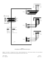
1
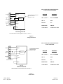
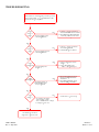
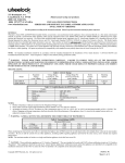
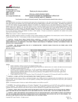
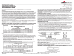
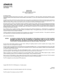
273 Branchport Avenue
Long Branch, NJ 07740
(800) 631-2148
www.wheeelockinc.com
Thank you for using our products.
INSTALLATION INSTRUCTIONS
AUXILIARY INPUT MODULE
Use this product according to this instruction manual. Please keep this instruction manual for future reference.
Model Numbers:
AIM-3
107387
Auxiliary Input Module
General:
The AIM-3 is an outboard expansion module for use with the SAFEPATH control panels to expand the number of optional Remote
Microphones (RM) from 1 to 3. The module is compatible with all SAFEPATH panels and Remote Microphones. The PCB
assembly is mounted in an enclosure.
READ THESE INSTRUCTIONS CAREFULLY BEFORE USING THIS PRODUCT.
NOTE: All CAUTIONS and WARNINGS are identified by the symbol
RM
PORT
. All warnings are printed in bold capital letters.
INPUT
PORT
SAFE PATH
RM
PORT 1
REMOTE
MICROPHONE
1
RM
PORT 2
REMOTE
MICROPHONE
2
RM
PORT 3
REMOTE
MICROPHONE
3
AIM-3
PANEL
OR
TELEPHONE
PAGING
Figure 1.
Basic Capabilities of the AIM-3
NOTE: Up to 3 Remote Microphones or up to 2 Remote Microphones and a telephone page port, may be connected to a SAFEPATH
Panel with an AIM-3.
NOTE: When using the AIM-3 for telephone paging on a SAFEPATH panel that is using Remote SAFEPATH panels for strobe
activation, the strobe circuits connected to the Remote SAFEPATH’s will activate during a telephone page.
Copyright 2003 Wheelock, Inc. All rights reserved.
AIM-3 Manual
Rev. C July 2003
P83667 C
Sheet 1 of 12
Technical Specifications:
Electrical
Input Voltage
24VDC
Input Current
100mA Telephone Page
60mA RM Page
40mA Standby
Audio Input
1Vrms
Mechanical
Dimensions (H x W x D)
13.0" x 7.6" x 2.15", 33cm x 19.4cm x 5.4cm
Weight
3.8 pounds, 1.7kg
Enclosure
0.050" Steel
Finish
Black
Mounting
Indoor Surface Mount
Top and Bottom Wiring Entry
Environmental
(Meets UL requirements)
Operating Temperature
0° to +49° C, 32° to 120.2 ° F
Storage Temperature
-20° to 70° C, -4° to 158° F
Humidity
85±5% @ 30±2° C Non-condensing
Installation:
AIM-3 Manual
Rev. C July 2003
P83667 C
Sheet 2 of 12
The lives of people depend upon your safe installation of the AIM-3. Please read, understand and follow the specific installation
instructions set forth below to avoid damage to the AIM-3 and equipment connected to it. Installation should be conducted only
by qualified persons in accordance with procedures in this manual.
WARNING: SHUT OFF ALL POWER BEFORE STARTING THE INSTALLATION. ELECTRICAL SHOCK CAN
CAUSE DEATH OR SERIOUS INJURY.
CAUTION: The AIM-3 printed circuit boards are sensitive to static electricity and have delicate components mounted on them.
Before handling either a board or any component on a board, discharge any static electricity from your body by touching a grounded
object such as a metal screw which is connected to earth ground. Handle the board by its edges, and be careful not to twist or flex it.
The AIM-3 is to be installed in a static free area and the user is to properly attach grounded wrist straps before touching any static
sensitive areas. After handling AIM-3 printed circuit boards, the Series AIM-3 should be tested in accordance with the “System
Checkout” section to verify that the printed circuit boards are undamaged and functioning properly.
CAUTION: The Authority Having Jurisdiction (AHJ) should be consulted by the installer prior to installation.
Installation Guidelines:
1. Prepare a drawing of the complete system wiring. (Keep a copy of the system wiring drawing and the AIM-3 Manual with the
SAFEPATH panel for reference during the life of the system.) This manual shall be made available to all qualified personnel
who operate, test, maintain, or service SAFEPATH products.
2. Carefully unpack the AIM-3 and make sure each item described on the packing slip is present and undamaged.
3. Mount the AIM-3 in the desired location as described in the "Mounting" section.
4. Mount any additional wiring boxes or junction boxes needed to interconnect field wiring.
5. Connect conduit fittings or bushings as needed using knockouts provided on the top and bottom of the AIM-3 units (see Figure
2).
6. Install field wiring in conduit when necessary, following the National Electrical Code and local codes for the type of system
being installed. Make all necessary connections at any additional wiring or junction boxes.
CAUTION: Provide proper strain relief for all wiring not in conduit.
7. Connect the AIM-3 to earth ground, following the National Electrical Code and local codes for the type of system being
installed, as described in the “Grounding” section.
8. Check the integrity of all field wiring following the directions in the "Field Wiring Checkout'' section. Confirm that the
specified cable is installed and that there is continuity between required points (no open circuits), with no unwanted connections
(shorts) to other conductors, chassis, or earth ground.
9. Connect the wiring to the appropriate terminals of the AIM-3 modules following the directions in the "Field Wiring" section and
the system wiring drawing you created in Step 1.
10. Set the switches for the proper configuration as described in the “Configuration” section.
11. For telephone applications set page volume as described in the “Operation” section.
NOTE: The AIM-3 has no user controls or interface. Once it is installed and configured the enclosure is closed up.
AIM-3 Manual
Rev. C July 2003
P83667 C
Sheet 3 of 12
Wiring Guidelines:
Although the AIM-3 incorporates signal verification and noise filtering circuitry on its input, induced voltages or “noise” on the input
wiring can cause improper operation. Therefore, use shielded twisted pair wire for all file input wiring. The audio output lines (and
the auxiliary music input lines) should also be wired with shielded twisted pairs to minimize noise pick-up. For all other connections,
twisted pairs are recommended so as to reject common mode noise, shielding is optional.
The shield of each cable should be connected only at one end. Each shield of each cable that connects to the AIM-3 is to connect to
the grounding points provided near the right edge of the chassis (see Figure 2).
WARNING: ALL AIM-3 WIRING SHOULD BE ROUTED AWAY FROM ANY HIGH VOLTAGE OR HIGH
CURRENT LINES (SUCH AS AC OR DC POWER LINE, AUDIO POWER LINES, AND MOTOR OR RELAY
ACTUATION LINES) AND SHOULD BE INSTALLED IN SEPARATE CONDUIT FROM HIGH VOLTAGE OR HIGH
CURRENT LINES. FAILURE TO DO SO MAY CAUSE ELECTRICAL SHOCK WHICH CAN RESULT IN PROPERTY
DAMAGE AND SERIOUS INJURY OR DEATH TO YOU AND/OR OTHERS.
The National Electrical Code defines two types of circuits for protective signaling systems: power limited circuits and non-power
limited circuits. All AIM-3 circuits have been designed as power limited circuits. Therefore, in order to maintain power limited
ratings, circuits connected to the power supply, auxiliary source input, and relay contact terminals of the AIM-3 must be powered
limited.
CAUTION: The National Electric Code limits the maximum number of conductors that can be installed in conduit and wiring
boxes depending on the size of the conduit, the volume of the boxes, and the gauge of the wire used. Make sure that wiring used for
AIM-3 installation complies with the latest NEC requirements for power limited circuits.
Wiring Specifications:
Between each RM and AIM-3
Cable Size:
14 - 22 AWG Shielded. The shield must be connected only at the SAFEPATH Panel.
Maximum Length:
1000 Feet
Maximum Capacitance:
. 05uF/Total Run (50pF/foot for 1000 FT.)
Mounting:
The AIM-3 shall be mounted in a location within the environmental limits specified in the latest UL Standard for indoor control
panels. The AIM-3 shall not be located in a hazardous location. Refer to the "Technical Specifications'' section.
CAUTION: In order to comply with the latest NFPA and UL requirements for interconnection of fire alarm control equipment,
the AIM-3 unit must be located in the same room as, and within 20 feet of the SAFEPATH Panel it is connected to.
Refer to Figure 2 for AIM-3 mounting hole layout. Drill mounting holes for appropriate screws and anchors to ensure secure
mounting to the type of surface at the selected location. Keep out dust and dirt during installation. Dust and dirt can interfere with
the operation and reduce the life of the equipment.
Remove the outer cover and mount the Series AIM-3 at the selected location. Use care to avoid damage to the PC board during
installation. Do not apply excessive pressure to the PC board or its components, including field wiring terminals and connectors or
damage may occur.
AIM-3 Manual
Rev. C July 2003
P83667 C
Sheet 4 of 12
CONDUIT KNOCKOUTS
2 PLACES, BOTH ENDS
6.00"
MOUNTING HOLES
GROUND
TERMINALS
11.00"
MOUNTING HOLES
Figure 2.
AIM-3 Mounting
NOTE: Drawing is not to scale.
AIM-3 Manual
Rev. C July 2003
P83667 C
Sheet 5 of 12
TB2
RMS #1
- +
RM AUDIO
RM POWER
- +
RM TXD
RM RXD
REMOTE MICROPHONES
1 2 3 4 5 6
+
RM AUDIO
RM TXD
RM RXD
+
RM POWER
-
SAFEPATH PANEL
TB1
RM POWER
+
POWER
-
- +
TB3
RMS #2
AIM-3 SWITCH CONFIGURATION:
SWITCH
POSITION
SEL. 1, 2, 3
ON AS NEEDED
PHONE
OFF
RM/PHONE
RM
TALK BATT
TALK BATT OFF
- +
RM AUDIO
RXD
RM TXD
RM RXD
RM RXD
REMOTE MICROPHONE
1 2 3 4 5 6
RM POWER
RM TXD
+
AUDIO
TXD
RM AUDIO
+
RM AUDIO
RM TXD
RM RXD
+
RM POWER
-
REMOTE MICROPHONES
RMS #3
- +
RM AUDIO
TB4
RM POWER
- +
RM TXD
RM RXD
1 2 3 4 5 6
+
RM AUDIO
RM TXD
RM RXD
+
RM POWER
-
AIM-3
Figure 3.
Wiring Diagram with up to 3 Remote Microphones
NOTE: If the AIM-3 is configured for less than 3 Remote Microphones, the +/- RM AUDIO terminals of the unused Remote
Microphone port must be terminated with the supplied listed 10K ohm 1/4W resistor.
AIM-3 Manual
Rev. C July 2003
P83667 C
Sheet 6 of 12
Telephone Input Applications:
The AIM-3 can be connected to an unused CO Port, a page port, an analog station port ( with TPI-100 ) or to a zone control (MCZ144 ). When it is used for telephone paging, it should only be used for telephone paging only and not for background music. The
VOLUME adjust is used to set the telephone page volume. When using the AIM-3 with the single circuit SAFEPATH (SC-SAPE ),
verify the SC-SAPE controller software (U5) is Rev E or higher. When using the AIM-3 with other SAFEPATH panels, verify the
controller software (U3) is Rev D or higher. Failure to do so could result in improper operation.
AIM-3 SWITCH CONFIGURATION:
UNUSED CO PORTS
TIP
+
AUDIO
SWITCH
UNUSED CO PORT
NC
TXD
RXD/CC
NC
NC = NO CONNECTION
+
POSITION
RING
-
NC
SEL. 1, SEL. 2
ON AS NEEDED
SEL. 3
OFF
PHONE
ON
RM/PHONE
PHONE
TALK BATT
TALK BATT ON
POWER
CC
-
NC
RMS-3 OF AIM-3
Figure 4.
Unused CO Ports
AIM-3 SWITCH CONFIGURATION:
PAGE PORT
+
AUDIO
-
+
AUDIO OUT
SWITCH
POSITION
-
TXD
SEL. 1, SEL. 2
ON AS NEEDED
SEL. 3
OFF
PHONE
ON
RM/PHONE
PHONE
TALK BATT
TALK BATT OFF
RXD/CC
+
POWER
CC
CONTACT
CLOSURE
RMS-3 OF AIM-3
PAGE PORT
Figure 5.
Page Port
AIM-3 Manual
Rev. C July 2003
P83667 C
Sheet 7 of 12
AIM-3 SWITCH CONFIGURATION:
ANALOG STATION PORT
+
+
AUDIO
ZONE 1
-
AUDIO MZEM-3 BOARD
ONE WAYZONE
CENTRAL AMP
-
TXD
+
NC
ZONE A
RXD/CC
-
SWITCH
POSITION
SEL. 1, SEL. 2
ON AS NEEDED
SEL. 3
OFF
PHONE
ON
RM/PHONE
PHONE
TALK BATT
TALK BATT OFF
GND
+
POWER
CC
-24VDC
-
RMS-3 OF AIM-3
+
AMP 1
MZC-144
TALKBACK DEFEATED
MAIN UNIT ZONE AMP
PROGRAMMED ZONE ENABLES ZONE 1 & ZONE A
Figure 6.
Analog Station Port
AIM-3 SWITCH CONFIGURATION:
ZONE CONTROL
ZONE 1
AUDIO
TXD
AUDIO MZEM-3 BOARD
ONE WAYZONE
CENTRAL AMP
SWITCH
POSITION
SEL. 1, SEL. 2
ON AS NEEDED
SEL. 3
OFF
PHONE
ON
RM/PHONE
PHONE
TALK BATT
TALK BATT OFF
ZONE A
RXD/CC
GND
POWER
CC
24VDC
RMS-3 OF AIM-3
AMP 1
MZC-144
TALKBACK DEFEATED
MAIN UNIT ZONE AMP
PROGRAMMED ZONE ENABLES ZONE 1 & ZONE A
Figure 7.
Zone Control
AIM-3 Manual
Rev. C July 2003
P83667 C
Sheet 8 of 12
Field Wiring Checkout:
Refer to NFPA for guidelines on testing signaling system wiring.
CAUTION: Do not connect input voltage to any equipment until the field wiring has been inspected, tested and approved.
1.
Verify that the field wiring is in full agreement with this manual and with the detailed wiring layout prepared for this installation.
Ensure that no unwanted voltages are present on circuit conductors and ground.
2.
Test all ungrounded connectors for electrical isolation from ground.
3.
Test all wires that are not intentionally connected for electrical isolation from each other.
4.
Measure and record the resistance of each circuit pair (this can be done by temporarily short circuiting one end of the circuit).
Configuration:
Configure the AIM-3 by using the three switches and potentiometer ( see Figure 8):
RM1 on enables the Remote Microphone attached to RMS-1 port.
RM2 on enables the Remote Microphone attached to RMS-2 port.
RM3 on enables the Remote Microphone attached to RMS-3 port.
PHONE on enables the telephone input attached to RMS-3 port.
RM/ PHONE RM enables Remote Microphone attached to RMS-3 port.
PHONE enables the telephone input attached to RMS-3 port.
TALK BATT provides talk battery for unused CO Port.
Volume potentiometer is used to adjust telephone page volume.
Operation:
The AIM-3 polls the Remote Microphone stations to determine supervision and alarm status. Any trouble condition will light the
amber LED. Follow the trouble shooting procedures if the LED is lit. The first Remote Microphone that is selected will have priority
over the other two. See the Remote Microphone instructions for Remote Microphone operation.
To set the telephone page volume use the VOLUME potentiometer adjust and the PEAK level red LED. Occasional flickering of the
LED indicates momentary peak levels, and is a normal operating condition. Steady illumination of the LED is an indication that an
overdrive (clipping) condition may exist. If distortion is audible, then lower the page volume.
AIM-3 Manual
Rev. C July 2003
P83667 C
Sheet 9 of 12
TRB
SEL3
SEL2
SEL1
O1 2 3 4
N
PHONE
F1
TO RMS #1 TO SAFEPATH
TB1
TO RMS #3
TXD
RXD
+
- POWER
+
- AUDIO
TXD
RXD
+
- POWER
+
- AUDIO
TXD
RXD/CC
+
- POWER
TB 4
F3
PHONE
+
- AUDIO
TALK
BATT
PEAK
VOLUME
RM
F2
TO RMS #2
TB2
TB3
+
- AUDIO
TXD
RXD
+
- POWER
Figure 8.
AIM-3 Board Layout
AIM-3 Manual
Rev. C July 2003
P83667 C
Sheet 10 of 12
TROUBLESHOOTING:
While AIM-3 is connected and powered up, switch
SW1 positions SEL. 1, 2, 3 and PHONE to OFF.
Switch ON as to be cofigured.
Verify
No
Power to
AIM-3
1. Check +/- power connection
from SAFEPATH Panel to AIM-3.
2. Check RMS fuse on SAFEPATH
controller printed circuit board.
Are any LED'S on any
connected RMS lit?
Yes
Verify
No
Power to
RMS
1. Check +/- power connection
from AIM-3 to RMS.
2. Check RMS fuse on AIM-3.
Are any LED'S on each
connected RMS lit?
Yes
Yes
Verify
Configuration
1. Verify configuration switch
is OFF.
2. Verify 10K OHM across
audio +/- for unused port.
Are any RMS ports
unused?
No
Verify
Serial
Communications
Yes
1. Check TXD and RXD wiring
between SAFEPATH Panel
and AIM-3.
2. Check TXD and RXD wiring
between AIM-3 and RMS.
Are amber LED's on
RMS flashing about
once per second?
No
No
Verify
Check audio +/- pair wiring.
Audio +/In stand-by non alarm
state, check +/- audio
and +/- RM audio DC voltage.
Is voltage -12V +/-1V?
Yes
Call Wheelock Technical
Support at 1-800-631-2148
AIM-3 Manual
Rev. C July 2003
P83667 C
Sheet 11 of 12
Limited Warranty
Wheelock products must be used within their published specifications and must be PROPERLY specified, applied, installed, operated,
maintained and operationally tested in accordance with these instructions at the time of installation and at least twice a year or more
often and in accordance with local, state and federal codes, regulations and laws. Specification, application, installation, operation,
maintenance and testing must be performed by qualified personnel for proper operation in accordance with all of the latest National
Fire Protection Association (NFPA), Underwriters' Laboratories (UL), Underwriters’ Laboratories of Canada (ULC), National
Electrical Code (NEC), Occupational Safety and Health Administration (OSHA), local, state, county, province, district, federal and
other applicable building and fire standards, guidelines, regulations, laws and codes including, but not limited to, all appendices and
amendments and the requirements of the local authority having jurisdiction (AHJ). Wheelock products when properly specified,
applied, installed, operated, maintained and operationally tested as provided above are warranted against mechanical and electrical
defects for a period of three years from date of manufacture (as determined by date code). Correction of defects by repair or
replacement shall be at Wheelock's sole discretion and shall constitute fulfillment of all obligations under this warranty. THE
FOREGOING LIMITED WARRANTY SHALL IMMEDIATELY TERMINATE IN THE EVENT ANY PART NOT FURNISHED
BY WHEELOCK IS INSTALLED IN THE PRODUCT. THE FOREGOING LIMITED WARRANTY SPECIFICALLY
EXCLUDES ANY SOFTWARE REQUIRED FOR THE OPERATION OF OR INCLUDED IN A PRODUCT. WHEELOCK
MAKES NO REPRESENTATION OR WARRANTY OF ANY OTHER KIND, EXPRESS, IMPLIED OR STATUTORY
WHETHER AS TO MERCHANTABILITY, FITNESS FOR A PARTICULAR PURPOSE OR ANY OTHER MATTER.
USERS ARE SOLELY RESPONSIBLE FOR DETERMINING WHETHER A PRODUCT IS SUITABLE FOR THE USER'S
PURPOSES, OR WHETHER IT WILL ACHIEVE THE USER'S INTENDED RESULTS. THERE IS NO WARRANTY AGAINST
DAMAGE RESULTING FROM MISAPPLICATION, IMPROPER SPECIFICATION, ABUSE, ACCIDENT OR OTHER
OPERATING CONDITIONS BEYOND WHEELOCK'S CONTROL.
SOME WHEELOCK PRODUCTS CONTAIN SOFTWARE. WITH RESPECT TO THOSE PRODUCTS, WHEELOCK DOES
NOT WARRANTY THAT THE OPERATION OF THE SOFTWARE WILL BE UNINTERRUPTED OR ERROR-FREE OR
THAT THE SOFTWARE WILL MEET ANY OTHER STANDARD OF PERFORMANCE, OR THAT THE FUNCTIONS OR
PERFORMANCE OF THE SOFTWARE WILL MEET THE USER'S REQUIREMENTS. WHEELOCK SHALL NOT BE LIABLE
FOR ANY DELAYS, BREAKDOWNS, INTERRUPTIONS, LOSS, DESTRUCTION, ALTERATION, OR OTHER PROBLEMS
IN THE USE OF A PRODUCT ARISING OUT OF OR CAUSED BY THE SOFTWARE.
THE LIABILITY OF WHEELOCK ARISING OUT OF THE SUPPLYING OF A PRODUCT, OR ITS USE, WHETHER ON
WARRANTIES, NEGLIGENCE, OR OTHERWISE, SHALL NOT IN ANY CASE EXCEED THE COST OF CORRECTING
DEFECTS AS STATED IN THE LIMITED WARRANTY AND UPON EXPIRATION OF THE WARRANTY PERIOD ALL
SUCH LIABILITY SHALL TERMINATE. WHEELOCK IS NOT LIABLE FOR LABOR COSTS INCURRED IN REMOVAL,
REINSTALLATION OR REPAIR OF THE PRODUCT BY ANYONE OTHER THAN WHEELOCK OR FOR DAMAGE OF ANY
TYPE WHATSOEVER, INCLUDING BUT NOT LIMITED TO, LOSS OF PROFIT OR INCIDENTAL OR CONSEQUENTIAL
DAMAGES. THE FOREGOING SHALL CONSTITUTE THE SOLE REMEDY OF THE PURCHASER AND THE EXCLUSIVE
LIABILITY OF WHEELOCK.
IN NO CASE WILL WHEELOCK'S LIABILITY EXCEED THE PURCHASE PRICE PAID FOR A PRODUCT.
Limitation of Liability
WHEELOCK'S LIABILITY ON ANY CLAIM OF ANY KIND, INCLUDING NEGLIGENCE AND BREACH OF WARRANTY,
FOR ANY LOSS OR DAMAGE RESULTING FROM, ARISING OUT OF, OR CONNECTED WITH THIS CONTRACT, OR
FROM THE MANUFACTURE, SALE, DELIVERY, RESALE, REPAIR OR USE OF ANY PRODUCT COVERED BY THIS
ORDER SHALL BE LIMITED TO THE PRICE APPLICABLE TO THE PRODUCT OR PART THEREOF WHICH GIVES RISE
TO THE CLAIM. WHEELOCK'S LIABILITY ON ANY CLAIM OF ANY KIND SHALL CEASE IMMEDIATELY UPON THE
INSTALLATION IN THE PRODUCT OF ANY PART NOT FURNISHED BY WHEELOCK. IN NO EVENT SHALL
WHEELOCK BE LIABLE FOR ANY CLAIM OF ANY KIND UNLESS IT IS PROVEN THAT OUR PRODUCT WAS A
DIRECT CAUSE OF SUCH CLAIM. FURTHER, IN NO EVENT, INCLUDING IN THE CASE OF A CLAIM OF
NEGLIGENCE, SHALL WHEELOCK BE LIABLE FOR INCIDENTAL OR CONSEQUENTIAL DAMAGES. SOME STATES
DO NOT ALLOW THE EXCLUSION OR LIMITATION OF INCIDENTAL OR CONSEQUENTIAL DAMAGES, SO THE
PRECEDING LIMITATION MAY NOT APPLY TO ALL PURCHASERS.
AIM-3 Manual
Rev. C July 2003
P83667 C
Sheet 12 of 12