1
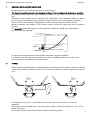
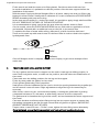
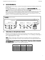
English Manual: Super Power Series 60-80
25/03/2004
Electric Tunnel Thruster
Series 60 Mono Composite 12V 24V
Series 80 Duo Classic and Composite 12V 24V
With Electronic Thruster Controller
INSTALLATION
OPERATION
MAINTENANCE
Serial N°: -----------------------------------------------------Start up date: -------------------------------------------------
IT IS VERY IMPORTANT TO KEEP THIS MANUAL ON BOARD
TECHNOLOGY CENTER – 10 ALLEE FRANCOIS COLI – F 06210 CANNES-MANDELIEU FRANCE
TEL + 33 492 19 60 60 FAX + 33 492 19 60 61
www.max-power.com e-mail: mp@max -power.com
0
English Manual: Super Power Series 60-80
25/03/2004
BEFORE STARTING THE INSTALLATION, IT IS RECOMMENDED TO CAREFULLY READ THE FOLLOWING GUIDE.
Table of Contents
Number
1
2
3
4
5
6
7
8
9
10
11
12
13
14
15
16
17
18
19
20
21
22
23
24
25
26
27
28
29
30
Description
Page
General Installation Guidelines
Tunnel
Propeller Drive Leg, Motor Support
Composite Drive Leg
Electric Motor (12 V)
Propeller (s)
Protection Grill
Electrical Installation
Control System
Control Panel & Thruster Control Box Functions
Control Panel Installation
Battery Requirements
Power Cable Selection
Fuse
Tests
Electrical Measurements
Operation
Alarm(s) Thermal Switch-off
Safety
Maintenance
Composite Leg
Classic Leg
Diagram of Parts
Spare Parts List
Super Power with Controller: Wiring
Connection of Controller to Thruster Motor
Troubleshooting Guide
Warranty Coverage
Distributor Contact List
Warranty Document (to be returned)
2
2-3
3
4
4
4
4
4
5
6
6
7
7
8
8
8
9
9
9
9
10
10
11
12
13
14
15-16
17-18
19-20
21
Your thruster is a high quality technical product and should be treated as such. The employment of
qualified marine personnel, with experience in bow thruster installation, is strongly advised. Where
possible, the boat manufacturer’s architects, design departments and/or shipyards should be
consulted, prior to installation taking place. For any boat requiring official classification, bodies of
approval should also be consulted at the earliest opportunity. In any case, all other bodies,
governmental or otherwise, should be contacted to ensure conformity with legal regulations relating
to the boat in question.
Your thruster should be delivered with the following parts:
Motor, Relay Assembly,
motor coupling & Control
box
Propellers CT60 (1) CT80 (2)
Relay Cover
Motor Support
Drive Leg, Propeller Pin(s)
& Coupling
Safety Stickers x 2 Manual
1
English Manual: Super Power Series 60-80
1
25/03/2004
GENERAL INSTALLATION GUIDELINES
Determining the most efficient position for your thruster:
The tunnel should be placed in the deepest section of the hull and as far forward as possible.
For maximum efficiency the tunnel should be installed no less than 100 mm from the water
line.
Where the boat’s design will not allow for this submersion, any subsequent efficiency deficit
can be partly compensated using a position closer to the bow (to create greater leverage).
Decide on the most suitable configuration for both the tunnel and the electric motor.
Where necessary, the weight of the electric motor should be supported and its position
secured.
The propeller should be centred in the tunnel and should not, under any circumstance,
protrude from the opening.
Water Line
185 mm
Support
As far forward as possible
The area around the thruster should remain accessible, dry and ventilated.
The thruster can draw power from either the starter or auxiliary batteries, but use of the
source closest to the thruster is recommended.
2
TUNNEL
When the final tunnel position is determined (and all dimensions have been checked), mark the
centre of the tunnel’ position and drill a Ø 10 mm hole. Make up a metal compass from 8 mm
rod.
Do not
stratify over
this zone
Do not
stratify over
this zone
Fit compass in to the Ø 10 mm holes and trace the form of the tunnel on to the hull
(elliptical).
After cutting out the elliptic hole , disc the interior surface of the hull, by approx. 10 to 15 cm
around the holes.
The outside surface of the tunnel is then ready to be fibre-glassed.
2
English Manual: Super Power Series 60-80
25/03/2004
Fit the tunnel and mark the areas to be fibre-glassed. Sand these areas inside and out.
In certain installations it is preferable to drill the position of the thruster support before the
installation of the tunnel.
Refit the tunnel. Apply reinforced fibreglass filler to all areas, taking care that you fill the gap
between hull and tunnel. Stratify with a minimum of 8 coats of material and ISOPHTALIQUE
RESINE alternating with mat and roving.
In the areas not accessible (i.e. under the tunnel), it is possible to apply simply reinforced filler.
DO NOT FIBREGLASS THE AREA OF THE MOTOR SUPPORT.
It is recommended to lightly sand down the area where the electric motor is fitted.
On the outside, when the ISOPHTALIQUE RESIN has set, finish with an application of resin
and material, followed with an additional coat on the hull, in the tunnel area.
To optimise the flow of water while sailing, deflectors & a relief should be fashioned.
These can be made up with several coats of reinforced filler in order to obtain the required
hydrodynamic lines.
Relief
Deflector
Once all fibreglass work is complete, apply a coat of epoxy or gel-coat to waterproof the
entire area.
3
PROPELLER DRIVE LEG & MOTOR SUPPORT
The leg’s gasket and the motor‘s support can be used to mark up the drilling position, in
some cases it might be easier, to mark out the position, and drill before the stratification of
the tunnel.
Centre and trace the drilling positions for the leg and its support.
Fit the leg along with the gasket, in the tunnel.
Check general positioning of the propellers.
Small pieces of folded cardboard can be used to check the spacing between the propeller tips
and the tunnel is even all round. Slight adjustment to align the leg in its tunnel may be
necessary.
After checks, remove leg etc, remount the assembly, covering the gasket with a jointing
compound resistant to oil, salt water, et after fitting, remove all access compound.
The gasket must be between the leg and the tunnel, and not between the motor support and
the tunnel.
Care must be taken at all times when fitting the leg into the motor support to ensure that
the mating components are dirt free and covered with a light film of grease. (IMPORTANT:
GRAPHITE GREASE MUST NOT BE USED).
Torque values: screw Ø 8 mm = 30 Nm screw, tighten the two fixing screws alternately.
Once tightened, ensure that the propeller/s turn freely without touching the tunnel.
3
English Manual: Super Power Series 60-80
4
25/03/2004
COMPOSITE DRIVE LEG
The installation of the composite drive leg is identical to that of bronze leg, except for the
following points:
The composite drive leg is lubricated for life
The composite drive leg does not require an anode.
The composite drive leg MUST NOT BE DISMANTLED even partially.
5
ELECTRIC MOTOR
Position the motor on the support:
Insert the shaft of the motor into the slot of the leg (grease before fitting).
Position the motor and tighten screws (30 Nm).
Turn the motor & leg over by hand by turning a mounted propeller .If there is a hard point
then the drive leg is badly positioned in the tunnel creating a bad motor / leg alignment ,this
can cause drive leg shaft failure.
6
PROPELLER (S)
Check that the propellers turn freely and that there is no tight spot. A certain resistance is
normal from the motor.
When all is assembled and all screws are torqued down then continue the installation.
RECOMMENDATION: For prevention of calcium build-up on the propellers shaft, which
would damage the oil seals, we recommend to apply silicon grease to shaft and oil seals
before fitting the propeller(s).
Fit the fixing pins and propellers.
POSITION THE PROPELLERS OPPOSED AND NOT FACE-TO-FACE.
Tighten the fixing screws as recommended for the model:
SUPER POWER SERIES 60 to 125: Allen screw 3 mm must not protrude more than 2 mm out
from the hub of the propeller. If the Allen screw protrudes out more than 2 mm, THE
PROPELLER IS NOT CORRECTLY IN PLACE AGAINST THE PIN.
7
PROTECTION GRILLS
On certain installations which are close to the waterline, it may be necessary to fit protection
grills. However, these grills will modify the thruster performance.
8
ELECTRICAL INSTALLATION
ATTENTION: An incorrect electrical installation will cause rapid deterioration / failure of the
unit. Excessive voltage drop will cause relay and brush failure. Special attention should be
given to the quality, capacity and condition of your batteries, and cable sizes.
REMEMBER: Take care to tighten correctly all electrical connections.
WARNING: Under no circumstances should any inflammable products be stored next to the
electrical components of the thruster.
WARNING: It is essential to install a manual and if possible an electric battery isolator at the
base of the thruster motor supply line .
When using a manual battery isolator it must be, visible, clearly marked & easily accessible.
4
English Manual: Super Power Series 60-80
9
25/03/2004
CONTROL SYSTEM
Install a breaker/isolator in the supply wiring of the thruster control box on the boats’ main
electrical switchboard marked BOW THRUSTER:
This breaker/isolator should ideally be supplied from an independent battery bank, to the one
used for powering the thruster unit.
Advised Method: Controller Supplied from Independent Battery Bank
Control
Panel
C
Co able
nn
ec
to
r
Yachts Main DC Equipment
Breaker Board
6 Wire Control Cable
Yellow
Black
OFF
OFF
OFF
OFF
OFF
OFF
OFF
OFF
ON
ON
ON
ON
ON
ON
ON
ON
Cable
Connector
Blue
Brown
- + - + - + - + - + - + - + - +
Negative
Red
White
8A
Thruster
Control Box
Positive
2 x 2 mm² (Depending on cable length)
Grey
Grey
Black
Red
L/R
+
-
+
+
-
+
-
L/R
+
Independent Battery Bank
for Control Circuit Supply
Thruster Battery Bank
Power Fuse
(12/24V depending on thruster voltage, see "Power Connections")
Electric Battery Isolator
NOTE: Thrusters which are equipped with a “thruster control box” can only be used with
Max Power’s range of control panels as shown in this manual.
The thruster controller can be supplied in either 12V or 24V, depending on the thruster
voltage.
The installer must protect the positive supply cable of the thrusters control box by means of a
fuse as indicated in the above drawing. The size of the supply wires (red & black) depends on
the length of the cable run, the voltage drop in these cables should not exceed 5% of the
nominal battery voltage.
For safety reasons and in order to benefit from all the functions provided by the thruster
controller, an electric battery isolator needs to be installed in the thruster motor’s positive
supply cable.
If an electric battery isolator is not used then simply seal-off the two grey wires coming out of
the control box. It is important to isolate the thruster motor power circuit by means of the
manual battery isolator after having left port & when the manoeuvre is finished, after docking.
Please refer to the drawing “Connection of Controller to Thruster Motor” in the back of this
manual for more detail on the wiring of the controller to the thruster unit.
5
English Manual: Super Power Series 60-80
10
25/03/2004
CONTROL PANEL AND THRUSTER CONTROL BOX FUNCTIONS
To switch the thruster "ON" or "OFF" follow the instructions on the diagrams below.
When switched "ON" the unit will beep once and the green LED in the red push-button
will light up.
When switched "OFF" the unit will beep twice and the green LED in the red push-button
will go out.
The thruster controller provides a time delay between left and right thrust in order to avoid
rapid direction changes, but no delay when thrusting to same side.
If the thruster motor overheats the unit will start beeping, while the green LED will flash, until
the thruster motor has cooled down.
Once the overheat alarm starts, one has 10 seconds of actual thruster use before the unit
automatically shuts down. The unit will then not be able to be switched on again until the
motor has cooled down.
If the thruster unit has not been used for a period of thirty minutes the unit will automatically
switch off. Before switching off automatically the unit will warn you by beeping
once followed by a second beep a few seconds later, after which the unit switches off.
In order to isolate the power circuit of the thruster motor as described in the two points
above one would need to install an electric battery isolator, as advised by Max Power( see
"Wiring Diagram" in the back of this manual for more detail ).
Single Touch Panel:
POWER
POWER
To Switch "ON" or "OFF"
push down both red &
green push-button for one
second.
Red Push-button
with Green LED
Joystick
Red Push-button
with Green LED
Green
Push-button
Single Joystick Panel:
POWER
Joystick
Red Push-button
with Green LED
11
To Switch "ON" or "OFF"
push down the red pushbutton, while pushing
joystick to the right for
one second.
Double Joystick Panel:
To Switch "ON" or "OFF"
push down the red pushbutton, while pushing
joystick to the right for
one second, for both bow
and stern thruster.
Joystick
Red Push-button
with Green LED
CONTROL PANEL INSTALATION
Control panels should be protected from the natural elements while the thruster is not in use.
Install the control panel(s) in easily accessible positions, without obstructing the main engine
and/or steering controls.
When fixing the panel with the black stainless steel screws, make sure to install the pre-cut
rubber seal, as supplied with the panel, ensuring that it is in the correct place.
IMPORTANT: Only when totally finished and satisfied with wiring and positioning of the unit,
clip-on the face panel/cover.
Please note that panels are only fully waterproof from the front, if installed correctly. However
the area behind the dashboard should be kept dry to avoid the risk of oxidation of the cable
connecter contacts.
For full installation instructions of the control panels please refer to “Installation Guidelines “
as supplied with each control panel.
6
English Manual: Super Power Series 60-80
12
25/03/2004
BATTERY REQUIREMENTS
CAUTION: refer to the maker’s technical characteristics (capacity and starting current) of the
battery used.
Example: Exide Maxxima 900, 12 volts, capacity 55 Ah / starting current 800 CCA.
The higher the CCA the more suitable the batteries are, large capacity batteries with a low
CCA may be inferior to much smaller battery’s with a higher CCA .
NOTE :in the case of dedicated batteries charged by alternator, the reference for the charge
must be taken after the diode-splitting block (if in doubt, consult a marine electrician).
Thruster performances are quoted with a minimum 22 Volts at the terminals of a 24 Volts
motor or 11 for 12 volts (thruster running, boat in water).
Power Connections
_
+
Electric Battery isolator
recomended (option)
12v 55 Ah
12v 55 Ah
12v 55 Ah
-
+
-
+
12v 55 Ah
-
+
-
+
-
-
+
13
Fuse
+
12v 55 Ah
12v 55 Ah
(Negative)
A1
L/R
L/R
+
12v 55 Ah
Thruster Power supply
24 V 55 Ah
-
12v 55 Ah
Thruster Power supply
12 V 110 Ah
+
Thruster Power supply
24 V 110 Ah
POWER CABLE SECTIONS ( BATTERIES TO RELAY )
Measure the total length (the shortest and most direct route possible) of the main power
cables between the batteries and the motor power relay ( + & - in drawing ) .Total length is
the + length added to the - length .
NOTE: when choosing your cable sections do not forget to take into consideration the
ampacity rating of the cables concerned. These cables must be of the highest thermal class
available.
The following chart takes into account only permissible voltage drop, it does not represent
the ampacity rating.
The ampacity rating is specific to each cable manufacturer.
Cable lengths
to and from
For 5 m (2,5 x 2)
For 10 m (5 x 2)
For 15 m (7,5 x 2)
For 20 m (10 x 2)
Series 60 / 80 Series 60 / 80
12 V
24 V
50 mm²
35 mm²
70 mm²
50 mm²
95 mm²
70 mm²
120 mm²
95 mm²
7
English Manual: Super Power Series 60-80
14
25/03/2004
FUSE
Sizing of fuses for overcurrent protection are a function of the cable sizes in the circuit, not the
amperage drawn by the appliance (thruster motor) in the circuit. The current carrying
capability (ampacity) of this cable is determined by referring to the appropriate cable
datasheet, and then a fuse is chosen with a ratio no higher than this (it can be lower). If there
is not an exact match between cable ampacity and available fuse ratings, an overcurrent
device (for example a fuse) with a rating of up to 150% of the ampacity of the cable can be
used, but that’s the limit.
After choosing the required fuse size verify if thruster motor current(given below) is not to big
for the fuse, thus causing nuisance blowing of the fuse. If fuse is found to be to small for
motor current a bigger cable and fuse size need to be used.
15
Series/V
Amps
Series/V
Amps
60/12
80/12
415
490
60/24
80/24
240
285
TESTS
UNDER NO CIRCUMSTANCES SHOULD THE THRUSTER OR ITS MOTOR BE ACTIONED WITH
THE BOAT OUT OF THE WATER.
THE TESTS MUST BE CARRIED OUT WITH THE BOAT IN THE WATER, AND THE BATTERY (IES)
AT 100% CHARGE; ENGINES RUNNING AND THE CHARGING SYSTEM AS PER NORMAL
OPERATION.
16
ELECTRICAL MEASUREMENTS
In normal “use” configuration for, i.e. thrusters running, yacht in the water, with fully charged
batteries receiving a charge (alternator). Electrical measurements should be made at the
following points:
At the batteries
At the battery cut off switch
At the fuses
At the motor’s connections
At supply arriving at thrusters control box
These measurements will able you to detect voltage drop. The voltage read should be of
approximately 11 volt for a 12-volt system and 22 volts for 24-volt system.
Should the voltage measured be too low the following points need to be checked:
Insufficient battery capacity
Bad battery quality
Insufficiently charged batteries
Incorrect cable sections
Badly tightened connections.
8
English Manual: Super Power Series 60-80
17
25/03/2004
OPERATION
With the control system breaker/isolator and manual battery isolator switched on:
Switch on control panel, as described previously in manual.
Push red button or incline joystick to the left, boat moves to the left.
Push green button or incline joystick to the right, boat moves to the right.
If, during tests the boat moves in the wrong direction, change the blue and the brown
wires around on your power relay.
When manoeuvring take into consideration the inertia effects, remember the boats
momentum continues after you release the joystick /button, therefore remember to release
the control prior to reaching your desired position.
Care must be taken not to use the thruster in areas swimming areas or areas of floating
debris.
Maximum running time: S2-3 min. rating (depending on room temperature).
18
ALARM(S) OR THERMAL SWITCH-OFF
The electric motor of the thruster is fitted with a thermal switch as standard. If the thruster
motor overheats the buzzer in the control panel will start beeping, while the green LED in the
red-push button will flash, until the thruster motor has cooled down again.
Once the overheat alarm starts, one has 10 seconds off actual thruster use before the unit
automatically shuts down. The unit will then not be able to be switched on again until the
motor has cooled down.
19
SAFETY
Switch off means on both the DC equipment panel ( control supply ) & the thruster power
battery isolator ( thrusters supply ) after having left port & when the manoeuvre is finished,
after docking. Under no circumstances should any inflammable products be stored next to
the electric components of the thruster. Care must be taken not to use the thruster in
swimming areas or at any time when people maybe in the water close to the thruster.
WARNING: Never temper with thruster/thruster turbine, if not 100% sure that both control
and power circuits have been isolated, except if taking electrical measurements on the
thruster motor or relay.
20
MAINTENANCE
The SUPER POWER requires minimum maintenance:
Check regularly the condition of the batteries Voltage drop is the most frequent cause of rapid
deterioration of the relay and motor brushes.
Carry out a regular check of the batteries, connections and power cables.
Remove motor and clean out dust from motor-brushes with compressed air. Replace brushes
if found to be worn by more than 70%.
The electric motor must be kept dry and aerated.
Check relay contact surfaces and replace if necessary.
9
English Manual: Super Power Series 60-80
21
25/03/2004
COMPOSITE LEG
The composite drive leg is lubricated for life and does not require changing of oil.
The composite drive leg does not require an anode.
The composite drive leg must not be disassembled, even partially.
Paint leg and propellers with antifouling (make sure that they were well prepared and primer
has been used).
Always keep the propellers and tunnel clean.
For prevention of calcium build up on the drive shafts, which would damage the oil seals,
before fitting the propeller(s), cover drive shaft and the oil seals stainless steel cover with
silicon grease. This should be done on an annual basis after cleaning of outside of leg.
Do not use aggressive solvents as they might damage drive leg seals.
If drive leg oil seals are found to be worn, replace drive leg with exchange unit.
22
CLASSIC LEG
Check the oil in the leg every year, and change if necessary (oil drain plug under the anode copper joint should be changed). See chapter PROPELLER, LEG, in the installation manual.
The anode should be frequently checked and changed when necessary (At least every year).
When the boat is ashore, check for evidence of fishing line, etc… in the propellers.
For prevention of calcium build up on the drive shafts, which would damage the oil seals,
before fitting the propeller(s) cover drive shaft and oil seals, with silicon grease. This should be
done on an annual basis after cleaning of outside of leg.
Do not use aggressive solvents as they might damage drive leg seals.
If drive leg oil seals are found to be worn, replace drive leg with exchange unit.
Always keep the propellers and tunnel clean.
Paint leg and propellers with antifouling (make sure that they were well prepared and primer
has been used).
Do not paint the anode.
10
English Manual: Super Power Series 60-80
25/03/2004
60 MONO composite
80 DUO composite
80 DUO classic
3
1
L/R
4
46
PWR
POWER
MP - STC
ISO
5
PNL
L/R
2
6
HEAT
RLYS
7
13
45
44
43
DUO classic
16
17
18
19
20
21
22
23
36 34 32
31 30
29 28 27
25
24
35 33
37
38
39
40
11
English Manual: Super Power Series 60-80
25/03/2004
N°
SERIES 60 MONO & 80 DUO COMPOSITE & CLASSIC
60
COMPO
80
CLASSIC
80
MPSP
MPSP
MPSP
MPSP
MPSP
DESCRIPTION
C412
C424
0512
0524
C512
12V
24V
12V
24V
12V
1
Cover
2
Relay support
3
Connecting strip
4
Complete 12V relay
4
Complete 24V relay
5
12V Motor
5
24V Motor
1,2,3,4
12V motor + relay
,5
1,2,3,4
24V motor +relay
,5
6
Motor fixing bolt
7
Motor drive pin
13
Composite Motor
Support
16
Drive shaft seal
17
Drive shaft
18
Upper shaft bearing
19
Lower shaft bearing
20
Upper gear
21
Clips
22
Composite Leg fixing
bolts
22
Classic Leg fixing bolts
23
Fibre joint l1,5 mm
24
Leg housing
25
Propeller D 185
27
Propeller pin
28
Oil seal output shaft
29
Screw Cap
30
Double propeller shaft
31
Shaft key
32
Lower gear
33
Shim Set
34
Propeller shaft bearing
35
O' ring
36
Cap
37
Copper washer
38
Drain plug
39
Anode
40
Anode screw
43
Complete Bronze Leg
44
Composite leg Duo
45
Composite leg Mono
46
Thruster Control Box
1
1
2
1
1
1
2
1
1
2
1
1
1
1
2
2
1
1
1
1
1
1
1
1
1
1
1
1
1
1
1
1
4
1
4
1
1
1
1
1
1
1
1
1
1
1
1
1
2
1
1
2
2
2
4
1
1
1
2
2
2
2
1
1
1
1
1
1
1
1
2
1
1
4
1
1
1
1
2
1
1
1
1
4
1
1
1
1
2
COMPO
MPSP
C524 REFERENCES
24V
2
1
1
2
2
2
4
1
1
1
2
2
2
2
1
1
1
1
1
1
MP05 2021
MPOP 5212
MPOP 3154
MP05 3024
MP05 3026
MP053030
MP053031
MP058312
1
MP058324
4
1
1
MPOP 5241
MP05 8031
MP05 8035
2
2
MPOP 2030
MPOP 4060
MPOP 5250
MPOP 5251
MPOP 5051
MPOP 5280
MPOP 4130
1
1
2
2
2
2
1
1
1
1
4
1
1
MPOP 5340
MPOP 2060
MPOP 5270
MPOP 8080
MPOP 5221
MPOP 2070
MPOP 5320
MP08 5020
MPOP 5290
MPOP 5061
MPOP 5350
MPOP 5260
MPOP 2040
MPOP 53 80
MPOP 2050
MPOP 5300
MPOP 5390
MPOP 5311
MP08 8040
MP08 8100
MP05 8100
MPOP5701
12
English Manual: Super Power Series 60-80
25/03/2004
Advised Method: Controller Supplied from Independent Battery Bank
Control
Panel
C
Co able
nn
ec
to
Yachts Main DC Equipment
Breaker Board
r
6 Wire Control Cable
Yellow
Cable
Connector
Black
OFF
OFF
OFF
OFF
OFF
OFF
OFF
OFF
ON
ON
ON
ON
ON
ON
ON
ON
Blue
Brown
- + - + - + - + - + - + - + - +
Negative
Red
White
Black
Red
Positive
Grey
Grey
Thruster
Control Box
2 x 2 mm² (Depending on cable length)
8A
L/R
+
-
+
+
-
+
-
L/R
+
Independent Battery Bank
for Control Circuit Supply
Thruster Battery Bank
Power Fuse
(12/24V depending on thruster voltage, see "Power Connections")
Electric Battery Isolator
Optional Method: Controller Supplied from Thruster Battery Bank
Control
Panel
C
Co able
nn
ec
to
r
6 Wire Control Cable
Yellow
Cable
Connector
Black
Blue
Brown
Negative
Red
White
L/R
L/R
Black
+
8A
Black
Grey
Grey
Thruster
Control Box
Red
Positive
Power Fuse
+
-
+
+
-
Thruster Battery Bank
(12/24V depending on thruster voltage, see "Power Connections")
Electric Battery Isolator
Super Power with Controller:
Wiring Diagram
JC
02
17/03/2004
13
Black
Blue
L/R
Black
Blue
L/R
Yellow
Yellow
Black
Brown
HEAT
PWR
Pos.
ISO
Neg.
RLYS
PNL
POWER
Grey
Grey
MP - STC
Thruster
Control
Box
NOTES:
Cable Connector
To Control Panel
17/03/2004
JC
02
Connection of Controller
to Thruster Motor
1. The installer must protect the positive supply cable
by means of a fuse as indicated. The size of the
supply wires( red & black) depends on the length
of the cable run and the voltage drop in these
cables should not exceed 5% of the nominal battery
voltage.
2. Install an electric isolator/switch, in the supply of
the thruster control box, on the boats main
electrical switch board, marked "Bow Thruster".
This breaker or switch should ideally be supplied
from a source independent to that used for the
thruster. See "Wiring Diagram for more detail.
White
Red
Brown
Blue
Black
Yellow
To Electric Battery Isolator
Black
Red
+
8A
Fuse
Control
Circuit
Supply
(Note 1)
English Manual: Super Power Series 60-80
25/03/2004
14
English Manual: Super Power Series 60-80
25/03/2004
TROUBLE SHOOTING GUIDE
Before contacting your nearest distributor please check the following list for probable causes
PROBLEM
PLEASE CHECK
THRUSTER NOT OPERATING
Check correct electric motor voltage
check cables
No main power
check batteries power on/off switch
check batteries
check fuse
Control Panel
check if panel is switched on (green LED on?)
Relay not functioning
check wiring and signal relay
Relay clicking
Insufficient voltage – check batteries
RELAY FAILURE
Incorrect or damaged batteries
Control batteries for size and condition
(see manual for recommended size)
Excessive voltage drop
Attain a min 10.8V at relay when operating 12V system
Attain a min 21.6V at relay when operating a 24V system
Battery cable section too small – see manual.
Voltage losses at cable connections
LACK OF THRUST
Low battery power
check battery condition and charge
Missing or damaged propeller
check propellers
PROPELLORS TOUCHING TUNNEL
Drive leg incorrectly aligned in tunnel
Align drive leg in tunnel
Modify fixing holes in necessary
STEEL TUNNELS
Incorrect mounting of electric motor
check tunnel Dia inside and outside are as recommended
15
English Manual: Super Power Series 60-80
25/03/2004
Trouble shooting guide cont..
ELECTRIC MOTOR DRIVE PIN BREAKAGES
Tunnel thickness too thin
Fit a joint under motor support to attain correct
(less than 6mm)
thickness
Debris in propellers / tunnel
Clear obstruction, check drive leg input shaft for free
running, replace drive pin
DRIVE LEG INPUT SHAFT BREAKAGE
Thruster motor support not parallel
Reface tunnel ensure interior & exterior are parallel
to drive leg (probably due to excess fibreglass added
to tunnel)
Correct tightening of the fixing bolts electric motor
support/drive leg
16
English Manual: Super Power Series 60-80
25/03/2004
WARRANTY COVERAGE
Introduction
The purpose of this document is to set out the terms of warranty cover offered in relation to products
purchased by the End User from Max Power or its approved network of resellers. This document will adhere
to the following format:Section 1
Section 2
Section 3
Section 4
Section 5
Section 6
Section 7
1)
Definitions
Period of Coverage
Warranty Registration
Warranty Terms
Warranty Exclusions
Procedural Guidelines
Service Centres
Definitions
Authorized Repair Number – The number given by Max Power on reporting a fault with your thruster
Dealer – An authorized Max Power sales centre
End User – The boat supplied with supplied equipment and the owner thereof
Installer – The authorized centre responsible for the installation of your thruster
Manufacturer – supplier of the equipment under warranty
Pleasure Craft – Vessels used for owner’s personal use that have no commercial use
(i.e Charter boats or work boats)
Resellers – Max Power approved distributors and dealers
Serial Number – Number in upper right hand corner of Warranty document
Supplier – The manufacturer (Max Power)
Warranty – The terms and conditions that are covered by the manufacturer
2)
Period of Coverage
The equipment manufactured by the Supplier is guaranteed to be free from defective workmanship,
components and materials under normal usage conditions for a period of two years from the date of
purchase by the End User. This warranty is transferable to subsequent owners of this equipment during the
period of coverage.
3)
Warranty Registration
Register your purchase now to receive free extended warranty coverage. This can be done using one of the
following methods (NB. proof of purchase must be included to establish that equipment is still under
warranty):
a)
b)
The quickest and easiest method to register your warranty is to fax the attached installation check
list and warranty registration to the Manufacturer
(Fax: +33 4 92 19 60 61)
Mail in your warranty registration document, please ensure that you make a copy before sending
it. (10 Allée F Coli, 06210 Cannes-Mandelieu, France)
17
English Manual: Super Power Series 60-80
25/03/2004
Warranty Document Cont.
4)
Warranty Terms
If the material is used for anything other than for pleasure craft, the guarantee is limited to a six-month
period.
Year 1 All factory testing, diagnosis, repairs and replacements are performed at no charge to the End
User. All parts and up to two hours of labour are covered for repairs and replacements conducted in
the field.
Year 2 -
All factory testing, diagnosis, repairs and replacements are performed at no charge to
the End User. This excludes any damage or faults occurring from normal wear and tear on the
following items: engine, oil seals, relay contacts(If warranty is registered within the 3 month period
following installation)
5)
Warranty Exclusions
Damage due to modifications or installation contrary to published specifications
Cost of hauling the boat
Damage due to repairs performed by an unauthorized service centre
Damage due to lack of normal maintenance services
Damage due to water
Parts replaced due to normal wear and tear
Repairs performed without knowledge of manufacturer (please contact dealer to receive Repair Authorization
Number)
Tampering of equipment by the End User
Cost of travel to and from the job site
Cost of economic loss, including injury to any person, damage to property, loss of income or profit,
communication, lodging, inconvenience
Consequential damage due to failure, including those arising from collision with other vessels or objects
6)
Procedural Guidelines
PLEASE VIEW THE TROUBLE SHOOTING LIST TO ASCERTAIN OR SOLVE ORIGIN OF PROBLEM PRIOR TO
CONTACTING THE DEALER/INSTALLER
1)
2)
3)
4)
5)
Contact your dealer/installer to report the problem.
a. If you do not know who this is contact the nearest Max Power distributor
b. If you are in foreign waters please contact the nearest Max Power distributor
Ensure you have your serial number and model number to hand (top right hand corner of
warranty)
Dealer/Installer will come to site to decipher the cause of the fault
If the cause of fault is due to a manufacturing problem the dealer will contact Max Power to
receive Repair Authorization Number.
If the problem is due to an installation error please contact your installer.
IF POSSIBLE: PLEASE TAKE PHOTOGRAPHS OF THE THRUSTER TO SHOW PROBLEM
The warranty as outlined above is only applicable to MaxPower manufactured thrusters and optional
equipment as used in marine pleasure industry. The supplier holds the exclusive right to test the
product and determine whether it is defective.
18
English Manual: Super Power Series 60-80
25/03/2004
DISTRIBUTOR CONTACT LIST
SOUTHERN EUROPE
CYPRUS
CYPRUS
OCEAN MARINE EQUIPMENT LTD
Limassol
Tel: + 357 53 69 731
Fax: + 357 53 52 976
Email: [email protected]
FRANCE & MONACO
TUTI MARE TRADING
Limassol
Tel: + 357 25 431 313
Fax: + 357 25 431 300
Email: [email protected]
GREECE
REYA
Cannes La Bocca
Tel: + 33 493 90 47 00
Fax: + 33 493 47 42 57
Email: [email protected]
ALEX MARINE
Piraeus
Tel +30 10 41 29 539
Fax: + 30 10 41 12 932
Email: [email protected]
FRANCE
SLOVENIA & CROATIA
ACCASTILLAGE BERNARD
Mandelieu
Tel: +33 4 93 90 47 47
Fax: +33 4 93 90 47 53
[email protected]
ITALY
ANORTI
Ljubljana / Zagreb
Tel: +386 1 544 6436 / +385 98 1 896 770
Fax: +386 1 5446435 / +358 23 386 075
[email protected] / [email protected]
PORTUGAL
Siemens VDO Trading Srl.
Novate Milanese(MI)
Tel: + 39 0235 6801
Fax: + 39 0238 204 339
Email: [email protected]
SPAIN
PLASTIMO PORTUGAL (SIROCO)
Lisbon
Tel: + 351 21 362 04 57
Fax: + 351 21 362 29 08
Email: [email protected]
TURKEY
ACASTIMAR
Cambrils Tarragona
Tel: + 349 77 36 2118/9074
Fax: + 349 77 36 2687
Email: [email protected]
HUNGARY
DERYA MARINE SERVIS
Marmaris-Muola
Tel: 90 252 412 52 25
Fax: 90 252 411 33 61
Email: [email protected]
ISRAEL
MIMOKER
Budapest
Tel +36 127 42639
Fax: +36 1200 54 92
Email: [email protected]
YAMIT
Tel Aviv
Tel: + 972 3 5271 779
Fax: +972 3 527 1031
Email: [email protected]
NORTHERN EUROPE
DENMARK
GERMANY
PALBY MARINE
Vejle
Tel: + 45 75 88 13 11
Fax: + 45 75 88 17 01
Email: [email protected]
SIMRAD
Schieswig
Tel: + 49 4621 961 30
Fax: + 49 4621 9613 28
Email: [email protected]
ICELAND
GERMANY
VELASALAN
Reyhavik
Tel: +354 580 5312
Fax: +354 580 5301
[email protected]
NAVIMO Deutschland
56325 Lorient
Tel : +49 6105 92 10 09/10
Fax : +49 6105 92 10 11
[email protected]
19
English Manual: Super Power Series 60-80
25/03/2004
FINLAND
HOLLAND
MASTERVOLT FINLAND
Raisio
Tel: +358 2 4339990
Fax: +358 2 4350085
Email: [email protected]
NORWAY
KEMPER EN VAN TWIST
Dordrecht
Tel: + 31 078 61 30 155
Fax: + 31 078 61 36 746
Email: [email protected]
SWEDEN
PROGRESS INGENIORFIRMA AS
Kjeisaas
Tel: + 47 22 02 79 00
Fax: + 47 22 02 79 01
Email: [email protected]
PLASTIMO NORDIC
Henan
Tel: + 46 304 360 60
Fax: + 46 304 307 43
Email: [email protected]
UK
UK
PLASTIMO UK
Eastleigh, Hampshire
Tel: + 44 870 751 4666
Fax: + 44 870 751 1950
Email: [email protected]
AR PEACHMENT
Norfolk
Tel: + 44 1603 714 077
Fax: + 44 1603 714 211
Email: [email protected]
AMERICAS
ARGENTINA
CANADA
BARON SRL
Buenos Aires
Tel: + 54 11 4580 55 56
Fax: + 54 11 47 46 16 96
Email: [email protected]
BRAZIL
REKORD MARINE ENTERPRISES LTD
Vancouver
Tel: 1604 325 52 33
Fax: + 1604 325 03 26
Email: [email protected]
USA
SAILING PRODUCTS
Rio de Janeiro
Tel: + 55 21 494 7222
Fax: + 55 21 494 7223
Email: [email protected]
SCANDVIK
Vero Beach, Florida
Tel: 1 561 567 28 77
Fax: +1 561 567 91 13
Email: [email protected]
SOUTH EAST ASIA
AUSTRALIA & SINGAPORE
NEW ZEALAND
OCEANTALK
Sydney
Tel: + 612 9981 9500
Fax: + 612 9981 9555
Email: [email protected]
CHINA
POWER & MARINE
Wiri Auckland
Tel: + 64 9 914 55 55
Fax: + 64 9 914 55 88
Email: [email protected]
SINGAPORE
RONSIL DEVELOPMENT
Hong Kong
Tel: + 852 2834 1633
Fax: + 852 2834 0201
Email: [email protected]
OCEANTALK ASIA
Singapore
Tel: + 65 6543 4041
Fax: + 65 6543 4042
Email: [email protected]
CHINA
Holylight Trading
Hong Kong
Tel: +852 2834 7048
Fax: 852 2543 6156
[email protected]
MAX POWER - 10 ALLEE F COLI - 06210 MANDELIEU-CANNES – FRANCE - TEL : + 33 4 92 19 60 60
FAX : + 33 4 92 19 60 61 - EMAIL : [email protected] - WWW.MAX-POWER.COM
20
English Manual: Super Power Series 60-80
25/03/2004
Serial N°:
WARRANTY FORM
VERY IMPORTANT
Please complete this form and fax a COPY to Max Power with a copy of the installation invoice or
the invoice of the yacht/boat in order for the warranty to come into effect.
To Be Completed by Owner:
Name of Owner:…………………………….
Contact No. :……………………….………….
Address: ……………………………………..
E-mail: …………………………………………
Country:……………Postcode: …………….
Name of Skipper:……………………………
Contact No. :…………………………………..
Date: …………………………………………..
Signature of Owner: ………………………...
To Be Completed by Installer:
Installation Details:
Thruster Model :……………………………
Electric/Hydraulic :…………………………….
Date of Installation :………………………..
Date of Launching Boat : ……………………...
Type and model of Boat : ………………….
Builder:………………… Build Year: ………
Pleasure or Commercial craft?:…………….
Sail or Motor: …………. Rig:……………….
Navigates at Sea or River or Canals?………
Hull construction material :…………………….
L.O.A. :………………L.W.L. :……………
Beam :………………… Free Board:…………..
Displacement Weight at Full Load: :………
Height & Length of Superstructure:……………
Tunnel Diameter, Thickness, Material & Length: ………………………………………………….
If Electric, Battery Type, Size & Number: ……………………………………………………………
Installation Checks:
Before Operating Thruster
While Operating
Thruster
Electrical: Voltage at Batteries
…………………………..
………………………….
Voltage at Thruster Motor
…………………………..
…………………………
Charge at Alternator in Amps …………………………………………………………
Ampere in Motor Power Circuit ………………………………………………………...
Mechanical: Verify if drive coupling between motor and drive leg is correctly tightened:..Yes / No
Verify if all cable connections is sufficiently tightened:……………...………...Yes / No
If hydraulic verify all hydraulic connections: ………………………………......Yes / No
Thruster installation tested and working correctly: ………………………………………….Yes / No
Important: Refer to installation manual for full installation details.
Name of Installer: ………………………….
Signature:.……………………….
PLEASE RETURN BY FAX: + 33 4 92 19 60 61
TO GAIN YOUR EXTRA WARRANTY COVERAGE
21