1
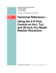
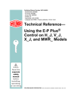
Published Manual Number: MQCJVO01EN
•
•
•
•
•
•
•
Specified Date: 20090831
As-of Date: 20090831
Access Date: 20091001
Depth: Detail
Custom: n/a
Applicability: CJV CJH CJF CJX
Language Code: ENG01, Purpose: publication, Format: 1colA
Operator Guide—
Washer-extractor
Models with E-P Plus®
and E-P Express®
Controls
PELLERIN MILNOR CORPORATION
POST OFFICE BOX 400, KENNER, LOUISIANA 70063 - 0400, U.S.A.
Applicable Milnor® products by model number:
30015T5J
36026V5J
MWR18J448040F7J
30015V7J
36026V7J
30022H7J
68036F5B
30022T5J
36026X8J
30022H8J
30010G5X
30022V6J
42026V6J
30022F8J
30015G5X
30022X8J
42026X7J
36030F8J
30015T5X
36021V5J
42030V6J
42032F7J
30022T5X
36021V7J
42032X7J
48040F7B
MWR18X4-
Table of Contents
Table of Contents
Sections
Figures, Tables, and Supplements
Chapter 1. Description of Controls
1.1. Operator Controls on E-P Plus® and E-P Express® Models
Figure 1: Typical Control Panel
(Document BICJHF01)
Chapter 2. Normal Operation
2.1. Normal Machine Operation (Document BICJVO03)
2.1.1. Start Here for Safety
2.1.2. Check Switch Settings
2.1.3. Load the Machine
2.1.4. Select and Start a Formula
2.1.5. Monitor Operation
2.1.6. How to Terminate a Running Formula
2.1.7. How to Restart after Losing Power
2.1.8. Unload the Machine
Supplement 1: The Power-up Safety Delay
Chapter 3. Correcting Errors
3.1. Error Messages During Normal Operation
(Document
BICJHT04)
PELLERIN MILNOR CORPORATION
Chapter 1. Description of Controls
Chapter 1
Description of Controls
BICJHF01 (Published) Book specs- Dates: 20090831 / 20090831 / 20091105 Lang: ENG01 Applic: CJV CJH CJF CJX
1.1. Operator Controls on E-P Plus® and E-P Express® Models
This document describes the user controls during normal machine operation. For additional
information on other controls shown in Figure 1, see the reference manual.
PELLERIN MILNOR CORPORATION
Chapter 1. Description of Controls
Figure 1: Typical Control Panel
Control Panel for E-P Plus® and E-P Express® Models
Legend
1.
2.
3.
4.
5.
6.
7.
8.
9.
10.
11.
12.
Start button
Run/Program keyswitch
Run Indicator light
Scroll Down button
Display
Scroll Up button
Next button
Signal Cancel button
Operator Signal light
Manual Mode button
Terminate button
Unlock Door button
.
Display or Action
Explanation
\
When the display says Run Formula, press this button to start the
formula.
B/P
During normal operation, the Run/Program keyswitch must be
set to B. This is the automatic position.
v/w
Use the Scroll Up and Scroll Down buttons to select the desired
formula.
y
The Next button is not used during normal operation.
x
The Signal Cancel button silences the operator signal that
sounds when a formula completes normally. Also, if an operator
signal is programmed with a chemical injection, add the
chemical and press this button to resume operation.
`
The Manual button is not used during normal operation.
z
The Terminate button cancels all remaining steps in the current
formula and starts the shutdown procedure for the machine. The
formula can not be resumed.
'
The Unlock Door button allows you to open the door if all other
safety conditions are met.
— End of BICJHF01 —
PELLERIN MILNOR CORPORATION
Chapter 2. Normal Operation
Chapter 2
Normal Operation
BICJVO03 (Published) Book specs- Dates: 20090831 / 20090831 / 20091105 Lang: ENG01 Applic: CJV CJH CJF CJX
2.1. Normal Machine Operation
2.1.1.
Start Here for Safety
This document is designed to remind the person operating this washer-extractor what is required
to operate this machine. Do not attempt to operate this machine before a trained operator has
explained the details to you.
DANGER 1 : Multiple Hazards—Careless operator actions can kill or injure personnel,
damage or destroy the machine, damage property, and/or void the warranty.
CAUTION 2 : Electrocution and Electrical Burn Hazards—Contact with electric power
can kill or seriously injure you. Electric power is present inside the cabinetry unless the main
machine power disconnect is off.
• Do not unlock or open electric box doors.
• Know the location of the main machine disconnect and use it in an emergency to remove
all electric power from the machine.
• Do not service the machine unless qualified and authorized. You must clearly understand
the hazards and how to avoid them.
2.1.2.
Check Switch Settings
Display or Action
Explanation
B
Check that the run/program keyswitch is at B.
:
Check that any emergency stop switches are in the out position.
m/M
Check that the master switch, if provided, is at M.
Supplement 1
The Power-up Safety Delay
Some Milnor® washer extractors do not use a speed sensing device to verify that the basket has
stopped rotating. Therefore, when power is first applied to the machine, at least 80 seconds
must elapse before any further operations can be attempted. This provides sufficient time for
the basket to coast to a complete stop if power was lost while the machine was in a high speed
extract and restored before the basket stopped.
PELLERIN MILNOR CORPORATION
Chapter 2. Normal Operation
2.1.3.
Load the Machine
Load the machine to the rated capacity and securely close the loading door.
2.1.4.
Select and Start a Formula
Display or Action
Explanation
This is the Run Formula display. From this display, you can
disconnect power from the machine without risking damage to
electronic parts, or you can select a formula to run.
RUN FORMULA
00 OK TO POWER OFF
v/w
RUN FORMULA
07 FORMULA NUMBER 07
\
RUN FORMULA
DOES NOT EXIST
indexes forward/backward through the 30 formulas.
Example display: Formula 07 selected for running
starts the machine with the selected formula.
indicates that the formula selected for running has not been
programmed. This display appears for three seconds.
PELLERIN MILNOR CORPORATION
Chapter 2. Normal Operation
2.1.5.
Monitor Operation
Display or Action
Explanation
23:04 F02S01 02:37
TEMP A168/D170 LEV 1
These two displays alternate during normal operation on some
E-P Plus® models. E-P Express® models display other data
about the step, but not bath temperature data.
23:04 STEP 01 02:37
TEMP A168/D170 SPD 0
23:04
F02S01
02:37
STEP01 is the current step.
EXTRACT indicates that the machine is extracting the goods.
TIMEHALT indicates that the timer is stopped for a chemical
injection. The chemical supply equipment must be properly
installed for this feature to work.
TEMP A168/D170 LEV 1
Temperature in this E-P Plus® machine is measured in degrees
Fahrenheit or Celsius, according to machine configuration.
A168 indicates that the current achieved temperature is 168
degrees. Temperature is displayed only if machine is equipped
with and configured for temperature control.
D170 indicates that the desired temperature for this step is 170
degrees. Temperature is displayed only if the machine is
equipped with and configured for temperature control.
LEV 2 indicates that the bath level achieved is Level 2.
SPD 0 indicates the bath speed for this step.
SPD 0
LEV 2
WAIT FOR LEVEL 2 H indicates that Level 2 is programmed
for this step, but is not yet achieved. The H indicates that the hot
water valve is open; C indicates cold water, and 3 indicates extra
water.
CHEM 03 is displayed when Chemical 03 is being injected. The
number for each chemical (up to five may be connected) is
displayed as the chemical is injected.
FINAL EXTRACT indicates that the step in progress is the final
step of the wash formula.
2.1.6.
How to Terminate a Running Formula
Display or Action
Explanation
z
PELLERIN MILNOR CORPORATION
Cancels the current formula and returns the machine to the Run
Formula display (see Section 2.1.4 “Select and Start a
Formula”).
Chapter 2. Normal Operation
2.1.7.
How to Restart after Losing Power
The control remembers the formula and step it was executing if power fails or if the wall
disconnect is turned off while the machine is operating in automatic mode.
Display or Action
Explanation
PRESS START TO RUN
STEP xx - FORMULA yy
\
On most machine models, this display appears when power is
restored. The formula and step which were in progress when
power was interrupted are shown.
Resumes the formula at the displayed formula and step. If the
outage occured in a bath step, level and temperature (if
commanded) must again be satisfied, even if these were already
satisfied before power was lost. Any commanded chemicals will
be injected again.
If the outage occured during the drain part of a bath step, the
bath step will be repeated, then followed by the next commanded
step.
If the outage occured during an extract step, the previous bath
will be repeated before the extract step begins.
2.1.8.
Unload the Machine
DANGER 3 : Entangle and Sever Hazards—Contact with goods being processed can
cause the goods to wrap around your body or limbs and dismember you. The goods are normally
isolated by the locked cylinder door.
• Do not touch goods inside or hanging partially outside the turning cylinder.
When the formula ends or is terminated, the cylinder coasts for 25 seconds if the last step was a
bath step. If the last step was an extract, the coast time may be as much as 180 seconds. Do not
attempt to open the door early.
Display or Action
Explanation
display during the last 15 seconds of coast, or during the entire
coast time if the formula was manually terminated.
UNLOCKING THE DOOR
PLEASE WAIT
At the end of the coast time, the operator alarm sounds.
WAITING TO UNLOAD
U
x
Silences the operator alarm. The door unlocks so you can unload
the machine.
— End of BICJVO03 —
PELLERIN MILNOR CORPORATION
Chapter 3. Correcting Errors
Chapter 3
Correcting Errors
PELLERIN MILNOR CORPORATION
Chapter 3. Correcting Errors
BICJHT04 (Published) Book specs- Dates: 20090831 / 20090831 / 20091105 Lang: ENG01 Applic: CJV CJH CJF CJX
3.1. Error Messages During Normal Operation
If an error message appears on the bottom line of the display while the machine is running, the
timer shown on the top line will stop counting. When the error is corrected, the timer resumes
counting down. To troubleshoot most errors, suspend the formula in progress and turn power off.
Do not terminate the formula if it is to be resumed after the error is corrected. See the reference
manual for more information.
Display or Action
Explanation
LEVELS STILL MADE
The microprocessor is still receiving information that a level is
made just before or during an extract step, or immediately before
the fill for a bath step. This error is self-clearing when level is
lost.
TOO LONG TO FILL
Time to fill to level exceeded 10 minutes. Check the water
valves, strainers, supply lines, and water pressure. The machine
will continue to fill until level is reached, at which time the error
will automatically clear and normal operation will resume.
TOO LONG TO STEAM
TOO LONG TO COOL
TOO LONG TO DRAIN
CHECK PROBE
EXTERNAL FAULT
E-P Plus models only.The configured maximum time to steam
up to the desired temperature has been exceeded. Check the
steam valve, strainer, main steam header and pressure, etc.
Steaming will continue until temperature is achieved, when the
error will automatically clear and normal operation will resume.
E-P Plus models only.The configured maximum time to cool
down to the desired temperature has been exceeded. Check the
cooldown valve and strainer if equipped, cold water pressure,
and position of vernier valve on cooldown inlet. Cooldown will
continue until the desired temperature is achieved, when the
error will automatically clear.
The machine did not drain properly in the allotted drain time.
This self-correcting error will clear when the water level in the
basket is low enough to begin the next operation.
E-P Plus models only.This error message indicates that the
resistance of the temperature probe is outside the specified
range. Test the probe by disconnecting the probe leads from the
processor board and checking the resistance with an accurate
digital ohmmeter. Resistance between the two leads must be
between 2K and 35K Ohms. Resistance between each lead and
ground must be infinite.
On most machines, this error indicates that the programmed
chemical injection failed, usually because the chemical supply
system is empty. When chemicals are added and can be injected,
this error clears automatically, allowing operation to resume.
On 48040F7J/F7B models, this error indicates that the bearing
air pressure is below the minimum required to help protect the
bearing from water contamination.
PELLERIN MILNOR CORPORATION
Chapter 3. Correcting Errors
Display or Action
BRAKE PRESS. FAULT
THREE WIRE DISABLED
INVERTER FAULT
VIBRATION SW TRIPPED
RECOVERY SEQUENCE
Explanation
This error appears only on machine models equipped with a
cylinder brake. The message indicates that the brake is engaged
when it should be disengaged. This is usually because the
machine is not receiving sufficient air pressure to open the
normally-closed brake. Check the plant compressed air supply.
The three-wire relay de-energized. This relay provides control
circuit power to the machine. Once energized by momentarily
depressing the Start button (\), it is held energized by its own
normally open contacts, along with motor overloads, door
interlocks, etc. Should any of these contacts open even
momentarily, the machine stops and this display appears. This
error can only be cleared by depressing the Start button (\), and
only then if the error has been cleared.
This error message appears if the microprocessor does not
receive an input from the inverter within 14 seconds of the
beginning of the formula. After 14 seconds without an inverter
input, the timer stops, the basket is stationary, and the drain
valve opens. To recover, press the Next key (y).
When the vibration switch closes, the timer stops. After 45 to 85
seconds (120 seconds on 42032F7J models), the basket reverses
at wash speed as the cylinder fills with water. When low level is
achieved, the cylinder reverses for one additional minute at wash
speed, then accelerates to extract speed.
— End of BICJHT04 —
PELLERIN MILNOR CORPORATION