1
4-10 MHz
SHORTWAVE RADIO
Ramsey Electronics Model No.
SR-1
Have you ever wanted to get into the fascinating world of radio?
The Ramsey SR-1 is a fine performer that will bring in the world
using just a few feet of wire as an antenna! Folks of all ages
have successfully built and enjoyed this easy and fun kit.
•
Enjoy hours of fascinating international listening using just a simple
indoor wire antenna
•
Select any 2.5MHz portion of the 4 to 10MHz shortwave band, easily
re-tuned at any time.
•
Smooth varactor diode tuning
•
Excellent sensitivity and selectivity
•
Front panel RF Gain, Volume, and Tuning controls
•
Multi-stage audio amplifier for room filling volume
•
Well designed superhetrodyne circuit is easy to build, makes a nice
one-evening project
•
Ideal scout, school, or club project
•
Clear, concise step-by-step instructions carefully guide you to a
finished kit that not only works - but you’ll also learn too!
•
Runs on a standard 9 volt battery
•
Add our matching case and knob set for a finished ‘pro’ look.
Check out the excellent magazine reviews in:
√
August 1989, 73: Amateur Radio Today
√
September 1990, Popular Electronics
√
November 1991, Radio SR-1
Fun – 1
PARTIAL LIST OF AVAILABLE KITS
RAMSEY TRANSMITTER KITS
• FM-10 FM Stereo Transmitter
• FM-25 Synthesized FM Stereo Transmitter
• AM-25 Synthesized AM Transmitter
• AM-1 AM Transmitter
ld
st
ki
or
RAMS
LECTR
Be
RAMSEY HOBBY KITS
• SG-7 Personal Speed Radar
• SS-70 Speech Scrambler
• TT-1 Telephone Recorder
• SP-1 Speakerphone
• MD-3 Microwave Motion Detector
• PH-10 Peak hold Meter
• LC-1 Inductance-Capacitance Meter
E
Y
E
I CS
ON
RAMSEY RECEIVER KITS
• FR-1 FM Broadcast Receiver
• AR-1 Aircraft Band Receiver
• SR-1 Shortwave Receiver
• AA-7 Active Antenna
• SC-1 Shortwave Converter
w
tb
he
t
u il d e
rs in
RAMSEY AMATEUR RADIO KITS
• FX Series VHF and UHF Transceivers
• HR Series HF All Mode Receivers
• QRP Series HF CW Transmitters
• CW-7 CW Keyer
• PA Series VHF and UHF Power Amplifiers
• Packet Computer Interfaces
• QRP Power Amplifiers
RAMSEY MINI-KITS
Many other kits are available for hobby, school, scouts and just plain FUN. New
kits are always under development. Write or call for our free Ramsey catalog.
4-10MHz SHORTWAVE RADIO INSTRUCTION MANUAL
Ramsey Electronics publication No. MSR-1 Revision E1
First printing: October, 1994
COPYRIGHT 1994 by Ramsey Electronics, Inc. 793 Canning Parkway, Victor, New York
14564. All rights reserved. No portion of this publication may be copied or duplicated without the
written permission of Ramsey Electronics, Inc. Printed in the United States of America.
SR-1 – 2
Ramsey Publication No. MSR-1
Manual Price Only: $5.00
KIT ASSEMBLY
AND INSTRUCTION MANUAL FOR
4-10MHz
SHORTWAVE RADIO
TABLE OF CONTENTS
Introduction to the SR-1....................................... 4
What You Can Expect to Hear............................. 4
Shortwave Listening as a Hobby ......................... 5
Circuit Description ............................................... 6
Parts Layout Diagram .......................................... 7
Parts List ............................................................. 8
Assembly Instructions.......................................... 9
Schematic Diagram ............................................. 12
Shortwave Antenna Ideas ................................... 15
Initial Testing and Adjustment............................. 17
Troubleshooting Tips ........................................... 19
Case, Knob and Dial Information ......................... 20
Ramsey Kit Warranty........................................... 23
RAMSEY ELECTRONICS, INC.
793 Canning Parkway
Victor, New York 14564
Phone (716) 924-4560
SR-1 – 3
INTRODUCTION TO THE SR-1
The SR-1 is a single-conversion superheterodyne receiver designed specifically
for listening to AM broadcasting stations in the range of 4 to 10 Mhz. Because
of this "superhet" design, your favorite foreign broadcasting services will come
in loud and clear, with pleasing audio sound quality, with a minimum of
overload, frequency drift or heterodyne whistles. Because of this broadcast
oriented design, other shortwave signals such as Morse code (CW), singlesideband (SSB) voice communications and some Teletype signals will usually
sound like garbled hisses. On the other hand, similarly inexpensive receivers
designed for CW and SSB can give only marginal performance in receiving
broadcast stations due to the lack of superheterodyne design. For example, our
popular Ramsey direct-conversion receivers for the 80,40,30 and 20 Meter
Amateur bands will also pick up AM broadcast stations, but you'll mainly hear
their strong AM "carrier" signal due to the lack of the superheterodyne circuitry.
Even if such a carrier is tuned to a "null," listening fidelity is less than desirable.
WHAT YOU CAN EXPECT TO HEAR
First, let's take a look at what is POSSIBLE to hear on your SR-1. The
following are the international shortwave broadcasting bands within its tuning
range:
4.750-5.060 Mhz. (Lower power, regional "tropical" broadcasting)
5.950-6.200 Mhz (Late evening)
7.100-7.300 Mhz. (Late afternoon, early evening) (This band is always shared
with the 7.0-7.3 Mhz Amateur Radio Band)
9.500-9.900 Mhz. (Always "something" on, 24 hours a day!)
Especially strong signals include these, among others:
•
BBC London: an intelligent perspective on world affairs
SR-1 – 4
•
Radio Canada International: editorial quality similar to BBC
•
Radio Moscow: powerful signals, increasingly honest and open
•
Voice of America: VOA broadcasts are "aimed" outside the USA, but if
you're in the "path" you'll hear it loud and clear!
•
U.S. Armed Forces Radio-TV "Feed" Service: master programming
source for U.S. military radio- hear CBS-NBC-ABC-Mutual news all on
the same "channel," plus many other features and spots which give a
feel for how it's going with those in uniform.
•
Numerous South American stations
•
USA religious broadcasting to other continents
You'll easily tune in broadcasts from many other countries as well. As you
become more and more familiar with the world of shortwave broadcasting,
you'll be deciding on your own favorite band.
You will hear a variety of other "interesting" sounds, but just remember that
this receiver is designed for AM only. If a Morse Code signal really sounds
"good," it is because it is being transmitted in AM tone-modulated form, or
perhaps the signal is so close to an AM broadcast carrier that the carrier acts
as a "beat-frequency-oscillator" (BFO). Even though this receiver can let you
tune through several different ham radio bands, the signals are not likely to
be intelligible. Reception of CW and SSB signals on an AM receiver requires
a BFO. This is not a complicated feature, but it is beyond the purpose of the
SR-1. Our companion receivers designed for the HAM bands will let you tune
into these SSB and CW broadcasts.
SHORTWAVE LISTENING AS A HOBBY IN ITSELF
Many people worldwide enjoy listening to shortwave broadcasts of all kinds,
and they keep written records of what they hear. Almost every nation on
earth has some sort of shortwave broadcast service, though many are much
more challenging to tune than the powerful signals of Radio Moscow and the
BBC. In addition, these "SWLs" (Shortwave Listeners) listen to ham
operators, government and commercial stations and even clandestine
operations. Some shortwave listeners enjoy collecting QSL cards from
stations which they have logged. Shortwave listening is, for some, a step
toward getting a ham radio license. For others, it is a great hobby in itself.
The SR-1 Shortwave Receiver is a good introductory receiver for this hobby.
After you decide exactly what kinds of listening are of the most interest to
you, you'll be a better position to choose a more elaborate receiver. While
there are various multi-band portable radios available, you can expect to pay
SR-1 – 5
at least $100 for a receiver offering a significant improvement over your
trusty SR-1.
To learn more about this SWL hobby, look for a copy of "Popular
Communications" at newsstands. An inexpensive and interesting general
introduction to all kinds of radio listening is the book, "Shortwave Listening
Guide" by William Barded, Jr. (1987; Radio Shack Catalog Number 621084). This book also includes helpful introductory information about VHF
monitoring, which you can enjoy with the Ramsey FR-146 and AR-1 receiver
kits, as well as ham radio, CB, antennas, and other topics.
To learn more about Ramsey Electronics ham radio kits, write for our
complete catalog. (And, be sure to tell us how you're doing with your SR-1
Receiver!) To learn more about the hobby of ham radio, write ARRL
(American Radio Relay League), 225 Main Street, Newington, CT 06111.
CIRCUIT DESCRIPTION
The NE602 IC is a combination oscillator-mixer. Signals from the antenna
are peaked by L1 and fed to pins 1 and 2. The oscillator frequency is
determined by C3,C4,L2 and the varactor tuning network (D1,R2,etc.). The
use of a hyper-abrupt style varactor diode permits a tuning range of over 2.5
Mhz by R2. The mixer output is applied to the 260 Khz bandpass IF
transformer and amplified by Q2 and Q3. The AM audio is detected by D2
and preamplified by U2(A) before being boosted to speaker level by the
LM386 IC. U2(B) and Q1 provide AGC (automatic gain control).
The very low 260 Khz IF affords exceptional gain and selectivity
characteristics and also offers a sort of "bonus" that would not be normally
welcome in a receiver intended for communications and listening for very
weak signals. In tuning your SR-1 receiver, it is useful to understand that you
will hear any signal at the oscillator frequency PLUS 260 Khz and also at that
frequency MINUS 260 Khz. This is not a problem for general listening to
shortwave broadcasts, as long as you realize that you'll find every broadcast
twice as you pass through the 2.5+ Mhz range of the Tuning control. The
circuitry required to minimize this "image" reception would defeat the goal of
economy and simplicity intended for the SR-1. More elaborate superhet
receivers deal with this phenomenon by using a higher intermediate
frequency, several IF stages and very exact tuning of the antenna input
circuit. However, you will find the SR-1 to give perkier reception with simple
antennas than do many much more costly portable receivers.
SR-1 – 6
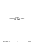
SR-1 PARTS LAYOUT DIAGRAM
SR-1 – 7
PARTS LIST
CAPACITORS
3 100 pf disc capacitors (marked 100, 101, or 100K) (C3,7,8)
11 .01µF disc capacitors (marked .01, 103, or 10nF)
(C1,2,5,9,10,11,12,13,14,15,18)
3 4.7µF to 10µF electrolytic capacitors (C6,17,22)
3 100 to 220µF electrolytic capacitors (C16,20,21)
1 .1µF ceramic disc capacitor (marked .1 or 104) (C19)
1 10 pF ceramic disc capacitor (marked 10)(C23)
INDUCTORS
2 Shielded coils (marked 5015-015) (L1,L2)
2 1800 µH inductors (marked 182J)(L3)
RESISTORS
1 2 ohm [red-black-gold] (R16)
1 270 ohm [red-violet-brown] (R5)
2 1K ohm [brown-black-red] (R6,R9)
3 10K ohm [brown-black-orange] (R4,R10,R11)
3 47K ohm [yellow-violet-orange] (R7,R8,R15)
2 100K ohm [brown-black-yellow] (R12,R13)
1 1M ohm [brown-black-green] (R14)
SEMICONDUCTORS
1 1N270 diode, glass bead style (D2)
1 Varactor diode, transistor style body with two leads (MVAM108) (D1)
4 NPN transistors, 2N3904 or similar (Q1,2,3,4)
1 NE602 8-pin DIP IC (U1)
1 LM358 8-pin DIP IC (U2)
1 LM386 8-pin DIP IC (U3)
HARDWARE AND MISCELLANEOUS
1 SR-1 printed circuit board
3 10K potentiometers (R1,2,3)
1 DPDT PC-mount push button switch (S1)
1 RCA-type PC-mount jack (J1)
1 Subminiature phone jack (J2)
1 9-volt battery snap connector
1 9-volt battery hold-down clamp
REQUIRED, NOT SUPPLIED:
9-volt alkaline or heavy-duty battery
Earphone, small speaker, or external amplifier with speaker
Antenna or suitable cable, connector, grounding
OPTIONAL
SR-1 – 8
ASSEMBLY INSTRUCTIONS
In ALL PC-board assembly steps, our word "INSTALL" means to do this:
Insert the part, oriented or "pointed" correctly, into its holes in the PC
board.
If helpful, gently BEND the part's wire leads or tabs to hold it in place,
with the body of the part snugly against the top side ("component side")
of the circuit board.
Solder ALL wires or pins of the part.
Trim or "nip" all excess wire lengths extending beyond each solder
connection, taking care that wire trimmings do not become lodged in
solder connections.
You can see that this circuit board, the center portion in particular, is fairly
well-filled with components. There's more to this receiver than the average
beginner's radio or even our popular Amateur Band receivers.
Follow the assembly instructions IN SEQUENCE and check off each step as
understood and completed. Some of the components require modification!
Examine the schematic circuit diagram and PC Board parts layout diagram
as you proceed.
Use good soldering techniques! Let your soldering iron tip heat both the
component lead wire and PC board trace enough so that the wire itself AND
the foil trace BOTH become hot enough TOGETHER to melt a bit of solder
so that it flows smoothly from the pin to the PC board trace.
Enough said... Let’s get building!
1. Install J1, the RCA antenna jack. Solder all 4 points.
2. Install S1, the DC on-off switch. It fits only one way. Ensure that the
white plastic switch extends out over the edge of the printed circuit
board.
3. Install C1, a .01 µF (marked .01 or 103) signal coupling capacitor,
which brings the antenna signal up to the front of the PC board. Notice
the long PC trace from J1 through C1 to R1.
4. Install potentiometer R1, the RF gain control.
5. Now, it's time for a little "destruction"! (If you jumped ahead and
installed L1 and L2, we've got bad news for you). Before these two
SR-1 – 9
shielded transformers can be installed, their internal capacitors need to
be removed. Looking at the underside of these two transformers, you'll
see a tubular part, probably white with a brown band, somewhat like the
resistors in this kit. These are brittle and easily crushed with any sharp
object that can be pressed against them with mild force(small nail,
nutpick, small screwdriver). You'll find these capacitors will easily
disintegrate into particles. DO NOT do anything to the larger dual IF
transformer, L3.
6. Install L1, which peaks or preselects the signal input from the antenna
through C1 and R1.
7. Install U1, the NE602 IC mixer oscillator. The marked end of the IC
(band or dot) must face the FRONT of the PC board (the end with the
switch and dials.) If you wish, install an 8- pin DIP socket, still
remembering to orient and install correctly. Please don't be afraid to
solder U1 directly to the PC board, as we have seen more repair
problems associated with DIP sockets than from direct soldering of IC
chips!
8. Install C2, .01 µF (marked .01 or 103). C2 will bypass pin 2 of the
NE602 to ground. The antenna signal coupled through C1, level
controlled by R1, peaked by L1 is now fed to input pins 1 and 2 of the
NE602. Pin 3 of the NE602 is now connected to ground, as required.
9. Install C16, a large 100 or 220 µF electrolytic. The positive side must
face towards the NE602. (Note: The prominent stripe on the side of the
capacitor usually designates the negative side, not the positive side).
10. Install Q4, NPN 2N3904 next to C16. Note the orientation of the flat
side.
11. Install C3, 100 pF (marked 100 or 101), which goes across pins 6
and 7 of the NE602 IC. This capacitor is a first step in setting up the
resonant frequency of the NE602's internal oscillator, using the resonant
LC circuit to be created along with C4,L2 and the varactor tuning circuit.
12. Install C4, 100 pF (marked 100, 101 or 100K).
13. Install C5, .01 µF (marked .01 or 103).
14. Install Jumper Wire, JMP1, using a scrap of bare wire trimmed from
a previously-installed part. This jumper is an "overpass" which brings +9
volts to the NE602 and varactor tuning.
15. Near to Jumper 1, install R4, 10K [brown-black-orange].
16. Before L2 may be installed, its internal capacitor must be removed by
crushing it with a small screwdriver or knife blade, just as for L1. Omitting
this step will prevent the oscillator from tuning the intended frequency
SR-1 – 10
range.
17. Install L2, the oscillator coil.
18. Install D1, the varactor diode, which looks just like a transistor but
with only two leads, making sure that the flat side is oriented correctly.
19. Install R5, 270 ohm (red-purple-brown)
20. Install R2, 10K potentiometer tuning control.
21. Install C6, 10 µF. electrolytic below R2.
22. Install R3, 10K potentiometer volume control.
23. Install C9, .01 µF (marked .01, 103 or 10nF).
PROGRESS SUMMARY
In addition to becoming familiar with the PC board and installing a
respectable number of parts, you've made TWO accomplishments worth
noting. First, you have modified L1 and L2 as needed. Second, if you'll peek
at the left "third" of the schematic diagram, following from the antenna to C7,
you already have built a "direct conversion" shortwave receiver capable of
CW-SSB reception throughout the SR-1's tuning range. If you want to prove
it to yourself, connect an antenna, 9 volts DC to Jumper 1, and a high-gain
test amplifier to C7. You will hear plenty of CWInductor leads go here
RTTY shortwave signals as well as the "carrier"
signals of the AM broadcast signals which this
SR-1 superhet receiver is designed to detect
and amplify. .
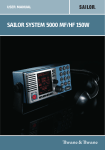
24 Locate the two green 1800 µH
inductors (marked 182J). These inductors
will be placed in the position marked for L3.
Follow the diagram at right for proper
placement of the inductors.
Inductor leads go here
10 pF capacitor on back of board
10
25. Flip the circuit board over
and install a 10 pF capacitor on
the bottom side of the board
between the two inductors
installed in step 24. (see below for
placement)
SR-1 – 11
26. Install C15, .01 µF (marked .01, 103 or 10nF).
27. Install C7 and C8, both 100 pF (marked 100, 101 or 100K).
28. All four transistors used in the SR-1 are identical NPN type 2N3904
or similar. Transistors are installed just like any other part - don't be
afraid to use enough heat to make good, clean connections. When
installing transistors, gently work their three leads to slide into the three
holes at the same time, don't try to pre-form the wires. Press firmly
without jamming too hard.
29. Install NPN transistor Q1 per step #29.
30. Install NPN transistor Q2 per step #29.
31. Install C11, .01µF (marked .01, 103 or 10nF).
32. Install R7, 47K [yellow-purple-orange].
33. Install R6, 1K [brown-black-red].
34. Install C10, .01 µF (marked .01, 103 or 10nF).
35. Install R8, 47K [yellow-purple-orange].
36. Install R9, 1K [brown-black-red].
37. Install C12, .01 µF (marked .01, 103 or 10nF).
38. Referring to Step 29, install NPN transistor Q3.
39. Install 1N270 glass bead diode D2. The banded end (cathode)
MUST be oriented as shown on parts layout.
40. Install C13, .01 µF (marked .01, 103 or 10nF).
41. Install R11, 10K [brown-black-orange].
42. Install R13, 100K ohms [brown-black-yellow].
43. Install R12, 100K ohms [brown-black-yellow].
44. Install R14, 1 megohm [brown-black-green].
45. Refer, if necessary, to Step 7 regarding the NE602 IC already
installed. Install U2, the LM358 IC, making very sure that its notched end
is toward the front of the PC board.
46. Install C14, .01 µF (marked .01, 103 or 10nF).
47. Install Jumper Wire, JMP2.
48. Install R10, 10K [brown-black-orange].
49. Install R15, 47K [yellow-purple-orange].
SR-1 – 12
50. Install R16, 2 ohm [red-black-gold].
PROGRESS SUMMARY
Your shortwave broadcast receiver is now finished, except for using just a
few more parts to build a very effective speaker amplifier circuit.
51. Near R3 (volume control), install C17, 10 µF. electrolytic. This and
most remaining capacitors are polarized electrolytics, so please watch
your (+) and (-) designations and part orientations!
52. Install C18, .01 µF (marked .01, 103 or 10nF).
53. Install U3, the LM386 audio amplifier IC chip. The notched or banded
end MUST face to the right (battery area).
54. Install C19, .1 µF (marked .1 or 104).
55. Install C20, 100 to 220 µF. electrolytic.
56. Install C21, 100 to 220 µF. electrolytic.
57. Install J2, the subminiature speaker-headphone jack.
58. Install the 9-volt battery snap connector, making sure that the red (+)
59. If you desire increased audio output, C22, 10 µF, may be installed.
and black (-) leads are inserted correctly.
60. Install the battery clamp. Position battery and holder so as not to
cover nearby PC board mounting holes. Use the method for securing the
clamp that is most convenient for you, such as:
•
•
•
•
wire looped through clamp and PC board holes, soldered.
small screws
double-faced adhesive strips
hot-melt glue
SHORTWAVE ANTENNA IDEAS
The type of antenna you'll want to use for your SR-1 depends on the degree
of interest you have in shortwave listening, on whether you are limited to an
indoor or balcony antenna, and on whether you think you may soon want to
obtain a ham radio license. If the latter is true, you may want to consult ham
radio literature and build the dipole or vertical antenna which you also plan to
use for ham listening and transmitting. A 40-meter (7 Mhz) antenna is quite
nice for the tuning range of the SR-1.
The rest of these notes on antennas are for the benefit of SR-1 builders who
simply wish to enjoy some shortwave broadcast listening. The SR-1 is very
SR-1 – 13
sensitive, so its antenna requirements are minimal for casual evening
listening when international broadcast signals are quite strong. 10 to 20 feet
of insulated hookup wire can be neatly strung behind furniture and curtains
for an adequate indoor antenna. The same length of wire, or more, outdoors
or up in the attic, will be an even better receiving antenna.
•
1. The ideal antenna setup for this frequency range is considered to be
an outdoor wire 25 to 50 feet in length, with the ground side of the
antenna jack connected to a copper cold water pipe.
•
2. For convenience, a short length of audio cable with pre-wired RCA
plug is adequate for making antenna and ground connections. (RF
coaxial cable is not essential for this application).
•
3. A "banana plug" may also be plugged into the antenna jack but will
not provide a ground connection.
•
4. If an indoor antenna is necessary, simply make it as long as possible
and as high up from concrete floors as you can.
•
5. When installing any outdoor antenna, BE VERY CAREFUL not to let
your antenna wire come in contact with electric power lines.
•
6. Any antenna wire for shortwave listening may run horizontally,
vertically or some both ways, or at an angle!
•
7. If you have a roof-mounted TV antenna, its feedline will make a great
antenna for your SR-1.
•
8. Some existing objects such as; metal downspouts, gutters, windows,
door screens, or attic insulation foil can serve as antennas!
If you are completely restricted to indoor antennas, you will enjoy the extra
boost of the Ramsey Active Antenna Kit, model AA-7. It's built-in whip
antenna can also be boosted by your simple indoor wire antenna, and the
AA-7 may be used with any receiver or even a VHF scanner. It's easy to
build and a nice companion for your SR-1. If you need more construction
details on antennas, check the book mentioned on page 6, or any
introductory ham radio book, or the Radio Shack book on Antennas (No. 621083).
SR-1 – 14
INITIAL TESTING AND ADJUSTMENT
Before turning on your receiver, please double-check the following:
correct orientation of all three IC's.
correct orientation of flat side of all four transistors.
correct orientation of the two diodes.
correct polarity of all electrolytic capacitors.
1. Connect a speaker or earphones and antenna.
2. Install a fresh 9-volt alkaline battery.
3. Set all three potentiometer controls to their middle positions.
4. Turn ON the receiver.
After adjusting the volume to a pleasant level, you should hear some
shortwave stations by turning the Tune control, no matter how any of the
adjustable coils happen to be set. Turn the RF Gain control to make sure it is
working and then set it at the lowest level needed for good reception.
While listening to any kind of station, whether broadcast or Teletype, etc.,
use a small screwdriver to adjust both slugs in the dual transformer for the
best-sounding reception. The black slug will be almost to the top of its range
(fully counterclockwise). The blue slug will give peak reception about two
turns clockwise down from its highest position.
The Tuning Control covers any 2.5 Mhz. segment selected by adjustment of
oscillator coil L2. Both L1 and L2 must be adjusted with a non-metallic
alignment tool such as is used in radio-TV service. If you do not have one, a
suitable tool can be made by patiently sanding a screwdriver-like blade on
the end of a wooden match stick, kabob skewer or small plastic crochet
needle. Again, please be aware that a metal screwdriver blade will drastically
increase the coil inductance and make adjustment quite difficult. L1 is simply
adjusted for strongest reception of any signal range that is tuned in.
If you are without any kind of testing or frequency reference equipment
whatsoever, the easiest way to start enjoying your SR-1 is, with the Tune
control set at its midpoint, to slowly tune L2 with your alignment tool as
though it were a tuning dial. Stop when you come into the middle of a group
or cluster of foreign broadcast stations. Try tuning around these stations with
the Tune control. If you like what you hear, readjust both L1 and L3 for best
reception. Eventually, you will get a clue as to what general frequency band
you are hearing, because many stations periodically announce their
frequencies, particularly at sign-on and sign-off times.
SR-1 – 15
If you like precision, use a frequency counter or calibrated receiver to find the
SR-1's strong oscillator signal, remembering that there is a 260 Khz IF
difference between the local oscillator frequency and the broadcast signal
you are hearing.
Following are results of tests on an SR-1 to give you a general guideline on
what to expect if you want to pre-set adjustments of oscillator coil L2. Each
turn of L2 is one full turn clockwise. Please realize the margin of error from
receiver to receiver in such measurements, due to the manufacturing
tolerances of the capacitors and coils involved. Also, notice how the amount
of frequency change per turn increases with each turn. However, we can see
that a setting of somewhere between 4 and 5 turns might permit tuning of all
three of the major shortwave bands under 10 Megahertz, depending on the
characteristics of your particular varactor diode. A 2.5 Mhz. swing is all that
we can reasonably guarantee.
L2 SETTING
OSCILLATOR RANGE
TUNING RANGE
Flush at top of shield
3.94-6.77 Mhz
3.68-7.03 Mhz
1 turn
4.01-6.87 Mhz
3.75-7.13 Mhz
2 turns
4.27-7.31 Mhz
4.01-7.57 Mhz
3 turns
4.77-8.20 Mhz
4.51-8.46 Mhz
4 turns
5.50-9.30 Mhz
5.24-9.56 Mhz
5 turns
6.31-9.83 Mhz
6.05-10.09 Mhz
6 turns
7.10-10.20 Mhz
6.84-10.46 Mhz
Maximum
7.27-10.25 Mhz
7.01-10.51 Mhz
SR-1 – 16
TROUBLESHOOTING TIPS
If you experience difficulty, think of your SR-1 in its several sections or
stages: oscillator-mixer (NE602), IF audio and AGC, and final audio output
(LM386). The first step in case of problems is to make sure that the tunable
oscillator is working, which can be done by listening for its signal on another
receiver. After the oscillator circuit is confirmed working, standard signal
tracing procedures should isolate any problem, which will be either an
incorrectly-installed part, a defective part or a bad solder connection. Correct
orientation or polarity of all diodes, transistors, electrolytic capacitors and ICs
is essential.
PROBLEM: Self-oscillation or motorboating
SOLUTION: Be certain that C6 is a 4.7 to 10 µF. electrolytic and that R12 is
100K. A minor tendency toward oscillation may be noted when the Tuning
control is in an extreme position of its rotation, but this need not be a
problem if L2 is adjusted so that desired stations fall in the main rotation
range.
PROBLEM: Strong shortwave broadcast audible throughout tuning range
SOLUTION: This can occur if your antenna is "too good" or if the RF Gain
control is turned up too high. The high sensitivity of the NE602 front end is
designed for simple antennas, with most reception quite satisfactory with the
RF gain at its midpoint or so.
PROBLEM: Local AM radio station audible throughout tuning range
SOLUTION: Whether this will even happen depends on how close you are to
a local AM station. It is very important that all component leads be as short
as possible, since just a bit of wire can help D2 and the several stages of
audio amplification give you a free, unwanted "classic crystal radio". A
grounded metal case for the SR-1 is one possible solution. Another fix is to
solder a .001 µF capacitor in parallel with R10, so that it bypasses the anode
of D2 to ground. In theory, this would bypass ALL signals to ground, but this
solution has proven effective in two SR-1s constructed by the author.
PROBLEM: Unstable, chirpy signals at higher speaker levels
SOLUTION: Even in AM mode, signal "chirp" is distinguishable and is a sign
that current requirements of the IF and and audio stages are swinging the
voltage to the NE602 oscillator and varactor tuning. The receiver draws
about 200 mA. at peak audio volume, which means that a good fresh
alkaline battery is essential. If this poses a serious problem for pleasant
listening and your battery budget, consider an external battery supply (D
cells), AC power supply, or running the oscillator from its own 9-volt battery
as explained in the section for hams and experimenters. For casual listening
at moderate speaker volume, or earphone listening, the single 9-volt alkaline
SR-1 – 17
battery will give very satisfactory service.
THE RAMSEY ELECTRONICS CASE, KNOB & HARDWARE OPTION
Your finished receiver can be installed in a variety of enclosures of your own
design and choosing. You might be planning to combine several Ramsey
circuit kit boards in a single enclosure. Use of the inexpensive and attractive
Ramsey case and knob kit will give your unit that finished look and increase its
resale value. These sturdy black instrument cases are supplied with neatly
lettered front and rear panels, knobs, rubber feet and mounting screws.
OTHER ENCLOSURE RECOMMENDATIONS
While we believe that the Ramsey enclosure and knob option is a fine value
for finishing off your Ramsey receiver or transmitter, we are happy to give you
a couple of additional suggestions and our reasons for them. If your first goal
is economy and rugged portability, you will find that the circuit board can be
mounted nicely in a standard VHS videotape storage box, which also gives
room for a speaker, or earphone storage, and even a roll of antenna wire. The
controls are easily mounted at one end of such a box. It may be necessary to
cut away the molded posts which secure the tape cassette itself. These
storage boxes come in several styles, so pick one which looks truly practical
as a project enclosure.
To accomplish RF shielding, the most economical metal enclosure nicely
suited for Ramsey kit boards is Radio Shack No. 270-253A. This metal utility
cabinet can accommodate both a receiver and our AA-7 Active Antenna, plus
speaker, with room for various refinements you might like to add, such as
power supply or larger battery pack, etc.
SR-1 – 18
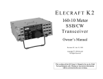
A TUNING DIAL?
If you use your own enclosure and knobs, you will probably plan some sort of
dial markings. If you finish your receiver with the Ramsey custom case and
knob kit, you may wish to copy one of the following designs to make a logging
scale:
SR-1 – 19
Notes:
SR-1 – 20
The Ramsey Kit Warranty
Please read carefully BEFORE calling or writing in about your kit. Most problems can be solved
without contacting the factory.
Notice that this is not a "fine print" warranty. We want you to understand your rights and ours too! All
Ramsey kits will work if assembled properly. The very fact that your kit includes this new manual is
your assurance that a team of knowledgeable people have field-tested several "copies" of this kit
straight from the Ramsey Inventory. If you need help, please read through your manual carefully, all
information required to properly build and test your kit is contained within the pages!
1. DEFECTIVE PARTS: It's always easy to blame a part for a problem in your kit, Before you conclude
that a part may be bad, thoroughly check your work. Today's semiconductors and passive components
have reached incredibly high reliability levels, and it’s sad to say that our human construction skills
have not! But on rare occasions a sour component can slip through. All our kit parts carry the Ramsey
Electronics Warranty that they are free from defects for a full ninety (90) days from the date of
purchase. Defective parts will be replaced promptly at our expense. If you suspect any part to be
defective, please mail it to our factory for testing and replacement. Please send only the defective part
(s), not the entire kit. The part(s) MUST be returned to us in suitable condition for testing. Please be
aware that testing can usually determine if the part was truly defective or damaged by assembly or
usage. Don't be afraid of telling us that you 'blew-it', we're all human and in most cases, replacement
parts are very reasonably priced.
2. MISSING PARTS: Before assuming a part value is incorrect, check the parts listing carefully to see
if it is a critical value such as a specific coil or IC, or whether a RANGE of values is suitable (such as
"100 to 500 uF"). Often times, common sense will solve a mysterious missing part problem. If you're
missing five 10K ohm resistors and received five extra 1K resistors, you can pretty much be assured
that the '1K ohm' resistors are actually the 'missing' 10 K parts ("Hum-m-m, I guess the 'red' band really
does look orange!") Ramsey Electronics project kits are packed with pride in the USA. If you believe
we packed an incorrect part or omitted a part clearly indicated in your assembly manual as supplied
with the basic kit by Ramsey, please write or call us with information on the part you need and proof of
kit purchase
3. FACTORY REPAIR OF ASSEMBLED KITS:
To qualify for Ramsey Electronics factory repair, kits MUST:
1. NOT be assembled with acid core solder or flux.
2. NOT be modified in any manner.
3. BE returned in fully-assembled form, not partially assembled.
4. BE accompanied by the proper repair fee. No repair will be undertaken until we have received the
MINIMUM repair fee (1/2 hour labor) of $18.00, or authorization to charge it to your credit card
account.
5. INCLUDE a description of the problem and legible return address. DO NOT send a separate letter;
include all correspondence with the unit. Please do not include your own hardware such as
non-Ramsey cabinets, knobs, cables, external battery packs and the like. Ramsey
Electronics, Inc., reserves the right to refuse repair on ANY item in which we find excessive
problems or damage due to construction methods. To assist customers in such situations,
Ramsey Electronics, Inc., reserves the right to solve their needs on a case-by-case basis.
The repair is $36.00 per hour, regardless of the cost of the kit. Please understand that our technicians
are not volunteers and that set-up, testing, diagnosis, repair and repacking and paperwork can take
nearly an hour of paid employee time on even a simple kit. Of course, if we find that a part was
defective in manufacture, there will be no charge to repair your kit (But please realize that our
technicians know the difference between a defective part and parts burned out or damaged through
improper use or assembly).
4. REFUNDS: You are given ten (10) days to examine our products. If you are not satisfied, you may
return your unassembled kit with all the parts and instructions and proof of purchase to the factory for a
full refund. The return package should be packed securely. Insurance is recommended. Please do not
cause needless delays, read all information carefully.
SR-1 – 21
SR-1 Shortwave Receiver
Quick Reference Page Guide
Introduction to the SR-1 ...................... 4
What You Can Expect to Hear ............ 4
Shortwave Listening as a Hobby......... 5
Circuit Description ............................... 6
Parts Layout Diagram ......................... 7
Parts List ............................................. 8
Assembly Instructions ......................... 9
Schematic Diagram............................. 12
Shortwave Antenna Ideas ................... 15
Initial Testing and Adjustment ............ 17
Troubleshooting Tips .......................... 19
Case, Knob and Dial Information ........ 20
Ramsey Kit Warranty .......................... 23
REQUIRED TOOLS
• Soldering Iron (Radio Shack #RS64-2072)
• Thin Rosin Core Solder (RS64-025)
• Needle Nose Pliers (RS64-1844)
• Small Diagonal Cutters (RS64-1845)
• <OR> Complete Soldering Tool Set
(RS64-2801)
TOTAL SOLDER POINTS
166
ESTIMATED ASSEMBLY
TIME
Beginner .............. 5.0 hrs
Intermediate ........ 3.0 hrs
Advanced ............. 2.0 hrs
ADDITIONAL SUGGESTED ITEMS
• Soldering Iron Holder/Cleaner (RS64-2078)
Manual Price Only: $5.00
Ramsey Publication No. MSR-1
Assembly and Instruction manual for:
RAMSEY MODEL NO. SR-1
SHORTWAVE RADIO KIT
Printed on
Recycled Paper
RAMSEY ELECTRONICS, INC.
793 Canning Parkway
Victor, New York 14564
Phone
(716) 924-4560
Fax
(716) 924-4555
SR-1 – 22