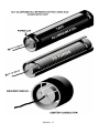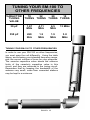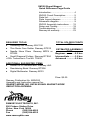
1
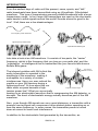
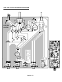
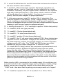
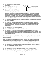
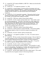
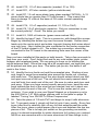
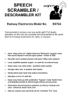
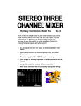
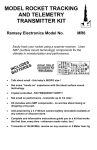
NOISE REDUCTION ANTENNA Ramsey Electronics Model No. SM100 Trying to receive distant stations “down in the noise” ?!! Frustrated by continuous powerline noise or adjacent channel interference ? Try our signal “magnet” to pull in those weak stations. • Tunes entire AM broadcast band and can also be configured for any frequency range between 500 KHz to 15 MHz ! • Stuck for space ? Out performs “long wire” short wave radio antennas 100 times it size ! • Features a Faraday shield to eliminate electrostatic noise caused by powerlines, florescent lamps, or light dimmers - completely static free reception. • Varactor diode tuning ensures precise station tuning - really helps to pull in those weak stations. • Directional properties of the antenna help to “null” overpowering local stations in order to get that rare station. • Low noise, high gain FET preamplifier circuit is housed inside the antenna assembly, where it’s needed most ! • Rugged antenna enclosure constructed from PVC pipe “weatherproofs” the ferrite rod antenna assembly, making the antenna ideal for use indoors or out. • E - Z one wire connection from the tuner box to antenna assembly, can be run up to 500’ ! • Complete and informative instructions guide you to a kit that works the first time, every time - enhances resale value, too ! SM100 • 1 RAMSEY TRANSMITTER KITS • FM100B Professional FM Stereo Transmitter • FM25B Synthesized Stereo FM Transmitter • MR6 Model Rocket Tracking Transmitter • TV6 Television Transmitter RAMSEY RECEIVER KITS • FR1 FM Broadcast Receiver • AR1 Aircraft Band Receiver • SR2 Shortwave Receiver • SC1 Shortwave Converter RAMSEY HOBBY KITS • SG7 Personal Speed Radar • SS70A Speech Scrambler • BS1 “Bullshooter” Digital Voice Storage Unit • AVS10 Automatic Sequential Video Switcher • WCT20 Cable Wizard Cable Tracer • LC1 Inductance-Capacitance Meter • TFM3 Tri-Field Meter • SHA1 Stereo Headphone Amplifier • ECG1 Heart Monitor RAMSEY AMATEUR RADIO KITS • DDF1 Doppler Direction Finder • HR Series HF All Mode Receivers • QRP Series HF CW Transmitters • CW7 CW Keyer • CPO3 Code Practice Oscillator • QRP Power Amplifiers RAMSEY MINI-KITS Many other kits are available for hobby, school, Scouts and just plain FUN. New kits are always under development. Write or call for our free Ramsey catalog. SIGNAL MAGNET NOISE REDUCTION ANTENNA KIT INSTRUCTION MANUAL Ramsey Electronics publication No. MSM100 Revision 1.1a First printing: June, 1994 Second printing: September, 1994 COPYRIGHT 1994 by Ramsey Electronics, Inc. 590 Fishers Station Drive, Victor, New York 14564. All rights reserved. No portion of this publication may be copied or duplicated without the written permission of Ramsey Electronics, Inc. Printed in the United States of America. SM100 • 2 Ramsey Publication No. MSM100 Price $5.00 KIT ASSEMBLY AND INSTRUCTION MANUAL FOR SIGNAL MAGNET NOISE REDUCTION ACTIVE ANTENNA TABLE OF CONTENTS Introduction ................................... 4 SM100 Circuit Description ............ 5 Parts list ........................................ 6 Parts Layout diagram .................... 8 Schematic diagram ....................... 9 SM100 Assembly instructions ..... 12 Setup and Testing ........................ 19 Troubleshooting ........................... 20 Ramsey kit warranty .................... 23 RAMSEY ELECTRONICS, INC. 590 Fishers Station Drive Victor, New York 14564 Phone (585) 924-4560 Fax (585) 924-4555 www.ramseykits.com SM100 • 3 INTRODUCTION From the earliest days of radio until the present, news, sports, and “talk” radio broadcasts have been transmitted using an (A)mplitude (M)odulated waveform. This type of transmission ensured reliable broadcasts with a large transmission range. In fact, large AM transmitters are used on the shortwave radio bands to send signals around the world! Sounds almost to good to be true? Well, there are a few disadvantages. Low Frequency Audio Waveform High Frequency Radio Carrier Amplitude Modulated Signal Lets take a look at an AM waveform. It consists of two parts, the “carrier” frequency, which is the frequency that you tune on your radio dial, and the “modulation,” or intelligence that is transmitted like your favorite talk show or Buffalo Bills game. noise "spikes" encoded in waveform The inherent problem with AM is that this audio information is encoded in the amplitude of the waveform, making it susceptible to a variety of outside interferences. Have you ever noticed the crackle on your AM receiver during a lightening storm? Or how about the car Amplitude Modulated Signal radio when we pass beneath a high tension power line? What you are actually hearing is an electrostatic waveform that is overpowering the AM detector, or decoder. The burst of electrostatic energy actually becomes part of the AM waveform. Also, even though AM signals can carry great distances, a transmitter with a powerful carrier signal can overpower a more distant station operating on or near the same frequency. In some cases, the transmitter power is turned down at sunset to avoid such interference. In addition to the electrostatic field generated by the transmitter, an SM100 • 4 electromagnetic waveform is also produced. This waveform is not susceptible to the ravages of electrostatic bursts so it is more desirable to receive. Well, this is exactly the problem we encountered here at Ramsey. While trying to “keep an ear on” the football sports broadcasts 90 miles away, power line noise and low power conditions caused us to string a long wire antenna in hopes of receiving a stronger signal. This worked somewhat, but didn’t really satisfy our “rigid” requirements for noise free reception. So we experimented with an active antenna design, and viola, our signal magnet was created! SM100 CIRCUIT DESCRIPTION Our signal magnet antenna consists of two parts, the antenna section (SM100A), and the control box (SM100C). Have a look at the schematic diagram and follow along. We were presented with an interesting problem when initially designing the signal magnet. We needed to run DC power, a variable control voltage, and the RF signal onto a single wire. The power and RF seemed simple enough, with a DC blocking capacitor at the antenna and the controller, but how do we also add the variable voltage? The solution, a zener diode! This can “regulate” the DC voltage at the antenna to the necessary supply voltage to run the RF preamplifier. The only drawback with this idea is that the DC supply must start at 12 VDC and tune up to 27 VDC. The control assembly consists of the voltage sources necessary to run the unit. Diodes D1 and D2 along with capacitors C1 and C4 comprise a voltage doubler that provides the unregulated 30 Volt DC supply. Zener diode D3 provides the regulation for the high (27V) DC voltage supply. The “tune” knob varies the voltage from 12 VDC to 27 VDC while transistor Q1 “buffers” the output voltage to avoid any changing on the output, as this would interfere with the tuning of the unit. Jacks J1, J2, and J4 route the RF input to your radio. The antenna assembly consists of a similar voltage regulator circuit using diode D7 to supply the 12 VDC for the RF amplifier. Transistors Q4 and Q5 are the low noise amplifier section of the circuit. Varactor diode D6 is the tunable component in the circuit whose internal capacitance changes proportionally to the reverse bias voltage applied to it. The final bit of magic is the “Faraday” shielded ferrite stick antenna. The shield effectively eliminates any electrostatic interference present. This is the input to the entire circuit and will be mounted in the weatherproof PVC pipe. We’ll discuss this in more detail later when we’re assembling this section of the circuit. SM100 • 5 SM100 PARTS LIST RESISTORS 1 1 3 5 1 1 2 1 1 1 10 ohm [brown-black-black] (R1) 75 ohm resistor [violet-green-black] (R14) 470 ohm [yellow-violet-brown] (R5, 11, 15) 1K ohm [brown-black-red] (R2, 3, 4, 7, 13) 8.2K ohm [grey-red-red] (R8) 10K ohm [brown-black-orange] (R 9) 100K ohm resistors [brown-black-yellow] (R10, 12) 1 megohm resistor [brown-black-green] (R16) 5K ohm trimmer potentiometer [marked 502M] (R17) 10K ohm PC mount potentiometer (R6) CAPACITORS 5 4 3 2 .01 uF disc capacitor [marked .01 or 103 or 10nF] (C3, 7, 12, 13, 14) .1 uF disc capacitor [marked .1 or 104] (C2, 6, 10, 11) 10 uF electrolytic capacitors (C5, 8, 9) 220 uF electrolytic capacitors (C1, 4) INDUCTORS 2 1800 uH inductors [green case marked 182] (L1, 2) SEMICONDUCTORS AND INTEGRATED CIRCUITS 1N4148 diodes [glass case with black band] (D5) 1N4002 diode [epoxy case marked 1N4002] (D1, 2) 12 volt zener diode [grey glass case marked 1N759A] (D7) 27 volt zener diode [red glass case marked 971B] (D3) Varactor diode [looks like a transistor with only two leads marked MVAM108] (D6) 1 Light Emitting Diode [LED] (D4) 4 NPN small signal transistor [marked 2N3904] (Q1, 2, 3, 4) 1 FET [marked 2N5485 or MPF102] (Q5) 1 2 1 1 1 MISCELLANEOUS PARTS AND HARDWARE 1 3 1 1 1 1 Sub-miniature power jack (J3) RCA type PC mount jacks (J1, 2, 4) DPDT pushbutton switch (S1) SM100A / SM100C printed circuit board 7.5 inch ferrite rod 11 feet of enameled magnet wire SM100 • 6 1 1 2 1 1 1 1 1 1 1 9 inch length of RG-174 mini coaxial cable 1/2 inch chassis mount “F” connector, with nut and ground lug 7 inch lengths of 1 inch diameter PVC pipe. 1 inch PVC elbow 1 inch PVC endcap with a .375 inch hole drilled in the center 1 inch PVC endcap with no hole drilled 8 inch length of 1/2 inch PVC pipe 12VAC @ 250 mA (or greater) plug in type wall transformer 3 inch length of #24 wire Paperclip RAMSEY Learn-As-You-Build KIT ASSEMBLY There are numerous solder connections on the SM100 printed circuit board. Therefore, PLEASE take us seriously when we say that good soldering is essential to the proper operation of your antenna! • • • • Use a 25-watt soldering pencil with a clean, sharp tip. Use only rosin-core solder intended for electronics use. Use bright lighting, a magnifying lamp or bench-style magnifier may be helpful. Do your work in stages, taking breaks to check your work. Carefully brush away wire cuttings so they don't lodge between solder connections. We have a two-fold "strategy" for the order of the following kit assembly steps. First, we install parts in physical relationship to each other, so there's minimal chance of inserting wires into wrong holes. Second, whenever possible, we install in an order that fits our "Learn-As-You Build" Kit building philosophy. This entails describing the circuit that you are building, instead of just blindly installing components. We hope that this will not only make assembly easier, but help you to understand the circuit you’re constructing. For each part, our word "Install" always means these steps: 1. Pick the correct part value to start with. 2. Insert it into the correct PC board location. 3. Orient it correctly, follow the PC board drawing and the written directions for all parts - especially when there's a right way and a wrong way to solder it in. (Diode bands, electrolytic capacitor polarity, transistor shapes, dotted or notched ends of IC's, and so forth.) 4. Solder all connections unless directed otherwise. Use enough heat and solder flow for clean, shiny, completed connections. SM100 • 7 SM100 • 8 SM-100 PARTS FINDER DIAGRAM LONG LEAD SM100 • 9 Now, let's get building! First things first. You'll notice that the two circuit boards are connected together. Before we begin building. we’ll need to separate the circuit boards by gently twisting the smaller SM100A circuit board to separate it from the larger SM100C board. You may use a small file or sandpaper and take off any sharp edges that were created when the PC board “broke”. Since you may appreciate some “warm-up” soldering practice as well as a chance to put some “landmarks” on the PC board, we’ll first install some “hardware” components. This will also help us to get acquainted with the up down, left - right orientation of the larger circuit board. Remember that the components will be mounted on the “component” side of the circuit board and soldered on the “solder” side of the circuit board. Be sure to save some of the clipped component leads to use as “jumper “ wires in the circuit. 1. Identify and install DPDT switch S1. Be sure to push the switch flush into the circuit board. Solder all six connections. 2. Install the front panel 10K trimmer pot [R6]. Once again, be sure to push the component flush to the circuit board before soldering. 3. Moving to the rear of the circuit board, install the three PC mount RCA phono jacks [J1, 2, 4]. These jacks will “snap” into place before soldering. Don’ be afraid to use enough heat to completely solder the grounding tabs as they will also provide strain relief when hooking up your completed kit. 4. Install the sub-miniature jack J3. Be sure that all three leads protrude through the circuit board before soldering. 5. Install R17 [small trimmer marked 502M]. Be sure that the screwdriver “slot” for adjustment faces towards the outside of the circuit board. That wasn’t so bad, now was it! You’ve just installed the controls and interfacing connectors of your signal magnets’ controller board. Take a minute now to check over your connections and resolder any that are less than perfect. Now we’ll get back to work on the power supply section of the circuit. Identify the two 1N4002 epoxy type diodes. Notice how one end is marked with a band. Be sure that this band is oriented as shown in the parts diagram. SM100 • 10 6. Install 1N4002 diodes D1 and D2. Notice that the bands do not face in the same direction when installed. 7. Install C1, 220 uf electrolytic capacitor. Electrolytic capacitors are polarized with a (+) and a (-) lead and must be installed in the correct orientation. Ordinarily, only the negative side is marked on the capacitor body with a dark band and the (-) sign clearly shown, while PC boards will usually show the (+) hole location. Use care to ensure proper polarity. See the parts diagram for proper placement. 8. In the same manner, install C4, another 220 uF electrolytic. Pay particular attention to the polarity! In this “voltage doubler” section of the circuit, installing an electrolytic backwards could cause it to explode! (We do not suggest that you do this if you have a heart condition, anyone sleeping in your house or expect a replacement part!) 9. Identify and install C5, 10 uF electrolytic capacitor. Watch that polarity! 10. Install R8, 8.2K ohm (grey-red-red). 11. Install R3, 1K ohm (brown-black-red). 12. Install R2, 1K ohm (brown-black-red). 13. Install R7, another 1K ohm (brown-black-red). 14. Install D3, the 27 volt zener diode (marked 971B). Zener diodes have a specific reverse “breakdown” voltage (for this diode 27 volts) at which the diode begins to conduct. We use this property to create a regulated voltage source at 27 volts. The “TUNE” pot (R6) that you previously installed will vary the output voltage from 12 volts to 27 volts. 16. Install LED D4. Being a diode, this component is polarized and must be oriented correctly. Examine the LED and notice how one lead is longer than the other. The longer of the two leads is the anode, or (+) connection. Most diodes also have a flat molded in the component body. This corresponds to the cathode or (-) side of the part.This flat should face in the direction of the band marking of the diode. Leave the diodes leads as long as possible as this component will also mount to the front panel as a power and tuning indicator. Notice how the LED is connected to the tunable supply. We could have just as easily hooked it to the regulated supply, but by using the variable voltage display, we can also change the intensity of the diode while turning the “TUNE” knob. How about that for getting your money’s worth out of a part ! 17. Install disc capacitor C3, .01 uF (marked .01 or 103 or 10nF). SM100 • 11 18. Install R4, 1K ohm (brownblack-red). LED (-) 19. Install R1, 10 ohm (brownblack-black). Leave these leads as long as possible PC Board 20. Locate and install Q1, a (+) 2N3904 transistor. Transistors have three "legs" and must be mounted correctly. Notice that the part contains a "flat" side with the writing imprinted on it. Be sure to follow the parts diagram for correct placement. To install, slide the center legs through the circuit board and push the component as close to the board as possible without "straining" the leads. Solder all three connections securely. 21. Install Q2, another 2N3904 transistor. Be sure to orient it as shown in the parts diagram. 22. From the scrap component leads you've been saving, form and install “jumper” wire JMP1 on the circuit board. Jumper wires act like electronic “bridges” that carry signals over the printed circuit traces underneath. 23. Install C2, .1 uF disc capacitor. 24. Install R5, 470 ohm (yellow-violet-brown). 25. Install L1, 1800 uH inductor (green cylinder marked 182). This component allows the DC voltages to pass through it, but it “chokes” off the high frequency radio waves and prevents them from getting into your power supply circuit. Whew! You’ve just completed the entire power supply portion of you signal magnet antenna. Next, we’ll move on to the antenna board. Before you go any further, we suggest that you look over your work. Try to identify and correct any cold soldering connections, solder bridges and incorrectly installed parts. 28. Install R16, 1M ohm resistor (brown-black-green). R16 is used to set the proper bias voltage on Q5. 29. Install C13, .01 uF capacitor (marked .01 or 103 or 10 nF). 30. Install C11, .1 uF capacitor (marked .1 or 104). C11 and C13 are used to pass the AC signal without passing DC current. SM100 • 12 31. Install Q5, FET marked 2N5485 or MPF102. Make sure that the flat side is facing C13. 32. Install C10, .1 uF capacitor (marked .1 or 104). 33. Install D6, a varactor diode. It looks just like a transistor with only two leads, and is marked MVAM108. A varactor diode acts as a voltage controlled variable capacitor. By increasing or decreasing the DC voltage into the varactor, we can tune the circuit to the desired frequency. 34. Install C8, a 10 uF electrolytic capacitor. Remember that the lead closest to the black stripe is the (-) lead. This lead should be towards the outside of the board when properly installed. 35. Install R10, 100K ohm resistor (brown-black-yellow). 36. Install R13, 1K ohm resistor (brown-black-red.) This resistor must be mounted standing up. To do this, first insert one of the leads all of the way into the hole marked with a circle on the parts layout diagram. Next, bend down the other leg and insert it into the other hole. You should bend it down so the resistor is still standing, but there is no excess wire standing above the circuit. 37. Install R12, 100K ohm resistor (brown-black-yellow). 38. Install Q4, an NPN transistor marked 2N3904. Q4 and Q5 amplify the incoming signal so there is a minimum signal loss going to the receiver. 39. Install R15, 470 ohm resistor (yellow-violet-brown). 40. Install C6, .1 uF capacitor (marked .1 or 104). C6 is also used to filter off noise. 41. Install R9, 10K ohm resistor (brown-black-orange). Be sure that it is mounted standing up like a soldier standing at attention (or our college intern student being questioned about various lunchtime desserts!). 42. Install C7, .01 uF disc capacitor (marked .01 or 103). C7 and C8 are used to keep the voltage oscillator from oscillating. 43. Install R14, 75 ohm resistor (violet-green-black). 44. Install Q3, NPN transistor marked 2N3904. This transistor is used as a 12 volt regulator. By keeping a constant 12V on the base, we know that the emitter voltage will always be 11.3V! Don’t forget to use the correct polarity. The flat side should face L2. 45. Install D5, 1N4148 diode (glass body with a black band). D5 is used to protect the circuit against current in the wrong direction. SM100 • 13 46. Install C12, .01 uF disc capacitor (marked .01 or 103). 47. Install R11, 470 ohm resistor (yellow-violet-brown). 48. Install D7, 12 volt zener diode (grey glass marked 1N759A). A 12 zener diode has no greater than 12 volts across it. This means that there is always 12 volts at the base of Q3 under normal operating conditions. 49. Install C14, .01 uF capacitor (marked .01, 103 or 10nF). 50. Install C9, 10 uF electrolytic capacitor. Did you remember to use the correct polarity? Good! We knew you would. 51. Install L2, 1800 uH inductor (green case marked 182). 52. Identify the type F jack. This is a connector, with thread like screws. Begin by installing the solder lug over the screw threads. Solder short leads onto the center point and solder lug point leaving both wires about one inch long. Next, solder the wire connected to the center connection of the PC board closest to L2. The solder lug connection, should be connected to the PC board in the remaining hole near the corner of the board. Now you have installed all the parts on both boards. Take a few moments to look over your work. Don’t forget find and fix any cold solder joints, solder bridges, and misplaced parts. We are going to move on to building the actual antenna itself. Since this may be a bit complicated, we hope that you will be patient and take your time. The better job you do, the better it will work in the future. 54. Identify the iron ferrite rod and the enameled wire. Starting at one end, begin to wrap the enameled wire around the ferrite rod, counting with each turn. The beginning of the wire should extend about one half inch past one end of the rod. The coil should be evenly spaced about one half inch from each end of the rod. Be sure to make each turn neat and snug. When you have wound exactly seventy turns, bend the wire back towards the end of the wire that you started, and cut it about one half inch past the end of the rod. This is now the center part of your antenna. If you wish to use your Signal Magnet on a frequency not in the 490 KHz to 1.67 MHz range, please refer to the table on page 18 labeled “Tuning Your SM100 To Other Frequencies.” 55. Take the piece of 1/2 inch PVC and begin to wrap it with aluminum foil. To properly wrap it, simply roll the foil onto it very neatly. Every few turns, take time to carefully trim off any foil that extends past the ends. After five turns, place a small paper clip at one end between the top two pieces of foil. This is to help you solder on the grounding connection, since it is almost impossible to solder aluminum foil (unless you contract NASA or are someone with a lot more aluminum foil than things to do). SM100 • 14 Wrap another six turns of foil and cut it. You may wish to hold down the foil with a small piece of tape at each end. 56. Using a sharp hobby knife, cut away a strip of aluminum foil the length of the 1/2 inch PVC about 2/10 of an inch wide. There must be no electrical connection across this gap. By cutting away the aluminum foil, we have retained the foils ability to block electrostatic waves, but not magnetic waves because it is not a full turn. See the diagram on page 17 for a pictorial description. 57. Wrap tape around each end to hold the foil down, and run a strip down the length of the strip. This should help make your antenna more durable. Make sure that the paperclip that you have installed is still there. 58. Using the length of coax supplied, first strip off the outer insulation. This is done most easily by carefully and lightly cutting the jacket all the way around about one half inch from the end and slipping the jacket off. Be careful not to cut any of the stranded wire inside. Using the tip of your knife, carefully unbraid the wire, and twist it all together on one side. Next, strip the insulation off of the center wire using wire strippers. Be sure not to strip it too close to the outer wire...we don’t want the braided shield touching the center connection. 59. Solder the center connection to one end of the coil. Be sure to strip the insulation off of the wire first. The easiest way that you will be able to do this is with a sharp hobby knife and a lot of patience. (Advanced hobbyists: Our Engineering Department has concluded after extensive testing, that a lighter or hobby torch not only doesn't remove the insulation easily, but you may actually be able to see the insulation turn black and bake itself securely onto the wire if you’re paying attention!) The best method is to just scrape away at it until all of the red coating is gone. 60. Now, solder the braided shield to the other stripped coil connection, and to the paperclip on the 1/2 inch PVC. If the aluminum foil is not grounded, it will pick up large amounts of static noise instead of cancelling them out. 61. Insert the antenna section into the PVC pipe with the coax cable extending out through the 90 degree elbow. 62. Connect the end of the coax cable to the connections on the antenna board marked “TO LOOP.” The center conductor should be placed in the hole closest to C11 while the braided shield should be placed in the hole closest to R16. The coax cable should be about nine inches long. SM100 • 15 63. Carefully push the antenna board into the PVC pipe until only the F type connector extends from the end. Fit the PVC pipe onto the elbow. You can now place the caps on both PVC pipes. Be sure that the one that covers the antenna board has a hole just large enough to allow the connector to pass through. 64. Connect a coaxial cable between the main board and the antenna board. The cable should have an RCA type connector on one end, and a type F adaptor on the other. It can be any length up to 500 feet. Remember to keep the polarity of the wires the same. The center conductor should terminate at the center of each connector. If you wish to hook up another external antenna for use when the signal magnet is not needed, hook it to the RCA jack labeled “EXT ANT”. 65. Run a wire from the output jack to the antenna connection on your radio. The outer connection on the jack is the ground wire. Congratulations! You have completed the Signal Magnet. Take a few minutes to look over all of your work. Look for cold solder joints, solder bridges, misplaced parts, and any construction mistakes in your antenna. SETUP AND TESTING To test your Signal Magnet antenna, you need just two things. First, you need a 12 volt AC power supply. Connect this to J3, the miniature phone jack. The center lead should be positive. Next, you need an AM radio. Depending on what you are using the kit for, this could be a short wave receiver or AM broadcast receiver. With the tuning knob fully CCW, connect a DC voltmeter across J1. Adjust R17 for 13.5V DC. This sets the antenna supply voltage. Run RG-59, or similar coax between the F-type connector on the antenna board and the RCA jack on the main board marked SM ANT. Connect another wire from the RCA jack on the main board marked OUT, to your radio. Turn on the 12V power to the SM100, and tune the AM radio to the desired frequency. When the radio is tuned to the proper frequency, slowly turn the tuning knob back and forth until the received signal is the loudest. This will give you the best possible performance, while filtering out any interference caused by other signals. Placing the antenna down low, possibly on the floor, turn it back and forth until the desired station is at its loudest level. This is because it is as far as possible from lights and other electric sources of interference. You may experiment to find the best location for it in your particular situation. SM100 • 16 SM100 • 17 TUNING YOUR SM-100 TO OTHER FREQUENCIES VARACTOR TUNING VALUE 70 32 20 10 TURNS TURNS TURNS TURNS 30 pF 1.67 MHz 4.11 MHz 6.5 MHz 13 MHz 350 pF 490 KHz 1.2 MHz 1.9 MHz 3.8 MHz TUNING YOUR SM-100 TO OTHER FREQUENCIES. In order to use your SM-100 on other frequencies, you must wrap the coil differently. Using the table above, and knowing your intended frequency range, pick the correct number of turns for your purposes. The varactor capacitive value shows the extreme limits of the varactor’s capacitive value in this circuit, and they are achieved in the tuning circuit. Remember that by keeping the bandwidth of the antenna very small, noise from unwanted stations may be kept to a minimum. SM100 • 18 Now you are all set to sit back and enjoy your Signal Magnet! We hope that you find it both useful and valuable, both as an educational tool, which you have already benefited from, and a recreational one, which you will enjoy for years. The SM100 is not intended to replace long wire antennas, although under certain conditions, it will outperform them. Please be aware that you may encounter stations that you will receive better on another antenna. For this reason, we have included a bypass jack. Also, since your antenna involves a good amount of construction by you, the hobbyist or experimenter, you should expect to get out the same quality of performance out of it as you put into it. We hope that you take your time in deciding the exact frequency range and setup that you will be using the SM100 in, so that you get the best overall performance. TROUBLESHOOTING INSTRUCTIONS While we had hoped that it wouldn’t come to this, if you are having trouble with your antenna, here are a few suggestions. By far the most common source of problems is due to misplaced parts or poor solder connections. It’s always best to take a break before searching for bad connections. Around here it’s referred to as the “Irwin Time Test” which states that “anything left alone long enough seems to repair itself !” A good way of checking component placement is to double check the assembly steps going backwards from the last steps to the first. Bright lighting and a magnifying aid can be helpful in identifying soldering problems. We’ve all made silly mistakes and never been able to see them ourselves, so have a friend check your work, as well. Use a methodical, logical troubleshooting technique. Most problems can be solved using common sense. A volt-ohm meter and a clear head are usually all that are needed to correct any problem. Please understand that it is nearly impossible to “troubleshoot” by phone, any specific questions should be documented and sent to us by mail. COMMON QUESTIONS Problem: “When I turn on the unit, the LED does not light up.” Solution: Do you have the power hooked up correctly? Disconnect everything except for the power one item at a time. If the LED comes on, it was the part that you unplugged (i.e. antenna) that is giving you problems. If you unplug everything, (except for power!) and the LED is still not lit up, SM100 • 19 suspect a construction problem on the main board and inspect it for incorrectly placed parts and bad solder joints. Problem: “The antenna doesn't pick anything up, but signals are received through the existing antenna.” Solution: You probably have an faulty wire connection, or a problem on one of the two boards. Be sure to inspect each part carefully. Using an ohmmeter, make sure that there is a DC entering the antenna board from the main board. Also, make sure that the aluminum foil antenna covering has been cut as instructed, and there are no connections across the gap. Any connections will allow the foil to act as a shield that will block out most signals. This is best checked by visual inspection, as the foil will still conduct around the other side of the PVC pipe. Problem: “There is a large amount of static in the transmission.” Solution: Did you connect the paperclip and aluminum foil to the braided wire? This should eliminate most noise. Also, you can try turning or relocating the antenna, attempting to tune it out using the tuning, or trying to identify the source of noise. Problem: “I don’t hear any signal from the SIGNAL MAGNET ANTENNA or the antenna connected to the EXISTING ANTENNA jack.” Solution: There is a bad connection between the Signal Magnet and your radio, or it is not hooked up properly. Check in this area. Also, be sure that there is a signal on that frequency. This can be accomplished by plugging in the extra antenna directly to the receiver. Problem: “I still get a bit of “powerline hum” from the Signal Magnet.” Solution: Make sure that all leads are as short as possible, and that you are using coaxial cable where indicated. Any leads longer than necessary, or runs of straight wire are great for picking up powerline hum and static noise, the very thing that we are trying to get rid of! Problem: “The SIGNAL MAGNET seems to work, but it is not acting like a directional antenna.” Solution: Check the orientation of the coax leading from the SM100A circuit board to the antenna coil. If the polarity has been switched by accident, the unit will not give you satisfactory results will in operation. SM100 • 20 Problem: “Hey, I don’t own an AM radio!” Solution: We can’t help you with that, but the Signal Magnet does work great with our HR40 40 Meter Receiver Kit! SM100 • 21 CONCLUSION We sincerely hope that you have enjoyed the construction and use of this Ramsey Kit. As always, we have tried to compose our manual in the easiest, most “user friendly” format that is possible. As our customers, we value your opinions, comments, and additions that you would like to see in future publications. Please submit comments or ideas to: Ramsey Electronics Inc. Attn. Hobby Kit Department 590 Fishers Station Drive Victor, NY 14564 or [email protected] And once again, thanks from the folks at Ramsey! SM100 • 22 The Ramsey Kit Warranty Please read carefully BEFORE calling or writing in about your kit. Most problems can be solved without contacting the factory. Notice that this is not a "fine print" warranty. We want you to understand your rights and ours too! All Ramsey kits will work if assembled properly. The very fact that your kit includes this new manual is your assurance that a team of knowledgeable people have field-tested several "copies" of this kit straight from the Ramsey Inventory. If you need help, please read through your manual carefully, all information required to properly build and test your kit is contained within the pages! 1. DEFECTIVE PARTS: It's always easy to blame a part for a problem in your kit, Before you conclude that a part may be bad, thoroughly check your work. Today's semiconductors and passive components have reached incredibly high reliability levels, and its sad to say that our human construction skills have not! But on rare occasions a sour component can slip through. All our kit parts carry the Ramsey Electronics Warranty that they are free from defects for a full ninety (90) days from the date of purchase. Defective parts will be replaced promptly at our expense. If you suspect any part to be defective, please mail it to our factory for testing and replacement. Please send only the defective part (s), not the entire kit. The part(s) MUST be returned to us in suitable condition for testing. Please be aware that testing can usually determine if the part was truly defective or damaged by assembly or usage. Don't be afraid of telling us that you 'blew-it', we're all human and in most cases, replacement parts are very reasonably priced. 2. MISSING PARTS: Before assuming a part value is incorrect, check the parts listing carefully to see if it is a critical value such as a specific coil or IC, or whether a RANGE of values is suitable (such as "100 to 500 uF"). Often times, common sense will solve a mysterious missing part problem. If you're missing five 10K ohm resistors and received five extra 1K resistors, you can pretty much be assured that the '1K ohm' resistors are actually the 'missing' 10 K parts ("Hum-m-m, I guess the 'red' band really does look orange!") Ramsey Electronics project kits are packed with pride in the USA. If you believe we packed an incorrect part or omitted a part clearly indicated in your assembly manual as supplied with the basic kit by Ramsey, please write or call us with information on the part you need and proof of kit purchase. 3. FACTORY REPAIR OF ASSEMBLED KITS: To qualify for Ramsey Electronics factory repair, kits MUST: 1. NOT be assembled with acid core solder or flux. 2. NOT be modified in any manner. 3. BE returned in fully-assembled form, not partially assembled. 4. BE accompanied by the proper repair fee. No repair will be undertaken until we have received the MINIMUM repair fee (1/2 hour labor) of $25.00, or authorization to charge it to your credit card account. 5. INCLUDE a description of the problem and legible return address. DO NOT send a separate letter; include all correspondence with the unit. Please do not include your own hardware such as nonRamsey cabinets, knobs, cables, external battery packs and the like. Ramsey Electronics, Inc., reserves the right to refuse repair on ANY item in which we find excessive problems or damage due to construction methods. To assist customers in such situations, Ramsey Electronics, Inc., reserves the right to solve their needs on a case-by-case basis. The repair is $50.00 per hour, regardless of the cost of the kit. Please understand that our technicians are not volunteers and that set-up, testing, diagnosis, repair and repacking and paperwork can take nearly an hour of paid employee time on even a simple kit. Of course, if we find that a part was defective in manufacture, there will be no charge to repair your kit (But please realize that our technicians know the difference between a defective part and parts burned out or damaged through improper use or assembly). 4. REFUNDS: You are given ten (10) days to examine our products. If you are not satisfied, you may return your unassembled kit with all the parts and instructions and proof of purchase to the factory for a full refund. The return package should be packed securely. Insurance is recommended. Please do not cause needless delays, read all information carefully. SM100 • 23 SM100 Signal Magnet Quick Reference Page Guide Introduction .................................... 4 SM100 Circuit Description ............. 5 Parts list ......................................... 6 Parts Layout diagram .................... 8 Schematic diagram ........................ 9 SM100 Assembly instructions ..... 12 Setup and Testing ........................19 Troubleshooting ............................20 Ramsey kit warranty .....................23 REQUIRED TOOLS • Soldering Iron Ramsey WLC100 • Thin Rosin Core Solder Ramsey RTS12 • Needle Nose Pliers Ramsey MPP4 or RTS05 • Small Diagonal Cutters Ramsey RTS04 <OR> Technician’s Tool Kit TK405 TOTAL SOLDER POINTS 170 ESTIMATED ASSEMBLY TIME Beginner ...............6.0 hrs Intermediate .........3.5 hrs Advanced .............2.5 hrs ADDITIONAL SUGGESTED ITEMS • Holder for PC Board/Parts Ramsey HH3 • Desoldering Braid Ramsey RTS08 • Digital Multimeter Ramsey M133 Price: $5.00 Ramsey Publication No. MSM100 Assembly and Instruction manual for: RAMSEY MODEL NO. SM100 SIGNAL MAGNET NOISE REDUCTION ANTENNA RAMSEY ELECTRONICS, INC. 590 Fishers Station Drive Victor, New York 14564 Phone (585) 924-4560 Fax (585) 924-4555 www.ramseykits.com SM100 • 24