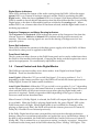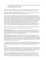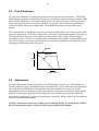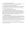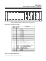
1
MODEL DA20
DIGITAL FILM
SOUND PROCESSOR
Users' Manual
Issue 4
Part No. 91342
USERS' MANUAL
FOR
MODEL DA20 DIGITAL
FILM SOUND PROCESSOR
Dolby Laboratories Incorporated
U.S.A. 100 Potrero Avenue, San Francisco, CA 94103
Tel: 415-558-0200; Fax: 415-863-1373
U.K. Wootton Bassett, Wilshire SN4 8QJ, England
Tel: +44 (0)1793 842100; Fax: +44 (0)1793 842101
www.dolby.com
WARRANTY INFORMATION—U.S.A.: warranty on the product covered by this manual is subject to the limitations and disclaimers set forth
in the warranty disclaimer originally shipped with the product and also printed on the back of the invoice.
All requests for repairs or information should include the unit serial number to ensure rapid service.
Note: This equipment has been tested and found to comply with the limits for a Class A digital device, pursuant to Part 15 of the FCC
Rules. These limits are designed to provide reasonable protection against harmful interference when the equipment is operated in a
commercial environment. This equipment generates, uses, and can radiate radio frequency energy and, if not installed and used in
accordance with the instruction manual, may cause harmful interference to radio communications. Operation of this equipment in a
residential area is likely to cause harmful interference in which case the user will be required to correct the interference at his own
expense.
Digital decoding covered by the following U.S. patents: 4,790,016, 4,914,701, 4,799,260 4,941,177, 5,109,417, 5,142,656, 5,230,038, 5,274,740,
5,297,236, 5,357,594, 5,463,424, 5,583,962, 5,608,805, and other worldwide patents granted and pending.
Dolby is a registered trademark of Dolby Laboratories.
©1997 Dolby Laboratories
ISSUE 4
S97/10410/11548
Dolby Part No. 91342
i
TABLE OF CONTENTS
INTRODUCTION
About this manual ........................................................................................................................................ ii
About the Dolby DA20 and the Dolby Stereo Digital Format ............................................................... ii
SECTION 1 OPERATING INSTRUCTIONS
1.1
1.2
1.3
1.4
1.5
1.6
1.7
How to Identify Sound Tracks on Prints ................................................................................. 1-1
Film Threading ............................................................................................................................ 1-2
Displays ........................................................................................................................................ 1-2
Format Control and Auto Digital Modes ................................................................................ 1-4
Single Projector Installations ..................................................................................................... 1-8
Two Projector Changeover Operation ..................................................................................... 1-8
Operation With an Automation System .................................................................................. 1-8
SECTION 2 MAINTENANCE AND ADJUSTMENTS
2.1
2.2
2.3
Digital Soundhead Maintenance .............................................................................................. 2-1
Print Cleanliness ......................................................................................................................... 2-2
Adjustments ................................................................................................................................. 2-2
SECTION 3 UNIT SERVICING/IN CASE OF DIFFICULTY
APPENDIX A
DA20 CIRCUIT BOARD LOCATIONS
ii
INTRODUCTION
Thank you for purchasing the Dolby Model DA20 Digital Film Sound Processor. It
combines the high performance for which all processors manufactured by Dolby
Laboratories are well known with the latest digital technology to decode the Dolby
Digital print format.
About this manual
This User’s Manual has been prepared specifically to help theater personnel get the most
from the Model DA20 and Cat. No.700 Digital Soundhead after proper installation.
Installation should be attempted only by qualified personnel. Installation and alignment
instructions are provided in a separate manual. We suggest that you keep this manual
readily available for quick reference.
The manual is organized as follows:
• Section 1, Operating Instructions, covers the basic control and indicator functions of
the DA20, and is all you need to get the show started.
• Section 2, Maintenance and Adjustments, contains tips for maintaining the DA20 and
the Cat. No.700 Soundhead in your theater system.
• Section 3, Troubleshooting, will help you track down problems in the digital sound
system without test equipment. It consists of procedures to follow to isolate and fix
simple problems.
• Appendix A contains circuit board location information.
For the sake of clarity, boldface type is used for all specific references to DA20 controls
and indicators and their labels, such as Digital Signal Level, and CP Status. CP refers to
Cinema Processor. In addition, indicator lights on the DA20 are referred to in the text as
LEDs (Light-Emitting Diodes).
About the Dolby DA20 and the Dolby Stereo Digital Format
The Dolby Model DA20 enables Dolby models CP45, CP55, CP65, CP200 and CP500
Cinema Processors to play the Dolby digital soundtrack format.
The Digital Film Sound System consists of a Cat. No.700 Digital Soundhead with cables
and the Model DA20 Digital Film Sound Processor. An additional Cat. No.700 Digital
Soundhead may be added for use in two projector changeover systems. The soundhead is
a mechanical assembly which provides a stable film path, and uses a CCD array to scan
digital data from a digital print. The DA20 decodes the scanned digital soundtrack into
six channels of high quality audio.
Among the features of the DA20 are:
• Automatic format selection between a Dolby digital track and the conventional analog
SR track.
• Display of digital signal level.
iii
• Adjustable time delay for mounting the Cat. No.700 Digital Soundhead up to 135
frames in advance of the analog soundhead.
• Adjustable surround delay to match theater size.
• Simple interface to the Dolby Cinema Processors.
• Comprehensive Cinema Processor status display.
• Automatic switching to analog soundtrack in the event of damaged or missing digital
data.
The DA20 includes interface cables to mate with the required Cinema Processor type.
Dolby Digital prints have conventional SR analog and digital tracks which enables lowcost 35mm optical prints to deliver the volume range, fidelity and discreteness previously
associated only with 70mm releases. The Dolby Digital format utilizes an innovative
digital encode/decode process, Dolby AC-3. The process translates five full range (20-20
kHz) channels plus a subwoofer audio channel and auxiliary data channel into a series of
data blocks, printed between the perforations of standard 35mm film. On playback, the
data blocks are scanned by an optical pickup head, and transformed back into full
professional quality digital audio. Release prints in the Dolby Digital format also contain
standard SR encoded Dolby Stereo analog tracks, resulting in single inventory prints and
unprecedented quality and reliability in film audio presentation.
This manual describes the operation of the DA20 when equipped with a Cat. No. 611A
Cinema Processor Interface card. The Cat. No. 611A has features that were not available
on the original Cat. No. 611. In particular, the automatic selection of Format 10 (Dolby
Digital), Format 05 assertions after a power failure, and other improvements are now
incorporated. Thus, the manual sections that describe the operation of auto digital and
power failure format assertion are not applicable to those units which are equipped with
the original Cat. No. 611 card.
To determine if a Cat. No. 611A is installed in your unit, look through the CP Status
opening on the DA20 front panel. If your unit is equipped with a Cat. No. 611A, you will
see “CAT. NO. 611A” printed on the PC board just inside the window immediately below
the “Analog” LED. Behind the text you will also see a cross hatched pattern printed on
the board. These two markings indicate that your unit is equipped with a Cat. No. 611A.
Your installer can provide details.
If your unit is not equipped with a Cat. No. 611A, the switch positions for Auto Digital
Disabled modes are not available and the CP Type is selected using positions 1 through 3
depending on which cinema processor is attached. See manual Section 1.4
a
1-1
SECTION 1
OPERATING INSTRUCTIONS
1.1
1.2
1.3
1.4
1.5
1.6
1.7
1.1
How to Identify Sound Tracks on Prints
Film Threading
Displays
Format Control
Single Projector Installations
Two Projector Changeover Operation
Operation With An Automation System
How to Identify Sound Tracks on Prints
A Dolby Digital film print or a stereo optical print (A-Type or SR), or a mono optical print
should be identified as such on both the film can and leader. However, with handling the
identification may be lost. If you are not sure if you have a stereo analog print, play a reel
and find a section with music and/or effects only (on dialogue or narration, stereo
soundtracks look much the same as mono soundtracks). Examine the soundtracks
closely; on music and effects, the two soundtracks will appear to be different on a stereo
print; on a mono print they are identical. If you specified a stereo print and received a
mono print in error, be sure to check with your local exchange or the film distributor.
a
Digital Print
The digital data blocks are
clearly visible between
perforations next to the
analog track. The analog
track is Dolby SR encoded.
Analog Dolby Stereo
Print
Clear differences
between channels will
be seen in some places
along the track.
Mono Print
Both tracks are the
same.
Figure 1.1 Film Sound Tracks
There is no way to tell by visual inspection if a stereo print has been encoded with a
surround channel or whether it is Dolby A-type or SR encoded. However, all but a few
early Dolby Stereo releases do have a surround channel. The majority of prints are now
Dolby SR encoded. If you are in doubt, play the print in format 04 Dolby A-type until
you have a chance to listen to the track and compare playback quality in formats 04 and
05.
1-2
1.2
Film Threading
The Cat. No. 700 Digital Soundhead is similar in many ways to a conventional analog
soundhead, having a lightweight flywheel, toothed sprocket, two pad rollers, and two
dashpot-damped tension arms. The pad rollers on the toothed sprocket are coupled to
allow easy film threading. A spring loaded roller arm damps variations in input film
tension. Bypass rollers are provided to bypass the soundhead with either 35 or 70 mm
film. Figure 1.2 shows Digital Soundhead film path threading. Care must be taken to
thread the film the same way every time, so that the distance from the optical pickup
point to the film gate is constant from show to show. Circuitry in the DA20 processor
delays the signal read at the optical pickup by an amount set during installation. The
threading must match this delay, or improper synchronization will result. NOTE: Film
tension is important. A proper loop is set when the tension arms match the white half
circles. The arms must not touch, or be too far apart (Approximately 5mm is correct).
Set film path so that top and bottom tension
arm rollers A are approximately 5 MM (1/4 inch) apart.
Use the white painted semi-circles B for angular alignment
of tension arms C . Make sure that the rollers do not touch.
C
B
A
A
B
C
Digital Print Threading Path
Bypass Threading Path
Figure 1.2 Film threading
1.3
Displays
The DA20 has eight slots in the front panel to allow sets of LEDs to be visible, indicating
the activity of various circuits. The large slot in the center is used as an error rate display
on a seven segment LED. Six of the slots show digital audio signal level, and the last
shows Cinema Processor Status. Each area will be discussed below.
1-3
Error Rate Display
1 = CP55
Auto Digital
2 = CP45/65/500
Auto Digital
3 = CP200
Auto Digital
5 = CP55
Auto Digital Disabled
6 = CP45/65/500
Auto Digital Disabled
7 = CP200
Auto Digital Disabled
Cinema Processor Type Switch
Output Signal
Present
Indicators
L
C
R
LS
RS
SW
Fixed Delay
100 perf
10 perf
1 perf
S
SR D
digital
analog
+10
+1
-1
-40
+10
+1
-1
-40
L
R
+10
+1
-1
-40
+10
+1
-1
-40
+10
+1
LS
-1
-40
+10
+1
RS
-1
-40
Digital Status
Indicators
C.P.
Status
C
SW
proj 1
motor 1
proj 2
motor 2
Proj C/O and
Motor Running
Indicators
Power
- 15
+15
+5
Digital Signal Level
Power Rail
Indicators
Surround Delay
X 10ms
Digital Signal Level
Indicators
Figure 1.3 DA20 Front Panel
Error Rate Display
Following powerup, with no film running, the seven-segment display will display a “-”
indicating no data on which to display error rate. When film is run, the display will show
error rate of the film on a scale of 0-8 with intermediate values indicated by the right hand
decimal point (0,0.,1,1.,2,2.,3,3.,4,4.5,5.,6,6.,7,7.,8,) where 0 is the lowest and 8 is the
highest. The display shows “F.” when an uncorrectable block is being processed.
Digital Signal Level Display
Digital audio signal levels are displayed for channels Left, Right, Left Surround, Right
Surround, Center and Subwoofer using four LEDs for each channel. The bottom LED in
each set shows audio activity less than –40dB below Dolby Digital level. Equal brightness
of the center two LEDs indicates “Dolby Digital level”, corresponding to an 85dB SPL in
the theater. The top LED indicates activity greater than +10dB above Dolby level when
lit. These LEDs show that digital audio from a Dolby Digital print is being decoded.
Signal Present Indicators
Signal Present Indicators are active when the signal level is approximately –40dB or
above (with respect to Dolby Digital Level). The LED brightness corresponds directly to
signal level. These Indicators represent the decoded analog signal level present at the
output of the DA20. In a system using a CP200 Cinema Processor, analog audio from the
cinema processor is routed through the DA20 to allow switching between the analog and
the digital tracks. The LEDs indicate the decoded digital signal level when the digital
status Indicators show that a digital track is selected, and the analog signal level when
analog track is indicated (see Digital status below). In a system using other Dolby cinema
processors, audio switching between analog and digital is performed within the Cinema
Processor, and the LEDs will reflect only decoded digital signal level.
1-4
Digital Status Indicators
These LEDs indicate the format of the audio coming from the DA20. When the upper
(green) LED is on, Format 10 has been selected, and the DA20 is producing decoded
digital audio. When the lower (yellow) LED is on, Format 10 has been selected but the
DA20 is unable to decode digital information from the film (either the film is not a Dolby
Digital print, or the data is unreadable) and has switched to the analog track. When
neither LED is on, a format other than 10 has been selected, and the digital audio track is
not being reproduced.
Projector Changeover and Motor Running Indicators
The Projector1 and Projector2 LEDs indicate the status of the changeover line from the
Cinema Processor. Motor1 and Motor2 LEDs indicate which projector motor(s) are
running. The motor running signals are used in the timing of changeovers in a two
projector system.
Power Rail Indicators
These LEDs indicate the presence of the three power supply rails in the DA20. All three
should be lit when power is applied to the DA20.
Front Panel Switches
The five rotary switches shown on the DA20 front panel are for use by technicians when
the DA20 is first installed and adjusted. Changing the delay switches requires the use of
special test equipment. Do not arbitrarily adjust these switches.
1.4
Format Control and Auto Digital Modes
The DA20 can operate in either of two basic modes: Auto Digital and Auto Digital
Disabled. These are described below:
Auto Digital—When the CP Type switch (See figure 1.3) is set to positions 1, 2 or 3,
depending on the cinema processor type, the DA20 will switch the cinema processor to
Dolby Digital, Format 10, under certain conditions.
Auto Digital Disabled—When the CP Type switch is set to position 5, 6 or 7, depending
on the cinema processor type, the format selection is controlled by the Cinema Processor
alone and the DA20 will assert no formats except when playing digital audio and a
reversion is required. Details of operation differ depending on the type of Cinema
Processor used and are described later.
When Format 10, Dolby Digital, is selected, the DA20 will output digital audio whenever
it is available. When the DA20 is playing digital audio, the green ‘Digital’ LED on the
DA20 front panel will light. When digital audio is not available (for example, while
playing an analog only film), the DA20 will switch the cinema processor to Format 05,
Dolby SR, if Format 10 was selected previously.
If the Dolby Digital track becomes corrupted beyond correction through perforation
damage, then error concealment techniques are applied for up to 4 perforations (40ms). If
the data is still unreadable, the DA20 then switches the Cinema Processor to Format 05
(Dolby SR). This is referred to as a ‘reversion to analog’ or simply ‘reversion’. Reversion
is indicated on the front panel of the DA20 when the yellow ‘Analog” LED lights. This
1-5
LED will also light if the cinema processor is in Format 10 and an analog only film is
played.
In order for the DA20 to switch the cinema processor back to Format 10 after a reversion,
the digital track must become correctable after a damaged section of film has passed, or
an un-damaged digital track must be played after an analog-only film. At this point, the
DA20 will switch the cinema processor back to Format 10 and the green “Digital” LED
will again light.
The operation of the DA20 with each Cinema Processor is described separately below:
CP55
When the CP Type switch is set to position 1, the DA20 will operate in CP55 Auto Digital
mode. In this mode, the DA20 will automatically switch the CP55 to Format 10 if the
following conditions exist:
• The DA20 detects that the CP55 is in a film format (01, 04, or 05).
• Dolby Digital audio is available.
• No format buttons are pressed.
If all of the above conditions exist, then the DA20 will automatically switch the CP55 to
Format 10, eliminating the need to cue Dolby Digital films or trailers. If a film format
button is pressed on the CP55 after the DA20 has automatically switched to Format 10,
the DA20 will switch the CP55 back to Format 10 after the button is released to keep the
CP55 in Format 10 as long as Dolby Digital audio is available. If digital audio is no longer
available, the DA20 will cause a reversion and switch the CP55 to Format 05. During a
reversion, any format can be selected on the CP55 and the DA20 will not assert any
formats. However, if the CP55 is in a film format and digital audio again becomes
available, the DA20 will switch the CP55 back to Format 10.
There are two methods by which to disable the automatic selection of Format 10. First,
the user can rotate the CP Type switch (see figure 1.3) to position 5. This disables the
ability of the DA20 to assert any format commands except those associated with
reversions (i.e. Format 05 when valid digital is lost and Format 10 when valid digital
returns).
In emergency situations, the user can press and hold the Format 05 button on the CP55 for
at least 4 seconds. After 4 seconds has elapsed, the green ‘Digital” LED on the DA20 will
go out. At this point, the CP55 will be in Format 05. Any format can be selected on the
CP55 front panel without the DA20 forcing the CP55 back into Format 10. Format 10 can
again be selected from the CP55 and the DA20 will go into Format 10.
To re-enable the automatic selection of Format 10 after it has been disabled by pressing
the Format 05 button for 4 seconds, either the DA20 must be turned off and then on again,
or the CP Type selector switch must be rotated out of and back into position 1.
CP45/CP65/CP500
When the CP Type switch (see figure 1.3) is set to position 2, the DA20 will operate in
CP45/CP65/CP500 Auto Digital mode. In this mode, the DA20 will automatically switch
the CP45/CP65/CP500 to Format 10 if the following conditions exist:
1-6
• The DA20 detects that the CP45/CP65/CP500 is in a film format (01, 04, or 05).
• Dolby Digital Audio is available.
• No format buttons are pressed.
If all of the above conditions exist, then the DA20 will automatically switch the cinema
processor to Format 10, eliminating the need to cue Dolby Digital films or trailers.
Exception - CP45s built before mid-1997: The DA20 will not automatically switch the
CP45 into Format 10 if Format 01 (mono) has been selected.
If all of the above conditions exist, then the DA20 will automatically switch the CP45/
CP65/CP500 to Format 10, eliminating the need to cue Dolby Digital films or trailers. If a
film format button is pressed on the CP45/CP65/CP500 after the DA20 has automatically
switched to Format 10, the DA20 will switch the CP45/CP65/CP500 back to Format 10
after the button is released to keep the CP45/CP65/CP500 in Format 10 as long as Dolby
Digital audio is available. If digital audio is no longer available, the DA20 will cause a
reversion and switch the CP45/CP65/CP500 to Format 05. During a reversion, any
format can be selected on the CP45/CP65/CP500 and the DA20 will not assert any
formats. However, if the CP45/CP65/CP500 is in a film format and digital audio again
becomes available, the DA20 will switch the CP45/CP65/CP500 back to Format 10.
There are two methods by which to disable the automatic selection of Format 10 on the
CP45/CP65 and one method on the CP500. These are described below:
CP45/CP65/CP500: The user can rotate the CP Type switch to position 6, CP45/CP65/
CP500 Auto Digital Disabled mode. This disables the ability of the DA20 to assert any
format commands except those associated with reversions (i.e., Format 05 when valid
digital is lost and Format 10 when valid digital returns).
CP45/CP65 only: In emergency situations the user can press and hold the Format 05
button on the CP45/CP65 for at least 4 seconds. After 4 seconds has elapsed, the green
‘Digital” LED on the DA20 will go off. At this point, the CP45/CP65 will be in Format 05.
Any format button on the cinema processor can be pressed without the DA20 forcing the
CP45/CP65 back into Format 10. Format 10 can again be selected from the CP45/CP65
and the DA20 will go into Format 10.
To re-enable the automatic selection of Format 10 after it has been disabled by pushing
the Format 05 button for 4 seconds, either the DA20 must be turned off and then on again
or the CP Type selector switch must be rotated away from and back to position 2.
CP200:
In order for the CP200 Auto Digital mode to operate, the DA20 must be connected to the
CP200 using a Cat493 Auto Digital Interface board and cable assembly. Since Format 10
can reside on any of the four format selectors on the CP200, the operation of the DA20
with this Cinema Processor is different from the above mentioned processors.
When power is first applied to the DA20 with the CP Type switch (see figure 1.3) set to
position 3 (CP200 Auto Digital mode), the DA20 will sequentially select formats A
through D on the CP200, looking for Format 10. The DA20 will scan the four format
selectors up to 10 times. If Format 10 is found on one of the format selectors, the DA20
1-7
will remember which format selector is set to Format 10 and will select this format
whenever the CP200 is in any film format and valid digital audio is. If Format 10 is not
detected on one of the format selectors, the DA20 will operate in Auto Digital Disabled
mode. Once this occurs, if the user wishes to enable the Auto Digital mode, one of the
CP200 format selectors must be programmed to Format 10 and the CP Type switch on the
DA20 must be rotated out of and then back into position 3. This will cause the DA20 to
again scan the CP200 format selectors.
As soon as the DA20 detects Format 10 on one of the format selectors, it will stop
scanning the CP200 format selectors, and begin Auto Digital operation. In either case, the
CP200 will be left in whatever format is selected by selector D, regardless of the wakeup
format chosen on the CP200.
If Format 10 is detected on one of the format selectors, the DA20 will automatically assert
that format whenever the following conditions are met:
• The DA20 detects that the CP200 is in Format 01, 04, or 05.
• Digital audio is available.
If all of the above conditions exist, the DA20 will automatically assert Format 10 thus
eliminating the need to cue Dolby Digital films or trailers. If a different film format is
selected on the CP200 while valid digital audio is available, the DA20 will again select
Format 10 to keep the CP200 in Format 10.
After the DA20 has switched the CP200 to Format 10, if valid digital audio is no longer
available, the DA20 will cause a reversion. Though the format selector on the CP200
which is programmed to Format 10 will remain selected, the yellow ‘Analog” LED will
light and the audio signal path will switch to the analog SR track. At this point, an
automation system or operator can assert any format. The DA20 will not re-assert Format
10 until digital audio is again available.
To disable the automatic selection of Format 10 by the DA20, two methods are provided
in CP200 installations.
First, the CP Type switch can be set to position 7 (CP200 Auto Digital Disabled). This
disables the ability of the DA20 to assert any format commands except those associated
with analog reversions when in Format 10.
In emergency situations , the ‘GO’ button on the CP200 can be pressed and held for at
least 4 seconds. After 4 seconds has elapsed, the green ‘Digital” LED on the DA20 will go
off and the ‘Analog’ LED will flash. At this point, the CP200 will be playing the analog
SR track and any format can be selected without the DA20 forcing the CP200 back into
Format 10. If Format 10 is again selected, the DA20 will remain in analog mode thus
forcing the CP200 to play the analog SR track. Auto-digital mode can not be re-enabled
unless the DA20 is turned off and then on again or the CP Type switch is rotated out of
and back into position 3. This will cause the DA20 to re-scan the CP200 format selectors
and look for Format 10 again and therefore should not be done while film is playing.
1-8
1.5
Single Projector Installations
In single projector installations, the Proj 1 motor start input is normally grounded with a
jumper. Presence of this conection is shown by a continuously illuminated Proj 1 led on
the Cat. No. 611. If this connection is not present, a fault in the digital data will not cause
the system to switch to analog; it will just go silent. For this reason it is very important to
jumper pin 1 to pin 5 on the motor start connector J9 in a single projector system.
1.6
Two Projector Changeover Operation
The DA20 “changes over” between Cat. No.700 Digital Soundheads by switching
between digital data signals at a time in advance of the actual picture changeover. The
data on the film is read by the Digital Soundhead ahead of the picture gate by typically
1-1/2 seconds. A delay circuit in the DA20, set during installation, compensates for this
“early” reading of data. In order for a changeover to be seamless, the switchover to the
incoming digital data must happen “early” as well. The Motor Start signal (a contact
which closes when power is applied to the projector) is used to initiate the digital
changeover. Digital changeover occurs at eight seconds minus the amount of delay set at
installation. Eight seconds is the time between the motor start cue at the end of a reel and
the last picture frame on that reel. If the Digital Soundhead were located at the analog
soundhead position, no fixed delay would be required, and the digital changeover would
happen simultaneously with the picture changeover. Any amount of delay added to the
digital signal to compensate for “early reading” (ahead of the analog soundhead) must be
subtracted from the 8 seconds to get the time that the digital signal must be switched after
the motor start.
1.7
Operation With an Automation System
The DA20 may be used in conjunction with any standard automation system, but the
following guidelines must be followed:
To select Dolby Stereo Digital, format 10 must be selected. If no valid digital data is
present, either due to an analog only print or to problems reading the digital track, the
DA20 Cinema Processor system will automatically switch to format 05, Dolby SR.
When used with a CP45, CP55, CP65, or CP500, the automation system must use
momentary Cinema Processor format select lines. The DA20 senses and controls these
lines to switch between digital and analog as required. If format lines are held
continuously, incorrect operation will result, and this situation will need to be corrected.
When used with a CP200 Cinema Processor, the automation system controls the Cinema
Processor. It, in turn, sends a signal to the DA20 indicating that digital sound is desired.
The DA20 responds with a green LED located on the DA20 front panel indicating that
digital audio has been decoded and is present on its output lines. If valid digital data is
not available, a yellow LED will be on.
2-1
SECTION 2
MAINTENANCE AND ADJUSTMENTS
2.1
2.2
2.3
2.1
Digital Soundhead Maintenance
Print Cleanliness
Adjustments
Digital Soundhead Maintenance
The Cat. No.700 Digital Soundhead should be kept clean and free of dust and dirt for best
performance, just like your analog soundhead. Wiping the external surfaces with a clean
cloth on a regular basis will keep the head looking new. The optical path should be
inspected regularly and kept clean with a photographer’s lens cleaning kit (available from
most camera stores). Use care not to scratch the lens. The film path (rollers and drum)
should be cleaned regularly, as you would on the projector. No acetone, carbon
tetrachloride, or other dangerous cleaners should be used.
Replacing the Exciter Lamp
The exciter lamp in your Cat. No.700 Digital Soundhead has been designed for long life
and should provide over 8000 hours of reliable use under normal circumstances.
Routine replacement will depend on your theater’s hours of operation. To replace the
exciter lamp, carefully remove the six screws holding the rear cover/power supply of the
Digital Soundhead. Allow the lamp to cool if necessary. With the rear cover removed,
the lamp will be visible but still attached to the rear cover assembly by its two supply
wires. Slide the lamp out of its base. Carefully remove a new lamp from the protective
box, and using gloves or a clean, lint-free cloth, replace the lamp in the socket. Be careful
not to touch the bulb or inner surface of the reflector in the lamp. If either is accidentally
touched, carefully clean the area with isopropyl alcohol when the bulb is cool. Slide the
lamp back into its base in the soundhead, replace the rear cover assembly and tighten the
six screws.
Replacement lamp:
Use only General Electric EPT
Reflector-type
42W
Dolby Part No. 34010
Figure 2.1 Digital Soundhead Exciter Lamp Replacement
2-2
2.2
Print Cleanliness
As with any soundtrack, keeping the print clean will give best performance. The Dolby
Digital print format has robust error correction information encoded along with the audio
data, and the DA20 uses a powerful digital error correction technique, allowing the data
to be read perfectly even if scratches and dirt are present. However, best performance
will be obtained if the print is kept clean. Standard film cleaners will provide good
results.
The sound quality of the digital track has properties unlike those of an analog track with
regard to print wear. With any analog track, print wear will degrade quality in a more or
less linear fashion; the more wear, the lower the quality of the sound. With a digital
soundtrack, wear will have no audible effect until the picture quality is degraded beyond
use. At this point, wear may exceed the error correction capabilities of the decoder, and
switching to the analog track will occur.
DIGITAL
ANALOG
(Sound & Picture)
Quality
Number of plays
2.3
Adjustments
Routine adjustments are not required on the DA20 under normal use. Adjustments for
cinema processor type, soundhead delay, surround delay, focus, and film path alignment
are made during installation, and should not be attempted by the operator. Small
adjustments may not affect the sound under most circumstances, and no changes will be
heard, but improper adjustment may reduce the safe operating area within which all
errors can be corrected. Proper test equipment is required. Refer to the DA20 Installation
manual for further information.
Caution: There are no user serviceable parts inside the DA20. To avoid electric shock,
do not attempt any repairs. Refer all servicing to qualified personnel.
3-1
SECTION 3
UNIT SERVICING / IN CASE OF DIFFICULTY
3.1
Troubleshooting During the Show
Your theater sound system consists of a number of critical audio components in addition
to the Dolby DA20 system. Thus, the first step when something goes wrong with the
sound is to find the source of the problem. The troubleshooting chart for your cinema
processor can be very helpful. If indications are that the fault lies in the DA20, the
procedures in the following paragraphs may be useful.
If you are unable to solve the problem using the information which follows, call your
service engineer. If he or she is unavailable, you may also call Dolby Laboratories’ 24
hour emergency number in San Francisco for expert advice: (415) 558-0200. You will be
asked to leave your name and number, and a Dolby Engineer will call you back promptly.
1.
If Digital Sound is Lost
• Switching to the analog track will occur if the Digital Soundhead is playing film
which is not in Dolby Digital format, or if the digital blocks have become unreadable
due to an obscured optical path or print damage. If frequent switching occurs, check
for print and optical path cleanliness.
• Check to make sure power is supplied to the DA20 processor chassis and the Digital
Soundhead exciter lamp.
• If power is present at the Digital Soundhead, but the exciter lamp is not lit, the lamp
needs to be replaced. Refer to page 2-1 for information on replacing the exciter lamp.
• If you are sure that power is applied to the DA20, but no LEDs on the front panel are
on, check the fuse in the power entry module on the rear of the DA20. If it appears
blown, replace with a spare fuse of the type and value specified on the rear panel of
the DA20.
• Check the video cable(s) from the Digital Soundhead(s) to the DA20 and make sure
both ends are properly attached.
• If the Auto Digital feature is enabled, disable it using the following method:
CP45 / CP55 / CP65—If the Auto Digital feature is enabled, disable it using the
following method:
CP200—Press and hold the “GO” button on the CP200 for at least 4 seconds. The
“Digital” LED on the DA20 will go off.
CP500—Rotate the CP Type switch located on the DA20 front panel to position 6.
3-2
2.
If One Channel Fails or is Distorted
This is unlikely to be a fault of the DA20. Check for analog audio path continuity. If the
problem is isolated to the DA20, contact your authorized Service Engineer.
3.
If Switching to Analog Does Not Restore Sound
If switching to analog occurs when in Format 10 (indicated by the yellow Analog LED on
the DA20 front panel), but no analog sound is heard, FIRST select Format 05 (SR) by
means of the Cinema Processor format selector switches. If this doesn’t work, remove
power to the DA20 and reselect Format 05.
4.
If Difficulty with Changeover is Experienced
Correct changeover operation relies on installation of two relays which close sets of
contacts when each projector motor is running. The normally open (closed when
projector is running) contacts on these relays must be attached to connector J9 on the rear
panel of the DA20. (Refer to Installation manual for further information.) In addition, a
changeover signal from the Cinema Processor must be present and connected to the
DA20. Correct operation of these signals may be observed by monitoring the Proj1,
Motor1, Proj2, and Motor2 LEDs on the front panel of the DA20.
5.
If Synchronization is Lost
Synchronization of the digital soundtrack with the picture requires that the film path
from the Soundhead to the picture gate be the same every time the projector is threaded.
If two projectors are used, the path lengths must be identical. Digital Soundhead delay is
set by switches on the Cinema Processor Interface Card (Cat. No.611A). If
synchronization becomes incorrect during a show, press Format 10. This re-sends a delay
turn-on command to the Cat No. 611A. If this does not solve the problem, then play the
rest of the show in Analog, Format 05, and when time permits, run a loop of Cat. No.1010
Digital Soundhead Test Film and adjust the delay as described in Section 3.
If none of the above techniques solves your problem, make sure the Cinema Processor is
not in format 10, and try cycling the power to the DA20. This will reset the DA20 and
may cure a transitory problem.
A-1
APPENDIX A
DA20 CIRCUIT BOARD LOCATIONS
670 671
671 673
674 675
686
611A
Caution: Remove power before removing or inserting circuit boards.
(Left to right, facing front of DA20):
Slot
Number
1
2
3
4
5
6
7
8
9
10
11
12
13
14
15
16
17
18
19
20
21
Cat.
No.
670
671
671
673
674
675
686
611A
Description
Empty
reserved
reserved
reserved
reserved
reserved
reserved
reserved
reserved
reserved
reserved
Video Front End board
Dual DSP board
Dual DSP board
System Services board
LED board (mounted on 675)
AC-3 decoder DSP board
Hex DAC board
CP Interface board
Empty
Empty
In the Cat. 700 Digital Soundhead:
Cat. No.634 CCD (Charge Coupled Device) board