1
PROFESSIONAL
POWER AMPLIFIERS
7301 Professional Power Amplifier
Clip/Limit
10004 Professional Power Amplifier
Signal
Temp/DC
Active
-6
-10
-6
-3
-10
-15
-3
-15
-1
-30
-80
-1
-30
0dB
-80
LOWS
-6
-3
-10
-15
-1
-80
-80
0dB
-6
-10
-3
-80
-1
-30
-80
0dB
0dB
-1
-30
-80
0dB
Ch D
Ch C
Ch B
-3
-15
-15
-1
-30
0dB
Ch A
-1
-30
-80
Ch A
-10
-3
-15
-1
-30
-3
-6
-6
-10
-3
-15
-30
Active
-6
-10
-15
Active
-10
Signal
Temp/DC
Active
Signal
Temp/DC
-6
Signal
Temp/DC
7001 Professional Power Amplifier
Clip/Limit
Clip/Limit
Clip/Limit
0dB
HIGHS
0dB
Ch B
10001 Professional Power Amplifier
6001 Professional Power Amplifier
Clip/Limit
Signal
Temp/DC
Active
-6
-10
-6
-3
-10
-15
-3
-80
-1
-30
0dB
Signal
Signal
-80
Ch A
Clip/Limit
Clip/Limit
-15
-1
-30
0dB
Ch B
Temp/DC
Temp/DC
Active
Active
4801 Professional Power Amplifier
Clip/Limit
-3
-15
-1
-80
-1
-30
-80
0dB
0dB
Ch B
Ch A
Active
-6
-10
-10
-3
-30
Temp/DC
-6
-3
-10
-15
-6
-6
-10
-15
Signal
-3
-15
-1
-30
-80
-1
-30
0dB
-80
Ch A
9001 Professional Power Amplifier
0dB
Ch B
Clip/Limit
4601 Professional Power Amplifier
Clip/Limit
Signal
Signal
Temp/DC
Temp/DC
Active
Active
-6
-10
-6
-3
-10
-15
-6
-3
-10
-15
-1
-30
-80
-30
0dB
-80
Ch A
-6
-10
-3
-15
-1
-30
-80
0dB
-3
-15
-1
-80
0dB
Ch A
Ch B
-1
-30
0dB
Ch B
3301 Professional Power Amplifier
Clip/Limit
8001 Professional Power Amplifier
Signal
Temp/DC
Active
-6
-10
Clip/Limit
-6
-3
-10
-3
Signal
-15
-15
-1
-30
-80
-1
-30
0dB
-80
Ch A
Temp/DC
0dB
Active
Ch B
-6
-10
MA7120 Professional Power Amplifier
Clip/Limit
-80
-6
-10
-1
-30
-80
0dB
Ch A
Temp/DC
Active
-3
-15
-1
-30
Signal
0dB
Ch B
-6
-3
-10
-15
-6
-10
-3
-15
-3
-15
-1
-30
-80
-80
Ch A
MA9130
-1
-30
0dB
Professional Power Amplifier
0dB
Ch B
Clip/Limit
Signal
MA5850 Professional Power Amplifier
Clip/Limit
Temp/DC
Signal
Active
Temp/DC
-6
Active
-6
-10
-3
-10
-6
-10
-15
-3
-1
-30
-80
0dB
Ch A
-1
-80
-6
0dB
-3
-15
-1
-30
-30
-10
-3
-15
-15
-80
0dB
Ch A
-1
-30
-80
0dB
Ch B
Ch B
OWNER’S MANUAL
Including MA Series Amplifiers
Important Precautions
This symbol is used to alert the operator to follow important operating procedures and precautions detailed in
documentation.
This symbol is used to warn operators that uninsulated “dangerous voltages” are present within the equipment enclosure that may pose a risk
of electric shock.
1. Save the carton and packing material
even if the equipment has arrived in
good condition. Should you ever need
to ship the unit, use only the original
factory packing.
2. Read all documentation before operating your equipment. Retain all documentation for future reference.
3. Follow all instructions printed on unit
chassis for proper operation.
4. Do not spill water or other liquids
into or on the unit, or operate the unit
while standing in liquid.
5. Make sure power outlets conform to
the power requirements listed on the
back of the unit.
6. Do not use the unit if the electrical
power cord is frayed or broken. The
power supply cords should be routed so
that they are not likely to be walked on
or pinched by items placed upon or
against them, paying particular attention to cords and plugs, convenience
receptacles, and the point where they
exit from the appliance.
7. Always operate the unit with the AC
ground wire connected to the electrical system ground. Precautions should
be taken so that the means of grounding
of a piece of equipment is not defeated.
8. Mains voltage must be correct and
the same as that printed on the rear
of the unit. Damage caused by connection to improper AC voltage is not covered by any warranty.
9. Have gain controls on amplifiers
turned down during power-up to prevent speaker damage if there are high
signal levels at the inputs.
10. Power down & disconnect units from
mains voltage before making connections.
11. Never hold a power switch in the
“ON” position if it won’t stay there
itself!
12. Do not use the unit near stoves, heat
registers, radiators, or other heat
producing devices.
13. Do not block fan intake or exhaust
ports. Do not operate equipment on a
surface or in an environment which may
impede the normal flow of air around
the unit, such as a bed, rug, weathersheet, carpet, or completely enclosed
rack. If the unit is used in an extremely
dusty or smoky environment, the unit
should be periodically “blown free” of
foreign matter.
14. Do not remove the cover. Removing
the cover will expose you to potentially
dangerous voltages. There are no user
serviceable parts inside.
15. Connecting amplifier outputs to
oscilloscopes or other test equipment
while the amplifier is in bridged mode
may damage both the amplifier and test
equipment!
20. Non-use periods. The power cord of
equipment should be unplugged from
the outlet when left unused for a long
period of time.
21. Service Information E q u i p m e n t
should be serviced by qualified service
personnel when:
A. The power supply cord or the plug
has been damaged;
B. Objects have fallen, or liquid has
been spilled into the equipment;
C. The equipment has been exposed to
rain;
D. The equipment does not appear to
operate normally, or exhibits a
marked change in performance;
E. The equipment has been dropped, or
the enclosure damaged.
22. To obtain service, contact your nearest
Crest Audio Service Center, Distributor,
Dealer, or Crest Audio at 201.909.8700
(USA).
16. Do not drive the inputs with a signal
level greater than that required to
drive equipment to full output.
17. Do not connect the inputs / outputs of
amplifiers or consoles to any other
voltage source, such as a battery, mains
source, or power supply, regardless of
whether the amplifier or console is
turned on or off.
18. Do not run the output of any amplifier channel back into another channel’s input. Do not parallel- or seriesconnect an amplifier output with any
other amplifier output. Crest Audio is
not responsible for damage to loudspeakers for any reason.
19. Do not ground any + (“hot”) terminal. Never connect a + (“hot”) output
to ground or to another + (“hot”) output!
All Professional Series power amplifier
models are UL LISTED, except for:
10001
10004
MA5850
MA7120
MA9130
Power Amplifier Owner’s Manual
Table of Contents
Introduction . . . . . . . . . . . . . . . . . . . . . . . . . . . . . . . . . 2
Unpacking . . . . . . . . . . . . . . . . . . . . . . . . . . . . . . . . . . 2
Mounting . . . . . . . . . . . . . . . . . . . . . . . . . . . . . . . . . . . 2
Cooling Requirements . . . . . . . . . . . . . . . . . . . . . . . . . 3
Operating Precautions. . . . . . . . . . . . . . . . . . . . . . . . . . 3
Crest Audio Model 7301 Power Amplifier . . . . . . . . . . 3
Crest Audio Model 10004 Power Amplifier . . . . . . . . . 3
Models 3301, 4801, 6001 Features . . . . . . . . . . . . . . . . 4
Model 4601 Features . . . . . . . . . . . . . . . . . . . . . . . . . . 4
Model 7001 Features . . . . . . . . . . . . . . . . . . . . . . . . . . 5
Model 7301 Features . . . . . . . . . . . . . . . . . . . . . . . . . . 5
Model 8001 Features . . . . . . . . . . . . . . . . . . . . . . . . . . 6
Model 9001 Features . . . . . . . . . . . . . . . . . . . . . . . . . . 7
Model 10001 Features . . . . . . . . . . . . . . . . . . . . . . . . . 8
Model 10004 Features . . . . . . . . . . . . . . . . . . . . . . . . . 9
Connecting Inputs. . . . . . . . . . . . . . . . . . . . . . . . . . . . 10
Connecting Outputs . . . . . . . . . . . . . . . . . . . . . . . . . . 10
Crest Audio Octal Sockets . . . . . . . . . . . . . . . . . . . . . 10
NexSys® . . . . . . . . . . . . . . . . . . . . . . . . . . . . . . . . . . . 10
Connecting Power. . . . . . . . . . . . . . . . . . . . . . . . . . . . 11
Operation Modes . . . . . . . . . . . . . . . . . . . . . . . . . . . . 11
Bridging Precautions . . . . . . . . . . . . . . . . . . . . . . . . . 12
Switches and Controls . . . . . . . . . . . . . . . . . . . . . . . . 12
Indicators . . . . . . . . . . . . . . . . . . . . . . . . . . . . . . . . . . 13
Protection Features . . . . . . . . . . . . . . . . . . . . . . . . . . . 13
Speaker Protection . . . . . . . . . . . . . . . . . . . . . . . . . . . 15
Amplifier Maintenance and User Responsibility . . . . . 15
Service/Warranty Information . . . . . . . . . . . . . . . . . . . 15
Professional Series Block Diagram . . . . . . . Appendix A
General Amplifier Specifications . . . . . . . . . Appendix B
Wire Gauge Charts. . . . . . . . . . . . . . . . . . . . Appendix C
Meyer-Compatible Power Amplifiers . . . . . . Appendix D
Crest Audio Pro Series Power Amplifiers
Page 1
Introduction
Congratulations...on your purchase of a Crest Audio Professional Series power amplifier. Designed for years of reliable, flawless operation under rigorous use. These power amplifiers offer the sonic superiority and unsurpassed reliability for which Crest Audio is
famous, while remaining surprisingly compact. Advanced technology and extensive protection circuitry allow operation with greater
efficiency into difficult loads and power conditions. All Professional Series amplifiers are fully compatible with Crest Audio’s Octal
Socket Accessories and the NexSys computer-controlled audio system. The IGM (Instantaneous Gain Modulation) circuit ensures trouble-free operation into loads as low as 2Ω. The clip limiting circuits protect drivers and ensure that sonic integrity is maintained, even
in extreme overload conditions. Crest Audio’s high-efficiency design uses tunnel-cooled heatsinks and variable speed DC fans. This
cooling topology maintains a lower overall operating temperature, resulting in longer output transistor life.
Model 9001, 10001, and 10004 power amplifiers use Crest Audio’s innovative “Power Density” circuitry.
Although the Crest Audio Professional Series amplifiers are quite simple to operate, and are housed in ultra-strong steel chassis,
improper use can be dangerous. Some of these models are very high-powered amplifiers that can put out high voltages and sizable currents at frequencies up to 30 kHz. Always use safe operating techniques with these amplifiers. FOR YOUR SAFETY, READ THE
IMPORTANT PRECAUTIONS SECTION , AS WELL AS INPUT, OUTPUT, AND POWER CONNECTION SECTIONS.
Unpacking
Upon unpacking, inspect the amplifier. If you find any damage, notify your supplier immediately. Only the consignee may institute a
claim with the carrier for damage incurred during shipping. Be sure to save the carton and all packing materials. Should you ever need
to ship the unit back to Crest Audio, one of its offices, service centers, or the supplier, use only the original factory packing. If the shipping carton is unavailable, contact Crest to obtain a replacement.
Mounting
Professional Series power amplifiers will mount in standard 19-inch racks having sufficient depth. The 10004 & 10001 amplifiers are
four rack units high; the 9001 and 8001 models are three rack-spaces high, while the remainder are two rack-space units. All two and
three-rack space units (except for the 9001) are provided with four front panel mounting holes. The 9001, 10001, and 10004 have eight
front panel mounting holes. Crest Audio recommends using all mounting holes to secure the power amplifier in the rack; this will
ensure the safety of the equipment. Rear mounting ears are also provided on all amplifiers for additional support, which is essential in
non-permanent installations like mobile or touring sound systems, but recommended for permanent installations as well. Because of
the cables and connectors on the rear panel, a right-angle or offset screwdriver or hex key will make it easier to fasten the rear mounting ears to the rails.
Note: The 10001 and 10004 models, because of their size, require rack mounting screws stronger than standard rack screws. For customers in the USA, these are supplied with the unit. Customers in Europe and Asia should mount these models using heavy-duty metric bolts.
Page 2
Crest Audio Pro Series Power Amplifiers
Cooling Requirements
The Professional Series amplifiers use a forced-air cooling system to maintain a low, even operating temperature. Air is drawn into the
amplifier by fan(s) on the rear panel, courses through the cooling fins of the back-to-back (tunnel-configured) channel heat sinks, and
then exhausts through the front panel slots.
If either heat sink gets too hot, its sensing circuit will open the output relay, disconnecting the load from that particular channel. If the
power transformer overheats, another sensing circuit opens the output relays on all channels until it cools to a safe temperature.
It is important to have an adequate air supply at the back of the amplifier and enough space around the front of the amplifier to allow
the cooling air to escape. If the amp is rack mounted, do not use doors or covers on the front of the rack; the exhaust air must flow
without resistance. If you are using racks with closed backs, use fans on the rear rack panel to pressurize the rack and ensure an ample
air supply; also make sure that there is one (1) standard rack space opening for every three mounted power amplifiers.
The Professional Series amplifiers are supplied with cooling fan air filters. The filters snap in place over the fan housing. Any filter will
decrease airflow somewhat, so use the filter only when the amplifier is used in a dusty environment without a filtered air supply. The
filter element must be cleaned or replaced periodically (see the section on Amplifier Maintenance for filter service procedures).
Operating Precautions
Make sure the mains voltage is correct and is the same as that printed on the rear of the amplifier. Damage caused by connecting the
amplifier to improper AC voltage is not covered by any warranty. See the Connecting Power section for more information on voltage
requirements.
Note: Always turn off and disconnect the amplifier from mains voltage before making audio connections. Also, as an extra precaution,
have the attenuators turned down during power-up.
Although the Professional Series amplifiers have AutoRamp circuitry, which raises the signal level gradually after the output relay closes, it is always a good idea to have the gain controls turned down during power-up to prevent speaker damage if there is a high signal
level at the inputs. Whether you buy or make them, use good-quality connections, input cables, and speaker cables, along with good
soldering technique, to ensure trouble-free operation. Most intermittent problems are caused by faulty cables.
Consult the Wire Gauge Charts to determine proper gauges for different load impedances and cable lengths. Remember that cable resistance robs amplifier power in two ways: power lost directly to resistance (I2R loss), and by lowering the total load impedance. Also
make sure the mode switch is correctly set for the desired application. See Sections on Stereo, Parallel, and Bridged Mono Operation
for more information.
The Crest Audio Model 7301 Power Amplifier
The Model 7301 is specifically designed for use in bi-amplified systems; because of its dissimilar channel design, the specifications
are reported in a separate fashion. The 7301 power specifications were obtained by driving the low frequency channel with a 100 Hz
signal and the high frequency channel with a 1 kHz signal.
The Crest Audio Model 10004 Power Amplifier
The Model 10004 power amplifier is unique in that it is a high-power, four-channel amplifier. Offering the advantages of Crest Audio’s
Power Density engineering design philosophy, this amplifier provides 1400 watts at 2Ω from each of the four channels. All four channels have independent LED indicators, attenuation, and input /output connections. Power switching and NexSys interfaces are configured in pairs of two. Because a channel may have to drive more than one speaker line, each channel has two pairs of output binding
posts. The red binding posts are hot (+), while the black binding posts are at signal ground (-).
Crest Audio Pro Series Power Amplifiers
Page 3
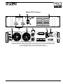
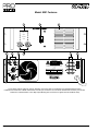
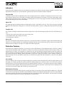
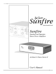
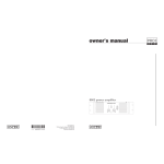
Models 3301, 4801, 6001 Features
1
2
3
3301 Professional Power Amplifier
Clip/Limit
Signal
Temp/DC
Active
-6
-10
-6
-3
-10
-15
-3
-15
-1
-30
-80
-1
-30
0dB
-80
Ch A
0dB
Ch B
4
5
6
7
9
8
10
CAUTION
AVIS : RISQUE DE CHOC ÉLECTRIQUE—NE PAS OUVRIR
A
+
BRIDGE
--
WARNING TO REDUCE THE RISK OF FIRE OR ELECTRIC SHOCK DO NOT
EXPOSE THIS EQUIPMENT TO RAIN OR MOISTURE.
PIN 3+
ATTENTION! POUR ÉVITER LE RISQUE D'INCENDIE OU DE CHOC
ÉLECTRIQUE, NE PLACEZ PAS CET APPAREIL SOUS LA PLUIE OU Á
L'HUMIDITÉ
A
OUT B
PUSH
IN
OUT A
RISK OF ELECTRIC SHOCK
DO NOT OPEN
STEREO
PARALLEL
BRIDGE
SIGNAL
GROUND
LIFT
Designed & manufactured in the USA by:
USA ONLY
B
B
PUSH
IN
MODEL #
MAXIMUM
INPUT CURRENT
@ 120V, 60Hz
OUTPUT POWER
IN WATTS PER
CHANNEL, 4Ω
3301
11 AMPS
330W
Crest Audio Inc.
100 Eisenhower Dr.
Paramus, New Jersey 07652 USA
OUTPUT - CLASS 2 WIRING MAY BE USED
1-Channel A & B Clip/Limit, Signal, Temp/DC, and Active LEDs. 2-Combination Circuit Breaker/Power Switch. 3-Heated Air Exhaust Grill.
4-Fan Intake Grill & Filter 5-Channel A & B Gain Attenuators. 6-Channel A & B XLR Input Connectors. 7-Mode Select Switch.
8-Crest Audio Octal Accessory Sockets. 9-Signal Ground Lift Barrier Strip. 10-Five-Way Output Binding Post Connectors.
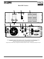
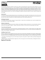
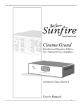
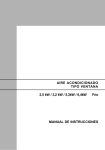
Model 4601 & 7001 Features
1
2
3
4601 Professional Power Amplifier
Clip/Limit
Signal
Temp/DC
Active
-6
-10
-3
-15
-1
-80
-1
-30
0dB
-80
Ch A
5
-3
-15
-30
4
-6
-10
0dB
Ch B
6
7
8
9
CAUTION
PARALLEL
STEREO
BRIDGE
OUT A
RISK OF ELECTRIC SHOCK
DO NOT OPEN
A
PIN 3+
A
+
BRIDGE
--
AVIS : RISQUE DE CHOC ÉLECTRIQUE—NE PAS OUVRIR
WARNING TO REDUCE THE RISK OF FIRE OR ELECTRIC SHOCK DO NOT
EXPOSE THIS EQUIPMENT TO RAIN OR MOISTURE.
ATTENTION! POUR ÉVITER LE RISQUE D'INCENDIE OU DE CHOC
ÉLECTRIQUE, NE PLACEZ PAS CET APPAREIL SOUS LA PLUIE OU Á
L'HUMIDITÉ
PUSH
IN
10
OUT B
SIGNAL
GROUND
LIFT
USA ONLY
B
PUSH
IN
B
Designed & manufactured in the USA by:
MODEL #
MAXIMUM
INPUT CURRENT
@ 120V, 60Hz
OUTPUT POWER
IN WATTS PER
CHANNEL, 4Ω
4601
18 AMPS
425W
OUTPUT - CLASS 2 WIRING MAY BE USED
Crest Audio Inc.
100 Eisenhower Dr.
Paramus, New Jersey 07652 USA
1-Channel A & B Clip/Limit, Signal, Temp/DC, and Active LEDs. 2-Combination Circuit Breaker/Power Switch.
3-Heated Air Exhaust Grill. 4-Mode Select Switch. 5-Channel A & B XLR Input Connectors. 6-Channel A & B Gain Attenuators.
7-Fan Intake Grills & Filters. 8-Crest Audio Octal Accessory Sockets
9-Signal Ground Lift Barrier Strip. 10-Five-Way Output Binding Post Connectors.
Page 4
Crest Audio Pro Series Power Amplifiers
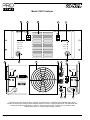
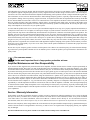
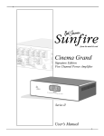
Model 7301 Features
1
2
3
7301 Professional Power Amplifier
Clip/Limit
Signal
Temp/DC
Active
-6
-10
-3
-15
-3
-15
-1
-30
-80
-1
-30
0dB
-80
LOWS
4
-6
-10
0dB
HIGHS
5
6
7
8
CAUTION
9
OUT LOWS
RISK OF ELECTRIC SHOCK
DO NOT OPEN
LOWS
AVIS : RISQUE DE CHOC ÉLECTRIQUE—NE PAS OUVRIR
WARNING TO REDUCE THE RISK OF FIRE OR ELECTRIC SHOCK DO NOT
EXPOSE THIS EQUIPMENT TO RAIN OR MOISTURE.
IN
LOWS
PUSH
ATTENTION! POUR ÉVITER LE RISQUE D'INCENDIE OU DE CHOC
ÉLECTRIQUE, NE PLACEZ PAS CET APPAREIL SOUS LA PLUIE OU Á
L'HUMIDITÉ
IN
HIGHS
PUSH
MODEL #
7301
HIGHS
USA ONLY
MAXIMUM
INPUT CURRENT
@ 120V, 60Hz
21 AMPS
OUT HIGHS
SIGNAL
GROUND
LIFT
PIN 3+
Designed & manufactured in the USA by:
OUTPUT POWER
IN WATTS PER
CHANNEL, 2Ω
CH. A 990W
{ CH.
B 220W
OUTPUT - CLASS 2 WIRING MAY BE USED
Crest Audio Inc.
100 Eisenhower Dr.
Paramus, New Jersey 07652 USA
1-Lows and Highs Channel Clip/Limit, Signal, Temp/DC, and Active LEDs. 2-Combination Circuit Breaker/Power Switch.
3-Heated Air Exhaust Grill. 4-Lows and Highs Channel XLR Input Connectors. 5-Lows and Highs Channel Attenuators.
6-Fan Intake Grills & Filters. 7-Crest Audio Octal Accessory Sockets.
8-Five-Way Output Binding Post Connectors. 9-Signal Ground Lift Barrier Strip.
Crest Audio Pro Series Power Amplifiers
Page 5
Model 8001 Features
2
1
3
8001 Professional Power Amplifier
Clip/Limit
Signal
Temp/DC
Active
-6
-10
-6
-10
-3
-15
-1
-30
-80
5
PUSH
IN
B
6
PUSH
IN
-1
-30
-80
0dB
Ch A
4
-3
-15
0dB
Ch B
7
8
9
A
CAUTION
RISK OF ELECTRIC SHOCK
DO NOT OPEN
AVIS : RISQUE DE CHOC ÉLECTRIQUE—NE PAS OUVRIR
-OUT A
+
-OUT A
+
WARNING TO REDUCE THE RISK OF FIRE OR ELECTRIC SHOCK DO NOT
EXPOSE THIS EQUIPMENT TO RAIN OR MOISTURE.
PIN 3+
ATTENTION! POUR ÉVITER LE RISQUE D'INCENDIE OU DE CHOC
ÉLECTRIQUE, NE PLACEZ PAS CET APPAREIL SOUS LA PLUIE OU Á
L'HUMIDITÉ
PARALLEL
+
BRIDGE
--
+
BRIDGE
--
USA ONLY
A
MODEL #
MAXIMUM
INPUT CURRENT
@ 120V, 60Hz
OUTPUT POWER
IN WATTS PER
CHANNEL, 2Ω
8001
30 AMPS
1400W
BRIDGE
+
OUT B
--
SIGNAL
GROUND
LIFT
+
OUT B
--
OUTPUT - CLASS 1 WIRING MAY BE USED
STEREO
Designed & manufactured in the USA by:
B
Crest Audio Inc.
100 Eisenhower Dr.
Paramus, New Jersey 07652 USA
1-Front Panel Channel Clip/Limit, Signal, Temp/DC, and Active LEDs. 2-Combination Circuit Breaker/Power Switch.
3-Heated Air Exhaust Grill. 4-Mode Select Switch. 5-XLR Input Connectors. 6-Crest Audio Octal Socket Accessory Connectors.
7-Channel A & B Attenuators. 8-Five-Way Output Binding Post Connectors. 9-Signal Ground Lift Barrier Strip.
Page 6
Crest Audio Pro Series Power Amplifiers
Model 9001 Features
2
1
3
9001 Professional Power Amplifier
Clip/Limit
Signal
Temp/DC
Active
-6
-10
-6
-10
-3
-15
-1
-30
-80
5
-1
-30
-80
0dB
Ch A
4
-3
-15
0dB
Ch B
6
7
8
9
10
PIN 3+
PUSH
IN
A
A
PARALLEL
BRIDGE
MODEL 9001
MAXIMUM OUTPUT
POWER PER CHANNEL
8Ω 1200 WATTS
4Ω 2200 WATTS
PUSH IN
B
STEREO
B
-OUT A
+
-BRIDGE
+
SIGNAL
GROUND
LIFT
DO NOT OPERATE
WITHOUT THIS
PROTECTIVE COVER
+
OUT B
--
CAUTION
RISK OF ELECTRIC SHOCK
DO NOT OPEN
AVIS : RISQUE DE CHOC ÉLECTRIQUE—NE PAS OUVRIR
WARNING TO REDUCE THE RISK OF FIRE OR ELECTRIC SHOCK DO NOT
EXPOSE THIS EQUIPMENT TO RAIN OR MOISTURE.
ATTENTION! POUR ÉVITER LE RISQUE D'INCENDIE OU DE CHOC
ÉLECTRIQUE, NE PLACEZ PAS CET APPAREIL SOUS LA PLUIE OU Á
L'HUMIDITÉ
Designed & manufactured in the USA by:
NEXSYS
OUTPUT
SAMPLE
Crest Audio Inc.
100 Eisenhower Dr.
Paramus, New Jersey 07652 USA
11
1-Front Panel Channel Clip/Limit, Signal, Temp/DC, and Active LEDs. 2-Combination Circuit Breaker/Power Switch.
3-Heated Air Exhaust Grill. 4-XLR Input Connectors. 5-Air Intake/Fan Filter. 6-Channel Attenuators.
7-Mode Select Switch 8-Crest Audio Octal Socket Accessory Connectors.
9-Signal Ground Lift Barrier Strip. 10-Single-Screw Solderless Output Connectors. 11-NexSys Output Sample Connector
Crest Audio Pro Series Power Amplifiers
Page 7
Model 10001 Features
1
2
3
1
2
10001 Professional Power Amplifier
Clip/Limit
Clip/Limit
Signal
Signal
Temp/DC
Temp/DC
Active
Active
-6
-6
-10
-10
-3
-3
-15
-15
-1
-30
-80
-80
0dB
Ch B
Ch A
5
5
4
-1
-30
0dB
6
8
7
4
9
PUSH
IN
A
PIN 3+
-
OUT B
OUT A
+
-
+
CAUTION
RISK OF ELECTRIC SHOCK
DO NOT OPEN
AVIS : RISQUE DE CHOC ÉLECTRIQUE—NE PAS OUVRIR
WARNING TO REDUCE THE RISK OF FIRE OR ELECTRIC SHOCK DO NOT
EXPOSE THIS EQUIPMENT TO RAIN OR MOISTURE.
ATTENTION! POUR ÉVITER LE RISQUE D'INCENDIE OU DE CHOC
ÉLECTRIQUE, NE PLACEZ PAS CET APPAREIL SOUS LA PLUIE OU Á
L'HUMIDITÉ
Designed & manufactured in the USA by:
SIGNAL
GROUND
LIFT
STEREO
PARALLEL
Crest Audio Inc.
100 Eisenhower Dr.
Paramus, New Jersey 07652 USA
BRIDGE
PUSH
IN
B
NEXSYS
OUTPUT
SAMPLE
AC MAINS-INPUT
CH. B
AC MAINS-INPUT
CH. A
8
10
11
1-Front Panel Channel Clip/Limit, Signal, Temp/DC, and Active LEDs. 2-Combination Circuit Breaker/Power Switch.
3-Heated Air Exhaust Grill. 4-Single-Screw Solderless Output Connectors. 5-Channel Attenuators. 6-Air Intake/Fan Filter.
7-Crest Audio Octal Socket Accessory Connectors. 8-XLR Input Connectors. 9-Signal Ground Lift Barrier Strip.
10-Mode Select Switch 11-NexSys Output Sample Connector
Page 8
Crest Audio Pro Series Power Amplifiers
Model 10004 Features
2
1
3
1
2
10004 Professional Power Amplifier
Clip/Limit
Clip/Limit
Signal
Signal
Temp/DC
Temp/DC
Active
Active
-6
-10
-10
-3
-15
-10
-3
-1
-80
-80
Ch A
5
4
-1
-30
0dB
-10
-3
-1
-30
-80
0dB
-3
-15
-15
-15
-30
-6
-6
-6
-80
0dB
Ch D
Ch C
Ch B
-1
-30
0dB
5
6
7
8
7
6
4
9
CAUTION
IN
C
PUSH
IN
PUSH
Designed & manufactured in the USA by:
A
RISK OF ELECTRIC SHOCK
DO NOT OPEN
AVIS : RISQUE DE CHOC ÉLECTRIQUE—NE PAS OUVRIR
WARNING TO REDUCE THE RISK OF FIRE OR ELECTRIC SHOCK DO NOT
EXPOSE THIS EQUIPMENT TO RAIN OR MOISTURE.
ATTENTION! POUR ÉVITER LE RISQUE D'INCENDIE OU DE CHOC
ÉLECTRIQUE, NE PLACEZ PAS CET APPAREIL SOUS LA PLUIE OU Á
L'HUMIDITÉ
PIN 3+
Crest Audio Inc.
100 Eisenhower Dr.
Paramus, New Jersey 07652 USA
PIN 3+
C
A
-OUT A
+
-OUT C
+
+
BRIDGE
--
+
BRIDGE
--
D
B
+
SIGNAL OUT B
-GROUND
LIFT
+
OUT D
-STEREO
PARALLEL
NEXSYS
OUTPUT
SAMPLE
IN
STEREO
PARALLEL
BRIDGE
BRIDGE
PUSH
PUSH
IN
B
AC MAINS-INPUT
CH. C & D
10
NEXSYS
OUTPUT
SAMPLE
D
AC MAINS-INPUT
CH. A & B
7
11
7
11
10
1-Front Panel Channel Clip/Limit, Signal, Temp/DC, and Active LEDs. 2-Combination Circuit Breaker/Power Switches.
3-Heated Air Exhaust Grill. 4-Five-Way Output Binding Post Connectors. 5-Channel Attenuators. 6-Crest Audio Octal Socket
Accessory Connectors. 7-XLR input connectors. 8-Air Intake/Fan Filter. 9-Signal Ground Lift Barrier Strip.
10-NexSys Output Sample Connector. 11-Mode Select Switch
Crest Audio Pro Series Power Amplifiers
Page 9
Connecting Inputs
Input connections are made via the 3-pin XLR connectors (pin 3+) on the rear panel of the amplifier. The
inputs are actively balanced. Pinout and polarity of connection cables should be configured as shown at the
right. The input overload point is high enough to accept the maximum output level of virtually any signal
source. All models have two input connections; the exception being Model 10004, which has four.
Ground ( )
Positive (+)
Negative (--)
3
2
1
Connecting Outputs
On the models 9001 and 10001, speaker cables must be connected to the single screw solderless lug connectors on the back of the amplifiers. For all other models, speaker cables can be connected with banana plugs,
spade lugs, or bare wire to the 5-way binding posts. On the Models 8001 and 10004, two pairs of 5-way binding posts are provided for each channel, so that paralleling of speakers is possible. Consult the Wire Gauge
Chart to find a suitable wire gauge to minimize losses of power and damping factor in the cables.
Note: See the section on model 7301 for pertinent output connection information.
XLR Pinouts
Never connect a “hot” (red) output to ground or to another “hot” (red) output! Always
turn off the amplifier before making connections.
Octal Accessory Sockets
Professional Series amplifiers have two octal accessory sockets on the back panel that provide convenient insertion points for accessories in the signal path between the mode switch and the preamps.
Some of the available Octal Socket Accessories include the Crest Audio XO-2 24 dB/Octave
Crossover, LX-2.2 24 dB/Octave Crossover with Limiter, LM-1 Limiter, LM-2.2 Dual Limiter, PA-1
Precision Attenuator, CDEQ-2 Constant Directivity Horn Compensation Filter, or the TX-1 Input
Isolation Transformer. To use the accessory sockets, first remove the factory-installed jumpers. The
list below indicates the socket pinouts:
Pin
1
2
3
4
5
6
7
8
Channel A
Ch. A(-) Inverting Signal Return
Ground*
Reserved
+24VDC @ 25mA
+24VDC (Regulated)
Ch. A (+) Non-inverting Signal Return
Ch. A (+) Non-inverting Signal Send§
Ch. A (-) Inverting Signal Send
Channel B
Ch. B (-) Inverting Signal Return
Same as Ch. A*
Reserved
-Vcc High Voltage (Unregulated)
+24VDC (Regulated)
Ch. B (+) Non-inverting Signal Return
Ch. B (+) Non-inverting Signal Send
Ch. B (-) Inverting Signal Send
2
1
3
8
4
7
5
6
Octal Pinouts
* From input ground; reference ground for DC voltages at octal pins 4 - 5.
§ From Ch. A (+) non-inverting input.
For normal operation (not using the accessory sockets), jump Pin 1 to Pin 8 and Pin 6 to Pin 7 on both sockets (indicated by the dotted lines in Figure 7; the jumpers are set this way at the factory). To invert the input polarity, that is, to make XLR Pin 2 (+ ) and Pin
3 ( - ), remove the existing jumpers and jump Pin 1 to Pin 7 and Pin 6 to Pin 8. If the jumpers are misplaced, use solid wire; 4mm2
(metric) or No. 10 (AWG) will suffice. If the wire is too small, it will not fit snugly in the socket holes and may fall out; if it is too
large, it may distort the socket contacts.
NexSys
Professional Series amplifiers are compatible with NexSys, Crest Audio’s dynamic hardware/software package that allows for sound
system control and management from a Windows-based PC. The octal socket is used to connect between the amplifier and the NexSys
supervisor via the NS-CCM-2 Control Module.
Page 10
Crest Audio Pro Series Power Amplifiers
Connecting Power
Professional Series power amplifier power requirements are rated at:
a) “idle”
b) 1/8th power (“typical” music conditions)
c) 1/3rd power (“continuous” music conditions)
d.) maximum rated power.
Never try to hold the power
switch in the “ON” position if it
won’t stay there itself! Always
turn off the amplifier before
changing operating modes!
The maximum power current draw rating is limited only by the front panel circuit breaker. Consult the specifications in the
Appendices section for figures on the current that each amplifier will demand. Make sure the mains voltage is correct and is the same
as that printed on the rear of the amplifier. Damage caused by connecting the amplifier to improper AC voltage is not covered by any
warranty. Unless otherwise specified when ordered, Crest amplifiers shipped to customers are configured as follows:
North America
Europe
Asia
Australasia
South America
Japan
-
120VAC / 60Hz
230VAC / 50Hz
220VAC / 50Hz
240VAC / 50Hz
120VAC / 60Hz or 220VAC / 50Hz
100VAC / 50Hz
NOTE: Always turn off and disconnect the amplifier from mains voltage before making audio connections. Also, as an extra precaution, have the attenuators turned down during power-up.
Operation Modes
Stereo Operation
For stereo (dual channel) operation, turn the amplifier off and set the mode select switch to the stereo position. In this mode, both channels operate independently of each other, with their input attenuators controlling their respective levels. Thus, a signal at Channel A’s
input produces an amplified signal at Channel A’s output, while a signal at Channel B’s input produces an amplified signal at Channel
B’s output. For models 9001 and 10004, the recommended minimum nominal load impedance for stereo or parallel operation is 2Ω per
channel. For model 10001, the minimum is 1 ohm per channel. Note: The Model 7301 has no mode select switch; it always operates
as a dual-channel amplifier. Model 10004 has two mode select switches, one for channels A/B, and one for channels C/D.
Parallel Operation
For parallel (dual-channel/single input) operation, turn the amplifier off and set the mode switch in the parallel position; both amplifier channels are then driven by the signal at Channel A’s input. No jumper wires are needed. Output connections are the same as in the
stereo mode. In the parallel mode, only Channel A’s input is active; Channel B’s is out-of-circuit. Both input attenuators remain active,
allowing you to set different levels for each channel. Power and other general performance specifications are the same as in the stereo
mode. Note: Model 7301 has no mode select switch; it always operates as a dual-channel amplifier.
Bridged Mono Operation
Both amplifier channels can be bridged together to make a very powerful single-channel monaural amplifier. Use extreme caution when
operating in the bridged mode; potentially lethal voltage may be present at the output terminals. To bridge the amplifier, set the rear
panel mode select switch to the bridge position. Apply the signal to Channel A’s input and connect the speakers across the hot outputs
(the “+” binding posts of Channels A and B).
Unlike the stereo and parallel modes, in which one side of each output is at ground, in the bridged mode both sides are hot. Channel
A’s side is in phase with the input. For proper operation, both input attenuators must be in the same position. This keeps the load balanced between the channel outputs. As in the parallel mode, only Channel A’s input is active. Note: The Model 7301 cannot operate in
bridged mono mode; it always operates as a dual-channel amplifier. See the separate section on this model.
Bridged Mono Operation - Model 10004
The Model 10004 power amplifier is configured so that one or both pairs of channels can be bridged to mono. Using the rear panel
mode select switches, follow the same procedures as outlined above to bridge channels A&B together and/or C&D together.
Crest Audio Pro Series Power Amplifiers
Page 11
Bridging Precautions
Use extreme caution when operating the amplifier in the bridged mode; as potentially lethal voltage may be present at the output terminals. Never ground either side of the speaker cable when the amplifier is in the bridged mode; both sides are hot. If an output patch
panel is used, all connections must be isolated from each other and from the panel. The recommended minimum nominal load impedance in the bridged mode is 4Ω (equivalent to driving both channels at 2Ω). Driving bridged loads of less than 4Ω will activate the IGM
circuitry resulting in a loss of power, and may also cause a thermal overload.
Connecting amplifier outputs to oscilloscopes or other test equipment while the
amplifier is in bridged mode may damage both the amplifier and test equipment!
Switches & Controls
AC Power Switch/Circuit Breaker
The Professional Series amplifiers have a combination AC switch/circuit breaker on the front panel. If the switch shuts off during normal use, push it back to the ON position once. If it will not stay on, the amplifier needs servicing. The 10001 has two AC switch/circuit breakers (one for each channel); the 10004 has two, one for each twin-channel amp.
Input Attenuators
Whenever possible, set the attenuators fully clockwise to maintain optimum system headroom. The input attenuator controls (one for
channel A, one for channel B) located at the front panel adjust gain for their respective amplifier channels in all modes. See the specifications at the end of this manual for standard voltage gain and input sensitivity information.
When operating a Professional Series amplifier in the bridged mode, both attenuators must be in the same position so the speaker load
will be equally shared between the channels. See the section on Bridged Mono Operation for more information and precautions.
Note: on the Model 7301, channel attenuators are labeled "LOWS" and "HIGHS", corresponding to the low and high frequency monitor output channels.
Mode Select Switch
The rear panel Mode Select Switch determines whether the amplifier is in the stereo, parallel, or bridged mono mode. Do not operate
the Mode Select Switch with the amplifier powered on. See the sections on Stereo and Bridged Mono Mode for more information.
Note: On the 10004 model, there are two Mode Select Switches on the rear panel. The Model 7301 power amplifier does not have a
Mode Select Switch. For more information, see the Model 7301 section.
Signal Ground Lift Jumper
In a properly designed system (for safety and to minimize noise), the amplifier should receive its ground from the AC line cord.
Whenever possible, the signal source equipment should share the same AC ground as the amplifier(s). In some cases, however, this may
result in a ground loop. If this happens, remove the ground lift jumper (supplied) on the rear barrier strip. This jumper electrically connects the signal ground (Pin 2) to the chassis/AC ground (Pin 1). If the jumper is removed, the signal ground is lifted and completely
isolated from the chassis/AC ground. Do not remove the jumper if the amplifier and the signal source equipment are not on the same
AC ground.
Note: On the Model 10004 power amplifier, there are two (2) signal ground lift jumpers.
Page 12
Crest Audio Pro Series Power Amplifiers
Indicators
Professional Series amplifiers feature four front panel LED indicators per channel: Clip/Limit, Signal, Temp/DC, and Active. These
LED indicators inform the user of each channel’s operating status and warn of possible abnormal conditions.
Clip/Limit LED
A channel’s Clip/Limit LED will light dimly at the onset of clipping and increase in brilliance as clipping becomes more severe, staying on until the clipping ceases. If the LED’s are flashing quickly and intermittently, the channel is just at the clip threshold, while a
steady, bright glow means the amp is clip limiting, or reducing gain to prevent severely clipped waveforms reaching the loudspeakers.
See the Clip Limiting section for more information.
Signal LED
This LED lights when its channel produces an output signal of about 4 volts RMS or more (0.1 volt or more at the input, with 0 dB
attenuation and standard X40 voltage gain). It is useful in determining whether a signal is reaching and being amplified by the amplifier.
Temp/DC LED
The Temp/DC LED lights to indicate that the channel’s output relay is open, disconnecting the speaker(s) for any of the following reasons:
1. The unit was just powered up and is in the turn-on delay mode.
2. The amplifier senses a DC voltage at its output.
3. The channel has overheated.
Active LED
The Active LED indicates that its channel’s output relay is closed and the channel is operational. It lights under normal operation and
remains on even when the channel is in clip limiting or IGM gain reduction. These are protection features which leave the output relay
closed. If the Active LED goes off, there is no signal at the module output point.
Protection Features
Professional Series amplifiers incorporate several circuits to protect both themselves and loudspeakers under virtually any situation.
Crest Audio has attempted to make the amplifiers as foolproof as possible by making them immune to short and open circuits, mismatched loads, DC voltage, and overheating. If a channel goes into the clip limiting or IGM gain reduction mode, the speaker load
remains connected, but clipping percentage or output power are instantly reduced. When a problem occurs that causes a channel to go
into a protection mode, the Temp/DC LED for that channel will glow. DC voltage on the output, excessive subsonic frequencies, or
thermal overload will cause the channel’s output relay to disconnect the speaker load until the problem is corrected or the amplifier
cools down.
Clip Limiting
Any time a channel is driven into hard, continuous clipping, the clip limiter circuit will automatically reduce the channel gain to a level
just slightly into clipping, guarding the speakers against the damaging high power continuous square waves that may be produced.
Situations that may activate the clip limiter include uncontrolled feedback, oscillations, or an improper equipment setting or malfunction upstream from the amplifier. Normal program transients will not trigger the clip limiter; only steady, excessive clipping will. The
Clip/Limit LED will glow brightly and continuously when limiting occurs.
IGM Impedance Sensing
Professional Series amplifiers feature innovative circuitry that allows safe operation into any load. When an amplifier sees a load that
overstresses the output stage, the Instantaneous Gain Modulation (IGM) circuit adjusts the channel gain to a safe level. This method of
output stage protection is far superior to conventional, brute force type limiting found on other amplifiers. Like the clip limiter, the IGM
circuit is sonically transparent in normal use and unobtrusive when activated.
Crest Audio Pro Series Power Amplifiers
Page 13
Thermal Protection
The internal fan(s) will keep the amplifier operating well within its intended temperature range under all normal conditions. If a channel’s heat sink temperature reaches 75°C, (85°C for Models 7001 and 8001) which may indicate an obstructed air supply, clogged air
filter, etc., that channel will independently protect itself by disconnecting its load and shutting down until it has cooled to 72°C ( 82°C
for Models 7001 and 8001). During this time, the channel’s DC/Temp LED will light. If the power transformer gets too hot, its thermal sensing circuit will disconnect both channel outputs. Normal operation will resume automatically once the transformer cools to a
safe level. During this time, the Active LED will extinguish, the Temp/DC and Clip/Limit LED’s will stay lit, and the cooling fan will
stay running.
Short Circuit
If an output is shorted, the IGM and thermal circuits will automatically protect the amplifier. The IGM circuit senses the short circuit
as an extremely stressful load condition and attenuates the signal, protecting the channel’s output transistors from overcurrent stress. If
the short circuit remains, the channel will eventually thermally protect itself by disconnecting the load.
DC Voltage Protection
If an amplifier channel detects DC voltage at its output terminals, its output relay will immediately open to prevent loudspeaker damage. The channel’s Temp/DC LED will light.
Subsonic Frequencies
The Professional Series amplifiers have built-in 12 dB per octave high-pass filtering, cornered at 8 Hz, to provide subsonic frequency
protection for each channel. In addition, a channel’s output relay will open if excessive subsonic energy appears at the output.
Turn-On/Turn-Off Protection
At power-up, the amplifier stays in the protect mode, with outputs disconnected, for about 3 seconds while the power supplies charge
and stabilize. While the output relays are open, the Temp/DC LED’s light. When power is removed, the speaker loads immediately disconnect so that no thumps or pops are heard.
AutoRamp Signal Control
Whenever a Professional Series amplifier powers up or comes out of a protect mode, the AutoRamp circuit activates. While the speakers are disconnected, the AutoRamp circuit fully attenuates the signal. After the output relay closes, the signal slowly and gradually
raises up to its set level. The AutoRamp Signal Control circuit has some important advantages over the conventional instant-on circuits:
1. If a signal is present during power-up (or when coming out of protect), the speakers are spared a sudden, potentially damaging burst
of audio power.
2. Because the gain is reduced until after the output relay closes, no arcing occurs at the contacts, thereby extending their useful life.
Speaker Protection
Page 14
Crest Audio Pro Series Power Amplifiers
All loudspeakers have electrical, thermal, and physical limits which must be observed to prevent damage or failure. Too much power,
low frequencies applied to high frequency drivers, severely clipped waveforms, and DC voltage can all be fatal to cone and compression drivers. The Crest Audio Professional Series amplifiers automatically protect speakers from DC voltages and subsonic signals. For
more information, see the section on Protection Features. Mid- and high-frequency speakers, especially compression drivers, are highly susceptible to damage from overpowering, clipped waveforms, or frequencies below their rated passband. Be extremely careful that
the low and mid bands of an electronic crossover are connected to the correct amplifiers and drivers and not accidentally connected to
those for a higher frequency band. The amplifier’s clipping point is its maximum peak output power, and some of the higher power
Crest Audio Professional Series amplifiers can deliver more power than many speakers can safely handle. Be sure the peak power capability of the amplifier is not excessive for your speaker system.
To ensure that the speakers never receive excessive power and that the amplifier never clips, use a properly adjusted external limiter (or
a compressor with a ratio of 10:1 or higher) to control power output; in systems with active electronic crossovers, use one for each frequency band. The clip limiter will automatically limit the duration of squared-off, continuous waveforms applied to the speakers. The
amplifier will, however, allow normal musical transient bursts to pass. Of course, when the amplifier does clip, it is right at its maximum output power. Some speaker systems are packaged with processors that have power limiting circuits and should not require additional external limiting. Fuses may also be used to limit power to speaker drivers, although as current-limiting rather than voltage-limiting devices, they are an imperfect solution, and as the weakest links, they only limit once before needing replacement. Some poor
quality fuses have a significant series resistance that could degrade the amplifier’s damping of the speaker’s motion and may even deteriorate the system’s sound quality. If you elect to use fuses, check with the speaker manufacturer to determine the proper current rating and time lag required.
Do not drive any low-frequency speaker enclosure with frequencies lower than its own tuned frequency; the reduced acoustical damping could cause a ported speaker to bottom out even at moderate power. Consult the speaker system specifications to determine its frequency limits.
Use common sense…
it’s the most important facet of any speaker protection scheme.
Amplifier Maintenance and User Responsibility
If you use the air filter supplied with your Professional Series amplifier, the filter element must be cleaned or replaced periodically to
maintain adequate airflow. How often you must do this depends on the environment in which you operate the amplifier. A very dusty
environment will necessitate a shorter service interval than a less dirty one. To clean the element, unsnap the filter element/guard assembly from the fan housing, and remove the filter element. On two-piece guards, pry the two sides apart to remove the element. Wash and
rinse the element using soap and water, then squeeze it dry and reinstall. Instead of cleaning, you may also cut a replacement element
from a sheet of air conditioner foam filter material, using the old element as a pattern. Never operate an amplifier with a clogged filter; it will quickly overheat. Replacement filter elements and element/guard assemblies can also be ordered from Crest Audio. A
Professional Series amplifier requires no other routine maintenance and should never need any internal adjustment during its lifetime.
Your Professional Series amplifier is very powerful and can be potentially dangerous to loudspeakers and humans alike. It is your
responsibility to read the Important Precautions section and to make sure that the amplifier is installed, wired, and operated properly
as instructed in this manual. Many loudspeakers can be easily damaged or destroyed by overpowering, especially with the high power
available from a bridged amplifier. Read the Speaker Protection section and always be aware of the speaker’s continuous and peak
power capabilities.
Service / Warranty Information
In the unlikely event that your amplifier develops a problem, it must be returned to an authorized distributor, service center or shipped
directly to our factory. To obtain service, contact your nearest Crest Audio Service Center, Distributor, Dealer, or any of the worldwide
Crest Audio offices. For contact information, reach Crest Audio Inc. Customer Service directly at: TEL 201.909.8700 (USA) FAX
201.909.8744 (USA). For technical inquiries only, the Crest Audio Technical Services department can be faxed at 201.587.0550 (USA).
Because of the complexity of the design and the risk of electrical shock, all repairs should be attempted only by qualified technical personnel. If the unit needs to be shipped back to the factory, it must be sent in its original carton. If improperly packed, your amplifier
may be damaged.
For those with Internet access, please visit the Crest Audio website at: http://www.crestaudio.com
Crest Audio Pro Series Power Amplifiers
Page 15
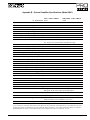
Appendix A - Professional Series Block Diagram
The block diagram shown is accurate for all the Professional Series amplifiers.
(The Model 10004 amplifier has four channels arranged in two pairs.)
Octal accessory socket
Channel A
non-inverting
Output stage
Attenuator
inverting
Preamp
ground
Amp front end
B
P
S
non-inverting
Output relay
Mode switch
Channel B
Output stage
Attenuator
inverting
ground
Preamp
Amp front end
Appendix A
Output relay
Crest Audio Pro Series Power Amplifiers
Appendix B - General Amplifier Specifications (Model 3301)
8Ω Stereo Power
4Ω Stereo Power
2ΩStereo Power
8Ω Bridged Mono Power
4Ω Bridged Mono Power
Max RMS Output Voltage (each channel)
Peak Output Voltage (each channel)
Frequency Response (+0 / -0.3dB, 1W/8Ω)
Power Bandwidth (rated power at 4Ω, 1% THD+N)
Protection Circuitry
THD+N (rated power at 4Ω, 1kHz)
SMPTE IMD (rated power at 8Ω, 60Hz & 7kHz)
Damping Factor (10-400Hz at 8Ω)
Input CMRR (1kHz)
Input Sensitivity (rated power at 4Ω )
Voltage Gain
Input Impedance (balanced)
Hum and Noise (“A” weighted, full power, 4Ω)
Crosstalk (“A” weighted, full power, 4Ω)
Class
Input Connectors (per channel)
Output Connectors (per channel)
Filter Storage
Standard Power Supply (USA)
Idle Current Draw (120V)
1/8 Power Curr. Draw (typical music, 120V/4Ω)
1/3 Power Curr. Draw (continuous music, 120V/4Ω)
Max Curr. Draw (circuit breaker rating, 120V/4Ω)
Thermal Emissions (1/8 Power, 4Ω)
Thermal Emissions (1/3 Power, 4Ω)
Cooling
Controls
LED Indicators (per channel)
Construction
Dimensions (Height x Width x Depth)
Gross Weight, Net Weight
Warranty
1kHz, <0.025% THD+N
20Hz-20kHz, <0.1% THD+N
240W
220W
380W
330W
425W
400W
725W
660W
830W
800W
49V
69V
20 Hz-20 kHz, -3dB @ 53kHz
20 Hz-20 kHz, +0/-0.2dB
Clip Limit, IGM, AutoRamp, High Temp, short-circuit,
DC voltage, turn-on/off transient, sub/ultrasonic input.
<0.025%
<0.1%
400:1
>60 dB
0.908V RMS
X40
>20kΩ
> -100 dB
> -60dB
AB
Female XLR (pin 3+), Octal Socket
5-way output binding posts
29,200 µF
120V, 60Hz
1.0A
6.25A
9.0A
11.0A
2235 BTU/hr
2821 BTU/hr
Rear to front tunnel heatsink, variable speed DC fan
Front panel: 2 attenuators, circuit breaker/power switch;
Rear panel: mode switch, signal ground lift jumper.
Clip/Limit, Signal, Temp/DC, Active
16 ga. single piece steel chassis, .187" (5mm) alum. front panel
3.5"x19"x15" (16" to rear ears)
89mm x 483mm x 381mm (406mm to rear ears)
47.0 lbs (21.34 kg.), 42.0 lbs (19.07 kg.)
5 years, parts and labor†
† USA, Canada, U.K., and many other countries. Power figures are watts per channel, both channels driven. Crest Audio reserves the right
to make improvements in manufacturing or design which may affect specifications. Crest Audio specification literature is available in
downloadable PDF file format; visit our website at http://www.crestaudio.com. ©1997 Crest Audio Inc. 12/15/97
Crest Audio Pro Series Power Amplifiers
Appendix B
Appendix B - General Amplifier Specifications (Model 4601)
8Ω Stereo Power
4Ω Stereo Power
8Ω Bridged Mono Power
Max RMS Output Voltage (each channel)
Peak Output Voltage (each channel)
Frequency Response (+0 / -0.3dB, 1W/8Ω)
Power Bandwidth (rated power at 4Ω, 1% THD+N)
Protection Circuitry
THD+N (rated power at 4Ω, 1kHz)
SMPTE IMD (rated power at 8Ω, 60Hz & 7kHz)
Damping Factor (10-400Hz at 8Ω)
Input CMRR (1kHz)
Input Sensitivity (rated power at 4Ω )
Voltage Gain
Input Impedance (balanced)
Hum and Noise (“A” weighted, full power, 4Ω)
Crosstalk (“A” weighted, full power, 4Ω)
Class
Input Connectors (per channel)
Output Connectors (per channel)
Filter Storage
Standard Power Supply (USA)
Idle Current Draw (120V)
1/8 Power Curr. Draw (typical music, 120V/4Ω)
1/3 Power Curr. Draw (continuous music, 120V/4Ω)
Max Curr. Draw (circuit breaker rating, 120V/4Ω)
Thermal Emissions (1/8 Power, 4Ω)
Thermal Emissions (1/3 Power, 4Ω)
Cooling
Controls
LED Indicators (per channel)
Construction
Dimensions (Height x Width x Depth)
Gross Weight, Net Weight
Warranty
1kHz, <0.012% THD+N
20Hz-20kHz, <0.05% THD+N
350W
300W
485W
425W
925W
825W
59V
83.4V
20 Hz-20 kHz, -3dB @ 53kHz
20 Hz-20 kHz, +0/-0.2dB
Clip Limit, IGM, AutoRamp, High Temp, short-circuit,
DC voltage, turn-on/off transient, sub/ultrasonic input.
<0.012%
<0.1%
400:1
>60 dB
1.03V RMS
X40
>20kΩ
> -100 dB
> -60dB
AB
Female XLR (pin 3+), Octal Socket
5-way output binding posts
40,800 µF
120V, 60Hz
1.1A
7.3A
11.1A
18.0A
2576 BTU/hr
3443 BTU/hr
Rear to front tunnel heatsink, 2 variable speed DC fans
Front panel: 2 attenuators, circuit breaker/power switch;
Rear panel: mode switch, signal ground lift jumper.
Clip/Limit, Signal, Temp/DC, Active
16 ga. single piece steel chassis, .187" (5mm) alum. front panel
3.5"x19"x15" (16" to rear ears)
89mm x 483mm x 381mm (406mm to rear ears)
48.0 lbs (21.79 kg.), 43.0 lbs (19.52 kg.)
5 years, parts and labor†
† USA, Canada, U.K., and many other countries. Power figures are watts per channel, both channels driven. Crest Audio reserves the right
to make improvements in manufacturing or design which may affect specifications. Crest Audio specification literature is available in
downloadable PDF file format; visit our website at http://www.crestaudio.com. ©1997 Crest Audio Inc. 12/15/97
Appendix B
Crest Audio Pro Series Power Amplifiers
Appendix B - General Amplifier Specifications (Model 4801)
8Ω Stereo Power
4Ω Stereo Power
8Ω Bridged Mono Power
2ΩStereo Power
4Ω Bridged Mono Power
Max RMS Output Voltage (each channel)
Peak Output Voltage (each channel)
Frequency Response (+0 / -0.3dB, 1W/8Ω)
Power Bandwidth (rated power at 4Ω, 1% THD+N)
Protection Circuitry
THD+N (rated power at 4Ω, 1kHz)
SMPTE IMD (rated power at 8Ω, 60Hz & 7kHz)
Damping Factor (10-400Hz at 8Ω)
Input CMRR (1kHz)
Input Sensitivity (rated power at 4Ω )
Voltage Gain
Input Impedance (balanced)
Hum and Noise (“A” weighted, full power, 4Ω)
Crosstalk (“A” weighted, full power, 4Ω)
Class
Input Connectors (per channel)
Output Connectors (per channel)
Filter Storage
Standard Power Supply (120V)
Idle Current Draw (120V)
1/8 Power Curr. Draw (typical music, 120V/4Ω)
1/3 Power Curr. Draw (continuous music, 120V/4Ω)
Max Curr. Draw (circuit breaker rating, 120V/4Ω)
Thermal Emissions (1/8 Power, 4Ω)
Thermal Emissions (1/3 Power, 4Ω)
Cooling
Controls
LED Indicators (per channel)
Construction
Dimensions (Height x Width x Depth)
Gross Weight, Net Weight
Warranty
1kHz, <0.025% THD+N
20Hz-20kHz, <0.05% THD+N
400W
300W
575W
480W
1150W
960W
700W
600W
1300W
1200W
60V
85V
20 Hz-20 kHz, -3dB @ 53kHz
20 Hz-20 kHz, +0/-0.2dB
Clip Limit, IGM, AutoRamp, High Temp, short-circuit,
DC voltage, turn-on/off transient, sub/ultrasonic input.
<0.025%
<0.1%
400:1
>60 dB
1.1V RMS
X40
>20kΩ
> -100 dB
> -60dB
H
Female XLR (pin 3+), Octal Socket
5-way output binding posts
80,000 µF
120V, 60Hz
1.1A
5.6A
11.46
18.0A
1803 BTU/hr
3385 BTU/hr
Rear to front tunnel heatsink, variable speed DC fan
Front panel: 2 attenuators, circuit breaker/power switch;
Rear panel: mode switch, signal ground lift jumper.
Clip/Limit, Signal, Temp/DC, Active
16 ga. single piece steel chassis, .187" (5mm) alum. front panel
3.5"x19"x15" (16" to rear ears)
89mm x 483mm x 381mm (406mm to rear ears)
54.0 lbs (24.52 kg.), 49.0 lbs (22.25 kg.)
5 years, parts and labor†
† USA, Canada, U.K., and many other countries. Power figures are watts per channel, both channels driven. Crest Audio reserves the right
to make improvements in manufacturing or design which may affect specifications. Crest Audio specification literature is available in
downloadable PDF file format; visit our website at http://www.crestaudio.com. ©1997 Crest Audio Inc. 12/15/97
Crest Audio Pro Series Power Amplifiers
Appendix B
Appendix B - General Amplifier Specifications (Model 6001)
8Ω Stereo Power
4Ω Stereo Power
2ΩStereo Power
8Ω Bridged Mono Power
4Ω Bridged Mono Power
Max RMS Output Voltage (each channel)
Peak Output Voltage (each channel)
Frequency Response (+0 / -0.3dB, 1W/8Ω)
Power Bandwidth (rated power at 4Ω, 1% THD+N)
Protection Circuitry
THD+N (rated power at 4Ω, 1kHz)
SMPTE IMD (rated power at 8Ω, 60Hz & 7kHz)
Damping Factor (10-400Hz at 8Ω)
Input CMRR (1kHz)
Input Sensitivity (rated power at 4Ω )
Voltage Gain
Input Impedance (balanced)
Hum and Noise (“A” weighted, full power, 4Ω)
Crosstalk (“A” weighted, full power, 4Ω)
Class
Input Connectors (per channel)
Output Connectors (per channel)
Filter Storage
Standard Power Supply (USA)
Idle Current Draw (120V)
1/8 Power Curr. Draw (typical music, 120V/4Ω)
1/3 Power Curr. Draw (continuous music, 120V/4Ω)
Max Curr. Draw (circuit breaker rating, 120V/4Ω)
Thermal Emissions (1/8 Power, 4Ω)
Thermal Emissions (1/3 Power, 4Ω)
Cooling
Controls
LED Indicators (per channel)
Construction
Dimensions (Height x Width x Depth)
Gross Weight, Net Weight
Warranty
1kHz, <0.025% THD+N
20Hz-20kHz, <0.05% THD+N
430W
400W
700W
600W
800W
720W
1320W
1200W
1500W
1440W
70V
99V
20 Hz-20 kHz, -3dB @ 53kHz
20 Hz-20 kHz, +0/-0.2dB
Clip Limit, IGM, AutoRamp, High Temp, short-circuit,
DC voltage, turn-on/off transient, sub/ultrasonic input.
<0.025%
<0.1%
400:1
>60 dB
1.2V RMS
X40
>20kΩ
> -100 dB
> -60dB
H
Female XLR (pin 3+), Octal Socket
5-way output binding posts
120,000 µF
120V, 60Hz
1.1A
5.96A
13.26A
21A
1844 BTU/hr
3838 BTU/hr
Rear to front tunnel heatsink, variable speed DC fan
Front panel: 2 attenuators, circuit breaker/power switch;
Rear panel: mode switch, signal ground lift jumper.
Clip/Limit, Signal, Temp/DC, Active
16 ga. single piece steel chassis, .187" (5mm) alum. front panel
3.5"x19"x15" (16" to rear ears)
89mm x 483mm x 381mm (406mm to rear ears)
56.0 lbs. (25.42 kg.), 51.0 lbs. (23.10 kg.)
5 years, parts and labor†
† USA, Canada, U.K., and many other countries. Power figures are watts per channel, both channels driven. Crest Audio reserves the
right to make improvements in manufacturing or design which may affect specifications. Crest Audio specification literature is available
in downloadable PDF file format; visit our website at http://www.crestaudio.com. ©1997 Crest Audio Inc. 12/15/97
Appendix B
Crest Audio Pro Series Power Amplifiers
Appendix B - General Amplifier Specifications (Model 7001)
8Ω Stereo Power
4Ω Stereo Power
8Ω Bridged Mono Power
2ΩStereo Power
4Ω Bridged Mono Power
Max RMS Output Voltage (each channel)
Peak Output Voltage (each channel)
Frequency Response (+0 / -0.3dB, 1W/8Ω)
Power Bandwidth (rated power at 4Ω, 1% THD+N)
Protection Circuitry
THD+N (rated power at 4Ω, 1kHz)
SMPTE IMD (rated power at 8Ω, 60Hz & 7kHz)
Damping Factor (10-400Hz at 8Ω)
Input CMRR (1kHz)
Input Sensitivity (rated power at 4Ω )
Voltage Gain
Input Impedance (balanced/unbalanced)
Hum and Noise (“A” weighted, full power, 4Ω)
Crosstalk (“A” weighted, full power, 4Ω)
Class
Input Connectors (per channel)
Output Connectors (per channel)
Filter Storage
Standard Power Supply (USA)
Idle Current Draw (120V)
1/8 Power Curr. Draw (typical music, 120V/4Ω)
1/3 Power Curr. Draw (continuous music, 120V/4Ω)
Max Curr. Draw (circuit breaker rating, 120V/4Ω)
Thermal Emissions (1/8 Power, 4Ω)
Thermal Emissions (1/3 Power, 4Ω)
Cooling
Controls
LED Indicators (per channel)
Construction
Dimensions (Height x Width x Depth)
Gross Weight, Net Weight
Warranty
1kHz, <0.02% THD+N
20Hz-20kHz, <0.05% THD+N
560W
550W
810W
715W
1650W
1510W
850W
850W
1700W
1600W
83V
117V
20 Hz-20 kHz, -3dB @ 53kHz
20 Hz-20 kHz, +0/-0.2dB
Clip Limit, IGM, AutoRamp, High Temp, short-circuit,
DC voltage, turn-on/off transient, sub/ultrasonic input.
<0.02%
<0.1%
400:1
>60 dB
1.4V RMS
X40
>20kΩ/10kΩ
> -100 dB
> -60dB
H
Female XLR (pin 3+), Octal Socket
5-way output binding posts
80,000 µF
120V, 60Hz
1.4A
7.8A
15.5A
21.0A
2503 BTU/hr
4505 BTU/hr
Rear to front tunnel heatsink, 2 variable speed DC fans
Front panel: 2 attenuators, circuit breaker/power switch;
Rear panel: mode switch, signal ground lift jumper.
Clip/Limit, Signal, Temp/DC, Active
16 ga. single piece steel chassis, .187" (5mm) alum. front panel
3.5"x19"x15" (16" to rear ears)
89mm x 483mm x 381mm (406mm to rear ears)
57 lbs. (25.88 kg.), 52 lbs. (23.60 kg.)
5 years, parts and labor†
† USA, Canada, U.K., and many other countries. Power figures are watts per channel, both channels driven. Crest Audio reserves the right
to make improvements in manufacturing or design which may affect specifications. Crest Audio specification literature is available in
downloadable PDF file format; visit our website at http://www.crestaudio.com. ©1997 Crest Audio Inc. 12/15/97
Crest Audio Pro Series Power Amplifiers
Appendix B
Appendix B - General Amplifier Specifications (Model 7301)
Lows @ 100Hz, <0.1% THD+N
Both Channels @ 4Ω
Lows @ 2Ω, Highs @ 4Ω
Lows @ 4Ω, Highs @ 8Ω
Lows @ 8Ω, Highs @ 16Ω
Max RMS Output Voltage (each channel)
Peak Output Voltage (each channel)
Frequency Response (+0 / -0.3dB, 1W/8Ω)
Power Bandwidth (rated power at 4Ω, 1% THD+N)
Protection Circuitry
THD+N (rated power at 4Ω, 1kHz)
Damping Factor (10-400Hz at 8Ω)
Input CMRR (1kHz)
Input Sensitivity (8Ω)
Voltage Gain
Input Impedance (balanced)
Hum and Noise (“A” weighted, full power, 4Ω)
Crosstalk (“A” weighted, full power, 4Ω)
Class
Input Connectors (per channel)
Output Connectors (per channel)
Filter Storage
Standard Power Supply (USA)
Idle Current Draw (120V)
1/8 Power Curr. Draw (typical music, 120V/4Ω)
1/3 Power Curr. Draw (continuous music, 120V/4Ω)
Max Curr. Draw (circuit breaker rating, 120V/4Ω)
Thermal Emissions (1/8 Power, 4Ω)
Thermal Emissions (1/3 Power, 4Ω)
Cooling
Controls
LED Indicators (per channel)
Construction
Dimensions (Height x Width x Depth)
Gross Weight, Net Weight
Warranty
Highs @ 1kHz, <0.05% THD+N
940W
240W
990W
220W
940W
125W
670W
95W
83V(Low Ch.) 49V(High Ch.)
117V(Low Ch.) 69V(High Ch.)
20 Hz-20 kHz, -3dB @ 53kHz
20 Hz-20 kHz, +0/-0.2dB
Clip Limit, IGM, AutoRamp, High Temp, short-circuit,
DC voltage, turn-on/off transient, sub/ultrasonic input.
<0.02% @ 800W (Low Ch.); 200W ( High Ch.)
400:1
>60 dB
1.53V RMS (Low ) .79V RMS (High )
X40
>20kΩ
> -100 dB
> -60dB
H (Low Channel); AB (High Channel)
Female XLR (pin 3+), Octal Socket
5-way output binding posts
80,000 µF
120V, 60Hz
1.2A
7.0A
12.25A
21.0A
2300 BTU/hr
3700 BTU/hr
Rear to front tunnel heatsink, 2 variable speed DC fans
Front panel: 2 attenuators, circuit breaker/power switch;
Rear panel: signal ground lift jumper.
Clip/Limit, Signal, Temp/DC, Active
16 ga. steel chassis, 0.187" (5mm) aluminum front panel
3.5"x19"x15" (16" to rear ears)
89mm x 483mm x 381mm (406mm to rear ears)
57 lbs. (25.88 kg.), 52 lbs. (23.60 kg.)
5 years, parts and labor†
† USA, Canada, U.K., and many other countries. Power figures are watts per channel, both channels driven. Crest Audio reserves the right
to make improvements in manufacturing or design which may affect specifications. Crest Audio specification literature is available in
downloadable PDF file format; visit our website at http://www.crestaudio.com. ©1997 Crest Audio Inc. 12/15/97
Appendix B
Crest Audio Pro Series Power Amplifiers
Appendix B - General Amplifier Specifications (Model 8001)
8Ω Stereo Power
4Ω Stereo Power
8Ω Bridged Mono Power
2ΩStereo Power
4Ω Bridged Mono Power
Max RMS Output Voltage (each channel)
Peak Output Voltage (each channel)
Frequency Response (+0 / -0.3dB, 1W/8Ω)
Power Bandwidth (rated power at 4Ω, 1% THD+N)
Protection Circuitry
THD+N (rated power at 4Ω, 1kHz)
SMPTE IMD (rated power at 8Ω, 60Hz & 7kHz)
Damping Factor (10-400Hz at 8Ω)
Input CMRR (1kHz)
Input Sensitivity (rated power at 4Ω )
Voltage Gain
Input Impedance (balanced)
Hum and Noise (“A” weighted, full power, 4Ω)
Crosstalk (“A” weighted, full power, 4Ω)
Class
Input Connectors (per channel)
Output Connectors (per channel)
Filter Storage
Standard Power Supply (USA)
Idle Current Draw (120V)
1/8 Power Curr. Draw (typical music, 120V/4Ω)
1/3 Power Curr. Draw (continuous music, 120V/4Ω)
Max Curr. Draw (circuit breaker rating, 120V/4Ω)
Thermal Emissions (1/8 Power, 4Ω)
Thermal Emissions (1/3 Power, 4Ω)
Cooling
Controls
LED Indicators (per channel)
Construction
Dimensions (Height x Width x Depth)
Gross Weight, Net Weight
Warranty
1kHz, <0.025% THD+N
20Hz-20kHz, <0.1% THD+N
750W
720W
1225W
1200W
2450W
2250W
1400W
1400W
2800W
2800W
91V
129V
20 Hz-20 kHz, -3dB @ 53kHz
20 Hz-20 kHz, +0/-0.2dB
Clip Limit, IGM, AutoRamp, High Temp, short-circuit,
DC voltage, turn-on/off transient, sub/ultrasonic input.
<0.025%
<0.1%
400:1
>60 dB
1.75V RMS
X40
>20kΩ
> -100 dB
> -60dB
H
Female XLR (pin 3+), Octal Socket
2 pair 5-way output binding posts
70,000 µF
120V, 60Hz
1.6A
10.8A
21.8A
37.5A
3380 BTU/hr
6140 BTU/hr
Rear to front tunnel heatsink, 105 CFM AC fan, 2-speed optional.
Front panel: 2 attenuators, circuit breaker/power switch;
Rear panel: mode switch, signal ground lift jumper.
Clip/Limit, Signal, Temp/DC, Active
14 ga. steel chassis, 0.25" (6mm) aluminum front panel
5.25"x19"x15" (16" to rear ears)
133mm x 483mm x 381mm (406mm to rear ears)
85 lbs. (38.6 kg.), 80 lbs. (36.0 kg.)
5 years, parts and labor†
† USA, Canada, U.K., and many other countries. Power figures are watts per channel, both channels driven. Crest Audio reserves the right to
make improvements in manufacturing or design which may affect specifications. Crest Audio specification literature is available in downloadable PDF file format; visit our website at http://www.crestaudio.com. ©1997 Crest Audio Inc. 12/15/97
Crest Audio Pro Series Power Amplifiers
Appendix B
Appendix B - General Amplifier Specifications (Model 9001)
8Ω Stereo Power
4Ω Stereo Power
8Ω Bridged Mono Power
2ΩStereo Power
4Ω Bridged Mono Power
Max RMS Output Voltage (each channel)
Peak Output Voltage (each channel)
Frequency Response (+0 / -0.3dB, 1W/8Ω)
Power Bandwidth (rated power at 4Ω, 1% THD+N)
Protection Circuitry
THD+N (rated power at 4Ω, 1kHz)
SMPTE IMD (rated power at 8Ω, 60Hz & 7kHz)
Damping Factor (10-400Hz at 8Ω)
Input CMRR (1kHz)
Input Sensitivity (rated power at 4Ω )
Voltage Gain
Input Impedance (balanced)
Hum and Noise (“A” weighted, full power, 4Ω)
Crosstalk (“A” weighted, full power, 4Ω)
Class
Input Connectors (per channel)
Output Connectors (per channel)
Filter Storage
Standard Power Supply (USA)
Idle Current Draw (120V)
1/8 Power Curr. Draw (typical music, 120V/4Ω)
1/3 Power Curr. Draw (continuous music, 120V/4Ω)
Max Curr. Draw (circuit breaker rating, 120V/4Ω)
Thermal Emissions (1/8 Power, 4Ω)
Thermal Emissions (1/3 Power, 4Ω)
Cooling
Controls
LED Indicators (per channel)
Construction
Dimensions (Height x Width x Depth)
Gross Weight, Net Weight
Warranty
1kHz, <0.02% THD+N
20Hz-20kHz, <0.1% THD+N
1200W
1100W
2200W
2050W
4400W
4100W
3300W
3000W
6600W
6000W
114V
161V
20 Hz-20 kHz, -3dB @ 53kHz
20 Hz-20 kHz, +0/-0.2dB
Clip Limit, IGM, AutoRamp, High Temp, short-circuit,
DC voltage, turn-on/off transient, sub/ultrasonic input.
<0.02%
0.05%
200:1
>60 dB
2.26V RMS
X40
>20kΩ
> -100 dB
> -60dB
H
Female XLR Input (pin 3+), Octal Socket.
Single screw solderless copper output lugs.
46,000 µF
120V, 60Hz
2.0A
16.2A
30.0A
65.0A
3850 BTU/hr
7700 BTU/hr
Rear to front tunnel heatsink, variable speed DC fan, 140 CFM max.
Front panel: 2 attenuators, circuit breaker/power switch;
Rear panel: mode switch, signal ground lift jumper.
Clip/Limit, Signal, Temp/DC, Active
12 ga. steel chassis, 0.187" (5mm) aluminum front panel
5 1/4" x 19" x 19.5", 133mm x 483mm x 496mm
115 lbs (52.21 kg.), 110 lbs (49.94 kg.)
5 years, parts and labor†
† USA, Canada, U.K., and many other countries. Power figures are watts per channel, both channels driven. Crest Audio reserves the
right to make improvements in manufacturing or design which may affect specifications. Crest Audio specification literature is available
in downloadable PDF file format; visit our website at http://www.crestaudio.com. ©1997 Crest Audio Inc. 12/15/97
Appendix B
Crest Audio Pro Series Power Amplifiers
Appendix B - General Amplifier Specifications (Model 10001)
2Ω Stereo Power
1Ω Stereo Power
4Ω Bridged Mono Power
2Ω Bridged Mono Power
Max RMS Output Voltage (each channel)
Peak Output Voltage (each channel)
Frequency Response (+0 / -0.3dB, 1W/8Ω)
Power Bandwidth (rated power at 4Ω, 1% THD+N)
Protection Circuitry
THD+N (rated power at 4Ω, 1kHz)
SMPTE IMD (rated power at 8Ω, 60Hz & 7kHz)
Damping Factor (10-400Hz at 8Ω)
Input CMRR (1kHz)
Input Sensitivity (rated power at 4Ω )
Voltage Gain
Input Impedance (balanced)
Hum and Noise (“A” weighted, full power, 4Ω)
Crosstalk (“A” weighted, full power, 4Ω)
Class
Input Connectors (per channel)
Output Connectors (per channel)
Filter Storage
Power Supply (factory configured)
Idle Current Draw (120V)
1/8 Power Curr. Draw (typical music, 120V/4Ω)
1/3 Power Curr. Draw (continuous music, 120V/4Ω)
Max Curr. Draw (circuit breaker rating, 120V/4Ω)
Thermal Emissions (1/8 Power, 4Ω)
Thermal Emissions (1/3 Power, 4Ω)
Cooling
Controls
LED Indicators (per channel)
Construction
Dimensions (Height x Width x Depth)
Gross Weight, Net Weight
Warranty
20Hz-20kHz, <0.1% THD+N Typical Music Prog. Material
3500W
5000W
5000W
7500W
7000W
10,000W
10,000W
15,000W
105V
150V
20 Hz-20 kHz, -3dB @ 53kHz
20 Hz-20 kHz, +0/-0.2 dB
Clip Limit, IGM, AutoRamp, High Temp, short-circuit,
DC voltage, turn-on/off transient, sub/ultrasonic input.
<0.02%
0.05%
580:1
>60 dB
2.24V RMS
X40
>20kΩ
> -100 dB
> -60dB
H
Female XLR Input (pin 3+), Octal Socket
Single screw solderless copper output lugs.
29,200 µF
100V–240V, 50–60Hz
2.0A per line cord
13.0A per line cord
25.0A per line cord
35.6A per line cord
4450 BTU/hr
7908 BTU/hr
Rear to front tunnel, variable speed DC fan, 235 CFM max.
Front panel: 2 attenuators, circuit breaker/power switch; Rear
panel: mode switch, signal ground lift jumper.
Clip/Limit, Signal, Temp/DC, Active
12 ga. steel chassis, 0.075" (1.9mm) aluminum front panel
7" x 19" x 20.5" (19.5" to end of rear ears),
178mm x 483mm x 521mm (496mm to back of rear ears)
145 lbs (65.83 kg.), 137 lbs (62.20 kg.)
5 years, parts and labor†
† USA, Canada, U.K., and many other countries. Power figures are watts per channel, both channels driven. Crest Audio reserves the right
to make improvements in manufacturing or design which may affect specifications. Crest Audio specification literature is available in
downloadable PDF file format; visit our website at http://www.crestaudio.com. ©1997 Crest Audio Inc. 12/15/97
Crest Audio Pro Series Power Amplifiers
Appendix B
Appendix B - General Amplifier Specifications (Model 10004)
8Ω Stereo Power (x4 ch.)
4Ω Stereo Power (x4 ch.)
8Ω Bridged Mono Power (x2 ch.)
2ΩStereo Power (x4 ch.)
4Ω Bridged Mono Power (x2 ch.)
Max RMS Output Voltage (each channel)
Peak Output Voltage (each channel)
Frequency Response (+0 / -0.3dB, 1W/8Ω)
Power Bandwidth (rated power at 4Ω, 1% THD+N)
Protection Circuitry
THD+N (rated power at 4Ω, 1kHz)
SMPTE IMD (rated power at 8Ω, 60Hz & 7kHz)
Damping Factor (10-400Hz at 8Ω)
Input CMRR (1kHz)
Input Sensitivity (rated power at 4Ω )
Voltage Gain
Input Impedance (balanced)
Hum and Noise (“A” weighted, full power, 4Ω)
Crosstalk (“A” weighted, full power, 4Ω)
Class
Input Connectors (per channel)
Output Connectors (per channel)
Filter Storage
Power Supply (factory configured)
Idle Current Draw (120V)
1/8 Power Curr. Draw (typical music, 120V/4Ω)
1/3 Power Curr. Draw (continuous music, 120V/4Ω)
Max Curr. Draw (circuit breaker rating, 120V/4Ω)
Thermal Emissions (1/8 Power, 4Ω)
Thermal Emissions (1/3 Power, 4Ω)
Cooling
Controls
LED Indicators (per channel)
Construction
Dimensions (Height x Width x Depth)
Gross Weight, Net Weight
Warranty
1kHz, <0.02% THD+N
20Hz-20kHz, <0.1% THD+N
750W
720W
1225W
1200W
2450W
2400W
1400W
1400W
2800W
2800W
91V
137V
20 Hz-20 kHz, -3dB @ 53kHz
20 Hz-20 kHz, +0/-0.2dB
Clip Limit, IGM, AutoRamp, High Temp, short-circuit,
DC voltage, turn-on/off transient, sub/ultrasonic input.
<0.02%
0.06%
600:1
>60 dB
1.7V RMS
X40
>20kΩ
> -100 dB
> -60dB
H
Female XLR (pin 3+), Octal Socket
5-way output binding posts
168,000 µF per channel
100V–240V, 50–60Hz
1.6A per line cord
10.8A per line cord
21.8A per line cord
35.6A per line cord
3380 BTU/hr
6140 BTU/hr
Rear to front tunnel, 2 speed DC fan, 235 CFM max
Front panel: 4 attenuators, 2 circuit breaker /power switches;
Rear panel: 2 mode switches, signal ground lift jumper
Clip/Limit, Signal, Temp/DC, Active
12 ga. steel chassis, .093" (2.5mm) aluminum front panel
7" x 19" x 20.5" (19.5" to end of rear ears);
178mm x 483mm x 521mm (496mm to back of rear ears)
145 lbs (65.83 kg.), 137 lbs (62.20 kg.)
5 years, parts and labor†
† USA, Canada, U.K., and many other countries. Power figures are watts per channel, both channels driven. Crest Audio reserves the
right to make improvements in manufacturing or design which may affect specifications. Crest Audio specification literature is available in downloadable PDF file format; visit our website at http://www.crestaudio.com. ©1997 Crest Audio Inc. 12/15/97
Appendix B
Crest Audio Pro Series Power Amplifiers
Appendix C - Wire Gauge Charts
Stranded Cable Lgth.
(ft.)
Wire Gauge (AWG)
Power Loss
(8 ohm load)
Power Loss
(4 ohm load)
Power Loss
(2 ohm load)
5
18
16
14
12
10
0.81%
0.51
0.32
0.20
0.128
1.61%
1.02
0.64
0.40
0.25
3.2%
2.0
1.28
0.80
0.51
10
18
16
14
12
10
1.61%
1.02
0.64
0.40
0.25
3.2%
2.0
1.28
0.80
0.51
6.2%
4.0
2.5
1.60
1.01
40
18
16
14
12
10
8
6.2%
4.0
2.5
1.60
1.01
0.60
11.9%
7.7
5.0
3.2
2.0
1.20
22%
14.6
9.6
6.2
4.0
2.4
18
16
14
12
10
8
11.9%
7.7
5.0
3.2
2.0
1.20
22%
14.6
9.6
6.2
4.0
2.4
37%
26
17.8
11.8
7.7
4.7
Stranded Cable Lgth.
(m)
Wire Gauge (mm2)
Power Loss
(8 ohm load)
Power Loss
(4 ohm load)
Power Loss
(2 ohm load)
2
0.3
0.5
0.75
1.5
2.5
4
2.9%
1.74
1.16
0.58
0.35
0.22
5.6%
3.4
2.3
1.16
0.70
0.44
10.8%
6.7
4.5
2.3
1.39
0.87
5
0.5
0.75
1.5
2.5
4
6
4.3%
2.9
1.45
0.87
0.55
0.37
8.2%
5.6
2.9
1.74
1.09
0.73
15.5%
10.8
5.6
3.4
2.2
1.45
10
0.5
0.75
1.5
2.5
4
6
8.24%
5.6
2.9
1.74
1.09
0.73
15.5%
10.8
5.6
2.9
1.74
1.09
28%
19.9
10.8
6.7
4.3
2.9
30
0.75
1.5
2.5
4
6
10
15.5%
8.2
5.1
3.2
2.2
1.31
25%
15.5
9.8
6.3
4.3
2.6
45%
28
18.2
12.0
8.2
5.1
80
Crest Audio Pro Series Power Amplifiers
Appendix C
Appendix D
Meyer-Compatible Power Amplifiers
The Crest Audio Models MA5850, MA9130, and MA7120 Professional power amplifiers are specifically designed in close cooperation with Meyer Sound Laboratories to meet the needs of the European Meyer Sound loudspeaker user. This manual describes all of
the important aspects of amplifier installation, mounting, connection and operation. Additional information pertaining to these power
amplifiers is provided in this appendix.
MA5850 - Based on the Crest Audio Professional Series 4801 power amplifier, the MA5850 contains custom circuitry to limit output
to 58V RMS per channel, effectively preventing driver over-excursion on the models for which it is intended. As the power supply of
the MA5850 is capable of much greater output, this design also reduces possible damage from clipped waveforms. The MA5850 is
specifically designed as a Meyer Type 1 power amplifier. The gain setting is 23 dB at Meyer’s recommendation.
MA9130 - The MA9130 is based on the Crest Audio Professional Series 8001 power amplifier, using a custom designed, low noise
two speed fan and custom circuitry for operation as a Meyer Type 2 Power Amplifier. The MA9130 gain setting is also 23 dB.
MA7120 - The MA7120, based on the Crest Audio Professional Series 6001 and 7001 power amplifiers, is intended for bridged mode
operation, with a voltage gain of 6.3 (+16 dB). It has been specifically designed to meet the high power requirements of a Meyer Type
3 power amplifier.
Warranty applicable in USA, Canada, U.K., and many other countries. Power figures are watts per channel, both channels driven. Crest Audio reserves the right to make improvements in manufacturing or design which may
affect specifications. Crest Audio specification literature is available in downloadable PDF file format; visit our website at http://www/crestaudio.com. ©1996 Crest Audio Inc.
MA5850
8Ω Stereo Power
4Ω Stereo Power
8Ω Bridged Mono Power
Max RMS Output Voltage (each channel)
Peak Output Voltage (each channel)
Frequency Response (+0 / -0.3dB, 1W/8Ω)
Power Bandwidth (rated power at 4Ω, 1% THD+N)
Protection Circuitry
THD+N (rated power at 8Ω, 1kHz)
SMPTE IMD (rated power at 8Ω, 60Hz & 7kHz)
Damping Factor (10-400Hz at 8Ω)
Input CMRR (1kHz)
Input Sensitivity (rated power at 4Ω )
Voltage Gain
Input Impedance (balanced)
Hum and Noise (“A” weighted, full power, 4Ω)
Crosstalk (“A” weighted, full power, 4Ω)
Class
Input Connectors (per channel)
Output Connectors (per channel)
Filter Storage
Power Supply (factory configured)
Idle Current Draw (240V)
1/8 Power Curr. Draw (typical music, 120V/4Ω)
1/3 Power Curr. Draw (continuous music, 120V/4Ω)
Max Curr. Draw (circuit breaker rating, 120V/4Ω)
Thermal Emissions (1/8 Power, 4Ω)
Thermal Emissions (1/3 Power, 4Ω)
Cooling
Controls
LED Indicators (per channel)
Construction
Dimensions (Height x Width x Depth)
Gross Weight, Net Weight
Warranty
1kHz, <0.05% THD+N
20Hz-20kHz, <0.1% THD+N
400W
300W
575W
480W
1150W
960W
58V
82V
20 Hz-20 kHz, -3dB @ 53kHz
20 Hz-20 kHz, +0/-0.2dB
Clip Limit, IGM, AutoRamp, High Temp, short-circuit,
DC voltage, turn-on/off transient, sub/ultrasonic input.
<0.05%
<0.015%
400:1
>60 dB
3.5V RMS
X14 (+23dB)
>20kΩ
>-100 dB
>-60dB
H
Female XLR (pin 3+), Octal Socket
5-way output binding posts
80,000 µF
100V–240V, 50–60Hz
.55A
2.8A
5.75A
10.0A
1803 BTU/hr
3385 BTU/hr
Rear to front tunnel heatsink, variable speed DC fan
Front panel: 2 attenuators, circuit breaker/power switch;
Rear panel: mode switch, signal ground lift jumper.
Clip/Limit, Signal, Temp/DC, Active
16 ga. single piece steel chassis, .187" (5mm) alum. front panel
3.5"x19"x15" (16" to rear ears)
89mm x 483mm x 381mm (406mm to rear ears)
54.0 lbs (24.52 kg.), 49.0 lbs (22.25 kg.)
5 years, parts and labor†
† USA, Canada, U.K., and many other countries. Power figures are watts per channel, both channels driven. Crest Audio reserves the right to
make improvements in manufacturing or design which may affect specifications. Crest Audio specification literature is available in down-
Appendix D
Crest Audio Pro Series Power Amplifiers
MA7120
8Ω Bridged Mono Power
4Ω Bridged Mono Power
Max RMS Output Voltage (bridged)
Peak Output Voltage (bridged)
Frequency Response (+0 / -0.3dB, 1W/8Ω)
Power Bandwidth (rated power at 4Ω, 1% THD+N)
Protection Circuitry
THD+N (rated power, 1kHz)
SMPTE IMD (rated power at 8Ω, 60Hz & 7kHz)
Damping Factor (10-400Hz at 8Ω)
Input CMRR (1kHz)
Input Sensitivity (rated power at 4Ω bridged )
Voltage Gain
Input Impedance (balanced)
Hum and Noise (“A” weighted, full power, 4Ω)
Crosstalk (“A” weighted, full power, 4Ω)
Class
Input Connectors (per channel)
Output Connectors (per channel)
Filter Storage
Power Supply (factory configured)
Idle Current Draw (120V)
1/8 Power Curr. Draw (typical music, 120V/4Ω)
1/3 Power Curr. Draw (continuous music, 120V/4Ω)
Max Curr. Draw (circuit breaker rating, 120V/4Ω)
Thermal Emissions (1/8 Power, 4Ω)
Thermal Emissions (1/3 Power, 4Ω)
Cooling
Controls
LED Indicators (per channel)
Construction
Dimensions (Height x Width x Depth)
Gross Weight, Net Weight
Warranty
1kHz, <0.03% THD+N
20Hz-20kHz, <0.1% THD+N
1150W
975W
1200W
1100W
140V
198V
20 Hz-20 kHz, -3dB @ 53kHz
20 Hz-20 kHz, +0/-0.2dB
Clip Limit, IGM, AutoRamp, High Temp, short-circuit,
DC voltage, turn-on/off transient, sub/ultrasonic input.
<0.03%
<0.5%
400:1
>60 dB
10.5V RMS for 1100W at 4Ω bridged
X6.3 (+16dB) bridged
>20kΩ
>-100 dB
>-60dB
H
Female XLR (pin 3+), Octal Socket
5-way output binding posts
120,000 µF
100V–240V, 50–60Hz
0.7A
3.9A
7.75A
15.0A
2503 BTU/hr
4505 BTU/hr
Rear to front tunnel heatsink, 2 variable speed DC fans
Front panel: 2 attenuators, circuit breaker/power switch;
Rear panel: mode switch, signal ground lift jumper.
Clip/Limit, Signal, Temp/DC, Active
16 ga. single piece steel chassis, .187" (5mm) alum. front panel
3.5"x19"x15" (16" to rear ears)
89mm x 483mm x 381mm (406mm to rear ears)
57 lbs. (25.88 kg.), 52 lbs. (23.60 kg.)
5 years, parts and labor†
† USA, Canada, U.K., and many other countries. Power figures are watts per channel, both channels driven. Crest Audio reserves the right
make improvements in manufacturing or design which may affect specifications Crest Audio specification literature is available in dow
MA9130
8Ω Stereo Power
4Ω Stereo Power
8Ω Bridged Mono Power
2ΩStereo Power
4Ω Bridged Mono Power
Max RMS Output Voltage (each channel)
Peak Output Voltage (each channel)
Frequency Response (+0 / -0.3dB, 1W/8Ω)
Power Bandwidth (rated power at 4Ω, 1% THD+N)
Protection Circuitry
THD+N (rated power at 4Ω, 1kHz)
SMPTE IMD (rated power at 8Ω, 60Hz & 7kHz)
Damping Factor (10-400Hz at 8Ω)
Input CMRR (1kHz)
Input Sensitivity (rated power at 4Ω )
Voltage Gain
Input Impedance (balanced)
Hum and Noise (“A” weighted, full power, 4Ω)
Crosstalk (“A” weighted, full power, 4Ω)
Class
Input Connectors (per channel)
Output Connectors (per channel)
Filter Storage
Power Supply (factory configured)
Idle Current Draw (240V)
1/8 Power Curr. Draw (typical music, 240V/4Ω)
1/3 Power Curr. Draw (continuous music, 240V/4Ω)
Max Curr. Draw (circuit breaker rating, 240V/4Ω)
Thermal Emissions (1/8 Power, 4Ω)
Thermal Emissions (1/3 Power, 4Ω)
Cooling
Controls
LED Indicators (per channel)
Construction
Dimensions (Height x Width x Depth)
Gross Weight, Net Weight
Warranty
1kHz, <0.025% THD+N
20Hz-20kHz, <0.1% THD+N
750W
720W
1225W
1200W
2450W
2250W
1400W
1400W
2800W
2800W
91V
129V
20 Hz-20 kHz, -3dB @ 53kHz
20 Hz-20 kHz, +0/-0.2dB
Clip Limit, IGM, AutoRamp, High Temp, short-circuit, DC voltage, turn-on/off transient, sub/ultrasonic input.
<0.025%
<0.1%
400:1
>60 dB
1.75V RMS
X14 (+23 dB)
>20kΩ
> -100 dB
> -60dB
H
Female XLR (pin 3+), Octal Socket
2 pair 5-way output binding posts
70,000 µF
100V–240V, 50–60Hz
0.8A
5.4A
10.9A
19.0A
3380 BTU/hr
6140 BTU/hr
Rear to front tunnel heatsink, low-noise 2-speed fan
Front panel: 2 attenuators, circuit breaker/power switch;
Rear panel: mode switch, signal ground lift jumper.
Clip/Limit, Signal, Temp/DC, Active
14 ga. steel chassis, 0.25" (6mm) aluminum front panel
5.25"x19"x15" (16" to rear ears)
133mm x 483mm x 381mm (406mm to rear ears)
85 lbs. (38.6 kg.), 80 lbs. (36.0 kg.)
5 years, parts and labor†
† USA, Canada, U.K., and many other countries. Power figures are watts per channel, both channels driven. Crest Audio reserves the right
k i
t i
f t i
d i
hi h
ff t
ifi ti
C t A di
ifi ti lit t
i
il bl i d
Crest Audio Pro Series Power Amplifiers
Appendix D
Crest Audio Inc.
100 Eisenhower Dr., Paramus NJ 07652 USA
TEL: 201.909.8700 FAX: 201.909.8744
http://www.crestaudio.com
Printed in USA
Power is serious business.
v. 1.6 12/15/97 © 1997 Crest Audio, Inc.
*C1000005*