1
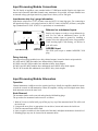
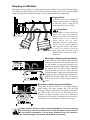
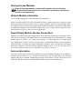
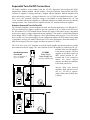
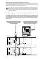
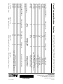
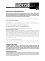
MODULE OWNERS MANUAL
Power
Processing
Modules
About Power Processing Modules
The rear panel of the CK family Power Processing amplifiers provides three bays (Input, Network
and Power/Output) configured to accept interchangeable plug-in modules. Your amplifier may have
been factory-configured with some of the optional modules. The back page of this manual contains
an overview chart of all currently available Power Processing modules.
“CC-” Modules fit into the Power/Output or Input module bays. These basic analog modules are
non-programmable and non-NexSys® compatible; only the Sequential Turn-On/Off (STO) function
can be controlled (through hardwiring).
“NC-” Modules can be controlled, programmed and/or monitored via the hand-held N-Coder, NCoder/PC software or over the NexSys network. Except for the STO feature, NC Modules are “tamper-proof” in that there are no user-accessible setup controls.
Programming NC Input Processing Modules
NC Input Processing modules can be programmed in OR out of the amplifier.
Programming with the N-Coder
Connected to an Input Processing module’s data port via the supplied RJ14-RJ14 cable, N-Coder
automatically identifies module type and displays only the parameters available for that module.
Users can then adjust parameters, audition the results, then store new settings in the module’s nonvolatile memory, or inside the N-Coder for later reference. Modules need not be powered, or even
installed in the amplifier for programming; N-Coder provides the necessary power. Parameters can
also be created ahead of time without any modules attached, stored in the N-Coder, then downloaded
into the module’s memory later. Except for DSP modules, all NC Input Processing modules can be
programmed from an N-Coder.
Programming with N-Coder/PC software
N-Coder/PC Software, a Windows®-based program that configures all Input Processor NC modules,
will run on any PC with Windows ‘95 or 3.1. The computer’s parallel (printer) port is used with a
DB25 to RJ-14 adapter and cable (both supplied) that connects to the Input Processor NC module.
Programming with Octopus
Crest Audio’s LCP-AC8 “Octopus” is a one rack space, Locally Controlled Processor that adds
‘Snapshot’ capability to the CK family of Power Processing amplifiers. Octopus is compatible with
all NC Input Processing modules, and can activate functions including sequential power control,
level attenuation, analog EQ, crossovers, and all DSP parameters. The Octopus may be integrated
with third-party RS-232C system controllers.
Programming with NexSys
Using the appropriate NC Network module, NC Input and Power/Output modules can be controlled,
programmed and/or monitored remotely through the use of NexSys. NexSys is Crest Audio’s hardware and software package that offers network connection of Crest Audio amplifiers and associated
devices, along with diagnostic facilities.
Input Processing Module Connections
The CK family of amplifiers come standard with a CC-IPB Input module. Barrier strip input connectors and removable individual channel rotary attenuators are provided. All Input modules have
an internal voltage gain/input sensitivity jumper that is factory-set for X40 gain.
Input barrier strip lug / gauge information
Input barrier strips have a 0.325" (8.3mm) center and 0.270" (6.9mm) lug space. For connecting to
the input barrier strips, a wire gauge between 14 AWG (2.5mm2) & 24 AWG (0.25mm2), and spade
lugs (Panduit Part No. PNF 18-6LF-C or equivalent) are recommended.
Balanced vs. unbalanced inputs
SEE INSTRUCTION MANUAL
Level
4 5 6
A
3
7
2
1
0
Input A
+
–
Input B
+
8
9
10
Level
4 5 6
B
3
7
2
1
–
0
8
9
10
Model
CC-IPB
Input Barrier Strip
Input Level
Attenuators
Barrier strip inputs are ready to accept balanced signals. For use with an unbalanced source, tie the
inverting (minus) input to ground by installing a
jumper across the appropriate barrier strip terminals.
If the inverting input is left floating, a 6 dB loss in
gain will result.
AES/EBU Input
This XLR jack accepts a standard AES/EBU XLR
plug.
Daisy chaining
Some Input Processing modules have daisy-chained outputs, located on barrier strip terminals.
NC-AES and NC-DSP-D modules have balanced daisy chain outputs.
NC-DSP-A and NC-SEQ modules have unbalanced daisy chain outputs.
NC-MCO and NC-MEQ modules have unbalanced mono HP/LP daisy chain outputs.
The NC-SCO module has unbalanced stereo HP/LP daisy chain outputs.
NC-IPE page input & enable connections
Get information from engineering
Input Processing Module Attenuators
Operation
Channel attenuators (A&B) are used to control signal level. Ideally, the amplifier should be operated with the controls at 0dB attenuation. When the amplifier is being used in bridged mono mode,
both attenuators must at the same level.
Knob Removal
The attenuator knobs can be removed and replaced with blanking plugs.
The procedure for attenuator knob removal is as follows:
1. With an X-Acto or similar knife, pop off the grey key cap of the attenuator knob. This will reveal
the inside nut.
2. Using needle nose pliers or appropriate size nut driver, loosen and remove the inside nut.
3. Slide the attenuator knob off the shaft.
4. Insert a regular screwdriver in the slotted end of the shaft, and adjust attenuation to desired level.
5. Blanking plugs may now be inserted in the attenuator holes.
Input Processing Modules - Internal Options
Input sensitivity/voltage gain jumper
Input modules have user-settable jumpers to configure Input Gain/Sensitivity. These internal
jumpers (two for CC-IPB, three for all input NC modules), labeled “W1 W2 W3”, are used to set
the overall gain of the amplifier.
The 3 positions (shown at left) allow
the amplifier to be set for constant gain
of X20 (26 dB), X40 (32 dB), OR constant sensitivity for full output (.775V)
+26dB
at 0 dBu input. The standard factory
0dBu
+26dB
+32dB setting is for X40 (32dB). All jumpers
0dBu
+32dB
must be set to the same position as
X40 (+32dB) Standard Factory Setting
shown.
Channel A Jumper
Channel B Jumper
NexSys Indicator Jumper (NC-IPN Only)
+26dB
0dBu
+26dB
+32dB
0dBu
+32dB
+26dB
0dBu
+32dB
.775V / 0 dBu (For Full Power)
+26dB
0dBu
+32dB
X20 (+26 dB)
+26dB
0dBu IN
+32dB
CREST AUDIO
26C2197-02
To change jumper settings, the Input
module must first be removed from the
amplifier.
W1
W2
A
B
Warning! Amplifier must
be removed from AC
mains supply before this
operation is undertaken!
The diagram at left shows the location
of these jumpers on the CC-IPB module. The diagram at the lower right
shows the location of the jumpers on
the NC-IPN module.
Input Gain/Sensitivity Jumpers
NexSys/N-Coder jumper
All NC Modules have internal jumpers used to set the module for operation with NexSys or NCoder. These jumpers are labeled “W4 W5” on the Input module circuit board.
Input Gain/Sensitivity Jumpers
N-Coder Setup
N-CODE
NC-NXS
NexSys Setup
CREST AUDIO
26C2797-02
N-CODE
NC-NXS
W2 W1 W3
+26dB
0dBu Sen
+32dB
N-CODE
NC-NXS
The “NC-NXS” jumper position
allows operation with NexSys,
Nexsys / N-Coder Jumpers
while the “NCODE” jumper position permits the Input module to be programmed through N-Coder or N-Coder/PC software when
the amplifier is off.
W4 W5
Note: Factory setting is the ‘NexSys’ position. If NexSys, N-Coder, or N-Coder/PC software is not
being used, jumper position will have no effect upon the operation of the amplifier.
Swapping out Modules
Only jumper setting changes or module upgrades require modules to be removed from the amplifier. Contact Crest Audio Customer Service for full details on module removal. The ‘General Module
Setup’ diagram indicates the general setup of the rear panel module/bay configuration.
Required Tools
A Phillips screw driver. Should the
module jumpers need to be changed
or removed, a pair of long nose or
needle nose pliers is also useful.
Precautions
If Load Monitoring is
employed, an additional ribbon
cable will be located here.
Network Module
Input Module
Designed & manufactured in the USA by:
Crest Audio Inc.
100 Eisenhower Dr.
Paramus, New Jersey 07652 USA
Model
Name
Output Power
@70.7V
Model
Name
Output Power
@8Ω/Ch.
CKV 100
CKV 200
CKV 400
CKV 800
CKV 1600
CKV 2400
50W
100W
200W
400W
800W
1200W
CKS 100
CKS 200
CKS 400
CKS 800
CKS 800-2
CKS 1200-2
CKS 1600-2
50W
100W
200W
400W
400W
600W
800W
Network
Address
Data
5 4 3 2
6
9 8 7
9 8 7
Hi
DCBA
6
Model
NC-NXS
1 0 F
DCBA
+ –
E
5 4 3 2
1 0 F
E
+ –
Lo
Ribbon Cable from
Network Module, if fitted
SEE INSTRUCTION MANUAL
Level
4 5 6
A 3
7
N-Coder
Data
Port
2
1
0
+
–
+
8
9
10
Level
4 5 6
B 3
7
Input B
Input A
2
1
–
0
Model
NC-IPN
8
9
10
Amplifier is shown with the top
cut away for clarity only. Dangerous
voltages exist inside, and only a Crest
Audio-certified service technician
should remove the top cover!
Removable modules contain staticsensitive devices; handle modules at
static-safe work stations! The amplifier MUST be switched off and the
mains plug removed from the supply
before module removal operation is
undertaken.
Removing or Replacing an Input Module.
Remove the four #8 3/8" Phillips pan head sheet
metal screws that secure the module to the chassis. The module is connected electrically to the
amplifier via multi-pin ribbon cables. Unplugging
the module from the ribbon cable connectors
frees the module for removal. To insert the same
or another module, simply reverse this procedure,
making sure that any ribbon cable connectors are
properly and securely seated. Note: The amplifier
must not be operated without an Input module in
place.
Removing or Replacing a Network Module.
This process is the same as that for removing/replacing an
Input module. Be aware, though, that if an NC-NXS
Network module is being removed or replaced, four multipin ribbon cables will need to be disconnected. Note:
Standard CK family amplifiers come with a blank panel
installed in the Network bay. The amplifier must not be operated without a Network module or blank panel in place.
SEE INSTR
CLASS 2 WIRING
MAY BE USED
Output
N-Coder
Data
Port
–
A
Error
+
PUSH
+
B
–
Signal
Ground
Lift
Jumper
Designed & manufactured in the USA by:
Crest Audio Inc.
100 Eisenhower Dr.
Paramus, New Jersey 07652 USA
Model
Name
Output Power
@70.7V
Model
Name
Output Power
@8Ω/Ch.
CKV 100
CKV 200
CKV 400
CKV 800
CKV 1600
CKV 2400
50W
100W
200W
400W
800W
1200W
CKS 100
CKS 200
CKS 400
CKS 800
CKS 800-2
CKS 1200-2
CKS 1600-2
50W
100W
200W
400W
400W
600W
800W
Network
Address
5 4 3 2
6
DCBA
6
Model
NC-NXS
1 0 F
DCBA
9 8 7
Hi
E
5 4 3 2
1 0 F
E
+ –
9 8 7
Data
+ –
AES/EBU
In
Lo
DO NOT attempt to replace or remove a Power/Output Module. This module can only
be serviced by a Crest Audio certified service technician. Please consult your dealer, Crest Audio representative, or Crest Audio Customer Service for assistance.
User-inflicted damage to this module will invalidate your warranty.
Storing Unused Modules
Power Processing modules contain static-sensitive devices; therefore
unused modules must be stored in a static-safe environment, preferably at
normal room temperature!
Network Module Information
The CC-BLK (blank panel) comes standard with all amplifiers.
When a Network module (NC-NXS) is installed in this bay, network connection is made via a pair
of three-pin Phoenix-type connectors. They are wired in parallel, and form a loop-through connection. (Mates for these connectors are shipped with the Network module.) Network bus addressing is
accomplished through use of the Hi and Lo Address dials. See the NexSys Software manual for more
information on NexSys bus connection and configuration.
Power/Output Module Speaker Connections
Speakers are connected using the Output Barrier Strip connectors. Spade lugs, ring tongues or bare
wire may be connected to the output barrier strip elements. Spade Lug measurements for Output
barrier strip are as follows: .44" (11mm) screw spacing, .32" (8mm) lug space. For output spade
lugs, Panduit Part No. PNF 14-8LF-C (or equivalent) is recommended. Make sure the amplifier is
turned off before you change any output connections or jumpers. Also ensure that the load impedance being connected is not less than the amplifier's ability to drive it. See the CK family Power
Processing Amplifier Manual for more information on speaker connection.
Service Information
For service, contact your nearest Crest Audio Service Center, Distributor, Dealer, or Crest Audio Inc.
Customer Service directly at: Tel. 201.909.8700 (USA) Fax. 201.909.8744 (USA). For technical
inquiries only, the Crest Audio Technical Services Dept. can be faxed at 201.587.0550 (USA). Crest
Audio may also be contacted on the World Wide Web at: http://www.crestaudio.com.
Sequential Turn-On/Off Connections
CK family amplifiers come standard with the CC-STL Sequential Turn-On/Turn-Off (STO)
Output/Power module installed. On this module, a four-pin Sequential Turn-On/Turn-Off (STO)
connector is supplied. A mating connector is shipped with the amplifier. With the amplifier front
power switch set to “remote”, a voltage of between +8 to +18 VDC can be applied across the “Com”
and “+8 to +18V” terminals. When the voltage is on/available, a closure between the “In” and
“Com” terminals will turn the amplifier on. Additional amplifiers are added to the turn-on chain by
looping from the “Out” terminal of one amplifier into the “In” terminal of the next amplifier.
Standard Sequential Turn-On/Turn-Off.
For CK family amplifier systems configured for basic non-NexSys applications, (CC-IPB with CCSTL) an external power supply is needed to provide a nominal +8 to +18 Volts to each STL module. The number of CC-STL modules that an external DC supply will be able to power is dependent
on the power supply’s voltage output and current capability. Crest Audio’s external Direct Plug-In
Power Supply Unit (CC-WW1) supplies 9 volts at 300 milliamps and can power 15 CC-STL modules. Use only a two-wire power supply! If your configuration requires the STO control of more than
15 amplifiers, contact Crest Audio Customer Service for more information. (Note that module CCSDC has an integral STO power supply, and does not require CC-WW1).
The “Com” and “+8 to+18V” terminals on each CK family amplifier are bussed together in parallel
and connected to the DC supply. The “Out” terminal of each CK amplifier is connected to the “In”
terminal of the next CK amplifier
in the turn-on sequence. The first
Standard Sequential
CC-WW1
amplifier in the chain requires an
Turn-On/Off
Direct Plug-In
SPST closure between it’s “In”
(max. # of amplifiers is
Power Supply Unit
terminal and “Com” terminal to
15 per CC-WW1)
+8 (min) to +18VDC (max)
initiate the power turn-on
sequence and keep the amplifiers
in the chain powered on.
+8 to 18VDC
20 mA
LISTED 8B42
COMMERCIAL
POWER
AMPLIFIER
In
120V~60 Hz 15A
Out
Com
NEC
CLASS 2 ONLY
+8 to 18VDC
20 mA
LISTED 8B42
COMMERCIAL
POWER
AMPLIFIER
In
120V~60 Hz 15A
Out
Com
NEC
CLASS 2 ONLY
Turn-on delay time between
amplifiers fitted with basic modules (i.e., CC-STL) is approximately 100ms, turn-off delay time
is 200ms.
Manual or NexSys-Compatible Sequential Turn-On/Turn-Off.
CK family amplifiers fitted with a NexSys-compatible NC Power/Output Module (NC-STI, NCSAC, NC-SLM) may be powered up via NexSys OR with a manual switch closure. If NexSys is
employed, the STO delay time is also software-controllable.
Note: when using NexSys control, hard-wiring for manual switch closure between amplifiers should be used cautiously. If the switch closure output is wired up, it WILL cause the
next amp to switch, regardless of which source (hardware switch or NexSys STO) has initiated the command.
The modules (and the non-NexSys compatible CC-SIO) feature a 6-pin connector providing a 3wire input from switch closures (or from a CK family amplifier) and an opto-isolated 3-wire output
to another CK amplifier. The 3-wire signals are: ON, OFF, and COM. To initiate either the ON or
OFF function manually, simply provide a closure from the proper signal line to COM; after a time
delay of approximately 200ms, the closure is echoed on the 3 isolated output signal pins to initiate
the turn-on function in ‘downstream’ amplifiers. The on/off closures can be either momentary or
constant contact.
Manually Initiated (hard-wired) Sequential
Turn-On/Off using NexSys-compatible
Power/Output Modules
NexSys-Initiated Sequential Turn-On/Off
using NexSys-compatible Power/ Output
Modules (unlimited # of amplifiers)
®
On
Off
PC
Output
NC-NXS
In
On
Com
Off
On
Com
Off
Out
Output
In
On
Com
Off
On
Com
Off
Out
NC-NXS
Daisy Chain Out
Programmable
Gain Control
Gain Control
Analog Input DSP
Digital Input DSP
Gain Control, Priority Page
Gain Control
Gain Control, 2-way Xover
Gain Control, Mono EQ/2-way Xover
Gain Control, Stereo Xover
Gain Control, Stereo EQ
Module Functions
Crest Audio reserves the right to make improvements in manufacturing or design which may affect specifications.
Crest Audio specification literature is available in downloadable PDF file format; visit our website at
http://www.crestaudio.com. NexSys is a registered trademark of Crest Audio Inc. ©1997 Crest Audio Inc.
Input Connection
N
Y
Y
Y
Y
Y
Y
Y
Y
Y
Computer Sequential
Turn-On/Off Control
N/A
BS
UBS
BS
N/A
N/A
MXO
MXO
SXO
UBS
Twisted Pair Data
Bus Connection
6P-Six Pin
SXO-Unbalanced Stereo Crossover
Voltage/Current Monitor
Volt./Curr. & Load Monitor, Audio Return
Advanced NexSys functions
NexSys
Control
Self-powered
Y
STO Connection
Y
NexSys-Compatible
N
Y
N
Y
Y
Y
4P-Four Pin
MXO=Unbalanced Mono Crossover
4P
6P
4P
6P
6P
6P
B-Barrier Strip
UBS=Unbalanced, Stereo
N
N
N
Y
Y
Y
Y
B
A
B
A
B
B
B
B
B
B
Power Processing Modules - Overview
Input Processing Modules
CC-IPB
NC-AES
NC-DSP-A
NC-DSP-D
NC-IPE
NC-IPN
NC-MCO
NC-MEQ
NC-SCO
NC-SEQ
Network Modules
NC-NXS
Power/Output Modules
CC-SDC
CC-SIO
CC-STL
NC-SAC
NC-SLM
NC-STI
A-AES/EBU
BS-Balanced, Stereo
Printed in USA
v. 1.1 11/6/97
A3300044
Crest Audio Inc.
100 Eisenhower Dr., Paramus NJ 07652 USA
TEL: 201.909.8700 FAX: 201.909.8744
http://www.crestaudio.com