1
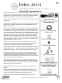
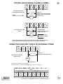
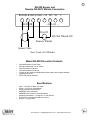
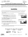
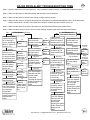
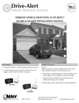
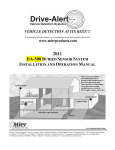
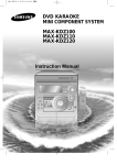
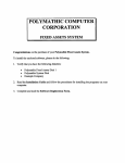
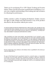
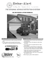
THE ORIGINAL VEHICLE DETECTION SYSTEM!
DA-500 INSTALLATION MANUAL
THE BASICS
MORE OPTIONS
1
3 Add a remote chime in the front room to alert those
on the first floor
A sensor(s) detect(s) a vehicle entering a monitored
area
2 A control panel receives a signal from the sensor
and triggers an alert-whistle inside the control panel
DA-500 Drive-Alert
4 Add another chime in the basement to alert those
downstairs
5 Add a third chime in an upstairs bedroom to alert
those upstairs
6 Add a wireless or hard-wired timer controlled light
kit to turn on outdoor lights, indoor overhead lights,
and/or lamps to warn strangers or welcome friends
7 Attach video surveillance to record activity and
display the driveway on a monitor inside
8 Add a portable chime to alert those in the backyard
pool, garden or deck
9 Activate signs, gates or other equipment
TABLE OF CONTENTS
Page
Content
Cover Page
1
Table of contents
2
Introduction to the DA-500 and Accessories
3-4
Installation Guide
5
Operation Instructions
6-7
Schematics for using the DA-500 to control other alarms and chimes
7
DA-500ContentsandSpecifications
8
DA-655 Installation
9
Technical Support and Warranty Information
10
Troubleshooting Guide
DA-500 Drive-Alert vehicle detection system
800-473-0213 | [email protected] | www.mierproducts.com
1
2
Model DA-500 General Information
Drive-Alerts are perfect for use in residential driveways, on farms, at drive-up
windows, in remote locations, and to protect valuable assets and equipment
such as tractors or constuction vehicles. The Drive-Alert will detect a vehicle
approaching, or whenever a vehicle or metal equipment is moved.
The Drive-Alert detects any metal which contains iron. It will not detect copper
or aluminum.
The Drive-Alert’s method of operation is to sense the change in the magnetic
field around it. This field is always present, and is disrupted when a metal
object moves through it.
The key element in the Drive-Alert installation is to locate the sensor/probe in
the area where you wish to detect this change. The usual installation is near
the entrance of a driveway, but located far enough away from roads or streets
so as not to detect traffic. Moving ferrous (iron) metal trips the sensor. Larger
metal objects are detected easier than smaller. Faster moving metal objects
are detected easier than slower. Metal moving nearer the probe is detected
easier than metal moving farther away. These are the three factors which
determine the system’s range of detection. Therefore, trucks traveling 65 mph
can be detected up to 50 feet; cars moving 4 mph up to 8 feet; and a walking
person with steel toe shoes up to 1 foot.
The Control Panel houses the electronics which allows the Drive-Alert to
function. It also contains an annunciator, and the terminal strip permits the
attachment of the probe as well as accessories or other devices.
The DA-500 includes a
Control Panel, Sensor, and 100 feet
of direct burial cable
DA-051-___ Probe with longer
lengths of cable
DA-655 Chime with Volume
DA-052V Remote Whistle
Longer lengths of cable are available. Simply order a DA-500CP (control panel only) and a DA-051-___ where you fill in the blanks for the amount of cable
needed in 50’ increments. Ex: DA-051-250 is a sensor with 250’ of cable.
A Hard-Wired DA-655 Chime with Volume is the most popular accessory for
the DA-500, and is HIGHLY recommended for all business, drive-up window, and high-traffic areas where a DA-500 is used. The chime is far more
pleasant than the standard whistle inside the DA-500 Control Panel, and the
volume control makes it far more versatile.
A DA-505 Hard-Wired Timer Control unit is available. It is housed in a separate box and is attached by wires to the terminal strip on the Master Control
Panel. This Timer Control turns on lights, usually outside lights, for an adjustable period when a vehicle is detected.
The Hard-Wired DA-052V allows you to add additional alert whistles to the
DA-500.
DA-505 Timer Control
DA-066 Wireless Transmitter for
wireless chimes pictured with a
Wireless DA-068 Chime and a
Wireless DA-070 Chime
Wireless chimes are available with the DA-066 Chime Transmitter. This
transmitter easily hooks up to the contacts on a DA-500 and triggers DA-068
Plug-in chimes and DA-070 Battery-powered Portable Chimes.
Wireless light control is available with the DA-606LK with timer control.
DA-606LK Wireless Light Kit
800-473-0213 | [email protected] | www.mierproducts.com
INSTALLATION page 1 of 2
3
The Control Panel is generally located in a closet, utility room, or garage. If the only noisemaker used (remotes are
available) is the one contained within the control panel, the panel must be located where users can easily hear the
“whistle.” The control panel is not suitable for outdoor installation. Also, 120 volt AC power must be available. The ease
of routing the three-wire cable from the sensing probe should be considered when deciding the location of the panel. The
control panel is usually attached to the wall with screws.
Improper installation is the No. 1 reason for system malfunction. Please use caution when installing the sensing probe to
assure a properly operating Drive-Alert.
The probe’s sensor is a coil of wire wrapped around an iron rod. Its resistance is 700-1100 ohms. The red and black wires
connect to the coil. It is encapsulated in epoxy to protect it from physical damage and moisture.
DO NOT CUT OR NICK THE CABLE JACKET!
If moisture enters, false alarms will be the result!
Mier HIGHLY recommends burying the cable within 1/2-inch PVC pipe for added protection to the cable.
The cable is made with an extra thick outer cover. There is a foil wrapper surrounding the red and black wires. There is
a silver (bare) wire in the foil. False alarms will occur if moisture gets into the foil wrapper. Nicks in the outer cover and
improper splices allow moisture to enter the cable. As moisture enters the cable, the resistance decreases. Resistance
between the red or black wire to the shield wire must be infinite. (Use meter with ability to read resistance above 20 million
megaohms).
The ideal installation is without any splices. The use of cable other than that which is designed for the Drive-Alert is
undesirable. Improper splices and unsuitable cable are major causes of false alarms. If splicing is unavoidable, splice the
cable using a 3M SLiC-TM SPLICE KIT, or equivalent. The splice kit is available from Mier Products.
The sensing probe does not know if it is in or out of the ground, but it must remain absolutely motionless. Most probes are
buried 6 inches deep and parallel to the driveway. Be sure to protect it from physical damage.
The cable is made for direct burial in the ground. Do whatever is necessary to protect it from physical damage to the outer
cover, such as using 1/2-inch PVC pipe.
The probe responds to changes in the magnetic field around it. The signal produced by the coil is a few micro volts for a
fraction of a second. The probe and cable must not be within 20 feet of electric wires because they have changing magnetic fields of their own. Never bury the sensor in the same trench with other electrical wires, including telephone wires
and wires for lights, bells, etc.
You may wish to place a sensing probe atop the ground in the general area of where you wish to bury it, and connect the
cable to the control panel. This will allow you to TEST the system in application BEFORE final installation. It would be
acceptable to leave the sensing probe and cable above the ground for a couple of days, but make certain it is not
damaged during this period. This method should not be used permanently. See OPERATIONS INSTRUCTIONS for
adjustments which may be necessary.
The burial of the probe is ideal in the center of the area being monitored, but often is not practical. If a new driveway is
being put in, the sensing probe could be buried a minimum of 12-24 inches deep. In case you wish to place the sensor in
the center of the drive, the cable and sensing probe could be placed in a 1 1/2 inch piece of PVC to provide protection.
The cable should also be protected whenever vehicles move over it.
The usual installation of the sensing probe is parallel to an already existing driveway. In this case, the probe can be buried
6 inches deep, and the cable simply placed below the grass line. However, if vehicles are going to travel directly over the
probe and cable, they should be buried deeper.
The sensing probe may be placed up to 5,000 feet from the Control Panel. Up to 4 sensing probes can be attached to one
panel, but each additional probe reduces every probe’s ability to detect. The Drive-Alert will not know which sensing probe
detects a vehicle.
800-473-0213 | [email protected] | www.mierproducts.com
4
INSTALLATION page 2 of 2
When more than 1 probe is used, connect the red and black wires in series. Connect
the silver wires in parallel. The red wire from one cable is soldered to a black wire from
another cable. The remaining red wire & black wire are attached to the Drive-Alert
terminals. All silver wires are attached to the Drive-Alert.
Keep the probe, cable, and control panel at least 8 feet away from heavy power lines,
power panels, motors, arcing or sparking machinery, and radio transmitters. In some
cases, moving the panel and/or cable a few feet can solve interference problems.
FIGURE 1 illustrates the contacts on the bottom of the DA-500 Control Panel, with the
sensor correctly attached.
The sensing probe is a 1” x 12”
cylinder containing a sealed
sensor. Be cautious when
handling the sensor and
particularly careful to not nick
the cable attached to it.
SHEILD WIRE
BLACK
12’
A typical installation is the probe
6 inches deep parallel to drive,
which will allow the probe to
“sense” 12’ across the driveway.
SENSOR
RED WIRE
Bury the probe at least 6” deep.
12’
FIGURE 1
12’
The ideal installation allows you
to extend your detection
range by installing the sensor
under the center of drive.
800-473-0213 | [email protected] | www.mierproducts.com
OPERATION INSTRUCTIONS
5
The Drive-Alert is adjusted at the factory for maximum sensitivity for the probe and minimum time for the whistle. To adjust
these, open the control panel and adjust the small pots according to the diagram on the inside cover (see FIGURE 2). The
whistle “timer adjust” is adjustable from 1-12 seconds and the LED 3 will light.
When first plugged in, the red blanker LED 2 will remain on for only 1 minute, and the Drive-Alert will be muted for
approximately 1 minute each time the electrical power is turned on. It provides time for the electronic circuits to initialize.
During normal operation, the noise blanker detects unwanted electrical interference and mutes the Drive-Alert for a few
seconds. It has been adjusted at the factory. The blanker light should be off during normal operation.
To test the Control Panel, it is possible to rub your finger simultaneously on the three terminals to which the sensing
probe is attached. This should cause the system to go into false alarm. This will occur with or without the sensing probe
attached. Be sure the terminal screws are tight while making the test. If the system responds to this test, in almost all
instances it indicates a properly functioning control panel.
If false alarms occur, remove the sensing probe wires fron the Drive-Alert terminals. Let the power remain turned on to the
control panel. If the false alarm stops, then the most likely cause of the problem is moisture in the sensing probe cable.
Radio transmitters, cell phones, cordless phones, and wireless modems within 10 feet of the control panel may cause
false alarms.
Additional devices can be attached to the Drive-Alert on its terminals at the bottom of the control panel. When the whistle
switch is turned off, the Drive-Alert terminals can switch customer provided electrical current up to 5 AMPS. Never attach
any device that puts more than 30 volts on the Drive-Alert terminals. When the whistle switch is turned on, the Drive-Alert
terminals have available 24 VDC at 100 MA. Refer to the diagrams in this manual for hookup instructions.
Mier Products has a hard-wired “timer control” accessory available. The DA-505 Timer Control attaches to the Drive-Alert
terminals. This Timer Control is adjustable from 45 seconds to 45 minutes. It switches up to one thousand watts of 115 volt
power for outside lights. Mier Products also has a hard-wired chime available. The DA-655 Chime with Volume Control
is the most popular accessory for the DA-500, and is highly recommended for drive-up window or business applications.
Mier also has a wireless “timer control” kit (DA-606LK) which adjusts from 45 seconds to 45 minutes and includes a DA071 Light Switch and DA-072 Lamp Module to control lights as an alert in addition to the audible alert. Furthermore, Mier
has a wireless chime transmitter (DA-066) which triggers wireless DA-068 Plug-in Chimes and DA-070 Battery-powered
portable chimes.
Along with Mier’s accessories, the DA-500 can also trigger your other devices such as surveillance, bells,
sirens, signs, gates, and much more!
DA-500 CONTROL PANEL ADJUSTMENTS
BLANKER ADJUST
BLANKER
LED 2
MAX
MIN
TIMER ADJUST
1 AMP FUSE
LED 3 ALARM
MIN
MAX
SENSITIVITY
MAXIMUM CONTACT CURRENT IS 100 MILLIAMP AT
24 V WHEN USING DRIVE-ALERT VOLTAGE SUPPLY
SENSOR
RELAY
DO NOT CONNECT TO 120V AC
RELAY
POWER
LED 1
FIGURE 2
800-473-0213 | [email protected] | www.mierproducts.com
CONTROLLING EXTERNAL ALARMS & CHIMES
NEG
4
+24V
5
NO
6
External 24VDC Bell
DA-500 Whistle Switch ON
NOTE:
Limit of two external bells
C
8
Capacitor
0.1 Microfarads 100 Volt (min)
Adding a capacitor extends the
life of the relay.
BELL
NEG
4
NC
7
+24V
NO
NC
C
5
6
7
8
1N4004 DIODE
Adding the diode extends
the life of the relay.
External Relay Hookup
24VDC
To AC operated
CHIMES/ALARMS
RELAY
NOTE: If internal piezo whistle is not wanted, move the DA-500 Whistle Switch to
the OFF position and connect the jumper between +24 and the C Terminal
CONNECTION USING DRY CONTACTS & EXTERNAL POWER
NEG
4
+24V
5
NO
6
NC
7
C
8
Capacitor
0.1 Microfarads 100 Volt (min)
DA-500 Whistle Switch
MUST be OFF
BELL
External Power
Maximum current linited to 1 AMPERE
Maximum Voltage - 24 VOLTS (DO NOT apply 120VAC to terminals)
RED BLK SHLD NEG +24V
--- SENSOR --1
2
3
UNREG
4
NO
NC
C
7
8
--- RELAY --5
6
DO NOT CONNECT TO 120V AC
800-473-0213 | [email protected] | www.mierproducts.com
6
7
DA-500 Sensor and
Remote DA-052V Whistle Connection
RED BLK SHLD NEG +24 NO NC C
1
2
3
- SENSOR -
4
5
6
7
8
-- RELAY -DA-052
DA-500 Whistle ON
Remote Whistle
Sensor Cable
Note: Limit of 10 Whistles
Model DA-500 Drive-Alert Contents
•
•
•
•
•
•
•
Solid-state Master Control Panel
Electronic whistle with “on-off” switch
Red LED power-on indicator
UL listed transformer and cord
100 feet of two-conductor shielded direct burial cable; other lengths available
Weatherproof sensor
SPDT relay output available
Specifications
•
•
•
•
•
•
•
•
Input -- 120 VAC, 50-60Hz, 3.6 Watts
Output -- 24 VDC at 100 Milliamps
Surge protected from transients
Adjustable sensor sensitivity
Adjustable time control for electronic whistle
Operating temperature -- 20 degree F to 160 degree F
Provisions for activating optional timer control
Weight -- six (6) pounds
800-473-0213 | [email protected] | www.mierproducts.com
8
DA-655 Chime Installation Instructions
The DA-655 CHIME WITH VOLUME CONTROL is an optional feature for the Mier Products DA-500 and DA-600 Drive-Alert
vehicle detection systems. When wired to the Drive-Alert master control panel, it will sound a chime note each time the
DA-500 or DA-600 detects a vehicle. The DA-500 and DA-600 time adjustment can be changed to allow for a longer period of
time between chime sounds with repeating vehicle detection. The CHIME WITH VOLUME includes an on-off switch and volume
control.
Easy Installation
1. Remove the two #6 sheet metal screws from the side of the chime chassis and pull the base off the speaker enclosure.
2. Mount the chime chassis base within 10 feet of the DA-500 or DA-600 master control panel. The chassis base has
holes for a standard wall outlet box. The Chime is supplied with 10 feet of 4 conductor wire that connects to the
master control panel.
3. Assemble the chime speaker enclosure to the chassis base.
DA-500 with whistle OFF
RED
BLACK SHLD
NEG
+24DC
NO
NC
C
UN REG
4. Connect the 4 conductor wire to the master control panel as follows:
1) RED to +24 V terminal
2) BLACK to NEG terminal (DA-500), or GND terminal (DA-600)
3) Leave the GREEN AND WHITE wires disconnected for now
Black
Red
White
DA-655
Green
Red
Black
5. Turn the WHISTLE SWITCH on the DA-500 or DA-600 master control
panel to the OFF position. IMPORTANT: This whistle switch must be
turned off to use the DA-655 chime.
DA-600 with whistle OFF
6. Plug the master control panel into a 115 VAC outlet.
SIG ALA +5VDC GND +24DC
NO
NC
C
NO
C
UN REG
7. The chime should be turned on and adjusted for about 75% volume.
Momentarily touch the GREEN and WHITE wires together to trigger
the chime. Repeat as needed to set the chime volume for the desired level.
Black
Red
White
DA-655
Green
Red
Black
8. After the volume is set, connect the GREEN and WHITE wires as follows:
1) GREEN to NO, terminal #6
2) WHITE to C, terminal #8
9. Test the system by tripping the master control panel either with a vehicle test or using a manual technique described in
the master control panel documentation (DA-500 or DA-600).
The DA-655 works with any Drive-Alert Model
DA-500
DA-600
DA-605P
800-473-0213 | [email protected] | www.mierproducts.com
9
Mier Products’ Drive-Alert Technical Support
Mier Products, Inc. provides free telephone and email technical support for all of our Drive-Alert vehicle detection
systems. Call us at 800-473-0213 between the hours of 8:00 am and 5:00 pm EST, send an email to
[email protected], or download our Cut-Sheets, Instruction Manuals, or FAQs from our website:
www.mierproducts.com
Mier Products’ Drive-Alert Warranty
Limited Warranty for Drive-Alert Models and Accessories
Manufactured by Mier Products, Inc.
Mier Products, Inc.’s Limited Warranty Program for Drive-Alert models and accessories protects the original owner
for one year from the date of purchase against defects in original parts or workmanship. Mier Products, Inc. agrees
to repair or replace parts (Mier’s option) that are deemed defective by our Quality Control Team, without charge for
parts or labor, if the defective unit is returned prepaid to Mier Products, Inc., Kokomo, IN, 46901, within the oneyear period. Close inspection at the time of receipt by the customer will quickly determine product quality. Thus,
Mier Products, Inc. recommends inspection of Drive-Alert models and accessories immediately upon receipt, before
installation or driving to an installation site, and contacting Mier Products, Inc. if quality issues arise.
NOTE: Sensors and cables that have been buried are no longer covered. Wireless sensors that have been sitting in
Flooded areas or standing water are not covered.
Mier Products, Inc. does not assume responsibility for claims or damages caused by improper installation or use of
these products, accessories, and/or products connected to them. Mier Products, Inc. does not assume responsibility
for damages to these products or their accessories due to shipping damage or damage occurring while in a
customer’s warehouse and/or possession. Mier Products, Inc. does not assume responsibility for damage due to
accident, faulty wiring, overload of Drive-Alert or Drive-Alert accessory output, or components attached to the
Drive-Alert parts. Drive-Alert accessories and parts built by other OEMs (including but not limited to chimes, lamp
modules, light switches, bells, splice kits) are covered under their respective OEM warranties. Drive-Alert models
and accessories must be shipped, handled, stored, and installed with strict adherence to OEM installation
instructions.
This warranty constitutes the entire warranty with respect to Mier’s Drive-Alert Models and Accessories and IS IN
LIEU OF ALL OTHERS, EXPRESSED OR IMPLIED, INCLUDING ANY WARRANTY OR MERCHANTABILITY AND
WARRANTY OF FITNESS FOR A PARTICULAR PURPOSE AND IN NO EVENT IS MIER PRODUCTS, INC., OR
IT’S OEM PARTNERS, RESPONSIBLE FOR ANY CONSEQUENTIAL DAMAGES OF ANY NATURE
WHATSOEVER.
Any warranty OR sales questions should be directed to Mier Products at 800-473-0213, or via e-mail to
[email protected]
Repair work not covered by this Warranty is available for a nominal charge.
800-473-0213 | [email protected] | www.mierproducts.com
Wireless Vehicle Detection | Buried Sensor Systems | Driveway Alarms | Drive-Up Window Detection | Instrument Boxes | DVR & CPU Lockboxes
Flush-Mount Cabinets | NEMA Outdoor Enclosures | NEMA Temperature Controlled Enclosures | NEMA Rack Enclosures | Rack Shelves and
Drawers | NEMA/UL Non-Metallic Enclosures | Power Supply Boxes | Siren/Speaker Cabinets | Bell Boxes | Battery Cabinets | Transformer
Enclosures | Custom Enclosures and Fabrication | Custom Graphic Screening and Colors
DA-500 DRIVE-ALERT TROUBLESHOOTING TREE
10
Step 1 - Check to make sure the Power Light is on. If not, replace the internal 1A fuse, or send to Mier Products for repair.
Step 2 - Make sure the sensor is attached correctly and securely to the control panel.
Step 3 - Make sure the sensor is located close enough to detect moving vehicles.
Step 4 - Make sure the sensor is at least 20 feet away from underground or overhead power/phone lines or an invisible fence,
and the control panel is at least 15 feet away from cellular or cordless phones, wireless routers, etc.
Step 5 - Make sure the sensor is at least 50 feet away from the street/road traffic to prevent false alarms.
Step 6 - Make sure there are no nicks or cuts in the cable allowing moisture to get inside and cause false alarms.
New
False Alarms
Existing
Check sensor wire
connections at panel
Fix
for no shorting &
Correct
as
correct attachment
neded
(Red=T1, Black=T2,
Ground = T3)
Not fixed
Check sensor to
make sure it’s
secure and placed
20’ away from Main
Power/phone lines
Not fixed
Check panel is 15’
from cell phones,
cordless phones,
routers, etc.
Not fixed
Check sensor is 50’
away from street
Not fixed
Check for two-way
radio interaction
Still not fixed
Call Mier Products’
Free Tech Support.
They will work with
you and might
recommend
returning the system
to Mier Products for
diagnosis and
repair.
Fix
Secure,
increase
distance, or
cross lines at
right angles
Fix
Increase
distances
Fix
Increase
distance or
reduce
sensitivity
Fix
Install on
cable RF
Cable Clamp
(Radio Shack
#273-105 or
eq.)
New
Remove Shield
Fix
(bare) wire from
Replace
terminal 3 of terminal Sensor &
block and retry
Cable
Not fixed
Remove all sensor
wires from terminal
block and see if
panel is “quiet.”
Not fixed
Remove all
accessory wires
from terminal block
and see if panel is
“quiet”
Not fixed
Call Mier Products’
Free Tech Support.
They will work with
you and might
recommend
returning the system
to Mier Products for
diagnosis and
repair.
Fix
Replace
Sensor &
Cable
Fix
Replace
Accessories
No Detection or
Existing
Intermittent Detection
Check sensor
placment 1 foot max
away from edge of
driveway and 1 foot
max deep in ground.
Not fixed
Check sensor
resistance at 7001200 OHMS Red to
Black
Not fixed
Check sensor wire
connections at panel
for no shorting &
correct attachment
(Red=T1, Black=T2,
Ground = T3)
Not fixed
Check Blanker LED
located on circuit
board is OFF, and if
not turn fully
counter-clockwise
Not fixed
Check panel
sensitivity at MAX
and do finger test
across BK and S
terminals
Still not fixed
Check Blanker LED
is OFF and if not
turn fully counterclockwise
Not fixed
Place two fingers
across BK and S
terminals
Relay Clicked but there
was no Whistle
Flip Whistle-Switch
25 times and try
again.
No Relay
Click or
Whistle
Call Mier
Tech
Support
Relay
Clicks but
no Whistle
Call Mier
Tech
Support
Not fixed
Check sensor
resistance at 7001100 OHMS Red to
Black
Still not fixed
Call Mier Products’
Free Tech Support.
They will work with
you and might
recommend
returning the system
to Mier Products for
diagnosis and
repair.
Call Mier Products’
Free Tech Support.
They will work with
you and might
recommend
returning the system
to Mier Products for
diagnosis and
repair.
800-473-0213 | [email protected] | www.mierproducts.com
Fix
Replace
Sensor
and cable