1
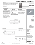
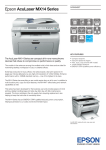
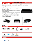
AA100
Access Air 100
Air Curtain System
TABLE OF CONTENT
Topic
Page
Disclaimer
Serial Number Identification
Introduction
Product Information
Specifications
Dimensions
Safety Information
Installation Procedures
Physical Installation
Electrical Installation
Operations
Modes of Operation
Maintenance
Maintenance Schedule
Daily
Monthly
Yearly
Service
Troubleshooting Guide (Cause and Effect)
Parts Lists
Parts List (Description/Part Number)
Schematics
Electrical Wiring Diagram / Warranty
3
3
3
2
4
4
4
5
7
8
8
8
8
9
9
9 / 11
DISCLAIMER
Ready Access Disclaims any Liability for any damage or harm caused to the AA100 Air Curtain, it’s
operator or any other equipment however caused if the AA100 Air Curtain is repaired or serviced by
anyone other than an authorized service engineer or Contrary to the manufacturers written
instruction contained herein.
This manual is intended for use by the in-house or authorized field service engineers and sales
representatives
The manufacturer maintains the right to update, add or issue a new service manual at any time
without notice, thereby rendering all previous issues obsolete.
Please write the Serial Number and Installation Date for your drive-thru window in the spaces
provided.
SERIAL NUMBER
Date of Installation
.
The Serial Number
Nameplate Is Located
on the Face Panel.
INTRODUCTION
The Ready Access AA100 Pass-Thru Air Curtain System is designed to be an integral part of your
drive-thru operation by protecting your workplace against the entry of insects and exhaust fumes,
while increasing energy efficiency by reducing air conditioning losses. Also satisfies health
department codes for fly fan applications.
3
Product Information
SPECIFICATIONS AND PERFORMANCE
Model
Number
Unit Voltage
USA
Actual
Unit
Amps
AA100
110/120 VAC
60Hz
Single Phase
5A
Air
Velocity
High / Low
2000/1800
FPM at Nozzle
Dimensions
In Inches
WxHxD
Weight
In Shipping
Carton
See Below
29 lbs
Dimensions
12" (305mm)
22" (559mm)
11 - 3/4" (299mm)
Figure 1
SAFETY INFORMATION
WARNING: To avoid the risk of Fire, Electric Shock or Injury to persons, observe the following:
Use this unit only in a manner intended by the manufacturer. If you have any questions, contact the
manufacturer.
Before servicing or cleaning the unit, switch the power off at the mechanical switch near the unit (Installed by
an Electrician) or the electrical entry service panel/circuit breaker. (Load Center)
OSHA LOCK OUT – TAG OUT procedures are to be observed to prevent power from being switched on
accidentally.
Any Installation and / or Electrical work must be done by QUALIFIED persons in accordance with all
applicable codes / standards and manufacturers recommendations and specifications.
When cutting into the wall or ceiling, DO NOT damage electrical wiring and/or other hidden utilities.
DO NOT use this fan with any solid-state speed control device.
DO NOT insert fingers and / or foreign objects into the Air Curtain.
DO NOT block or tamper with the unit in any manner while it is in operation.
DO NOT attach ductwork to this product or attempt to use it as a make-up air heater.
Such use voids the warranty and may create unsafe conditions.
This product must not be used in Potentially Dangerous locations such as Flammable, Explosive Chemical –
laden environment.
4
Installation Procedures
PHYSICAL INSTALLATION
Before you begin installing your Ready Access Air Curtain, you must determine what type of
installation will be required. Wood Frame, Masonry Framing, etc. See the illustration below to
determine your rough opening size and mounting.
Warning: Two people are required for the lifting and installation of the window.
ROUGH OPENING
43-3/4"
(1111 mm)
11-3/4" (299 mm)
2" (51 mm)
8-1/2"
(216 mm)
77-3/4" (1975 mm)
12"(305 mm)
ROUGH OPENING
36"(915 mm)
KNOCK-OUT FOR
ELECTRICAL ENTRY
13"
(330mm)
22"
(559 mm)
11-3/4" (299mm)
Nominal
60"
(1524 mm)
INSIDE VIEW
OUTSIDE VIEW
Figure 2
5
CONFIRM THAT THE CUSTOMER-SUPPLIED FRAME IS MADE TO ACCOMMODATE THE
DIMENSIONS AS ILLUSTRATED ABOVE.
1. Unpack AA100 unit from carton and inspect for shipping damage. Contact Ready Access as soon as possible if
damage has occurred. (800) 621-5045
2. A rough opening of 22-1/4" (565 mm) W x 12" (305 mm) H must be constructed before installation of AA100 unit.
3. Remove the (4) #2 phillips drive screws from the AA100 unit inside cover. This will allow access into unit once in
position of rough opening.
4. Position AA100 unit into rough opening, flush with inside of window unit. (Approx. 5" max. in from the outside of
window unit.)
5. Secure into position using the (4) 5/16" self-tapping screws provided through the mounting holes in the side panels of
unit. If mounting into masonry, use 1/4" (6 mm) masonry anchors (Not Provided).
6. Flash and seal unit on the outside to prevent water leaks and trim inside for cosmetics.
7. Close unit when completing installation using the (4) #2 phillips drive screws.
PLEASE COMMUNICATE WITH ELECTRICIAN ON UNIT AND INSTALLATION INSTRUCTIONS.
REINSTALLED SMALLER
TRANSOM GLASS
Tools Needed for Installation
¼” Nut Driver
⅜” Drill
5/16” Socket Adaptor to Drill
Caulk and Caulk Gun
4 5/16 “ x1” Self Tapping Screws
6
Electrical Installation
All power must be connected and wired by a qualified electrician and be in compliance with all state and local building
codes.
1.
Remove the (4) #2 phillips drive screws from the inside cover.
2.
Located in the upper right hand of AA100 unit, will be an electrical entry junction box.
Remove cover and expose (1) black wire (HOT), (1) white wire (COMMON) and (1) green wire (GRD).
WARNING - Disconnect power at service panel / circuit breaker before installation to AA100 unit.
OSHA Lock Out-Tag Out procedures are to be observed to prevent power from being switched accidentally.
3.
Route incoming 115VAC from ceiling (or where dictated from customer) in Solid, Flexible conduit or Commercial
Power Track for Cosmetics (MUST MEET STATE AND LOCAL CODES) into knockout provided on the face
panel of AA100 unit that leads into Electrical entry junction box.
4.
Connect wires together and insulate ends with wire nuts or crimp caps inside junction box.
Reinstall Electrical entry junction box cover.
5.
Press Push Button switch to test unit for operation.
6.
Close inside cover and install the (4) screws.
Electrical Entry
to Junction Box
7
Initial Window Operation
Modes of Operation
The AA100 has two modes of operation. Run and Shutdown.
Shut Down:
The main switch is in the “OFF” position.
The unit has no operations.
Run
The Main switch is in the “ON” position.
The unit functions as a “Fly Fan”.
If the AA100 does not operate correctly, go to the troubleshooting guide in this manual.
If the AA100 still do not operate properly, then call Ready Access at
1-800-621-5045
Each operator must read the operations manual before operating the unit.
Maintenance
Maintenance Schedule
Scheduled maintenance should be performed on a regular basis. This is to assure proper operation
and performance of the AA100 Air Curtain.
DAILY
Check the air vents and ducts for foreign materials.
(Anything that might cause restricted air flow or damage to the air curtain.)
The vents can be vacuumed or wiped down to remove any foreign material.
MONTHLY
Follow safety procedures before opening the unit.
Check the interior of the unit for any build up of any foreign materials using a dry cloth.
NOTE: KEEP ANY LIQUIDS OFF THE INTERIOR COMPONENTS.
Clean moving parts and lubricate with silicone or Teflon spray.
NOTE: Do NOT use Grease or Oils.
Semi Annual (6 Months)
Check all electrical and mechanical parts for proper operations
YEARLY
Have a service technician come in and perform a maintenance check on the unit.
IF NEEDED, CONTACT YOUR READY ACCESS SERVICE AGENT FOR SERVICE.
8
SERVICE
Issue
Probable Cause
Resolution
No Fan Operation.
No power to the unit.
Switch does not
Illuminate
Check / Reset the main circuit
breaker or switch.
Defective Main Switch.
Replace the switch.
Switch Option is not operating.
Find and correct problem.
Defective Blower.
Replace the blower.
Switch Option is not operating.
Find and correct problem.
No Fan Operation.
Switch Illuminates
Normally.
PARTS LIST
2
1
ID Number
Part Number
1
85001000
2
20010004
Description
Blower Assembly ( Dual Chamber) - AA100
Switch - AA100 on/off Push Button
9
10
WARRANTY:
Ready Access will only accept responsibility for manufacturing defects in the
product’s construction and/or materials.
Adjustments required during installation are the responsibility of the installer or
contractor and will not be covered under warranty.
Problems caused by improper installation are the responsibility of the installer or
contractor and will not be covered under warranty.
Ready Access, 1815 Arthur Drive, West Chicago, Illinois 60185, Tel: 630-876-7766, Tel: 800-621-5045
Fax: 630-876-7767, Email: [email protected], Website: www.ready-access.com
11
AA100 INSTALLATION SERVICE OPERATIONS MANUAL 11_19_08
Ready Access, 1815 Arthur Drive, West Chicago, Illinois 60185, Tel: 630-876-7766, Tel: 800-621-5045
Fax: 630-876-7767, Email: [email protected], Website: www.ready-access.com
12
AA100 INSTALLATION SERVICE OPERATIONS MANUAL 11_19_08