1
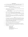
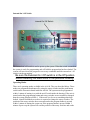
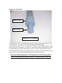
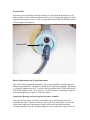
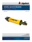
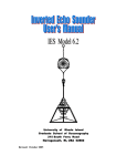
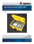
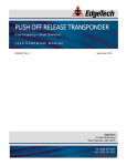
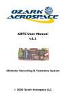
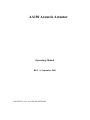
AA100 Acoustic Actuator
Operating Manual
REV. A, September 2001
COPYRIGHT © 2001. ALL RIGHTS RESERVED
Return Procedure
It is necessary to obtain from ORE Offshore a Returned Material Evaluation (RMA)
number prior to returning equipment. This is to assist tracking and arrival recognition.
Follow the procedure listed below when returning U.S. origin goods to prevent delays
and additional costs on Returned American Goods.
New Import Procedure/Returned American Goods
1.
All shipments must be accompanied by two copies of your commercial invoice showing
value of material and any reason for return.
*
2.
Whenever possible, please send copies of original export shipping documents
with the consignment.
If the value is over $1,000.00, the following shipper’s oath must be sent with the
invoices. (This can be typed on the invoice or on a separate letterhead.)
“I, ________________, declare that the articles herein specified are, the growth,
produce, or manufacture of the United States; that they were exported from the United
States; From the Port of ______________, on or about ___________; that they are
returned without having been advanced in value or improved in condition by any process
of manufacture or any other means, that no drawback, bounty, or allowance has been
paid or admitted thereof.
Signed _____________________”
3.
If more than one part per consignment, a packing list must also accompany the shipment.
It is acceptable to combine the commercial invoice and packing list as long as the
contents of each carton are clearly numbered and identified on the commercial invoice.
4.
Consign all air freight shipments to ORE Offshore in care of Intercontinental Air Frt.,
Inc., Logan Int’l Airport, East Boston, Mass. 02128.
5.
If the equipment is property of ORE Offshore please insure for full value.
6.
Route via Logan International Airport only as the final destination.
7.
Mail one invoice, packing list and copy of airway bill to ORE Offshore upon shipment.
8.
Please refer to issued Returned Material Evaluation number on all documents and
correspondence.
9.
Air freight must be prepaid on all returns.
ORE Offshore
4 Little Brook Road
West Wareham, MA 02576
Tel: (508) 291-0960 Fax: (508) 291-0975
Email: [email protected]
Standard Commercial Warranty
All equipment manufactured by ORE Offshore is warranted against defective
components and workmanship for repair at the plant in West Wareham, Massachusetts,
free of charge for a period of one year after shipment. Shipping costs are to be borne by
the customer. Malfunction due to improper use is not covered in this warranty and ORE
Offshore disclaims any liability for consequential damage resulting from defects in the
performance of the equipment. No product is warranted as being fit for a particular
purpose and there is no warranty of merchantability. This warranty applies only if: (i)
the items are used solely under the operating conditions and in the manner recommended
in Seller’s instruction manual, specifications, or other literature; (ii) the items have not
been misused or abused in any manner or repairs attempted thereon; (iii) written notice of
the failure within the warranty period is forwarded to Seller and the directions received
for properly identifying items returned under warranty are followed; and (iv) the return
notice authorizes Seller to examine and disassemble returned products to the extent Seller
deems necessary to ascertain the cause for failure. The warranties expressed herein are
exclusive. There are no other warranties, either express or implied, beyond those set
forth herein, and Seller does not assume any other obligation or liability in connection
with the sale or use of said products. Any product or service repaired under this warranty
shall be warranted for the unexpired portion of the original warranty period only.
Equipment not manufactured by ORE Offshore is supported only to the extent of
the original manufacturer’s warranty.
Acoustic Actuator
Functional description
The ORE Offshore model AA100 acoustic Actuator has been designed to provide
a reliable and cost effective means of remotely actuating a submerged device (relay,
solenoid, blasting cap, squib etc.). This product excels in the role of straightforward
acoustic solutions in the short duration, shallow water market. Under favorable
conditions, these devices provide the user with means of acoustic activating devices at
slant ranges in excess of 5 kilometers.
The model AA100 acoustic actuator is small, lightweight and has been designed
to present a minimal magnetic signature. This product is simple to use and no tools are
required to arm and operate the system. Operation of the model AA100 requires only
that it be switched on, connected to the device to be actuated and then sent its unique
command code from an ORE Offshore deck unit. The AA100 is compatible with ORE
Offshore and EdgeTech deck units: 8011, 8011A, 8011B, 8011XS and AMD200. The
acoustic command code structure employed in these devices is ORE Offshore’s field
proven BACS (binary acoustic command) command format. BACS commands are 16
bit, FSK encoded tone bursts, there are minimum transition requirements and no
command is re-issued. This command structure has been shown to be both secure and
reliable it has been widely accepted by the oceanographic community.
Command descriptions
• ARM: After receiving the ARM command the unit will charge up the firing
capacitors this takes 30 seconds after which the fire circuit will be enabled. When the
AA100 is charging the output stage, it will not act on any commands the receiver is
locked out for the entire 30-second charge period. The system will remain armed for
5 minutes, during this time the fire circuit remains charged and will fire if the fire
command is received. After the 5 minute armed period, the system discharges the
capacitors and must be re-armed before firing.
• FIRE: The AA100 unit will not act on a FIRE command unless the system has been
armed and the 5-minute timeout has not elapsed. If the fire circuit is charged the
system will fire immediately upon receiving a FIRE command.
Internal On / Off Switch
Internal On /Off Switch
The internal on / off switch is used to power up the system. When the switch is turned on
the system is ready for programming and will hold the program that has been loaded. The
system will not execute the program or act on any commands until the external on / off
switch is in the on position.
Be sure the External On / Off switch is in the Off position
before installing the electronics in the pressure housing.
Operating Modes
There are 4 operating modes available in the AA100. They are described below. These
modes are programmed and entered by using the rotary switches and the push button
switch on the electronics board inside the AA100. The system must be programmed
within 1 minute of turning it on with the on/off switch inside the housing. If the unit is
turned on but the programming button and rotary switches are not touched or changed
then the system defaults to Mode 1. If the mode is to be set to something other than
default, a small flat bladed screwdriver is required to change the rotary switches. The
position of the rotary switches does not matter unless the program button is pressed
within 1 minute of turning the system on. If the program button is pressed within 1
minute of power up the system will read the position of the rotary switches and set the
mode and timer accordingly. On power up (Switching the internal On / Off switch to the
on position) the internal on board LED will flash once, if the Program Button is pressed
within 1 minute after this flash the LED will flash once more indicating that and mode
and timer switch settings are being loaded. After the mode is set the internal LED will
flash the number of times to indicate the mode that was set. 1 flash equal’s mode 1, 2
flashes equals mode 2, 4 flashes equals mode 4, and 8 flashes equals mode 8. It is best to
set the rotary switches before turning the system on, this is simply to make it easier to
program the unit within the 1-minute timeout. Remember the position of the switches
doesn’t matter unless the program button is pressed. In the event of an improper mode
setting (an unsupported or unimplemented switch position) the led will flash 10 times
quickly and return to the default Mode 1. Please read the mode descriptions below
carefully.
Mode Switch
LSD Timer Switch
MSD Timer Switch
Program Button
Internal LED Indicator
Mode 1
This is the default mode the system will power up in this mode unless the programming
button is pressed. The system will enter this mode if the mode rotary switch is in the 1
position when the program button is pressed. The MSD and LSD timer rotary switches
have no effect in Mode 1. In mode 1 when the external on / off switch is turned to the on
position the unit will not respond to any commands for 10 minutes. After 10 minutes the
system will be ready and able to receive an arm command and then a fire command. If
the external on / off switch is turned off the system can be turned on again however the
10 minute time out will start again. This time out is intended to allow users to evacuate
the area before any arming and or firing can take place.
Mode 2
This mode is similar to Mode 1. The system will enter this mode if the mode rotary
switch is in the 2 position when the programming button is pressed. The timer rotary
switches are used to set the delay time before the system is capable of being used. In
mode 2 when the external on / off switch is turned to the on position the actuator will act
on commands received only after the time set on the MSD and LSD timer switches has
elapsed. The delay can be set from 0 to 99 minutes. The MSD switch indicates 10-minute
intervals and the LSD indicates 1-minute intervals. The unit will not respond to any
commands for number of minutes set on the timer switches. After the timeout the system
will be ready and able to receive an arm command and then a fire command. If the
external on / off switch is turned off, the system can be turned on again however the time
out will start again. This time out is intended to allow users to evacuate the area before
any arming and or firing can take place.
Mode 4
This mode is similar to Mode 1 and 2. The system will enter this mode if the mode rotary
switch is in the 4 position when the program button is pressed. The MSD and LSD timer
rotary switches are used to set the delay time before the system is capable of being used.
In mode 4 when the external on / off switch is turned to the on position the actuator will
act on commands received only after the time set on the timer switches has elapsed. The
delay can be set from 0 to 99 days. The MSD switch indicates 10-Day intervals and the
LSD indicates 1-Day intervals. The unit will not respond to any commands for number of
days set on the timer switches. After the timeout the system will be ready and able to
receive an arm command and then a fire command. If the external on / off switch is
turned off the system can be turned on again however the time out will start again. This
time out is intended to allow users to deploy systems for longer periods of time. It will
normally be used in study type mooring deployments. It is intended for recovery of
deployed instruments.
Mode 8
This mode is the timed fire mode. It intended for use when a deck unit is not available or
the acoustics in the area are bad. In the mode the system will fire immediately after the
timer has elapsed. There is no command required. The system will enter this mode if the
mode rotary switch is in the 8 position when the programming button is pressed. The
timer rotary switches are used to set the delay time before the system charges and then
fires. 30 seconds before the time is elapsed the fire circuit will start charging and then the
circuit will fire. The delay can not be set to 0 minutes. If the delay is set to 0 minutes the
system will report a mode error (10 quick flashes on the Internal LED) and go to the
default mode. The delay can be set from 1 to 99 minutes. The MSD switch indicates 10minute intervals and the LSD indicates 1-minute intervals. In mode 8 when the external
on / off switch is turned to the on position the actuator will start timing and fire
accordingly. Turning the external on / off switch to the off position will disable the
system.
External On / Off Switch
Switch Collar
Switch Shaft
External On / Off Switch
The external on / off is a watertight rotary switch. It can be operated underwater as well
as on the surface. The system is off when the switch shaft is turned fully
counterclockwise. The system is on when the switch shaft is turned fully clockwise. Total
travel of the shaft is 90 degrees. The surface of the collar and the switch shaft are knurled
for maintaining an easy grip while using the switch. To use the switch, hold the collar
with one hand and rotate the switch shaft with your other hand. The switch shaft will stop
at either the on or the off position depending on the direction of rotation.
Be sure the External On / Off switch is in the Off position
before installing the electronics in the pressure housing.
External LED
When the system is turned on using the External on / off switch the External Led will
flash a number of times indicating which mode is set. It will also begin timing if a mode,
which includes timing, is active. After 2 seconds the External LED will flash the number
of times equal to the mode set.
External LED
Battery Replacement and O-ring Maintenance
The AA100 requires minimal maintenance. The O-rings should be carefully inspected
and replaced periodically. The batteries should also be replaced periodically. The battery
is a Long life lithium power cell. To achieve the life specified only ULTRALIFE model
#U9VL-FP should be used. The O-rings are 2-132N70. Whenever installing O-rings, be
sure to thoroughly inspect the new O-ring for defects.
Opening the Housing and removing the electronics Assembly
Only open the housing in a clean dry environment. Be sure the housing and collar
assemblies are clean. Turn the external on / off switch to the off position. Unscrew the
collar on the cable end of the housing. Gently slide the end cap with the attached
electronic assembly out of the housing taking care to not scratch the O-ring surfaces on
the throat of the housing. It may be necessary to press the end cap from side to side and
or rotate it to get the assembly out. Once the assembly is out far enough then slide the
internal on / off switch to the off position. It is not necessary to remove the external on /
off switch end cap to change the batteries or to program the unit. In order to replace the
battery cut off and dispose of the tie wrap. Disconnect the cable from the battery and
dispose of the battery properly. Plug the new battery into the cable and replace the tie
wrap. Be sure the isolation rubber pad is still in place under the battery. When replacing
O-rings, be sure to inspect all O-ring surfaces as well as the O-rings for scratches and or
debris, which may cause a leak. Apply O-ring lube to all surfaces and the O-rings. (A
light coating is all that’s required) When you are returning the electronics to the housing
please be careful to not scratch the O-ring surfaces inside the housing. Slide the
electronics all the way into the housing and then replace the collar.
Servicing the External On / Off Switch
To remove the External on / off switch for service and to replace the O-ring hold the
Switch in the center of its travel (halfway between on and off) while removing the collar.
When the collar has been removed the Shaft can be slid out of the housing. Be careful to
not scratch any O-ring surfaces. After replacing the O-ring and inspecting the assembly
replace the shaft and the collar.
Electronics Assembly
End Cap and Collar
On / Off Switch Assembly
End Cap and Collar
Collars
On / Off Switch Shaft