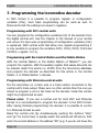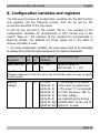
1
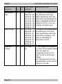
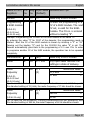
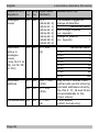
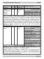
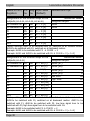
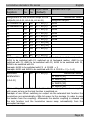
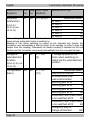
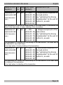
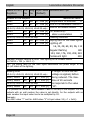
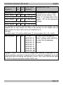
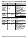
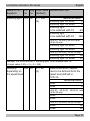
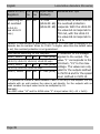
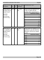
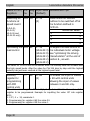
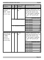
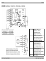
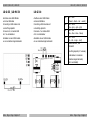
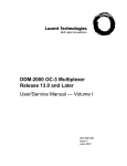
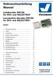
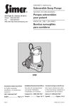
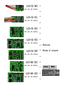
LD-G-30
n
Art.-Nr. 41-0130x
n
LD-G-31
n
Art.-Nr. 41-0131x
n
LD-G-32
n
Art.-Nr. 41-0132x
n
LD-G-33
n
Art.-Nr. 41-0133x
LD-G-34
n
Manual
n
Mode d´emploi
Art.-Nr. 41-0134x
n
LD-W-32
n
Art.-Nr. 41-0232x
n
LD-W-33
n
Art.-Nr. 41-0233x
n
DCC
MM
n
n
n
n
English
3
n
Français
47
n
n
© 09/2009 Tams Elektronik GmbH
All rights reserved. No part of this
publication may be reproduced or
transmitted in any form or by any
means, electronic or mechanical,
including photocopying, without prior
permission in writing from Tams
Elektronik GmbH.
Subject to technical modification.
© 09/2009 Tams Elektronik GmbH
Tout droits réservés, en particulier les
droits de reproduction et de diffusion
ainsi que le traduction. Toute duplication
ou reproduction sous quelque forme que
ce soit nécessite l´accord écrit de la
societé Tams Elektronik GmbH.
Sous réserve de modifications
techniques.
n
n
n
n
n
n
n
n
n
Locomotive decoders 30s series
English
Table of contents
1. Getting started
4
2. Safety instructions
6
3. Safe and correct soldering
8
4. Operation overview
9
5. Technical specifications
16
6. Mounting the locomotive decoder
17
7. Programming the locomotive decoder
22
8. Configuration variables and the registers
25
9. Check list for trouble shooting
43
10. CE and Warranty
44
Connection diagramms
LD-G-30
LD-G-31
I
II
LD-G-32 / LD-W-32
III
LD-G-33 / LD-W-33
IV
LD-G-34
Connection of a SUSI-module
V
VI
(Pages I to VI in the centre of this handbook are removeable.)
Remark: RailCom® is the registered trademark of the Lenz Elektronik
GmbH, Hüttenbergstraße 29, D-35398 Gießen. To increase the text´s
readabiliy we have refrained from refering to this point in each
instance.
Page 3
English
Locomotive decoders 30s series
1. Getting started
This manual applies to all locomotive decoders of the 30s series, so for:
§ locomotive decoder LD-G-30, LD-G-31, LD-G-32, LD-G-33 and
LD-G-34 and
§ locomotive decoder LD-W-32 and LD-W-33.
Provided there are no other details given for particular sections, the
information given applies to all decoders.
How to use this manual
This manual gives step-by-step instructions for safe and correct fitting
of the decoder, and operation. Before you start, we advise you to read
the whole manual, particularly the chapter on safety instructions and
the FAQ chapter. You will then know where to take care and how to
prevent mistakes which take a lot of effort to correct.
Keep this manual safely so that you can solve problems in the future. If
you pass the decoder on to another person, please pass on the manual
with it.
Intended use
The locomotive decoders of the 30er series are designed for mounting
in model locomotives with DC motor (LD-G-decoders) resp. AC motor
(LD-W-decoders). They evaluate the Motorola or DCC format data sent
by the digital central unit to their addresses and control the
locomotive´s motors and additional functions.
The decoders should not be mounted by children under the age of 14.
Reading, understanding and following the instructions in this manual
are mandatory for the user.
Any other use is inappropriate and invalidates any guarantees.
Page 4
Locomotive decoders 30s series
!
English
Caution:
Integrated circuits (ICs) are inserted on the decoder. They are sensitive
to static electricity. Do not touch components without first discharging
yourself. Touching a radiator or other grounded metal part will
discharge you.
Checking the package contents
Check the contents of the package for completeness after unpacking:
§ one decoder, with or without soldered connecting wires resp.
soldered NEM or PluX interface connector, depending on the
version,
§ one manual.
N.B. For technical reasons it is possible that the PCB is not completely
inserted. This is not a fault.
Required tools and materials
Make sure you have the following tools and materials ready for use, if
you have purchased a decoder without soldered interface connector:
§
§
§
§
§
§
an electronic soldering iron (max. 30 Watt) with a fine tip,
a soldering iron stand,
a tip-cleaning sponge,
a heat-resistant mat,
a small side cutter, a wire stripper and a pair of tweezers,
tin solder (0,5 mm. diameter),
In order to connect decoders without soldered connecting wires or
connectors you will need wire. Recommended cross sections:
§ > 0,05 mm² for connections to the function outputs
§ > 0,05 mm² for connections to the motor (except for the LD-G-34)
§ > 0,14 mm² for connections to the motor of the locomotive
decoder LD-G-34
Page 5
English
Locomotive decoders 30s series
2. Safety instructions
Mechanical hazards
Cut wires can have sharp ends and can cause serious injuries. Watch
out for sharp edges when you pick up the PCB.
Visibly damaged parts can cause unpredictable danger. Do not use
damaged parts: recycle and replace them with new ones.
Electrical hazards
§
§
§
§
§
§
Touching powered, live components,
touching conducting components which are live due to malfunction,
short circuits,
connecting the circuit to another voltage than specified,
impermissibly high humidity,
condensation build up
can cause serious injury due to electrical shock. Take the following
precautions to prevent this danger:
§ Never perform wiring on a powered decoder.
§ Mounting the decoder should only be done in closed, clean, dry
rooms. Beware of humidity.
§ Only use low power for this decoder as described in this manual
and only use certified transformers.
§ Connect transformers and soldering irons only in approved mains
sockets installed by an authorised electrician.
§ Observe cable diameter requirements.
§ After condensation build up, allow a minimum of 2 hours for dispersion.
§ Use only original spare parts if you have to repair the decoder.
Page 6
Locomotive decoders 30s series
English
Fire risk
Touching flammable material with a hot soldering iron can cause fire,
which can result in injury or death through burns or suffocation.
Connect your soldering iron or soldering station only when actually
needed. Always keep the soldering iron away from inflammable
materials. Use a suitable soldering iron stand. Never leave a hot
soldering iron or station unattended.
Thermal danger
A hot soldering iron or liquid solder accidentally touching your skin can
cause skin burns. As a precaution:
§
§
§
§
use a heat-resistant mat during soldering,
always put the hot soldering iron in the soldering iron stand,
point the soldering iron tip carefully when soldering, and
remove liquid solder with a thick wet rag or wet sponge from the
soldering tip.
Dangerous environments
A working area that is too small or cramped is unsuitable and can cause
accidents, fires and injury. Prevent this by working in a clean, dry room
with enough freedom of movement.
Other dangers
Children can cause any of the accidents mentioned above because they
are inattentive and not responsible enough. Children under the age of
14 should not be allowed to work with this decoder.
Little children can swallow small components with sharp edges, with
fatal results! Do not allow components to reach small children.
In schools, training centres, clubs and workshops, assembly, mounting
and operation must be supervised by qualified personnel.
In industrial institutions, health and safety regulations applying to
electronic work must be adhered to.
Page 7
English
Locomotive decoders 30s series
3. Safe and correct soldering
Caution:
Incorrect soldering can cause dangers through fires and heat. Avoid
these dangers by reading and following the directions given in the
chapter Safety instructions.
§ Use a small soldering iron with max. 30 Watt. Keep the soldering tip
§
§
§
§
§
§
§
clean so the heat of the soldering iron is applied to the solder point
effectively.
Only use electronic tin solder with flux.
When soldering electronic circuits never use soldering-water or
soldering grease. They contain acids that can corrode components
and copper tracks.
Solder quickly: holding the iron on the joints longer than necessary
can destroy components and can damage copper tracks or
soldering eyes.
Apply the soldering tip to the soldering spot in such a way that the wire
and the soldering eye are heated at the same time. Simultaneously add
solder (not too much). As soon as the solder becomes liquid take it
away. Hold the soldering tip at the spot for a few seconds so that the
solder flows into the joint, then remove the soldering iron.
The joint should be held still for about 5 seconds after soldering.
To make a good soldering joint you should use a clean and
unoxidised soldering tip. Clean the soldering tip with a damp piece
of cloth, a damp sponge or a piece of silicon cloth.
After soldering check (preferably with a magnifying glass) tracks for
accidental solder bridges and short circuits. This would cause faulty
operation or, in the worst case, permanent damage. You can
remove excess solder by putting a clean soldering tip on the spot.
The solder will become liquid again and flow from the soldering
spot to the soldering tip.
Page 8
Locomotive decoders 30s series
English
4. Operation overview
Driving in digital operation
The locomotive decoders of the 30´s series are multiple protocol
decoders, that can operate with and automatically recognise both DCC
or Motorola formats.
The number of addresses is dependant on the format being used.
Motorola-Format: 255 addresses.
DCC- Format: 127 Basis-addresses or 10.239 extended addresses.
In the DCC format the decoders can be driven in all speed levels (14,
28 or 128).
In the Motorola format the decoders can be driven in 14 or 27 speed
levels. Driving all 27 speed levels can be done only with central units which
support this mode (e.g. MasterControl). With central units which allow 14
speed levels only, it is only possible to select every second speed level.
Programming the decoders is done in DCC format by setting the
configuration variables and in Motorola format through the registers.
Operation in analogue mode
The locomotive decoders of the 30´s series can also be used in analogue
model railway layouts. They can be run with an A.C. speed control as well
as with a D.C. speed control. When putting the vehicle on the rails the
decoder recognizes automatically if it is run in analogue or digital mode
and sets the corresponding operation mode. The automatic recognition of
the analogue mode can be switched off.
!
Caution:
Old analogue driving transformers (e.g. models in a blue housing from
Märklin**) are not suitable for use with digital decoders in analogue
operation! These transformers have been designed for the older supply
voltage of 220 V and, due to construction, generate very high excess
voltage impulses when changing the driving direction. When using them
Page 9
English
Locomotive decoders 30s series
with the modern supply voltage of 230 V too high excess voltage impulses
can occur, damaging electronic parts on the decoder. For that reason only
use driving transformers designed for a net voltage of 230 V.
Switching the function outputs on or off is not possible in analogue
mode. They can be programmed so that they are either switched on or
off in analogue mode. The effects set for the outputs are active in
analogue mode as well.
Outputs to be switched with F0 are switched on or off in analogue
mode according to the direction of travel.
For LD-G-33 and LD-G-34 only: The decoders´ load control is also
active in analogue mode. The set maximum speed also limits in
analogue mode the maximum speed of the locomotive.
LD-G-30, LD-G-33, LD-G-34: Overload Protection
As soon as the maximum total current of the LD-G-30, LD-G-33 or LDG-34 is exceeded, the decoder automatically temporally switches off the
motor and the function outputs, in order to protect the decoder from
overheating.This operation will be repeated until the overload has been
eliminated. With the LD-G-30 and the LD-G-33 the sensivity of the
overload protection can be altered by programming a configuration
variable.
!
Caution:
When a short circuit caused by contact between decoder and housing
occurs the current as a rule is so high, that the overload protection
cannot protect the decoder from being damaged.
Page 10
Locomotive decoders 30s series
English
Driving of the motor
The differernt decoder types are designed to optimally control their
particular fitting motor types.
Decodertyp
PWM
LD-G-30
LD-G-31
LD-G-32
LD-G-33
LD-G-34
LD-W-32
LD-W-33
32 kHz (fixed)
17 or 32 kHz (to be set)
32 kHz (fixed)
17 or 32 kHz (to be set)
17 or 32 kHz (to be set)
480 or 60 Hz (to be set)
480 Hz (fixed)
Suitable for coreless
(Faulhaber) motors
yes
yes
yes
yes
yes
no
no
LD-G-decoders: Load control
The LD-G-locomotive decoders for DC motors have a load control, the
decoder LD-W-locomotive decoders for AC motors do not have this
function. The load control influences the motor voltage to keep the
locomotive at constant velocity, independent of additional loads (e.g.
running up a gradient, coupled carriages).
It is possible to switch on and off the load control by varying a CV-variable
of the deocder. The parameters of the load control may be altered as well,
in order to adapt the decoder to the motor´s individual characteristics.
Parameters of the load control: The load control is determined by
three parameters which have to be coordinated in order to achieve
optimal driving characteristics. Each of the load control parameters is
assigned to a configuration variable. The parameters are:
KP: The proportional component of the load control ensures the
difference between the set and the present value being as small as
possible. It cannot have the value "0" at any time. This component
affects the basic speed. In case the set value is too small the
locomotive runs too slowly. In case the set value is too high the
locomotive vibrates while moving.
Page 11
English
Locomotive decoders 30s series
KI: The integral component of the load control ensures the remaining
difference between the set and the present value is reduced to 0 and so
for the correction of very small divergences. If the set value is too high
the locomotive vibrates massively while moving.
KD: The differential component of the load control ensures that the control
is not converted too quickly. Is the set value to low then the locomotive
vibrates. If the set value is too high, the locomotive shakes while moving.
Velocity characteristic
The decoders can be adjusted to the driving characteristics of the
motor and the characteristic speed of the locomotive type, by setting the
starting velocity and the maximum velocity. From the starting velocity and
the maximum velocity the decoder generates a linear velocity characteristic.
When the speed level mode is set to 28 speed levels, it is possible to
assign any motor voltage to all of the 28 speed levels as an alternative
to the linear velocity characteristic. This allows the programming of a
velocity characteristic which adjusts the individual driving characteristics
of the motor. The set values are saved in the alternative velocity table.
Shunting gear
It is possible to switch into the shunting gear mode via a function key,
when so programmed. In the shunting gear mode, the velocity of all
speed levels is reduced to approx. 50 % compared to the set velocity.
Acceleration and brake delay
It is possible to program the acceleration and brake delay individually
via the central unit. When so programmed, it can be switched on and off
with the function key F3.
Emergency stop
It is possible to carry out an emergeny stop at a change of direction
automatically, when so programmed.
Page 12
Locomotive decoders 30s series
English
LD-G-33, LD-G-34 and LD-W-33: Slider commutation
The decoders LD-G-33, LD-G-34 and LD-W-33 have a function output to
be programmed so that it switches a relay for slider commutation. Due
to the principle of the slider commutation it does not work in sections
switched currentless (braking sections).
Function outputs
The decoders have two, four or six function outputs depending on the
type, which are available to connect optional accessories (e.g. lighting,
smoke generator, sound module, electric coupling). The accessories´
number and type to be connected depends on the outputs´number and
maximum current as well as on the maximum total current of the special
decoder (see section 5 "Technical specifications").
In DCC format the function outputs can be switched via the function keys
F0 to F12. In Motorola format the function outputs can be switched via
the function keys F0 to F4. The functions F5 to F9 can be switched via the
function keys F1 to F4 and F0 by assigning them to a second address.
The functions F10 to F12 are not available in Motorola format.
You can assign the function keys to the function outputs freely. It is
possible to assign several function keys to one function output.
LD-G-31: Connections for a signal hooter
It is possible to connect a loudspeaker to the LD-G-31 (not included in
the package). Via two function keys two signal hooters with different
frequencies can be generated. You can assign the function keys freely.
LD-G-33, LD-G-34 and LD-W-33: SUSI interface
A SUSI module can be connected to the LD-G-33, LD-G-34 or the
LD-W-33 and programmed via the decoder. It is not possible to read
the SUSI module´s data via the decoder.
The locomotive decoder transmits the function status and the speed
level set at the central unit, to the SUSI module. This affects the SUSI
module´s outputs depending on the speed level (e.g. motor sound).
Page 13
English
Locomotive decoders 30s series
Effects of the function outputs
It is possible to set the following effects for all function outputs individually:
Dimming: The voltage applied to an output can be reduced by
programming the decoder accordingly. Example of use: The electric
bulbs of older vehicles made for analogue operation can be dimmed
and thus must not be exchanged after the mounting of the decoder. In
addition, it is possible to dim the voltage depending on the speed level.
This enables weak smoke generation during halts or a switched off or
dimmed cab lighting while the train is moving.
Flashing. Both the frequency and the keying ratio can be set. Examples
of use: single and alternating flash lights or strobe lights.
Switching on and off depending on the direction of travel: Any
output can be programmed to be switched on and off depending on the
direction of travel.
LD-G-31, LD-G-33, LD-G-34 and LD-W-33 only: Kick function: It
is possible to set the function outputs so that they get the full voltage
first for up to 20 seconds and then are dimmed. Example of use: For
some types of electric couplings you need the full voltage for
decoupling and the voltage then reduced to protect the couplings. In
addition it is possible to program the outputs so that the locomotive
moves a short distance from the disengaged carriages automatically
after releasing the kick function.
LD-G-31, LD-G-33, LD-G-34 and LD-W-33 only: Special function
for speed level 0: It is possible to program one function to switch off
other functions or switch on special function outputs at speed level 0.
Example of use: In some locomotive sheds it is customary that the tail
lamps of parked locomotives have to be temporally set at the front and
the back.
Page 14
Locomotive decoders 30s series
English
Feedback with RailCom
RailCom is a log for bi-directional communication in digital model
railway layouts controlled in DCC-format. It allows e.g. the feedback of
the address and the CV values from the decoder to the digital control
unit or to special receivers (so-called detectors). The decoders must be
designed to send the RailCom messages.
When so programmed, the locomotive decoders of the 30´s series send
(continuously) the (basic, extended or consist) address to the detectors (socalled RailCom broadcast datagramm) and transfer a CV message after a
DCC CV read-out command.
Sending RailCom messages is only possible in layouts with a DCC signal on
the rails. That is the reason why it is not possible to use the RailComfunction in a pure Motorola environment, but only when at least one other
locomotive or function decoder on the layout is controlled in DCC format.
Page 15
English
Locomotive decoders 30s series
5. Technical specifications
Data format
Feedback log
Supply voltage
DCC and Motorola
RailCom
12-24 Volt digital voltage
or max. 16 V analogue voltage
Current consumption
(without connected loads)
Protected to
Ambient temperature in use
Ambient temperature in storage
Comparative humidity allowed
Max. current
for motor [mA]
Number of
function outputs
Max. current
per putput [mA]
700
1.200
1.500
1.500
3.000
1.500
1.500
500
500
1.000
1.000
3.000
1.000
1.000
2
4
2
6
6
2
6
100
300
300
500
500
300
500
Page 16
12,5 x 9,3 x 2,8
20 x 9,5 x 3,5
22 x 17 x 6
25,5 x 16 x 2,9
26,5 x 18 x 5,5
22 x 17 x 6
25,5 x 16 x 2,9
Weigt without cables
or interface [g]
Max. total current
[mA]
LD-G-30
LD-G-31
LD-G-32
LD-G-33
LD-G-34
LD-W-32
LD-W-33
Dimensions of PCB
approx. [mm]
Decoder type
approx. 10 mA
IP 00
0 - + 60° C
-10 - + 80° C
max. 85 %
0,2
0,3
1,8
1,6
2,4
1,8
1,6
Locomotive decoders 30s series
English
6. Mounting the locomotive decoder
!
Caution:
Before mounting the decoder check if the maximum locomotive
motor´s current on-load is below the maximum permissible value. If it
is above the decoder is not suitable for mounting in this locomotive. It
would be damaged when put into operation or with decoders with
overload protection (LD-G-30, LD-G-33 and LD-G-34) switched off.
LD-G-decoders: Using decoders with interface connectors
Many recent locomotives with d.c. motor are equipped ex works with an
interface socket according to NEM 651, NEM 652 or NEM 658. The
interface enables you to connect the motor to the motor, the rail
current collectors, the lighting and – provided the special connector is
designed for it – additional accessories.
Using a decoder with a suitable connector saves separating the
connections and soldering works at the locomotive. When mounting
decoders with 6-pole interface connectors according to NEM 651 or 8pole interface connectors according to NEM 652, take care to put the
markings on the connector and on the socket on top of each other. The
12-pole PluX-connectors according to NEM 658 can be mounted in one
direction only.
Mounting decoders without interface connector
Open the locomotive housing. Locate the position for the decoder.
Disconnect the motor from the rail current collector or the change-over
switch from the motor and rails if you have a locomotive with electronic
change-over switch. The change-over switch is no longer necessary,
you can remove it.
!!
Caution:
The interference suppression devices mounted to the motor or the
connecting wire must not be removed! Motor and interference
Page 17
English
Locomotive decoders 30s series
suppression devices are one unit. If even one part is removed, it can
cause extreme interference!
Connecting the decoder
Follow the connection diagram for the particular decoder.
Decoder for DC motors (LD-G-decoder): Connect the decoder to the
rail current collectors and to the motor.
Decoder for AC motors (LD-W-decoder): Connect the decoder to the
connections from the slider and the housing. These two connections
can be exchanged without effecting functionality. Next connect the
connections of the field coil and the connection of the motor shield to
the decoder.
Should the locomotive´s direction of motion in analogue mode not
match the direction of motion set at the speed control you have to
swap the connections to the rail current collectors / the slider.
Connecting accessories to the outputs
Before connecting the lighting and other accessories to the outputs
check if the output´s current is below the maximum permissible value
and the total current is below the safe load (including motor current).
!
Caution:
Should the permissible output current is exceeded, this normally results
in permanent damage to the output. Exceeding the decoder´s total
current will lead to damage or, with decoders with overload protection
(LD-G-30, LD-G-33 and LD-G-34) to switching off the decoder.
Disconnect any existing diodes in the leads to the lamps. Connect the
lamps and the accessories to the function outputs of the decoder. The
assignment of the function outputs to the function keys will be made
when programming the decoder.
Page 18
Locomotive decoders 30s series
English
If the lamp or the accessory is already connected with one side to
vehicle ground, the connection is complete. If not, connect the second
side of the lamp or the accessory to the return conductor of the
decoder (point RL).
!
Caution:
If you connect the accessories to the return conductor for all functions
(point RL), the accessories must be insulated. The accessories should
not make contact with metal parts of the vehicle. Possible short circuit!
The decoder will be damaged in operation. The overload protection of
the decoders LD-G-30, LD-G-33 and LD-G-34 cannot protect them from
being so damaged.
!!
Caution:
The return conductor for all functions (point RL) must under no
circumstances be connected to vehicle ground. Possible short circuit!
The decoder will be damaged in operation. The overload protection of
the decoders LD-G-30, LD-G-33 and LD-G-34 cannot protect them from
being so damaged.
Tip: Before starting to program the locomotive decoder you should
connect the motor to the decoder. Otherwise there is no confirmation
signal to the (DCC-) central unit. Should you intend to program the
decoder with a Motorola central unit you should always connect the
lighting to the outputs, intended to connect the front and the back
lighting ex works. The locomotive indicates the change-over to the
programming mode and the taking-over of settings by flashing of the
lighting connected to these outputs.
Page 19
English
Locomotive decoders 30s series
Connecting the LEDs
The function outputs of the decoder switch respective to the decoder
ground. For that reason you must connect the cathode (-) of the LED to
the function outputs.
!
Caution:
If you use light-emitting diodes (LEDs) you must always operate them via a
series resistor. LEDs are available in many different models. The series
resistor limits the current flow of the LED and will need to be calculated for
each model. Ask for the max. current rating when buying your LEDs.
You can connect several LEDs in parallel to each output. In this case
every LED must have a series resistor of its own. If you connect several
LEDs to one output in series, only one series resistor is needed.
LD-G-31: Connecting a loudspeaker
Use a loudspeaker as large as possible with an impedance of at least
8 Ohm. Decisive for the sound reproduction is the correct mounting of
the loudspeaker. The loudspeaker membrane should emit directly to the
outside, the other side into the inside of the vehicle which should be as
airtight as possible. If necessary, use a loudspeaker with a sound
cartridge. The larger the volume in the inside, the better is the
reproduction quality. Suitable for the mounting are e.g. the bottom of
the vehicle or the back of the driver´s cab.
Connect the loudspeaker to the points X1 and X2 of the decoder.
LD-G-33, LD-G-34 und LD-W-33: Connecting a SUSI module
The decoder has four soldering points for the connection of a SUSI
module. You will find the pin connection in the connection diagram for
the particular decoder.
Page 20
Locomotive decoders 30s series
English
Connecting a smoothing capacitor
In track sections with bad contacts the power supply may be
interrupted shortly. With those locomotive decoders with enough space
on the PCB (LD-G-32, LD-G-33, LD-G-34, LD-W-32, LD-W-33) you can
solder an additional capacitor to counteract this effect (see connection
diagram of the particular decoder).
Fixing the locomotive decoder
After completing all connections fix the locomotive decoder with doublesided adhesive tape, for example.
AUX2
----AUX2 AUX3 AUX4
AUX2 AUX3 AUX4
AUX2
----AUX2 AUX3 AUX4
signal horn
low (X1)
Accessory
switched via F6
--signal horn
high (X2)
Accessory
switched via F5
switched via F4
AUX1
AUX1
AUX1
AUX1
AUX1
--Acceleration and braking
declay on / off
LD-G-32
LD-G-33
LD-G-34
LD-W-32
LD-W-33
switched via F3
AUX1 AUX2
----AUX1 AUX2 AUX3 AUX4
(X7) (X8) (X3) (X6)
Shunting gear on / off
Accessory
switched via F2
Front lighting
LD-G-30
LD-G-31
Back lighting
Decoder type
Accessory
switched via F1
Decoder factory settings
----AUX5 AUX6
AUX5 AUX6
----AUX5 AUX6
If you want to use the decoder factory settings, you have to connect
the lighting and the accessories according to the details in the list.
Page 21
English
Locomotive decoders 30s series
7. Programming the locomotive decoder
In DCC format it is possible to program register or configuration
variables (CVs), main track programming can be used as well. In
Motorola format the settings are saved in registers.
Programming with DCC central units
You can programm the configuration variables (CV) of the decoder from
the digital central unit. See the chapter in the manual of your central
unit where the byte wise programming of configuration variables (CVs)
is explained. With central units that allow only register-programming it
is only possible to program the variables CV#1, CV#2, CV#3, CV#4 and
CV#29 (= register 1 to 5).
Programming with the Central Station and the Mobile Station
With the Central Station or the Mobile Station of Märklin** you can
program the registers. With the auxillary register #62 values above 80 can
be entered. Select the article no. 29750 from the locomotive database
and program the decoder as described for this article in the Central
Station´s or Mobile Station´s manual.
Programming with Motorola central units
Put the locomotive on a track oval or a track section connected to the
central unit’s track output. Make sure no other vehicle than the one you
intend to program is set on the track as the decoder inside this vehicle
might be programmed as well.
Please note: If you use a central unit for both DCC and Motorola
format it is recommended to program the decoder in the DCC format.
After having finished programming the decoder it is possible to control
it in Motorola format as well.
Reset the central unit (by simultaneously pushing the buttons "stop"
and "go" for some time) or quickly switch the central unit off and on. First
enter the current address or the address "80" (e.g. if you do not know the
Page 22
Locomotive decoders 30s series
English
current address). Manufacturers setting is "3". Set all functions (function,
f1 to f4) to "off".
Push the "stop" button at the central unit. Next, operate the direction
switch and hold it in that position while briefly pushing the "go" button.
As soon as the lamps connected to the outputs AUX1 or AUX2 flash
(after approx. 2 seconds) the decoder is in the programming mode and
you can release the direction switch.
Starting the programming mode
Switch on the central unit or
perform a reset at the central unit.
Set the current address or address 80.
Set all functions to "off".
Push button „stop“
à Switch off the track voltage.
Operate the direction switch and hold it in
that position. Briefly push the button „go“.
As soon as the lighting flashes,
release the direction switch.
Start register-programming
(lighting flashes)
Page 23
English
Locomotive decoders 30s series
After having started the programming mode (and when the
locomotive´s lighting flashes) you can program the decoder´s registers
as follows:
1. Choose the register you want to programm by setting the register´s
number like a Motorola locomotive address at your central unit.
Please note that with some central units a leading "0" has to be
entered.
2. Operate the direction switch. The lighting flashes faster.
3. Set the desired value of the register by setting the register´s value
as Motorola locomotive address at your central unit.
4. Operate the direction switch again. The lighting starts flashing
again.
Repeat the steps 1 to 4 for all registers you want to program. In order
to choose a register for programming or to enter a value for a register
you have to confirm the entered number like selecting a Motorola
locomotive address. The lighting shows which kind of entry the decoder
expects:
§ lighting flashes à entry of a CV´s number
§ lighting flashes faster à entry of a CV´s value
In order to stop the programming mode push "stop".
Programming with the CV-Navi
Instead of programming the configuration variables or registers of the
decoder using the digital central unit, you can use the free software CVNavi. You will find the free download under:
www.tams-online.de
Page 24
Locomotive decoders 30s series
English
8. Configuration variables and registers
The following list shows all configuration variables (for the DCC format)
and registers (for the Motorola format), that can be set for the
locomotive decoders of the 30s series.
In the list you will find in the column "CV-no." the numbers of the
configuration variables for programming in DCC format and in the
column "Reg.-no." the numbers of the registers for programming in
Motorola format. The defaults are those values set in the state of
delivery and after a reset.
* For some configuration variables, the input values have to be calculated
by adding the numerical values assigned to the desired parameters.
Name of CVs / CV- Reg. Input value
Registers
no. no. (Default)
Remarks and Tips
Basic address
Range of values in
DCC-Format: 1 ... 127
1
01
1 ... 255
(3)
Tip: If a value higher than 127 is set for the basic address and the use of
extended addresses in CV#29 is set to off, the decoder does not react to signals
in DCC format!
Starting
voltage
2
47
0 ... 255
(LD-G-30 : 5)
(LD-G-31 : 5)
(LD-G-32 : 5)
(LD-G-33 : 5)
(LD-G-34 : 5)
(LD-W-32: 50)
(LD-W-33: 60)
= The voltage to be output
to the motor at speed level
1. The value "0" corresponds
to 0 Volt, the value "255" to
the max. voltage.
See "optimizing the driving
characteristics" at the end of
section 8., as well.
Page 25
English
Locomotive decoders 30s series
Name of CVs / CV- Reg. Input value
Registers
no. no. (Default)
Remarks and Tips
Acceleration
rate
3
44
= Length of the delay before
the switching to the next
higher speed level when the
locomotive is accelerating.The
delay is calculated as follows:
(value of CV#3) x 0,9 sec. /
number of speed levels
Braking rate
4
45
0 ... 255
(LD-G-30 : 20)
(LD-G-31 : 16)
(LD-G-32 : 20)
(LD-G-33 : 16)
(LD-G-34 : 16)
(LD-W-32: 16)
(LD-W-33: 10)
0 ... 255
(LD-G-30 : 15)
(LD-G-31 : 8)
(LD-G-32 : 15)
(LD-G-33 : 8)
(LD-G-34 : 8)
(LD-W-32: 5)
(LD-W-33: 5)
Maximum
voltage
5
46
0 ... 255
(0)
= The voltage to be output to
the motor at the highest speed
level. The value "2"
corresponds to 0,8 %, the
"255" to 100 % of the max.
voltage.
See "optimizing the driving
characteristics" at the end of
section 8., as well.
Page 26
= Length of the delay before
the switching to the next
lower speed level when the
locomotive is braking. The
delay is calculated as
described in CV#3.
Locomotive decoders 30s series
English
Name of CVs / CV- Reg. Input value Remarks and Tips
Registers
no. no. (Default)
Version
7
---
---
Read only in DCC format!
Programming 7
a SUSI module
02
9
To start the programming of a
CV of a SUSI module. The next
CV set, is valid for the SUSImodule. The CV-no. is entered
without a leading "9".
(LD-G-33,
LD-G-34 and
LD-W-33 only)
Example: Programming the CV#902 of the SUSI module to the value "8":
By entering the value "9" for CV#7 of the decoder, the programming mode is
started. Next the CV of the SUSI module is chosen by entering a "2" or "02"
(leaving out the leading "9") and for the CV#902 the value "8" is set. The
decoder automatically goes back to the programming of it´s own CVs. In order
to programm another CV of the SUSI module, the operation has to be repeated
completely.
Manufacturer
8
---
(62)
Read only in DCC format!
Reset
8
03
0 ... 255
Any input value restores the
settings in state of delivery.
Motor
frequency
9
48
0, 1
(0)
31,5 kHz
17 kHz
Numerical value*
0
1
480 Hz
60 Hz
Numerical value*
0
1
(LD-G-31,
LD-G-33 and
LD-G-34 only)
Tip: In case that the locomotive´s driving characteristics are not satisfactory with
the standard setting of 31,5 kHz, the motor frequency of 17 kHz should be chosen.
Motor
frequency
9
48
0, 1
(0)
(LD-W-32 only)
Tip: In case that the locomotive´s driving characteristics are not satisfactory with
the standard setting of 480 Hz, the motor frequency of 60 Hz should be chosen.
Page 27
English
Locomotive decoders 30s series
Name of CVs / CV- Reg. Input value
Registers
no. no. (Default)
Remarks and Tips
Analogue
mode
= procedure triggers a
change of direction
Numerical value*
Overvoltage impulse
(a.c. layouts)
0
Change of polarity
(d.c. layouts)
1
12
06
0, 1
(LD-G-30 : 0)
(LD-G-31 : 1)
(LD-G-32 : 0)
(LD-G-33 : 0)
(LD-G-34 : 0)
(LD-W-32: 0)
(LD-W-33: 0)
Functions
13
active in
analogue
mode
(only for F1 to
F8, not for F9
to F12)
41
0 ... 255
(0)
Extended
address
17
04
192 ... 255
(192)
18
05
0 ... 255
(255)
Consistadresse 19
53
1 ... 127
(0)
Page 28
F1
F2
F3
F4
F5
F6
F7
F8
on
on
on
on
on
on
on
on
Numerical value*
1
2
4
8
16
32
64
128
Only for DCC format. Most
central units permit entering
extended addresses directly.
The CVs # 17, 18 and 29 are
set automatically to the
proper values.
= 2nd adress
In DCC format only!
Locomotive decoders 30s series
English
Name of CVs / CV- Reg. Input value Remarks and Tips
Registers
no. no. (Default)
Braking
performance
with d.c.
voltage
27
49
0, 16, 32,
48
(0)
Numerical value*
No braking with d.c. voltage 0
Braking with posit. d.c. volt. 16
Braking with negat. d.c. volt. 32
Tip: It is standard to switch over into analogue mode when applying a d.c.
voltage at the rails. In case that the decoder is run in a layout with a braking
route based on applying a d.c. voltage (e.g. Märklin**-braking route), the
locomotive has to be prevented from changing over into analogue mode and it
has to be ensured that the locomotive reacts as expected on the braking route.
When braking with positive or negative d.c. voltage is set for the decoder, the
analogue recognition is switched off automatically. The setting of the negative or
positive d.c. voltage is related to the right rail, as seen in the locomotive´s
direction of motion.
Configuration
data 1
29
07
0 ... 64
(14)
Numerical value*
Direction "Standard"
0
Reverse direction
1
14 speed levels
0
28 or 128 speed levels
2
Analoge recognition off
0
Analoge recognition on
4
RailCom off
0
RailCom on
8
Linear velocity characteristic 0
Alternat. velocity charact. 16
Basic addresses
0
Not for MM mode: Extended addresses
32
Example: CV#29 = 0. à Direction = "Standard". 14 speed levels. RailCom = "off".
Automatic analogue recognition = "off". Basic addresses.
Example: CV#29 = 46. à Direction = "Standard". 28 or 128 speed levels in DCCmode. Automatic analogue recognition = "on". RailCom = "on". Extended addresses.
Tip: If the use of extended addresses is activated in CV#29, the decoder does
not react to signals in Motorola format!
Page 29
English
Locomotive decoders 30s series
Name of CVs / CV- Reg. Input value
Registers
no. no. (Default)
Remarks and Tips
Assignment of the function keys to the
outputs (LD-G-30, LD-G-32, LD-W-32)
F0 forward on 33 08 0 ... 3 (1)
F0 backward on 34 09 0 ... 3 (2)
F1
35 10 0 ... 3 (0)
F2
36 11 0 ... 3 (0)
F3
37 12 0 ... 3 (0)
...
...
...
F12
46 21 0 ... 3 (0)
Numerical value*
Assigned output:
AUX1
1
AUX2
2
Factory settings: AUX1 to be switched with F0, switched on at forward motion.
AUX2 to be switched with F0, switched on at backward motion.
Example: AUX2 to be switched with F5 à CV#39 = 2
Example: AUX1 and AUX2 to be switched with F6 à CV#40 = 3 (= 1+2)
Assignment of the function keys to the
outputs (LD-G-31)
F0 forward on 33 08 0 ... 63 (1)
F0 backward on 34 09 0 ... 63 (2)
F1
35
10
0 ... 63 (4)
F2
36
37
38
39
40
41
...
46
11
12
13
14
15
16
...
21
0
0
0
0
0
0
F3
F4
F5
F6
F7
...
F12
...
...
...
...
...
...
63 (8)
63 (0)
63 (0)
63 (16)
63 (32)
63 (0)
Numerical value*
Assigned output:
AUX1 (X7)
1
AUX2 (X8)
2
AUX3 (X3)
4
AUX4 (X4)
8
low tone
16
high tone
32
0 ... 63 (0)
Factory settings: AUX1 to be switched with F0, switched on at forward motion.
AUX2 to be switched with F0, switched on at backward motion. AUX3 to be
switched with F1, AUX4 to be switched with F2, low tone signal horn to be
switched with F5, high tone signal horn to be switched with F6.
Example: AUX2 to be switched with F5 à CV#39 = 2
Example: AUX1 and AUX2 to be switched with F6 à CV#40 = 3 (= 1+2)
Page 30
Locomotive decoders 30s series
English
Name of CVs / CV- Reg. Input value
Registers
no. no. (Default)
Remarks and Tips
Assignment of the function keys to the
outputs (LD-G-33, LD-G-34, LD-W-33)
F0 forward on 33 08 0 ... 63 (1)
F0 backward on 34 09 0 ... 63 (2)
F1
35 10 0 ... 63 (4)
F2
36 11 0 ... 63 (8)
F3
37 12 0 ... 63 (0)
F4
38 13 0 ... 63 (0)
F5
39 14 0 ... 63 (16)
F6
40 15 0 ... 63 (32)
F7
41 16 0 ... 63 (0)
...
...
...
F12
46 21 0 ... 63 (0)
Numerical value*
Assigned output:
AUX1
1
AUX2
2
AUX3
4
AUX4
8
AUX5
16
AUX6
32
Factory settings: AUX1 to be switched with F0, switched on at forward motion.
AUX2 to be switched with F0, switched on at backward motion. AUX3 to be
switched with F1, AUX4 to be switched with F2, AUX5 to be switched with F5,
AUX6 to be switched with F6.
Example: AUX2 to be switched with F5 à CV#39 = 2
Example: AUX1 and AUX2 to be switched with F6 à CV#40 = 3 (= 1+2)
Extended
kickfunction
(LD-G-31)
47
50
0 ... 63 (0)
for
for
for
for
AUX1
AUX2
AUX3
AUX4
Numerical value*
(X7)
1
(X8)
2
(X3)
4
(X4)
8
When setting the extended kick function for an output, the motor is supplied
with power as long as the kick function is switched on.
Example of use: When switching an output via the extended kick function the
locomotive runs automatically a little bit nearer to the carriage (in order to ease
the burden from the coupling). Afterwards the electric coupling is released via
the kick function and the locomotive moves away automatically from the
uncoupled carriage.
Page 31
English
Locomotive decoders 30s series
Name of CVs / CV- Reg. Input value
Registers
no. no. (Default)
Extended
kickfunction
47
50
Remarks and Tips
0 ... 63 (0)
for
for
for
for
for
for
(LD-G-33,
LD-G-34 und
LD-W-33)
AUX
AUX
AUX
AUX
AUX
AUX
1
2
3
4
5
6
Numerical value*
1
2
4
8
16
32
When setting the extended kick function for an output, the motor is supplied with
power as long as the kick function is switched on.
Example of use: When switching an output via the extended kick function the
locomotive runs automatically a little bit nearer to the carriage (in order to ease the
burden from the coupling). Afterwards the electric coupling is released via the kick
function and the locomotive moves away automatically from the uncoupled carriage.
Voltage at
extended kick
function
48
51
0 ... 255
(0)
= voltage applied to the
motor when switching an
output via the extended kick
function.
49
22
0 ... 127
(73)
Numerical value*
Load control inactive
0
LD-G-decoders only:
Load control active
1
Shunting gear at F1
2
Shunting gear at F2
4
Shunting gear at F3
8
Shunting gear at F4
16
Acceleration and brake delay
to be switched at F3
32
Acceleration and brake delay
to be switched at F4
64
Emergency stop at
change of direction
128
(LD-G-31,-33,-34,
LD-W-33)
Configuration
data 2
Page 32
Locomotive decoders 30s series
English
Name of CVs / CV- Reg. Input value
Registers
no. no. (Default)
Remarks and Tips
Parameter of 50
load control KP
= Proportional component of
the load control.
See "optimizing the driving
characteristics" at the end of
section 8., as well.
23
(LD-G-decoders
only)
0 ... 255
(LD-G-30 : 40)
(LD-G-31 : 65)
(LD-G-32 : 90)
(LD-G-33 : 80)
(LD-G-34: 80)
The parameter KP defines the basic speed. A too small value à locomotive too
slow. A too high value à heavy shaking of the locomotive.
Parameter of 51
load control KI
24
(LD-G-decoders
only)
0 ... 255
(LD-G-30 : 30)
(LD-G-31 : 12)
(LD-G-32 : 70)
(LD-G-33 : 45)
(LD-G-34 : 45)
= Integral component of the
load control.
See "optimizing the driving
characteristics" at the end of
section 8., as well.
The parameter KT provides the fine tuning of the load control. The value has to
be adjusted in very small steps.
A too high value à heavy shaking of the locomotive.
Parameter of 52
load control KD
(LD-G-decoders
only)
25
0 ... 255
(LD-G-30 : 40)
(LD-G-31 : 40)
(LD-G-32 : 40)
(LD-G-33 : 50)
(LD-G-34 : 50)
= Differential component of
the load control.
See "optimizing the driving
characteristics" at the end of
section 8., as well.
The parameter KD retards the transforming of the load control. A too small value
à shaking of the locomotive.
A too high value à vibrating of the locomotive.
Page 33
English
Locomotive decoders 30s series
Name of CVs / CV- Reg. Input value Remarks and Tips
Registers
no. no. (Default)
Effects of the outputs
AUX1
53 26
AUX2
54 27
Numerical value*
0 ... 255 (0) Independent of direction
0
0 ... 255 (0) AUX off at backward motion 1
2
LD-G-31, LD-G-33, LD-G-34, LD-W-33 only: AUX off at forward motion
AUX3
55 28 0 ... 255 (0) For AUX6 only:
AUX4
56 29 0 ... 255 (0)
slider commutation
4
Flashing inverted
8
LD-G-33, LD-G-34, LD-W-33 only:
AUX5
57 30 0 ... 255 (0) Keying ratio of the flash lights:
AUX6
58 31 0 ... 255 (0) Lighting off
16, 32, 48, 64, 80, 96, 112
Regular flashing
128
144, 160, 176, 192, 208, 224
Permanent light
240
Example: Regular flashing at AUX1 and lighting off at forward motion
à CV#53 = 130 (= 128 + 2)
Tip: The keying ratio for the flash lights determines the phase length of the
on-/off states of the lighting.
Kicking time
LD-G-31, LD-G-33, LD-G-34, LD-W-33 only:
AUX1, AUX2
AUX3, AUX4
59
60
32
33
0 ... 255 (0)
0 ... 255 (0)
LD-G-33, LD-G-34, LD-W-33 only:
AUX5, AUX6
61
34
0 ... 255 (0)
= length of time the full
voltage is applied, before
being reduced. The max.
time of 20 seconds
corresponds to the value
"15".
It is possible to choose a value between 0 and 15 for any of the outputs. For the
outputs with an odd number the value is set directly, for the outputs with an
even number the input value has to be multiplied by 16.
Example:
For AUX3 value "7" and for AUX4 value "3"à Input value: 55 (=7 + 3x16)
Page 34
Locomotive decoders 30s series
Name of CVs / CV- Reg. Input value
Registers
no. no. (Default)
English
Remarks and Tips
Dimming of the outputs:
AUX1, AUX2
62 35
= Reduction of the voltage
1...255 (255) applied to the output. The
value "1" corresponds to the
LD-G-31, LD-G-33, LD-G-34, LD-W-33 only:
AUX3, AUX4
63 36 1...255 (255) lowest, "15" to the maximum
voltage.
LD-G-33, LD-G-34, LD-W-33 only:
AUX5, AUX6
64
37
1...255 (255)
It is possible to choose a value between 0 and 15 for any of the outputs. For the
outputs with an odd number the value is set directly, for the outputs with an
even number the input value has to be multiplied by 16.
Example:
For AUX5 value "14" and for AUX6 value "2"à input value: 46 (=14 + 2x16)
Starting-kick
65
60
0 ... 14
(LD-G-30 : 0)
(LD-G-31 : 2)
(LD-G-32 : 0)
(LD-G-33 : 0)
(LD-G-34 : 0)
(LD-W-32: 55)
(LD-W-33: 65)
= short-time increase of
motor voltage while starting
to clear the breakaway
torque.
Example: CV#65 = 6 à The motor voltage while starting is equivalent to the
voltage applied in operation at speed level 6. It is reduced immediately to the set
speed level with the braking rate defined in CV#4. Thus, when altering the value
for CV#4 it may be necessary to alter CV#65, too.
Page 35
English
Locomotive decoders 30s series
Name of CVs / CV- Reg. Input value Remarks and Tips
Registers
no. no. (Default)
Alternative
velocity
characteristic
(only with
mode 28
speed levels)
67
.
.
94
67
.
.
94
Flashing
frequency of
the lighting
112 38
0 ... 255
= The velocity table for the
alternative velocity
characteristic. Any motor
voltage can be assigned to all
of the 28 speed levels.
The value "0" corresponds to a
voltage of "0", "255" to the
maximum voltage.
10 ... 255
(200)
Settings common for all
lighting.
10
à lowest frequency
255
à highest frequency
Examples for the flashing frequency:
CV#112 = 10 à 0,125 Hz / CV#112 = 200 à 0,5 Hz
CV#112 = 230 à 1 Hz / CV#112 = 255 à 2,5 Hz
Internal
113 39
speed level for
CV#116
1 ... 126
(16)
= speed level, at which the
outputs defined in CV#116 are
dimmed.
2nd Motorola
address
1 ... 255
(4)
= Address needed to switch
additional functions in
Motorola format. The function
keys F5 to F8 are reached via
the function keys F1 to F4,
the function key F9 via the
function key F0.
Page 36
114 40
Locomotive decoders 30s series
English
Name of CVs / CV- Reg. Input value Remarks and Tips
Registers
no. no. (Default)
Shunting light 115 42
0 ... 255
(0)
Numerical value*
Shunting light for AUX1
1
Shunting light for AUX2
2
Shunting light
to be switched with F3
64
Shunting light
to be switched with F4
128
LD-G-31, LD-G-33, LD-G-34 and
LD-W-33 only:
Shunting light for AUX3
Shunting light for AUX4
4
8
LD-G-33, LD-G-34, LD-W-33 only:
Shunting light for AUX5
Shunting light for AUX6
16
32
Example: For AUX2 and AUX 3 shunting light, to be switched with F4:
à input value: 134 (= 2 + 4 + 128)
Dimming
116 43
depending on
the speed level
0 ... 63
(0)
Determines which outputs
have to be dimmed from the
speed level defined in
CV#113.
Numerical value*
AUX1
1
AUX2
2
LD-G-31, LD-G-33, LD-G-34 and
LD-W-33 only:
AUX3
AUX4
4
8
LD-G-33, LD-G-34, LD-W-33 only:
AUX5
AUX6
16
32
Page 37
English
Locomotive decoders 30s series
Name of CVs / CV- Reg. Input value
Registers
no. no. (Default)
Switching off
at overload
(LD-G-30
and LD-G-33
only)
117 52
Remarks and Tips
0...255
Determines, at which current
(LD-G-30 : 64) the overload protection
(LD-G-33 : 69) responds. With the LD-G-30
the value 64 corresponds to
700 mA, with the LD-G-33
the value 69 corresponds to
1,5 A.
Caution: A total current of more than 700 mA or 1,5 A can lead to damage of the
decoder due to overload. When for CV#117 a higher value than the default value
is set, the overload protection is not guaranteed.
Alternative dimming of the outputs:
= reduction of the voltage
AUX1, AUX2
118 54 1...255 (255) applied to the output. The
value "1" corresponds to the
LD-G-31, LD-G-33, LD-G-34, LD-W-33 only:
AUX3, AUX4
119 55 1...255 (255) minimum, "15" to the max.
voltage. The values are only
LD-G-33, LD-G-34, LD-W-33 only:
AUX5 / AUX6 120 56 1...255 (255) valid for the outputs defined
in CV#116 and for the speed
level defined in CV#113.
It is possible to choose a value between 0 and 15 for any of the outputs. For the
outputs with an odd number the value is set directly, for the outputs with an
even number the input value has to be multiplied by 16.
Example:
For AUX5 value "14" and for AUX6 value "2"à input value: 46 (=14 + 2x16)
Page 38
Locomotive decoders 30s series
English
Name of CVs / CV- Reg. Input value Remarks and Tips
Registers
no. no. (Default)
Switching off 121 57
function F0 at
speed level 0
0...255
(0)
Determines the functions (F1
to F8) to switch off the
function F0 at speed level 0.
Numerical value*
F1
1
F2
2
F3
4
F4
8
F5
16
F6
32
F7
64
F8
128
0...63
(0)
Determines the outputs to be
switched on via the functions
defined in CV#121 at speed
level 0.
Numerical value*
AUX1
1
AUX2
2
AUX3
4
AUX4
8
AUX5
16
AUX6
32
(LD-G-31,
LD-G-33,
LD-G-34 and
LD-W-33 only)
Switching on 122 58
the outputs at
speed level 0
(LD-G-31,
LD-G-33,
LD-G-34 and
LD-W-33 only)
Page 39
English
Locomotive decoders 30s series
Name of CVs / CV- Reg. Input value Remarks and Tips
Registers
no. no. (Default)
Switching off
functions at
speed level 0
123 59
0...15
(0)
Determines the function
buttons to be switched off at
the function defined in
CV#121.
Numerical value*
F1
1
F2
2
F3
4
F4
8
1...15
(LD-G-30: 3)
(LD-G-31: 9)
(LD-G-32: 2)
(LD-G-33: 2)
(LD-G-34: 2)
To adjust the load control to
the individual motor voltage.
See "optimizing the driving
characteristics" at the end of
section 8., as well.
(LD-G-31,
LD-G-33,
LD-G-34 and
LD-W-33 only)
Optimising the 124 61
load control
The value for CV#124 has to be altered when the velocity does not increase with
the high speed levels. Alter the value for CV#124 step by step until the highest
velocity has just been reached at the highest speed level.
Auxiliary
register for
programming
with MM
central units
---
62
0...64
(0)
To enable the input of values
> 80 with central units
allowing the input of values
between 0 and 80 only.
The value set in register #62 multiplyed by 4 is added to the value of the
register to be programmed. Example for inputting the value 137 into register
#09:
1. 137 / 4 = 34, remainder 1
2. Programming for register #62 the value 34.
3. Programming for register #09 the value 1.
Page 40
Locomotive decoders 30s series
Name of CVs / CV- Reg. Input value
Registers
no. no. (Default)
Inverting the
outputs
AUX1 - AUX2
(LD-G-31 only)
Inverting the
outputs AUX1
to AUX6
(LD-G-33,
LD-G-34 and
LD-W-33 only)
126 64
English
Remarks and Tips
1...255
(0)
Instead of switching on the
output with function key "on"
and off with function key
"off" the output is switched
on with "off" and off with
"on".
Numerical value*
For forwards motion: AUX1 inverted
1
AUX2 inverted
2
AUX3 inverted
4
AUX4 inverted
8
For backwards motion: AUX1 inverted
16
AUX2 inverted
32
AUX3 inverted
64
AUX4 inverted
128
126 (64) 1...63
(0)
Instead of switching on the
output with function key "on"
and off with function key
"off" the output is switched
on with "off" and off with
"on".
Numerical value*
AUX1 inverted
1
AUX2 inverted
2
AUX3 inverted
4
AUX4 inverted
8
AUX5 inverted
16
AUX6 inverted
32
Page 41
English
Locomotive decoders 30s series
Optimising the CV-settings
Above all, the driving characteristics can be influenced by setting the CV#2
(starting voltage) and CV#5 (maximum voltage) and for the decoders for
d.c.motors (LD-G-versions), in addition, by setting the CV#124 (optimizing
the load control) and the CV#50 to #52 (parameters of the load control).
Make the setting for the load controlled decoders (LD-G-decoders) in the
following order, as far as required:
1.
CV#124
2.
CV#50 to #52
3.
CV#2 and CV#5
To adjust the parameters for the load control (CV#50 to #52) the
following procedure is recommended:
If the locomotive is shaking: à Increase the value for CV#52 (KD) in 5steps. If this does not lead to an improvement of the driving
characterists, set the value of CV#52 back to factory setting (default
value). Then decrease the value for CV#50 (KP) in 5-steps and for
CV#51 (KI) in 2-steps.
If the locomotive does not have enough power and e.g. gets very slow
on the way uphill: à Increase the value for CV#51 (KI) in 2-steps,
until the locomotive starts to shake. Then increase the value for CV#52
(KD) in 5-steps. If this does not lead to an improvement or the
locomotive starts to shake immediately after increasing CV#51, set the
values for CV#51 and CV#52 back to factory setting (default value) and
increase the value for CV#50 (KP) in 5-steps.
If the locomotive is shaking heavily: à Decrease the value for CV#52
in 5-steps.
Page 42
Locomotive decoders 30s series
English
9. Check list for trouble shooting
§ Parts are getting very hot and/or start to smoke.
! Disconnect the system from the mains immediately!
§
Possible cause: one or more connections are soldered incorrectly.
à Check the connections.
Possible cause: Short circuit. The decoder is connected to
locomotive or carriage ground. à Check the connections. A short
circuit can result in irreparable damage.
Possible cause: The connection of the motor is connected to locomotive
ground. à Disconnect the connection from locomotive ground.
After programming the decoder the locomotive does not run or runs
badly.
Possible cause: The set values for the CV are inconsistent.
à Perform a decoder reset and program the decoder anew.
§ In digital mode the locomotive suddenly runs very fast.
§
Possible cause: Interfering signals from the layout have switched the
decoder to analogue mode. à As the origin of the interfering signals´
often cannot be found, it is advisable to switch off the automatic
recognition of the analogue mode during digital operation.
An output cannot be switched on.
Possible cause: The values set in CV#53 to 58 for an output,
contradict one another. à Alter the values for CV#53 to 58.
§ The locomotive does not run in analogue mode.
Possible cause: The analogue mode is switched off. à Alter the value
for CV#29.
§ The CV values cannot be read out by RailCom.
Possible cause:
CV#29.
RailCom is switched off.
à Alter the value of
Page 43
English
Locomotive decoders 30s series
§ The lighting goes on and off when the speed levels are turned up
or the lighting cannot be switched on or off.
Possible cause: The speed mode of the decoder and the digital control
unit do not correspond. Example: The central is set to the mode 28
speed levels, but the decoder to the mode 14 speed levels. à Change
the speed mode at the central and / or at the decoder.
§ LD-G-30, LD-G-33 and LD-G-34 only: The decoder switches off in
operation, switches on after a short time and switches off again
immediately.
Possible cause: The overload protection was activated, as the
current consumption exceeds the decoder´s maximum total
current. à Check the current consumption of the motor and the
accessories. Possibly the decoder is not suitable for being mounted
in this locomotive.
If you cannot find the problem, please return the decoder for repair
(address on the cover page).
10. CE and warranty
Certification (CE)
This product is developed and tested in accordance with the European
standards EN 55014-1 and EN 61000-6-3. This product conforms with
the EC- directive 2004/108/EG on electromagnetic radiation and is
therefore CE certified.
To guarantee the electromagnetic tolerance in operation you must take
the following precautions:
§ Connect the transformer only to an approved mains socket installed
by an authorised electrician.
§ Make no changes to the original parts and accurately follow the
§
instructions, circuit diagram and PCB layut included with this
manual.
Use only original spare parts if you have to repair the decoder.
Page 44
Locomotive decoders 30s series
English
Conditions of warranty
This product is guaranteed for two years. The warranty includes the
correction of faults which can be proved to be due to material failure or
factory flaw. We guarantee the adherence to the technical
specifications of the circuit when assembled and connected according to
the manual.
Other claims are excluded. By law, we are not responsible for damages
or secondary damages in connection with this product. We retain the
right to repair, make improvements, supply spare parts or return the
purchase price.
The following invalidate the warranty:
§ using an unsuitable soldering iron, solder containing liquid acids or
similar,
§ if damage is caused by not following the instructions in this manual,
if the decoder has been altered and repair attempts have failed,
§ if arbitrary changes in the circuit are made,
§ if additional components are added which are not described in the
manual,
§ if the copper tracks or soldering eyes are damaged,
§ if damage occurs due to an overload of the decoder,
§ if connected to a incorrect voltage or current,
§ if damaged by other persons,
§ if damaged by faulty operation or if damaged by careless use or
abuse,
§ if damaged by touching components before electrostatic
discharging of the hands.
The asterisks **
This manual mentions the following companies:
Gebr. MÄRKLIN** & Cie. GmbH
Postfach 8 60, D-73008 Göppingen
Page 45
LD-G-30
LD-G-30:
Anschlüsse – Connections – Connexions – Aansluiten
LD-G-30
X1
X2
X3
X4
ODER – OR – OU - OF:
AUX1
(X5)
AUX2
(X6)
RL
(X7)
Seite - Page - Page - Pagina I
orange / orange / orange / oranje:
Motoranschluß 1 / Motor connection 1
Connexion moteur 1 / Motoraansluiting 1
grau / grey / gris / grijs:
Motoranschluß 2 / Motor connection 2
Connexion moteur 2 / Motoraansluiting 2
rot / red / rouge / rood:
Schienenabnehmer rechts / Current collector right
side
Frotteur droite / Stroomafnemer rechterhand
schwarz / black / noir / zwart:
Schienenabnehmer links / Current collector left side
Frotteur gauche / Stroomafnemer linkerhand
weiß / white / blanc / wit:
Beleuchtung vorne / Front lighting
Feux avant / Verlichting voor
oder / or / ou / of:
Beliebiger Verbraucher / Optional accessory
Consommateur quelconque / Gewenste verbruiker
(max. 100 mA)
gelb / yellow / jaune / geel:
Beleuchtung hinten / Back lighting
Feux arrière / Verlichting achter
oder / or / ou / of:
Beliebiger Verbraucher / Optional accessory
Consommateur quelconque / Gewenste verbruiker
(max. 100 mA)
Rückleiter für alle Funktionen
Return conductor for all functions
Pole commun des fonctions
Retourleiding voor alle functies
Seite - Page - Page - Pagina I
LD-G-31
LD-G-31
LD-G-31: Anschlüsse – Connections – Connexions – Aansluiten
X1
X2
AUX3
(X3)
X4
RL
(X5)
ODER:
OR:
OU:
AUX4
(X6)
frei / open / libre / vrij
Rückleiter für alle Funktionen
Return conductor for all functions
Pole commun des fonctions
retourleiding voor alle functies
Beliebiger Verbraucher / Optional accessory (max. 300 mA)
Consommateur quelconque / Gewenste verbruiker (max. 300 mA)
AUX1
(X7)
Beleuchtung vorne / Front lighting (max. 300 mA)
Feux avant / Verlichting voor (max. 300 mA)
AUX2
(X8)
Beleuchtung hinten / Back lighting (max. 300 mA)
feux arrière / Verlichting achter (max. 300 mA)
X9
OF:
X10
X11
X12
Seite - Page - Page - Pagina II
Lautsprecher Anschluss 1 / Loudspeaker connection 1 Connexion
haut-parleur 1 / Luidspreeker aansluiting 1
Lautsprecher Anschluss 2 / Loudspeaker connection 2
Connexion haut-parleur 2 / Luidspreeker aansluiting 2
Beliebiger Verbraucher / Optional accessory (max. 300 mA)
Consommateur quelconque / Gewenste verbruiker (max. 300 mA)
Schienenabnehmer links / Current collector left side
Frotteur gauche / Stroomafnemer linkerhand
Schienenabnehmer rechts / Current collector right side
Frotteur droite / Stroomafnemer rechterhand
Motoranschluß 1 / Motor connection 1
Connexion moteur 1 / Motoraansluiting 1
Motoranschluß 2 / Motor connection 2
Connexion moteur 2 / Motoraansluiting 2
Seite - Page - Page - Pagina II
LD-G-32 / LD-W-32
LD-G-32 / LD-W-32
LD-G-32: Anschlüsse – Connections – Connexions – Aansluiten
* Stützkondensator,
falls erforderlich
* Smoothing
capacitor, if necessary
* Condensateur si
necessaire
* Ondersteuningscondensator, indien
noodzakelijk
LD-W-32: Anschlüsse – Connections – Connexions – Aansluiten
* Stützkondensator,
falls erforderlich
* Smoothing
capacitor, if necessary
* Condensateur si
necessaire
* Ondersteuningscondensator, indien
noodzakelijk
Seite - Page - Page - Pagina III
Anschluss der Ausgänge an Fahrzeugmasse
Connection of the outputs to vehicle ground
Raccordement des sorties via la masse du vehicule
Verbinding van de uitgangen met de voortuigmassa
AUX1 –
AUX2
Ausgänge (max. 300 mA)
Outputs (max. 300 mA)
Sorties (max. 300 mA)
Uitgangen (max. 300 mA)
RL
Rückleiter für alle Funktionen
Return conductor for all functions
Pole commun des fonctions
Retourleiding voor alle functie
X1
Schienenabnehmer rechts
Rail current collectors right
Prises de courant de la voie droites
Railstroomafnemers rechts
X2
Schienenabnehmer links
Rail current collectors left
Prises de courant de la voie gauches
Railstroomafnemers links
X3 / X4 / X5 Motor / Moteur
Seite - Page - Page - Pagina III
LD-G-33 / LD-W-33
LD-G-33 / LD-W-33
LD-G-33: Anschlüsse – Connections – Connexions – Aansluiten
Anschluss der Ausgänge an Fahrzeugmasse
Connection of the outputs to vehicle ground
Raccordement des sorties via la masse du vehicule
Verbinding van de uitgangen met de voortuigmassa
LD-W-33: Anschlüsse – Connections – Connexions – Aansluiten
AUX1 –
AUX6
RL
X1
X2
X3 / X4
Seite - Page - Page - Pagina IV
Ausgänge (max. 500 mA)
Outputs (max. 500 mA)
Sorties (max. 500 mA)
Uitgangen (max. 500 mA)
Rückleiter für alle Funktionen
Return conductor for all functions
Pole commun des fonctions
Retourleiding voor alle functie
Schienenabnehmer rechts
Rail current collectors right
Prises de courant de la voie droites
Railstroomafnemers rechts
Schienenabnehmer links
Rail current collectors left
Prises de courant de la voie gauches
Railstroomafnemers links
Motor / Moteur
Seite - Page - Page - Pagina IV
LD-G-34
LD-G-34
LD-G-34: Anschlüsse – Connections – Connexions – Aansluiten
AUX1 – AUX6
RL
X1
Anschluss der Ausgänge an Fahrzeugmasse
Connection of the outputs to vehicle ground
Raccordement des sorties via la masse du vehicule
Verbinding van de uitgangen met de voortuigmassa
Seite - Page - Page - Pagina V
X2
X3 / X4
Ausgänge (max. 500 mA)
Outputs (max. 500 mA)
Sorties (max. 500 mA)
Uitgangen (max. 500 mA)
Rückleiter für alle Funktionen
Return conductor for all functions
Pole commun des fonctions
Retourleiding voor alle functie
Schienenabnehmer links
Rail current collectors left
Prises de courant de la voie
gauches Railstroomafnemers links
Schienenabnehmer rechts
Rail current collectors right
Prises de courant de la voie droites
Railstroomafnemers rechts
Motor / Moteur
Seite - Page - Page - Pagina V
LD-G-33 / LD-G-34 / LD-W-33
LD-G-33 / LD-G-34 / LD-W-33
LD-G-33 / LD-W-33:
LD-G-34:
Anschluss eines SUSI-Moduls
und eines Stützelkos
Anschluss eines SUSI-Moduls
und eines Stützelkos
SW
Connecting a SUSI-module and
a smoothing capacitor
Connecting a SUSI-module and
a smoothing capacitor
GR
Connexion d´un module SUSI
et d´un condensateur
Connexion d´un module SUSI
et d´un condensateur
Aansluiten van een SUSI-module
en een ondersteuningscondensator
Aansluiten van een SUSI-module
en een ondersteuningscondensator
BL
RT
*
SUSI – GND
(schwarz – black – noir – zwaart)
SUSI – DATA
(grau – grey – gris – grijs)
SUSI – CLK
(blau – blue – bleu – blauw)
SUSI – PLUS
(rot – red – rouge – rood)
Stützkondensator, falls
erforderlich
Smoothing capacitor, if necessary
Condensateur si necessaire
Ondersteuningscondensator,
indien noodzakelijk
Seite - Page - Page - Pagina VI
Seite - Page - Page - Pagina VI
n
n
n
n
Information and tips:
Informations et conseils:
n
http://www.tams-online.de
n
n
n
n
n
Warranty and service:
Garantie et service:
n
Tams Elektronik GmbH
Rupsteinstraße 10
D-30625 Hannover
fon: +49 (0)511 / 55 60 60
fax: +49 (0)511 / 55 61 61
e-mail: [email protected]
n
n
n
n
DE 37847206
n