1
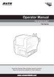
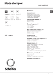
Operator Manual
For printer model:
TH2 Series
Read this Operator Manual before using this product.
Keep this document available for future reference.
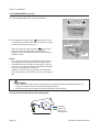
NOTE:
The printer complies with the requirements in Part 15 of FCC Rules for a Class B Computing Device.
Operating the printer in a residential area may cause unacceptable interference to radio and TV reception. If
the interference is unacceptable, you can reposition the equipment, which may improve reception.
Be sure to ask your SATO representatives about our
maintenance contracts to ensure peace of mind during your
usage of SATO products.
Please refer to the back cover for SATO Group Member Company
closest to your location. You may also visit our home page at
www.satoworldwide.com for further updated details.
Copyrights
The contents of this document are proprietary information of SATO Corporation and/or its subsidiaries in
Japan, the U.S and other countries. No part of this document may be reproduced, copied, translated or
incorporated in any other material in any form or by any means, whether manual, graphic, electronic,
mechanical or otherwise, without the prior written consent of SATO Corporation.
Limitation of Liability
SATO Corporation and/or its subsidiaries in Japan, the U.S and other countries make no representations or
warranties of any kind regarding this material, including, but not limited to, implied warranties of
merchantability and fitness for a particular purpose. SATO Corporation shall not be held responsible for errors
contained herein or any omissions from this material or for any damages, whether direct, indirect, incidental or
consequential, in connection with the furnishing, distribution, performance or use of this material.
SATO Corporation reserves the right to make changes and/or improvements in this product and document
without notice at any time.
Trademarks
SATO is a registered trademark of SATO Corporation and/or its subsidiaries in Japan, the U.S and other
countries.
Version: GBS-TH2-01rA-12-04-10OM
© Copyright 2010 SATO Corporation.
All rights reserved.
Safety Precautions
Safety Precautions
Please read the following information carefully before installing and using the printer.
Pictographic Symbols
This instruction manual and the printer labels use a variety of pictographic symbols to facilitate safe and
correct use of the printer and to prevent injury to others and property damage. The symbols and meanings for
them are given below. Be sure to understand these symbols well before reading the main text.
Example Pictographs
Warning
Caution
Ignoring the instructions marked
by this symbol and erroneously
operating the printer could result
in death or serious injury.
Ignoring the instructions marked
by this symbol and erroneously
operating the printer could result
in injury or property damage.
The
pictograph means “Caution is required.” A specific
warning symbol is contained inside this pictograph (The symbol at left is for electric shock).
The
pictograph means “Should not be done.” What is specifically prohibited is contained in or near the pictograph (The
symbol at left means “Disassembly prohibited”).
The
pictograph means “Must be done.” What is specifically
to be done is contained in the pictograph (The symbol at left
means “Unplug the power cord from the outlet”).
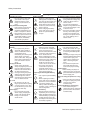
Warning
Do not set on an unstable area
• Do not set on an unstable
area, such as a wobbly table
or slanted area or an area
subject to strong vibration. If
the printer falls off or topples
over, it could injure someone.
Do not place containers full of water
or other liquid on the printer
• Do not place flower vases,
cups, or other containers
holding liquids, such as water
or chemicals, or small metal
objects near the printer. If they
are spilled and get inside the
printer, immediately turn off
the power switch, unplug the
power cord from the outlet,
and contact your SATO
reseller or technical support
center. Using the printer in this
condition could cause a fire or
electric shock.
Do not put objects inside the printer
• Do not insert or drop in metal
or burnable objects inside the
printer’s openings (cable
outlets, etc.). If foreign objects
do get inside the printer,
immediately turn off the power
switch, unplug the power cord
from the outlet, and contact
your SATO reseller or
technical support center.
Using the printer in this
condition could cause a fire or
electric shock.
TH2 Series Operator Manual
Do not use other than the specified
voltage
• Do not use other than the
specified voltage. Doing so could
result in fire or electric shock.
Always ground the connections
• Always connect the printer’s
ground wire to a ground. Not
grounding the ground wire
could result in electric shock.
When the printer has been dropped or
broken
• If the printer is dropped or
broken, immediately turn off
the power switch, unplug the
power cord from the outlet,
and contact your SATO
reseller or technical support
center. Using the printer in this
condition could cause a fire or
electric shock.
Handling of the power cord
• Do not damage, break, or
modify the power cord. Also,
do not place heavy objects on
the power cord, heat it, or pull
it because doing so could
damage the power cord and
cause a fire or electric shock.
• If the power cord becomes
damaged (core is exposed,
wires broken, etc.), contact
your SATO reseller or
technical support center.
Using the power cord in this
condition could cause a fire or
electric shock.
• Do not modify, excessively
bend, twist, or pull the power
cord. Using the power cord in
such a condition could cause a
fire or electric shock.
Do not use the printer when something is abnormal about it
• Continuing to use the printer in
the event something is
abnormal about it, such as
smoke or unusual smells
coming from it, could result in
fire or electric shock.
Immediately turn off the power
switch, unplug the power cord
from the outlet, and contact
your SATO reseller or
technical support center for
repairs. It is dangerous for the
customer to try to repair it, so
absolutely do not attempt
repairs on your own.
Do not disassemble the printer
• Do not disassemble or modify
the printer. Doing so could
result in fire or electric shock.
Contact your SATO reseller or
technical support center to
conduct internal inspections,
adjustments, and repairs.
Page i
Safety Precautions
Warning
Regarding the cutter
• Do not touch the cutter with
your hands or do not put
something into the cutter.
Doing so could result in an
injury.
Using the head cleaning fluid
• Use of flame or heat around
the head cleaning fluid is
prohibited. Absolutely do not
heat it or subject it to flames.
• Keep the fluid out of reach of
children to prevent them from
accidentally drinking it. If the
fluid is drunk, immediately
consult with a physician.
AC Adapter/ Battery Charger (Option)
Battery Pack
• Use only the specified voltage.
• Never try to take apart the
Using a different voltage may
battery pack or modify it in any
create the danger of fire or
way such as with a solder iron.
electric shock.
• Never expose the battery to
• Use only the specified AC
direct flame, throw it into fire,
adapter. Using a different one
or take any actions that may
may create the danger of fire
lead to shorting.
or electric shock.
• When charging the battery
• Never use the battery charger
pack, make sure to use the
with any other battery pack
printer or specified battery
except for the specified one.
charger.
Doing so can rupture the battery, cause leakage, fire or
electric shock.
Do not place in areas with high
humidity
• Do not place the printer in
areas with high humidity or
where condensation forms. If
condensation forms,
immediately turn off the power
switch and do not use the
printer until it dries. Using the
printer while condensation is
on it could result in electric
shock.
Carrying the Printer
• When moving the printer,
always unplug the power cord
from the outlet and check to
make sure all external wires
are disconnected before
moving it. Moving the printer
with the wires still connected
could damage the cords or
connecting wires and result in
a fire or electrical shock.
Top cover
• Be careful not to get your
fingers pinched when opening
or closing the top cover. Also
be careful the top cover does
not slip off and drop.
Power supply
• Do not operate the power
switch or plug in/unplug the
power cord with wet hands.
Doing so could result in
electric shock.
Power cord
• Keep the power cord away
from hot devices. Getting the
power cord close to hot
devices could cause the cord’s
covering to melt and cause a
fire or electrical shock.
• When unplugging the power
cord from the outlet, be sure to
hold it by the plug. Pulling it by
the cord could expose or
break the core wires and
cause a fire or electric shock.
• The power cord set that
comes with the printer is
especially made for this
printer. Do not use it with any
other electrical devices.
Replacing the Rechargable Battery
Pack
• Use only the specified battery
pack.
• When replacing the battery
pack, make sure to install the
pack in the correct orientation.
Incorrectly replacing the
battery creates the danger of
explosion, injury or damage to
surrounding areas.
Lithium coin battery
• Risk of explosion if battery is
replaced by an incorrect type.
• Apply insulation treatment for
the used battery by sealing the
contact with tape or the like
and dispose it according to the
local safety regulatory.
Caution
Page ii
Print head
• The print head is hot after
printing. Be careful not to get
burned when replacing paper
or cleaning immediately after
printing.
• Touching the edge of the print
head immediately after printing
could result in injury. Use
caution when replacing the
label or cleaning the print
head.
• You should not replace the
print head without having
received the proper training.
Loading paper
• When loading roll paper, be
careful not to get your fingers
pinched between the paper roll
and the supply unit.
When not using the printer for a long
time
• When not using the printer for
a long time, unplug the power
cord from the outlet to
maintain safety.
During maintenance and cleaning
• When maintaining and
cleaning the printer, unplug the
power cord from the outlet to
maintain safety
TH2 Series Operator Manual
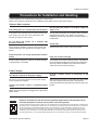
Safety Precautions
Precautions for Installation and Handling
Printer operation can be affected by the printer environment.
Refer to the following instructions for installation and handling of the TH2 Series printer.
Select a Safe Location
Place the printer on a surface that is flat and level.
If the surface is not flat and level, this may result in poor
print quality. This may also cause malfunction and
shorten the life span of the printer.
Do not place the printer on a location that
produces vibration.
Giving serious vibration or shock to the printer may
cause malfunction and shorten the life span of the
printer.
Keep the printer out of high temperature and humidity.
Avoid locations subject to extreme or rapid changes
in temperature or humidity.
Do not place the printer in a location subject to
water or oil.
Do not place the printer in a location where it will be
splashed with water or oil. Water or oil entering
inside the printer may cause a fire, electric shock, or
malfunction.
Avoid dust.
Dust build up may result in poor print quality.
Keep out of direct sunlight.
This printer has a built-in optical sensor. Exposure to
direct sunlight will make the sensor less responsive
and may cause the label to be sensed incorrectly.
Close the top cover when printing.
Power Supply
This printer requires an AC power supply.
Be sure to connect the printer to an AC power supply
via the supplied AC adapter.
Connect the power cord to a grounded power
outlet.
Provide a stable source of electricity to the
printer.
When using the printer, do not share its power outlet
with other electrical devices that could result in
power fluctuations and performance issues with your
printer.
Make sure that the printer is plugged into a grounded
power outlet.
WARNING
Disposal of Old Electrical & Electronic Equipment (Applicable In the European Union
and other European countries with separate collection systems)
A product marked with this symbol on itself or on its packaging shall not be treated as household waste. Instead it shall
be handed over to an appropriate collection point for the recycling of electrical and electronic equipment in accordance
with local regulations. Inappropriate waste handling of this product may cause detrimental consequences for the
environment and damage to human health. The recycling of materials will help to conserve natural resources and
contribute to your community. For more detailed information on recycling of this product, please contact your local
municipal organization, your household waste disposal service or the dealer from whom you purchased the product.
TH2 Series Operator Manual
Page iii
Table of Contents
TABLE OF CONTENTS
Introduction................................................................................................................1 - 1
1.1 Features of the Printer ................................................................................................. 1 - 2
1.2 Unpacking .................................................................................................................... 1 - 2
1.2.1 Included Accessories ........................................................................................................... 1 - 2
1.3 Parts Identification ....................................................................................................... 1 - 3
Installation..................................................................................................................2 - 1
2.1 Site Location ................................................................................................................ 2 - 2
2.2 Media Selection ........................................................................................................... 2 - 2
2.3 Loading Media ............................................................................................................. 2 - 3
2.3.1 Loading Roll media ............................................................................................................. 2 - 3
2.3.2 To route the label when using the dispenser ....................................................................... 2 - 5
2.4 Connections ................................................................................................................. 2 - 7
2.4.1 Standard interface connection ............................................................................................. 2 - 7
2.4.2 To activate the connected interface ..................................................................................... 2 - 7
2.4.3 Connecting the Power Cable ............................................................................................... 2 - 8
2.4.4 Turning On the Power.......................................................................................................... 2 - 9
2.4.5 Turning Off the Power ......................................................................................................... 2 - 9
2.4.6 Charging the optional battery pack with the optional battery charger ............................... 2 - 10
2.4.7 Charging the optional battery pack with the printer ........................................................... 2 - 11
2.4.8 Installing and removing the optional battery pack.............................................................. 2 - 11
2.4.9 Connecting optional scanner ............................................................................................ 2 - 12
2.4.10 Installing optional SD card .............................................................................................. 2 - 12
Operation and Configuration....................................................................................3 - 1
3.1 Operator Panel............................................................................................................. 3 - 2
3.1.1 To navigate and select item within the Menu....................................................................... 3 - 5
3.1.2 To input the field of the Menu ............................................................................................. 3 - 6
3.2 Operating Modes ......................................................................................................... 3 - 8
3.3 Print Menu.................................................................................................................. 3 - 10
3.3.1 To make print-out from a pre-defined Format .................................................................... 3 - 10
3.3.2 To make print-out from a pre-loaded Table ....................................................................... 3 - 12
3.3.3 To set the printer to On-line mode .................................................................................... 3 - 13
3.4 Main Menu ................................................................................................................. 3 - 14
3.5 Settings Menu ............................................................................................................ 3 - 14
3.6 Application Menu ....................................................................................................... 3 - 15
3.6.1 To edit the pre-loaded format............................................................................................. 3 - 16
3.6.2 To edit the FIELD menu..................................................................................................... 3 - 18
3.6.3 When Text is selected in the FIELDTYPE menu ............................................................... 3 - 20
3.6.4 When Barcode is selected in the FIELDTYPE menu......................................................... 3 - 22
3.6.5 When Line is selected in the FIELDTYPE menu ............................................................... 3 - 25
3.6.7 When Box is selected in the FIELDTYPE menu ................................................................ 3 - 26
3.6.8 When Image is selected in the FIELDTYPE menu ............................................................ 3 - 27
3.6.9 When TextBox is selected in the FIELDTYPE menu ......................................................... 3 - 29
3.6.10 About SOURCETYPE menu selection............................................................................. 3 - 31
3.6.11 To edit the pre-loaded table ............................................................................................. 3 - 36
3.6.12 To edit the F1 menu......................................................................................................... 3 - 38
3.6.13 To set the PRINT menu appearance ............................................................................... 3 - 39
Page iv
TH2 Series Operator Manual
Table of Contents
3.7 Printer Setup Menu .................................................................................................... 3 - 40
3.7.1 When Profile is selected in the SETUP menu ................................................................... 3 - 40
3.7.2 When Media is selected in the SETUP menu ................................................................... 3 - 43
3.7.3 When Print Ctrl is selected in the SETUP menu ............................................................... 3 - 47
3.7.4 When System is selected in the SETUP menu ................................................................. 3 - 54
3.7.5 When Regional is selected in the SETUP menu ............................................................... 3 - 59
3.7.6 When Network is selected in the SETUP menu (LAN) ..................................................... 3 - 62
3.7.7 When Network is selected in the SETUP menu (Wireless LAN) ...................................... 3 - 63
3.7.8 Setting of Wireless LAN Infrastructure Mode .................................................................... 3 - 65
3.7.9 Setting of Wireless LAN Ad hoc Mode .............................................................................. 3 - 68
3.8 Advanced Setup Menu............................................................................................... 3 - 70
3.9 F1 Shortcuts Menu..................................................................................................... 3 - 74
Cleaning and Maintenance .......................................................................................4 - 1
4.1 Cleaning The Print Head and Platen Roller .................................................................
4.2 How To Clean The Printer (Cleaning Kit).....................................................................
4.3 How To Clean The Printer (Cleaning Sheet) ...............................................................
4.4 Easy Replacement of Parts .........................................................................................
4-2
4-2
4-3
4-4
4.4.1 Releasing and Replacing the Print Head ............................................................................. 4 - 4
4.4.2 Releasing/ Replacing the Platen roller................................................................................. 4 - 5
4.5 Adjusting Print Quality.................................................................................................. 4 - 5
Troubleshooting ........................................................................................................5 - 1
5.1 Error signal Troubleshooting........................................................................................ 5 - 2
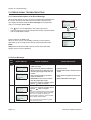
5.1.1 General description of an Error Message ............................................................................ 5 - 2
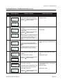
5.1.2 Error Message .................................................................................................................... 5 - 2
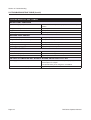
5.2 Troubleshooting Table ................................................................................................. 5 - 5
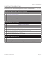
5.3 Interface Troubleshooting ............................................................................................ 5 - 7
5.4 Test Print Troubleshooting........................................................................................... 5 - 8
5.4.1 Hex Dump ............................................................................................................................ 5 - 8
5.4.2 Test label printing................................................................................................................. 5 - 8
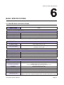
Basic Specifications..................................................................................................6 - 1
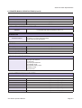
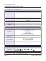
6.1 Printer Basic Specifications ......................................................................................... 6 - 1
6.2 Optional Accessories Specifications ............................................................................ 6 - 6
Interface Specifications ............................................................................................7 - 1
7.1 Interface types ............................................................................................................. 7 - 1
7.2 Universal Serial Bus (USB) Interface ........................................................................... 7 - 2
7.2.1 Basic Specifications of USB interface.................................................................................. 7 - 2
7.2.2 Pin Assignments ................................................................................................................. 7 - 2
7.3 Local Area Network (LAN) Ethernet and Wireless LAN ............................................... 7 - 3
7.3.1 Basic Specifications of LAN ................................................................................................. 7 - 3
7.3.2 Basic Specifications of Wireless LAN .................................................................................. 7 - 4
7.3.3 Software Specifications........................................................................................................ 7 - 5
7.3.4 TCP/IP Specifications .......................................................................................................... 7 - 5
7.3.5 Setting/Displayed Items ....................................................................................................... 7 - 6
7.3.6 Wireless LAN Setting .......................................................................................................... 7 - 6
TH2 Series Operator Manual
Page v
Table of Contents
Appendix ....................................................................................................................8 - 1
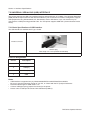
8.1 About Optional Cutter .................................................................................................. 8 - 2
8.1.1 To route the media when the cutter is installed ................................................................... 8 - 2
8.1.2 Cut position Adjustment ....................................................................................................... 8 - 2
8.1.3 Cutter replacement ............................................................................................................. 8 - 3
8.2 Positions of sensors and options ................................................................................. 8 - 3
8.3 Operation Mode Selection ........................................................................................... 8 - 4
8.3.1 Continuous Mode................................................................................................................. 8 - 4
8.3.2 Tear Off Mode...................................................................................................................... 8 - 5
8.3.3 Dispensing Mode ................................................................................................................. 8 - 6
8.3.4 Cutter Mode ......................................................................................................................... 8 - 8
8.3.5 Linerless Cutter Mode........................................................................................................ 8 - 10
8.3.6 Journal Mode ..................................................................................................................... 8 - 11
8.3.7 Tear Off Journal Mode ....................................................................................................... 8 - 12
8.4.8 Cutter Journal Mode .......................................................................................................... 8 - 13
8.3.9 Linerless Cutter Journal Mode ........................................................................................... 8 - 15
8.4 Base Reference Point ................................................................................................ 8 - 16
8.4.1 Start of print positions ........................................................................................................ 8 - 16
8.4.2 Stop positions .................................................................................................................... 8 - 16
8.5 Adjustments ............................................................................................................... 8 - 17
8.5.1 I-mark (Pitch Offset (I)) and Gap sensor (Pitch Offset (G))................................................ 8 - 17
8.5.2 Dispensing adjustment (Disp adj.) ..................................................................................... 8 - 17
8.5.3 Cutter adjustment (Cutter adj.)........................................................................................... 8 - 17
8.5.4 Position adjustment (Pos Adjust) ....................................................................................... 8 - 17
8.5.5 Pitch adjustment (Pitch) ..................................................................................................... 8 - 17
8.5.6 Offset adjustment (Offset).................................................................................................. 8 - 17
License Agreements .................................................................................................9 - 1
Sato Group of Companies ......................................................................................10 - 1
Sato Group of Companies ............................................................................................... 10 - 2
Page vi
TH2 Series Operator Manual
Section 1: Introduction
INTRODUCTION
Thank you for your investment in this SATO printer product.
This Operator Manual contains the basic information about the installation, setup, configuration, operation
and maintenance of the printer.
A total of eight topics are covered in this section, and they are organized as follows:
Section 1: Introduction
Section 2: Installation
Section 3: Configuration and Operation
Section 4: Cleaning and Maintenance
Section 5: Troubleshooting
Section 6: Basic Specifications
Section 7: Interface Specifications
Section 8: Appendix
It is recommended that you read carefully and become familiar with each section before installing and
maintaining the printer. Refer to the Table Of Contents at the front of this manual to search for the relevant
information needed. All page numbers in this manual consist of a section number followed by the page
number within the stated section.
This section assists you in unpacking the printer from the shipping container. You will also be guided through
a familiarization tour of the main parts and controls.
The following information is provided in this section:
•
•
•
Features of the printer
Unpacking
Parts Identification
TH2 Series Operator Manual
Page 1-1
Section 1: Introduction
1.1 FEATURES OF THE PRINTER
The SATO TH2 Series printer is a compact, portable Direct Thermal printer, designed with a built-in alphanumeric keypad, designed specifically for point-of-usage labelling applications. It can be used as a stand
alone printer with predefined formats, or it can be connected to a PC for variable labelling applications. The
key features of the TH2 Series are:
•
•
•
•
•
•
•
•
•
•
•
•
•
•
•
•
Application Enabled Printing (AEP)
Standard Real Time Calendar for date coded labelling
Large and adjustable LCD Screen - 128 x 64 pixels (5 lines by 16 characters)
Integrated Dispenser
Easy Media Loading
Multiple Interfaces (USB, LAN, WLAN)
Easy Maintenance
Anti-Microbial Casing
Linerless Label Support
Battery Pack and Charger Option
PS/2 Barcode Scanner Option
SD Card Option
Printer Options – Cutter, Linerless Kit, Keypad cover, Wall mount kit
Multilingual Printer [English (default), Danish, German, Spanish, French, Italian, Dutch,
Norwegian, Swedish]
European Codepages and Unicode: UTF-8 encoding support
Application Tools - AEP Works, TH PSIM, TH2 Download Tools
1.2 UNPACKING
When unpacking the printer, take note of the following:
1. The box should stay right-side up. Lift the printer out of the box carefully.
2. Remove all of the packaging from the printer.
3. Remove the accessory items from the packaging.
4. Set the printer on a solid, flat surface. Inspect the shipping container and printer for any sign of damage
that may have occurred during shipping. Please note that SATO shall hold no liability for any damage of
any kind sustained during shipping of the product.
Notes:
•
•
If the printer has been stored in the cold, allow it to reach room temperature before turning it on.
Please do not discard the original packaging box and cushioning material after installing the printer. They
may be needed in future, if the printer needs to be shipment for repairs.
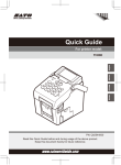
1.2.1 Included Accessories
After unpacking the printer, verify that you have the following materials:
User Documents
(Quick Guide, Warranty, etc)
AC Power plug*
AC adapter
* The shape of the power plug may vary, depending on the location where it was purchased.
Page 1-2
TH2 Series Operator Manual
Section 1: Introduction
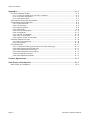
1.3 PARTS IDENTIFICATION
Front view
1
2
3
4
5
6
7
1
LCD panel
Display the operator menus, printer status,
selections for settings and error message. The
LCD panel can be tilted to an angle which is
most comfortable for the user’s view.
2
Power button
Top cover
Open this cover to load the media.
5
Operator panel
It consists of alpha-numeric keypad, arrow
buttons and other functional buttons. Please
refer to Section 3.1 Operator Panel, for
details of individual buttons.
CHARGE indicator
It turns on when the optional battery pack is
charging. It turns off when the battery pack is
fully charged or no battery pack is in the
printer.
3
4
6
Media ejection slot
Opening for media output.
7
Cover open/close latch
Press and hold for one second to turn on the
power.
Push the latch on the right side of the printer
downward to open the top cover of the printer.
Press and hold for three seconds to turn off the
power.
To close top cover, push down firmly on left
and right side of top cover until click sound is
heard. Make sure top cover is closed properly
to ensure proper feeding and printing of labels.
TH2 Series Operator Manual
Page 1-3
Section 1: Introduction
1.3 PARTS IDENTIFICATION (cont’d)
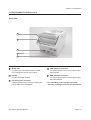
Front view with battery cover open
8
9
10
11
12
13
8
Battery pack compartment
11
To connect printer to the testing jig. This is only
for used by SATO authorised technical
personnel.
Insert the optional battery pack into the
compartment with the terminal side facing
inward.
9
VR1 (I-Mark) potentiometer
12
10
SD card slot
To insert SD card for additional memory.
Adjust for I-Mark sensor level calibration.
Refer to Section 3.7.2 When Media is
selected in the SETUP menu for details in
calibration.
CN10 terminal
13
Scanner connector
To connect printer to a PS/2 barcode scanner.
VR2 (Gap) potentiometer
Adjust for Gap sensor level calibration.
Refer to Section 3.7.2 When Media is
selected in the SETUP menu for details in
calibration.
Page 1-4
TH2 Series Operator Manual
Section 1: Introduction
1.3 PARTS IDENTIFICATION (cont’d)
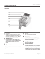
Back view
14
15
16
17
18
14
Media inlet
17
To connect printer to the host computer using
LAN interface.
An opening for Fan-folded media or media
from unwinder to feed in to the printer.
15
Handle
To carry the printer around.
16
DC input power connector
Supplies power to the printer by inserting the
power cable of the AC adapter.
TH2 Series Operator Manual
LAN interface connector*
18
USB interface connector*
To connect printer to the host computer using
the USB interface.
* The availability of the interface connector
depends on the type of printer you purchased.
Page 1-5
Section 1: Introduction
1.3 PARTS IDENTIFICATION (cont’d)
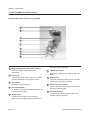
Internal view when Top cover is opened
19
20
21
22
23
24
25
26
27
19
Detects the label is taken away after
dispensed.
20
23
25
Media guide
A guide for the media to feed properly.
Platen roller
This roller feeds the media. Perform cleaning
maintenance at regular intervals.
26
Dispenser/ Tear off plate
Used to separate the label from the liner or to
tear off the journal paper.
Roll media holder
To hold the roll media and adjust it to meet the
size of the media used.
I-Mark/ Gap sensor
Detects the I-Mark on the media or gap of the
label.
Gap sensor
Detects the gap of the label.
22
24
Print head
This component is used to print on the media.
Perform maintenance at regular intervals.
21
both edges of the label roll.
Dispensing sensor (Label taken sensor)
27
Pressure bracket
To hold the dispensing roller for label liner
(backing paper) movement.
Make sure the media guides are adjusted to
Page 1-6
TH2 Series Operator Manual
Section 2: Installation
INSTALLATION
This section helps you load the consumable media in the printer, and provides adjustment instructions and
instructions to install other optional attachment units.
The following information is provided:
•
•
•
•
2.1 Site Location
2.2 Media Selection
2.3 Loading Media
2.4 Connections
TH2 Series Operator Manual
Page 2-1
Section 2: Installation
2.1 SITE LOCATION
Consider the following when setting up the printer:
• Place the printer on a solid flat surface with adequate space. Make sure there is enough space above
the printer to provide clearance for the top cover to swing open.
•
Place it away from hazardous materials or dusty environments.
•
Place it within operational distance of the host computer if connected, within interface cable
specifications.
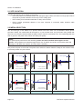
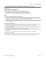
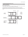
2.2 MEDIA SELECTION
The size and type of the labels to be printed should have been taken into consideration before printer
purchase. Ideally, the media width will be equal to, or just narrower than, the print head. Using media that
does not cover the print head will allow the platen roller to tread on it and wear it out. The media edge will also
wear a groove in the platen roller, which can affect print quality.
Note:
For optimal print performance and durability, please use SATO-certified label supplies on this
printer. Using supplies not tested and approved for use by SATO can result in unnecessary wear and
damage to vital parts of the printer, and may void the warranty.
This printer can print on roll media. The printer uses sensors to detect I-Marks or Gaps on the media in order
to precisely position the print content.
1.5mm (0.06”)
1.5mm (0.06”)
Ref
Ref
3mm
(0.12”)
Ref
3mm
(0.12”)
3mm
(0.12”)
* I-Mark is printed on
the back of the media.
3mm
(0.12”)
* I-Mark is printed on
the back of the media.
I-Mark Die-cut Label
Linerless label/ Journal paper
Butt-cut
Gap Label
Perforation
Ref
Ref
3mm
(0.12”)
* I-Mark is printed on
the back of the media.
I-Mark Butt-cut Label
Page 2-2
3mm
(0.12”)
3mm
(0.12”)
* I-Mark is printed on
the back of the media.
Linerless label with perforation
Media without I-Mark
TH2 Series Operator Manual
Section 2: Installation
2.3 LOADING MEDIA
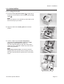
2.3.1 Loading Roll media
1. Press the cover open/close latches 1 on right side of
the printer to unlock the top cover, and then open the top
cover 2 .
Note:
2
Make sure that the cover rests firmly so that it will not fall
forward and injure your hands.
1
2. Adjust the width of the media guides to the widest
position.
1
Media
guides
3. Load the media onto the media compartment.
Then adjust the media guides inward till the media
guides press lightly against the media roll.
Turn the media roll lightly by hand and confirm that it
rotates smoothly. Otherwise, media may not be fed correctly during operation.
Note:
When using linerless label, you need to insert the
supplied label core spindle onto the roll label core and
then place the label with the spindle hook on the media
holder.
2
3
Core
spindle
Linerless label
TH2 Series Operator Manual
1
Page 2-3
Section 2: Installation
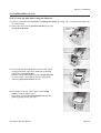
2.3 LOADING MEDIA (cont’d)
4. After pulling out the media, pass the media through the
media guides and place the leading edge of the media
on top of the platen roller.
Media guides
Note:
Make sure the printed side of the media is facing
upwards.
Printed side should face
upwards
5. Close the top cover until it snaps into position.
Notes:
•
•
Be careful not to get your fingers pinched while
closing the top cover.
To load the media in the dispenser, please refer to
Section 2.3.2 To route the label when using the
dispenser, for further instructions.
6. After loading the media, press
power button if printer
is turned off. If printer is on, press C button to clear
Cover open error.
When the printer is ready, press the
pause/ feed button
to output the leading part of the media.
power button
Caution
•
•
When replacing media, bear in mind that the print head and its surrounding area remain hot.
Keep your fingers away from these areas to prevent injury.
Avoid touching even the edge of the print head with your bare hands.
Page 2-4
TH2 Series Operator Manual
Section 2: Installation
2.3 LOADING MEDIA (cont’d)
2.3.2 To route the label when using the dispenser
1. Follow the procedures in Section 2.3.1 Loading Roll media, from step 1 to 4, to load the roll media onto
the media holder.
2. Pull the two corners of the pressure bracket out to open
the pressure bracket.
Pressure
bracket
Dispenser plate
Dispenser unit
3. Peel off the first two leading labels from the liner (backing paper) and then pull out the leading liner (backing
paper) from the media holder.
Pass the liner (backing paper) over the dispenser plate
so as to cover it. Then pass the liner (backing paper)
under the pressure bracket as shown.
Media guides
Dispenser
plate
4. If the paper is not taut, roll the paper on the media
holder so that the paper is taut.
Next, tightly close the pressure bracket with the liner
(backing paper) passing through it.
TH2 Series Operator Manual
Page 2-5
Section 2: Installation
2.3 LOADING MEDIA (cont’d)
5. Close the top cover until it snaps into position.
6. After loading the media, press
power button to turn
on the power if printer is turned off. If printer is on, press
C button to clear Cover open error.
Output label
When the printer is ready, press the
pause/ feed
button to output an empty label and stop at the
dispenser. This procedure is to ensure that the label is
loaded correctly.
Output
liner
Notes:
•
•
•
There may be cases when the dispenser does not function properly due to the thickness of the labels used.
The Dispenser unit is effective for label pitch 16 to 120
mm (0.6” to 4.7”) long. However, the label size limitation
may vary with application conditions.
Labels over 100 mm (3.9”) long may curl at dispenser
due to the nature of the material. There is no remedy for
this.
Caution
•
•
When replacing media, bear in mind that the print head and its surrounding area remain hot.
Keep your fingers away from these areas to prevent injury.
Avoid touching even the edge of the print head with your bare hands.
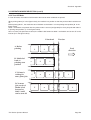
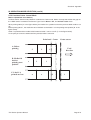
2.3.3 Overview of the Roll media loading path
Label path
Backing liner
path for use
with dispenser
Page 2-6
TH2 Series Operator Manual
Section 2: Installation
2.4 CONNECTIONS
This section explains the power cable and interface cable connection procedures.
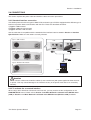
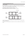
2.4.1 Standard interface connection
TH2 Series printers have three types of Main PCBs, and each type of PCB is equipped with a different type of
interface to perform data communication with the host. These are described as follows.
1) Type 1: USB on-board
2) Type 2: USB and LAN on-board
3) Type 3: Wireless LAN on-board
Use the cable that is compatible with the standard of the interface board as stated in Section 7: Interface
Specifications. Make sure the cable is correctly oriented.
Type 1: USB on-board
USB
LAN
Type 2: USB and LAN on-board
Type 3: Wireless LAN on-board
Host
Caution
Never connect or disconnect interface cables (or use a switch box) with power applied to either the host
or printer. This may caused damage to the interface circuitry in the printer/ host and is not covered by
warranty.
2.4.2 To activate the connected interface
When using LAN or WLAN as connection to the host PC, you may need to set the configuration on the
PRINTER SETUP menu. Please refer to Section 3.7.6 When Network is selected in the SETUP menu
(LAN) or Section 3.7.7 When Network is selected in the SETUP menu (Wireless LAN) for details.
TH2 Series Operator Manual
Page 2-7
Section 2: Installation
2.4 CONNECTIONS (cont’d)
2.4.3 Connecting the Power Cable
Warning
•
•
Be sure to connect the ground wire. Failure to do so may cause an electric shock.
Do not operate the power button or plug in/ unplug the power cable while your hands are wet.
Doing so may cause an electric shock.
Caution
The power cable and the AC adapter provided with this printer are for use with this printer only.
They cannot be used with other electrical devices.
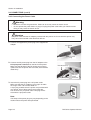
1. Connect the supplied AC power plug to the supplied AC
adapter.
AC adapter
AC power
plug
2. Connect the DC power plug from the AC adapter to the
DC input power connector on the back of the printer.
Make sure the flat side of the DC power plug is facing
upward. Secure the printer with one hand, and insert the
cable firmly.
Flat side faces up
DC power plug
DC input
power
conncetor
3. Insert the AC power plug into a AC power outlet.
Make sure that the AC voltage of your region is within
the range of AC 100 to 240V, 50/60 Hz.
A 3-pin plug is attached to the power cord provided with
your printer. One of these pins is the ground wire.
You must use a 3-pin power outlet. The plug will not
work with a 2-pin power outlet.
Note:
The shape of the power plug may vary depending on the
location where the printer was purchased.
Page 2-8
TH2 Series Operator Manual
Section 2: Installation
2.4 CONNECTIONS (cont’d)
2.4.4 Turning On the Power
Warning
Do not operate the power button or plug in/ unplug the
power cable while your hands are wet. Doing so may
cause an electric shock.
Press the
power button on the operator panel for one
second.
The LCD displays the PRINT menu after the start-up
display.
Note:
The first PRINT menu might not look like this screen. It
depends on customer application loaded into the printer.
2.4.5 Turning Off the Power
When you have completed the printing job, turn the printer
off.
Be sure to confirm that the print job is completed.
Press and hold the
power button for more than three
seconds until you hear two short beeps.
The LCD display is turned off.
Display is
turned off
Caution
•
•
•
Be sure to turn the printer power off before detaching the DC power plug of the AC adapter, or disconnecting the AC power plug.
Note that disconnecting the AC power plug in ways other than described above may prevent the
printer from correctly storing settings in memory.
No battery pack is necessary when the AC adapter is used. When the battery pack and AC
adapter are used simultaneously, the printer begins to charge the battery, if the battery is not fully
charged.
TH2 Series Operator Manual
Page 2-9
Section 2: Installation
2.4 CONNECTIONS (cont’d)
2.4.6 Charging the optional battery pack with the optional battery charger
Caution
The optional battery pack and battery charger purchased for this printer are specific to this printer only.
Do not use them for other electrical devices.
1. Connect the DC power plug of the AC adapter to the
charger unit. Then, connect the AC power cable to the
AC adapter and plug the other end of the cable to the AC
outlet.
2. Insert the battery pack into the slot, with the terminal
pointing downward.
When charging begins, the CHARGE lamp (red) lights.
When charging is complete, the CHARGE lamp lights
green (fully charged).
3. Remove the battery pack when charging is complete.
Charging time
It takes about 1.5 hours for the CHARGE lamp to turn
green when charging a completely depleted battery.
Notes:
•
•
When the CHARGE lamp is not lit, check that the battery
pack is installed securely.
The battery may not be charged when not securely
installed.
When a charged battery pack is installed, the CHARGE
lamp first lights red, then lights green.
Page 2-10
TH2 Series Operator Manual
Section 2: Installation
2.4 CONNECTIONS (cont’d)
2.4.7 Charging the optional battery pack with the printer
Caution
The power cable and the AC adapter provided with this printer are for use with this printer only.
They cannot be used with other electrical devices.
1. Insert the DC power cable into the DC IN input connector.
2. Connect the power cord to the AC adapter and plug it to
AC adapter
the outlet. When charging begins, the CHARGE LED
lights. When charging is complete, the CHARGE LED
turns off (fully charged).
DC input
connector
Charging time
It takes about 6 hours for the CHARGE LED to turn off
when charging a completely depleted battery.
2.4.8 Installing and removing the optional battery
pack
1. Open the battery cover.
2. Insert the battery pack, then close the battery cover.
Insert the battery pack with the connector side toward
the printer.
Terminal side
Battery pack
TH2 Series Operator Manual
Page 2-11
Section 2: Installation
2.4 CONNECTIONS (cont’d)
3. To remove the battery pack, press the blue hook to
unlock it, then hold the tab and pull out the battery pack.
Caution
•
•
Be sure to turn the power off before removing or replacing the battery pack.
When the power is off, the LCD display turns off. Do not remove the battery pack until the LCD
display turns off.
If you remove the battery before the LCD turns off (or goes dark), you may prevent the printer from
correctly storing settings in memory.
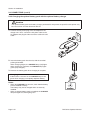
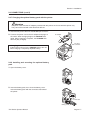
2.4.9 Connecting optional scanner
The optional scanner can be connected to the TH2 series
printer with the PS/2 connector on the right side of the printer.
1. Open the smaller cover on the right of the printer.
2. Plug in the optional scanner connector to the connector with
the arrow indication facing upwards.
Note:
Only a compatible scanner can be connected to TH2 Series
printer. Contact your SATO sales representative for more
details.
2.4.10 Installing optional SD card
The optional SD card file system is used both to extend the onboard flash memory, and to download firmware, data bases or
applications. It shall be a FAT file system, so that it can be
accessed without special applications in a PC.
You can connect the optional SD card to the CD card slot
located at the bottom right of the printer.
1. Open the bigger cover on the right of the printer.
2. Insert the SD card with the orientation the same as the
picture shown on back of the cover.
Page 2-12
TH2 Series Operator Manual
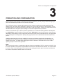
Section 3: Configuration and Operation
OPERATION AND CONFIGURATION
Before using the printer, please consult this manual first. Otherwise, you may change default settings upon
which the instructional procedures in this manual are based.
The TH2 Series printer is shipped with standard printer firmware including the standard application SA
(Stand-alone). The stand-alone application is written in the Lua scripting language. This application can be
configured by the user using the operator panel and the LCD of the printer. A users can create label formats,
add data tables and change the printer settings. This section explains these procedures.
Another more efficient way to develop custom applications is to use the Windows application development
tool, AEP Works. Instead of editing on the printer itself, AEP Works is used for this purpose. Label formats,
data tables, printer settings, fonts, images and special Lua functions are created with this tool. The application
is then packaged into an application package file (.pkg file) that can be distributed and downloaded to the
printer.
Additional download utility tools are available for end users to facilitate downloading of applications as
package files to the printer by USB or LAN/WLAN interface and to do modification of the data tables that
resides in the printer. The applications package can also be stored on a SD card which can be used to
updating the printer with a new application.
Note:
When receiving the printer, an application might have been pre-installed by SATO or a partner of SATO. Thus
the actual operation of the printer might be different from what is described in this manual. The section about
the printer setup should still apply but the actual printer setting parameters might have been set differently
from what is described as default values in this manual.
TH2 Series Operator Manual
Page 3-1
Section 3: Configuration and Operation
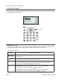
3.1 OPERATOR PANEL
The operator panel is located on the top surface of the printer. The operator panel is comprised of an alphanumeric keypad and an LCD panel.
LCD display
Icons
Arrow buttons
•
CHARGE LED indicator
The CHARGE indicator is illuminated when the installed battery pack is charging. The CHARGE indicator
turns off when the battery pack is fully charged or when no battery pack is in the printer.
•
Alpha-numeric keypad
Button
, , ,
Arrow buttons
Power
Function descriptions
These cause the cursor to shift up, down, left and right on the screen in various
setting modes.
Press and hold for one second to turn on the power.
Press and hold for three seconds to turn off the power.
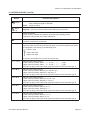
F1
Access menus with a list of pre-defined shortcuts such as [1.Print Copy], [2.Symbols], [3.Preview], [4.Time Offset], [5.Profiles], [6.Setup], [7.Info], [8.Backup].
Shortcuts can be selected under Application Settings.
F2
Scroll mode: Press once during input mode,
icon will be displayed.
Scroll within a column by pressing the , arrow buttons.
Jump mode: Press twice during input mode,
Jump between columns in a table by pressing
Page 3-2
,
icon will be displayed.
arrow buttons.
TH2 Series Operator Manual
Section 3: Configuration and Operation
3.1 OPERATOR PANEL (Cont’d)
Button
Function descriptions
Pause/
Feed
Pause: Print mode/press once; stop print job/cancel print job.
Print mode/press again: Feed label.
Feed: Feeds one label.
Menu/
Page up
Menu:
Press for more than one second to go back to main menu.
Page Up: Press once for less than one second to go up one level.
C
Delete characters.
Press one time: Deletes the character to the left of the standing cursor.
Hold down: Clear entire row of input characters.
Enter
1/a/A/-
Confirms an input sequence.
Confirms a selection in a menu list.
Press the button to toggle among the input modes. The input mode will remain
selected until the button has been pressed again. The current selected input mode
is highlighted in the display by the following icons:
= numeric input
= lower case input
= upper case input
In numeric input fields the key works as a minus sign.
1/./,/?/!
Numeric input mode: Select 1
Lower case input mode: Select , - ? ! ´ % # & ¿ : ; / \ ¯ _ " ( ) @ 1
Upper case input mode: Select , - ? ! ´ % # & ¿ : ; / \ ¯ _ " ( ) @ 1
(In Lower or Upper case input mode, press the button for two seconds to get 1)
2/A/B/C
Numeric input mode: Select 2
Lower case input mode: Select A B C Å Ä Æ À Ç 2
Upper case input mode: Select a b c å ä æ à ç 2
(In Lower or Upper case input mode, press the button for two seconds to get 2)
3/D/E/F
Numeric input mode: Select 3
Lower case input mode: Select D E F È É !"#"3
Upper case input mode: Select d e f è é $"%"3
(In Lower or Upper case input mode, press the button for two seconds to get 3)
4/G/H/I
Numeric input mode: Select 4
Lower case input mode: Select G H I Ì 4
Upper case input mode: Select g h i ì 4
(In Lower or Upper case input mode, press the button for two seconds to get 4)
5/J/K/L
Numeric input mode: Select 5
Lower case input mode: Select J K L & 5
Upper case input mode: Select j k l ' 5
(In Lower or Upper case input mode, press the button for two seconds to get 5)
TH2 Series Operator Manual
Page 3-3
Section 3: Configuration and Operation
3.1 OPERATOR PANEL (Cont’d)
Button
Function descriptions
6/M/N/O
Numeric input mode: Select 6
Lower case input mode: Select M N O Ñ Ö Ø Ò 6
Upper case input mode: Select m n o ñ ö ø ò 6
(In Lower or Upper case input mode, press the button for two seconds to get 6)
7/P/Q/R/S
Numeric input mode: Select 7
Lower case input mode: Select P Q R S (") 7
Upper case input mode: Select p q r s *"+", 7
(In Lower or Upper case input mode, press the button for two seconds to get 7)
8/T/U/V
Numeric input mode: Select 8
Lower case input mode: Select T U V Ü Ù 8
Upper case input mode: Select t u v ü ù 8
(In Lower or Upper case input mode, press the button for two seconds to get 8)
9/W/X/Y/Z
Numeric input mode: Select 9
Lower case input mode: Select W X Y Z 9
Upper case input mode: Select w x y z 9
(In Lower or Upper case input mode, press the button for two seconds to get 9)
0/+
Numeric input mode: Select 0
Lower case input mode: Select + - * / = ( ) ; < > [ ] { } ^ ¡ |"-"."/"0"0
Upper case input mode: Select + - * / = ( ) ; < > [ ] { } ^ ¡ |"1"2"3"4"0
(In Lower or Upper case input mode, press the button for two seconds to get 0)
./!
Numeric input mode: Select .
Lower case input mode: Select ! € £ $ ¥ ,
.;§
Upper case input mode: Select ! € £ $ ¥ , . ; §
@
@
(In Lower or Upper case input mode, press the button for two seconds to get .)
•
LCD Display
The display is 128 x 64 pixels with characters in five rows sixteen columns. The two right most columns in
each row are reserved for status icons.
List of Icons
No
Icon
Description
1
Displayed when printer is in numeric input mode.
2
Displayed when printer is in lower case input mode.
3
Displayed when printer is in upper case input mode.
4
Displayed when printer error occurred. Additional error message will be displayed.
5
Displayed when printer is powered up by AC power via the supplied AC adapter.
The power cord is connected; the printer is powered from a 110 - 240 V AC outlet and
the battery is being charged.
Page 3-4
TH2 Series Operator Manual
Section 3: Configuration and Operation
3.1 OPERATOR PANEL (Cont’d)
List of Icons (Cont’d)
No
Icon
Description
6
Displayed only when printer is powered by the battery.
• 0 cell: Battery empty
• 1 cell: Battery low
• 2 cells: Battery half
• 3 cells: Battery full
7
These icons are displayed only on the wireless LAN printer.
• Displayed during startup. Indicates that LAN card is not responding.
• Displayed when the LAN card is searching for signal.
• Wireless field strength -- Weak
• Wireless field strength -- Good
• Wireless field strength -- Excellent
8
Displayed when the F2 button has been pressed once during input mode. It is then
possible to scroll within a column by using the , arrow buttons.
9
Displayed when the F2 button has been pressed twice during input mode. It is then
possible to scroll between columns by using the , arrow buttons.
10
Wrench icon displayed during EDIT mode or Printer Set up.
11
Peel Sensor: This animation indicates “Peeled label not removed”.
12
Busy.
Rotating hourglass indicates that printer is busy. Such as, saving a format.
3.1.1 To navigate and select item within the Menu
When the menu displayed a list of selection, you may use arrow buttons or the
numeric buttons to make selections.
• When using arrow buttons
Press the ,
arrow buttons to scroll to the desired item. The solid bar with
reverse text indicates the selected item. Press
enter or
arrow button to
confirm the selection and the selected sub-menu will displayed.
The display can only display four items at a time. Continually press the ,
arrow buttons to display other items if any.
• When using numeric buttons
Press the associated numeric buttons to select the desired item. The selected
sub-menu will be displayed directly.
Notes:
Press
page up or
arrow button to return to the previous menu.
TH2 Series Operator Manual
Page 3-5
Section 3: Configuration and Operation
3.1 OPERATOR PANEL (Cont’d)
•
Sub menu with radio button icons
At the lowest level of the SETUP menu tree, the ,
radio button icons are
displayed on the left of the selection.
The
“pressed” radio button icon represents the current selection of the
printer. Press the ,
arrow buttons or numeric button to select the desired
new item, and then press the
enter button to confirm the new selection.
The
“pressed” radio button icon is then displayed next to the new selection.
•
Sub menu with arrow icons
When the , arrow icons are displayed beside the selection, the choice has
one or more sub-menus below. The filled arrow
icon represents the current
selection of the printer. The rules for selecting the item are similar to those of
the radio button icon.
3.1.2 To input the field of the Menu
When the menu requires inputs, the square brackets [ ] will be displayed on the
screen.
• Search Field
During the process of printing or editing the Format or Table, the search field
may display on the upper row of the screen. Alphabet search is case-insensitive.
Input of field
For example, to search for Red Onion.
1. Press the 1/a/A button to select alphabet input mode. The upper case, lower
case or numeric alphabet can be toggle cyclically.
2. Press the 7 PQRS button three times to select R.
The available characters for the pressed button is displayed on bottom line
for just one second in order for entering the next character. Before the row
of available characters disappears, keep pressing the button until the
desired character is displayed.
The printer will do a search according to the input character.
3. Press the arrow button to choose Red Onion or narrow down the search
with more characters entered.
4. Press the
Page 3-6
enter button to confirm the selection.
TH2 Series Operator Manual
Section 3: Configuration and Operation
3.1 OPERATOR PANEL (Cont’d)
Multiple word Search
If you enter [R F] in the input field, a search for words starting with R and F will
be done and the searched result is displayed.
For example, a search in the table used in the pre-defined demo will only find
the rows Reduced Fat Mayo and Reduced Fat Mayo Tub.
Category Search
If you enter an ingredient name or category name, items containing the ingredient or belonging to that category will be listed, even if the input text does not
appear at the beginning of an item name.
For example, enter SAUCE to the search field. Then press the
arrow button
to choose the desired item.
Viewing items with more characters
Some item names can be longer than the available display row.
An item with name longer than 14 characters is displayed using 2 rows. If 2
rows isn't enough the truncate symbol “>” is used.
Press F2 button once and use the ,
arrow buttons to scroll within the
column, to view full name. The
icon will be displayed in the top right corner.
Press the
or
arrow button once to scroll one character at a time.
Press and hold the
or
arrow button to jump to the beginning or end of ID
name in one step.
Press any button other than
and disable scroll function.
,
arrow buttons to make
icon disappear
Viewing and searching the item within the Table
The total information for an item is divided in different columns.
To be able to jump to another column in the table:
Press F2 button twice to activate “jump” function. The
icon will be displayed.
Use the
or
arrow button to jump between the columns.
Note:
It is possible to do a numeric or alphabetic search in each column.
Jumping between columns and performing alpha-numeric searches in one column results in a changed
item order in another column.
•
Input Field
During the process of creating the Format or Table, or setting the parameter of
the label, the input field is displayed with the square brackets [ ] on the screen.
The instructions for keying in the alphabetic or numeric characters to the input
field is the same as those for the search function.
TH2 Series Operator Manual
Page 3-7
Section 3: Configuration and Operation
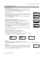
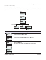
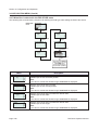
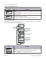
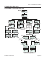
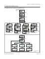
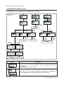
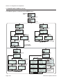
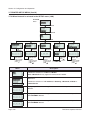
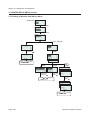
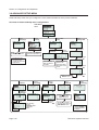
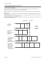
3.2 OPERATING MODES
The operating status of this printer can be set to one of the following modes:
1. PRINT menu
I---->1.Format
I------> • FMT[ ]
I---->2.Table
I------> • ID[ ]
I---->3.On-line
2. MAIN menu
I---->1.Print
I---->2.Settings
3. SETTINGS menu
I---->1.Application
I------> • 1.Edit
--> • 1.Format
--> • 2.Table
--> • 3.F1
I------> • 2.Mode
I---->2.Printer
I------> • 1.Profile
--> • 1.Select
--> • 2.Create
--> • 3.Delete
--> • 4.Print
I------> • 2.Media
--> • 1.Size
--> • 2.Sensor Type
--> • 3.Calibrate
--> • 4.Max feed
I------> • 3.Print Ctrl
--> • 1.Speed
--> • 2.Darkness
--> • 3.Media Handl.
--> • 4.Backfeed Mod
--> • 5.Adjustment
--> • 6.Image
--> • 7.Head check
--> • 8.Auto Feed
I------> • 4.System
--> • 1.Display
--> • 2.Sound
--> • 3.Auto Off
--> • 4.Test
I------> • 5.Regional
--> • 1.Lamguage
--> • 2.Time
--> • 3.Date
--> • 4.Unit
I------> • 6.Network
--> • 1.LAN
--> • 2.WLAN
Page 3-8
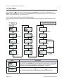
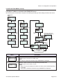
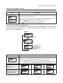
4. ADV SETUP (Advance Setup) menu:
I---->1.Start App.
I------> • 1.Standard
I---->2.Setup
I------> • 1.Profile
I------> • 2.Media
I------> • 3.Print Ctrl
I------> • 4.System
I------> • 5.Regional
I------> • 6.Network
I---->3.Hex Dump
I------> • 1.Printout
I------> • 2.To File
I---->4.Change PW
I------> • 1.admin
I------> • 2.manager
I---->5.Reset
I------> • 1.Setup
I------> • 2.SD Card
I---->6.Console
I---->7.USB
I------> • 1.Number
I---->8.Disp adj./ Cutter adj.
I---->9.Continue
I------> • PRINT menu
<F1 button shortcuts>
5. F1
I---->1.Print Copy
I---->2.Symbols
I---->3.Preview
I---->4.Time Offset
I---->5.Profiles
I---->6.Setup/
I---->7.Info
I---->8.Backup
TH2 Series Operator Manual
Section 3: Configuration and Operation
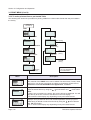
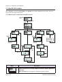
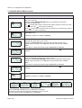
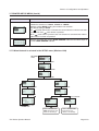
3.2 OPERATING MODES (Cont’d)
This flow chart provides a clear summary of all the modes and their access methods.
Power off
PRINT menu
Press and hold
for
one second to turn on
the power.
MAIN menu
Press and
hold
for
one second
Select 1. Print
Select 2. Settings
SETTINGS
menu
While pressing
,
press
until a long
beep is heard.
ADV SETUP
menu
TH2 Series Operator Manual
Key in the
password
Key in the
password
Page 3-9
Section 3: Configuration and Operation
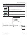
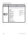
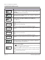
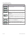
3.3 PRINT MENU
After pressing the
power button, the printer displays the PRINT menu after the start-up display. The
PRINT menu allows the user to select the pre-loaded Formats or Tables for printing, or to enter the On-line
mode to download data from connected host PC.
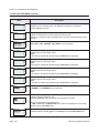
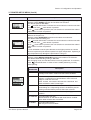
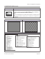
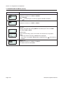
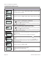
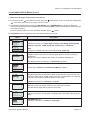
3.3.1 To make print-out from a pre-defined Format
The following flow shows the procedure for printing media from a demo format that was pre-defined in the
factory.
details of the screen may vary
* The
depending on the loaded formats.
Power on
and start-up
PRINT
menu
*
Select 1.Format
*
*
Select 1.Price Demo
Key in the old price
to the input field
Press “M” to
search “Mountain”
Press
to
pause printing
*
Key in the Mark
Down value
Press F1 for
Help menu
Press
to
continue
printing
*
*
Menu
Start printing
Press
*
Select 3.David
Press
*
*
Press
Key in the Quantity
to the input field
Press
Press
Press F1
Press
to
continue
printing
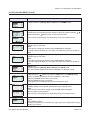
Description
PRINT menu
The contents of the PRINT menu can be edited. The three items, Format, Table
and On-line, can be set to be shown or hidden on the display. Please refer to
Section 3.6.13 To set the PRINT menu appearance, for details.
Displays search field. Enables selection of format to print by entering characters
in search field or by using the ,
arrow buttons and
enter button.
*The contents of the display vary depending on the pre-loaded formats.
Page 3-10
TH2 Series Operator Manual
Section 3: Configuration and Operation
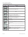
3.3 PRINT MENU (Cont’d)
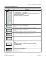
Menu
Description
Displays a list of products for the selected formats and enables alphabetic
search by input of character(s) in ID field or select from the list by using the
arrow buttons and
enter button.
*The contents of the display vary depending on the pre-loaded formats.
,
Displays list of pre-defined names.
*The contents of the display vary depending on the pre-loaded formats.
Displays WAS Price input field and enables new input.
*The contents of the display vary depending on the pre-loaded formats.
Displays mark-down input field and enables new input.
*The contents of the display vary depending on the pre-loaded formats.
Displays Quantity input field and enables new input.
Displays number of printed labels and the total number of labels to print.
If printing is paused:
Displays number of printed labels and the total number of labels to print.
Help menu if F1 is pressed.
This is the printout when selecting product
ID as Mountain, Marked by: as David,
WAS Price as 49.90 and Mark Down %
as 25.
TH2 Series Operator Manual
Page 3-11
Section 3: Configuration and Operation
3.3 PRINT MENU (Cont’d)
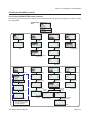
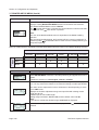
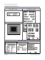
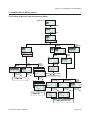
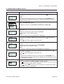
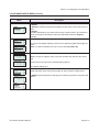
3.3.2 To make print-out from a pre-loaded Table
The following flow shows the procedure for printing media from a demo table format that was pre-loaded in
the factory.
Power on
and start-up
PRINT
menu
Select 2.Table
Press
*
Select 1.QSR Demo
Start printing
Press
to
pause printing
*
Press “B” to
search “Bacon”
Press F1 for
Help menu
Press
to
continue
printing
*
Press
Press F1
details of the screen
* The
may vary depending on
Key in the Quantity
to the input field
Menu
Press
to
continue
printing
the loaded tables.
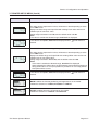
Description
PRINT menu
The contents of the PRINT menu can be edited. The three items, Format, Table
and On-line, can be set to be shown or hidden on the display. Please refer to
Section 3.6.13 To set the PRINT menu appearance, for details.
Displays search field and enables selection of format to print by entering characters in search field or by using the ,
arrow buttons and
enter button.
Note:
If there is only one table in the printer, this screen will not be displayed. You will
step directly to the sub content of the table as in the next display.
*The contents of the display vary depending on the pre-loaded formats.
Displays list of pre-defined items and enables alphabetic search by input of
character(s) in ID field or select from the list by using the ,
arrow buttons
and
enter button.
*The contents of the display vary depending on the pre-loaded formats.
Page 3-12
TH2 Series Operator Manual
Section 3: Configuration and Operation
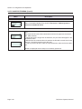
3.3 PRINT MENU (Cont’d)
Menu
Description
Displays Quantity input field and enables new input.
Displays number of printed labels and total number of labels to print.
If printing is paused:
Displays number of printed labels and total number of labels to print.
Help menu if F1 is pressed.
This is the print-out of the above example.
3.3.3 To set the printer to On-line mode
From the PRINT menu, the user can set the printer to On-line mode.
In On-line mode, formats can be printed directly from the connected host PC.
Press 3 button or use the ,
arrow buttons and
enter button to select Online.
TH2 Series Operator Manual
Page 3-13
Section 3: Configuration and Operation
3.4 MAIN MENU
After pressing the
power button, the printer enters the PRINT menu or Format
search, Table search or On-line menu, depending on the settings of the MODE
menu. Then press and hold
button for more than one second to enter the
MAIN menu.
From the MAIN menu, you may go to PRINT menu or SETTINGS menu.
3.5 SETTINGS MENU
TH2 Series printer has two selections of settings. Application setting allows user to add new, edit or delete
the loaded formats while Printer setting allows the user to configure the printer. Please note that all the
changes done in Application Setting menu are temporary saved in the printer. You cannot upload them back
to the host PC.
1. When the MAIN MENU is displayed, press the “2” button or press
ton and then
arrow but-
button to select Settings menu.
2. A password is required before entering SETTINGS menu. PASSWORD input
screen is displayed.
The default passwords are 6677 (MANAGER) and 96726 (ADMIN). These two
passwords can be changed in the Advance Setup mode.
Key in the password with the numeric buttons and then press
button.
3. The SETTINGS menu is displayed.
You can select Application settings or Printer settings.
Page 3-14
TH2 Series Operator Manual
Section 3: Configuration and Operation
3.6 APPLICATION MENU
In the APPLICATION menu of the SETTINGS mode, the user can edit the pre-loaded formats or tables, or set
the functions of the F1 button in Edit selection. User can also set the appearance of the PRINT menu in Mode
selection.
SETTINGS
menu
Select 1.Application
Select 1.Edit
Select 1.Format
Menu
Select 2.Table
Select 3.F1
Description
APPLICATION menu.
Enables the selection of Edit or Mode.
Enables selection of Format, Table or F1 from EDIT menu.
FORMAT, TABLE or F1 menu will be displayed, depending on the selection
done on the EDIT menu.
The details of each selection are explained in the following pages.
TH2 Series Operator Manual
Page 3-15
Section 3: Configuration and Operation
3.6 APPLICATION MENU (Cont’d)
3.6.1 To edit the pre-loaded format
Formats pre-loaded in the printer can be modified, or a new format can be created and stored in the printer.
Unwanted formats can be also deleted from the printer to increase memory space. The following flow
summarizes the sequence for editing the format.
Application
EDIT menu
details of the screen
* The
may vary depending on
the loaded formats.
Select 1.Format
Select 1.Cancel
will not save your
format and return
to the initial
screen.
Select 2.Yes will
save your format
and return to the
initial screen.
Select 1.Modify
Select 2.New
*
Select Format
to be modified
*
Key in the new
Format name
Select “Test Meal”
as an example
*
Set the LENGTH
of the format
*
Select Format
to be deleted
*
*
Press
Select 3.Delete
*
Select “Test Meal”
as an example
Press
*
Set the LENGTH
of the format
*
Select
1.Cancel
Select 2.Yes
Proceed
deleting format
Set the WIDTH
of the format
Set the WIDTH
of the format
Select desired
function, Modify,
New or Delete.
Select 2.New only.
When no formats loaded, selecting
Modify or Delete will displayed
“Not existing!”.
Return to
Format search
screen
Press
Proceed to the FIELD menu
flow procedure
Page 3-16
TH2 Series Operator Manual
Section 3: Configuration and Operation
3.6 APPLICATION MENU (Cont’d)
Menu
Description
Enables selection of Modify, New or Delete from FORMAT menu.
Displays a search field and a list of formats to modify or delete.
Enables search for existing format to modify or delete by scrolling with the
arrow buttons and
enter button or input in search field.
,
*The contents of the display vary depending on the pre-loaded formats.
Displays input range, existing format LENGTH and unit.
Enables input of new value.
Note:
If the value is outside the allowed range, Invalid will be displayed.
If the input field is left blank or if 0 is input, the value from printer set up will be
used.
Displays input range, existing format WIDTH and unit.
Enables input of new value.
Note:
If the value is outside the allowed range, Invalid will be displayed.
If the input field is left blank or if 0 is input, the value from printer set up will be
used.
FIELD menu.
Enables selection of Modify, New or Delete from FIELD menu.
The next following pages show further explanation on editing the Field.
If Menu/Page up
button is pressed on FIELD menu of LENGTH setting
screen, the printer prompts to save the modified or new format.
Selecting 1.Cancel will not save your format.
Selecting 2.Yes will save your format.
A time-glass icon is rotating while printer is saving your work.
Displays input field for new format.
Enables creation of new format, starting with input of format name.
Note:
If the chosen format name already exists, Invalid will be displayed.
The input field is case sensitive.
*The contents of the display vary depending on the pre-loaded formats.
If 1.Cancel is selected, the format will not be deleted. The format list will be displayed.
Select 2.Yes to delete.
A rotating hourglass icon is visible in the upper right corner while printer is busy
deleting your format.
TH2 Series Operator Manual
Page 3-17
Section 3: Configuration and Operation
3.6 APPLICATION MENU (Cont’d)
3.6.2 To edit the FIELD menu
The following flow summarizes the sequence for editing the field while creating a new format or modify an
existing format.
FIELD menu
Select 2.New
Select 1.Modify
Select 3.Delete
*
*
Press
Key in the new
Field name
*
Press
Select Field to
be modified
Select Field
to be deleted
Proceed
deleting format
Return to Field
search screen
Proceed to the selected
FIELDTYPE menu flow
procedure
After modifying the
selected field, printer
returns to Field search
screen.
After creating a new field,
input the name of the next
new field is prompt.
details of the screen
* The
may vary depending on
the loaded formats.
Key in the new
Field name
Menu
Description
FIELD menu.
Enables selection of Modify, New or Delete from FIELD menu.
The next following pages show further explanation on editing the Field.
Displays search field and a list of existing fields associated with the selected format.
Enables selection of field(s) to modify or delete by scrolling with the , arrow
buttons and
enter button or input the respective number directly.
*The contents of the display vary depending on the pre-loaded formats.
Page 3-18
TH2 Series Operator Manual
Section 3: Configuration and Operation
3.6 APPLICATION MENU (Cont’d)
Menu
Description
Displays an input field.
Enables the creation of new field, starting with input of field name.
A suggestion to field name is given as [F1].
For an example, change the field name to Header.
*The contents of the display vary depending on the pre-loaded formats.
Enables selection of suitable FIELDTYPE for the new field.
Text, Barcode, Line, Box, Image or Text Box can be selected.
TH2 Series Operator Manual
Page 3-19
Section 3: Configuration and Operation
3.6 APPLICATION MENU (Cont’d)
3.6.3 When Text is selected in the FIELDTYPE menu
The following flow summarizes the sequence for defining the field type while editing the field of the format.
FIELDTYPE
menu
details of the screen
* The
may vary depending on
the pre-loaded fonts.
Select 1.Text
Select 2.bitmap
Select 1.truetype
*
*
Select Font
Select Font
Set the vertical
magnification value
Set horizontal
position
Select anchor
point
Set the field
size
Set vertical
position
Set direction
Select anchor
point
Set the
horizontal
magnification
value
Set horizontal
position
Set direction
Set the vertical
position
Select the source.
Please refer to the flow
of individual selection.
Menu
Select the source.
Please refer to the flow
of individual selection.
Description
FONTTYPE menu.
Enables selection of true type font or bitmap font from FONTTYPE menu.
Page 3-20
TH2 Series Operator Manual
Section 3: Configuration and Operation
3.6 APPLICATION MENU (Cont’d)
Menu
Description
Displays a list of true type FONT available for the printer.
*Your list of fonts may be different from this example depending on the fonts
downloaded to your printer.
Select the font according to your preference.
Displays input range and input field.
Enables input of text field horizontal position.
Note:
If the value is outside the allowed range, Invalid will be displayed.
Displays input range and input field.
Enables input of text field vertical position.
Note:
If the value is outside the allowed range, Invalid will be displayed.
Displays input range and default field size.
Enables input the size of text field.
Note:
If the value is outside the allowed range, Invalid will be displayed.
Enables the selection of anchor point of the text field.
TOP_LEFT, TOP_CENTER, TOP_RIGHT can be selected.
Displays input range and input field.
Enables setting of text field direction. The direction can be set in 360 steps (0 359; describing the degrees of rotation).
Note:
If the value is outside the allowed range, Invalid will be displayed.
Enables selection of SOURCETYPE for the new field.
Fix, Table, Counter, Copy, Script, Time, Input or Select can be selected.
Displays a list of bitmap FONT available for the printer.
* Your list of fonts may be different from this example depending on the fonts
downloaded to your printer.
Select the font according to your preference.
Displays input range and input field.
Enables input of text field horizontal magnification.
Note:
If the value is outside the allowed range, Invalid will be displayed.
TH2 Series Operator Manual
Page 3-21
Section 3: Configuration and Operation
3.6 APPLICATION MENU (Cont’d)
Menu
Description
Displays input range and input field.
Enables input of text field vertical magnification.
Note:
If the value is outside the allowed range, Invalid will be displayed.
Enables setting of text field direction in 4 angles; 0, 90, 180 or 270 degree.
3.6.4 When Barcode is selected in the FIELDTYPE menu
The following flow summarizes the sequence for defining the field type while editing the field of the format.
FIELDTYPE
menu
Select
2.Barcode
Only applicable for:
GS1-128
Select barcode
direction
Only applicable for:
EAN-8, GS1-128 Composite
CC-A/B, GS1-128 Composite
CC-C, GS1-128, Interleaved 2 of
5, UPC-A, UPC-E, Bookland,
Codabar, Code 128, Code 39,
EAN-13
Set barcode
height
Set the human readable
below barcode info.
Only applicable for:
Micro QR Code, QR
Code, Data Matrix
Set the code cell size
Only applicable for:
Micro QR Code, QR Code
Select barcode
Select correction
level
Only applicable for:
Interleaved 2 of 5, Codabar,
Code 39
Set horizontal
position
Only applicable for:
Micro QR Code,
QR Code
Select
encoding
Select barcode ratio
Not available for:
Data Matrix, Micro QR Code,
QR Code.
Set the vertical
position
Set the barcode narrow width
Select the source.
Please refer to the flow
of individual selection.
Only applicable for:
EAN-8, EAN-13, UPC-A,
UPC-E, Code 39,
Codabar, Bookland,
Interleaved 2 of 5,
GS1-128, Code 128
Select anchor
point
Page 3-22
Set the human
readable barcode info.
TH2 Series Operator Manual
Section 3: Configuration and Operation
3.6 APPLICATION MENU (Cont’d)
Menu
Description
Displays search field and a list of barcodes available in the printer.
Enables selection of barcodes using input in search field or scrolling with the
arrow buttons and
enter button.
* Your list of barcodes may be different from this example depending on the
printer firmware version used.
Select the font according to your preference.
Default barcode is Code 39.
,
Displays input range and input field.
Enables input of barcode horizontal position.
Note:
If the value is outside the allowed range, Invalid will be displayed.
Displays input range and input field.
Enables input of barcode vertical position.
Note:
If the value is outside the allowed range, Invalid will be displayed.
Enables the selection of anchor point of the barcode field.
TOP_LEFT, TOP_CENTER, TOP_RIGHT can be selected.
Enables setting of barcode field direction in 4 angles; 0, 90, 180 or 270 degree.
Displays input range and input field with default height.
Enables input of new barcode height.
Note:
If the value is outside the allowed range, Invalid will be displayed.
Only applicable for:
EAN-8, GS1-128 Composite CC-A/B, GS1-128 Composite CC-C, GS1-128
Interleaved 2 of 5, UPC-A, UPC-E, Bookland, Codabar, Code 128, Code 39,
EAN-13
Enables selection of correction level.
Default selection is 2.Standard
Only applicable for:
Micro QR Code, QR Code
TH2 Series Operator Manual
Page 3-23
Section 3: Configuration and Operation
3.6 APPLICATION MENU (Cont’d)
Menu
Description
Enables selection of barcode ratio.
Only applicable for:
Interleaved 2 of 5, Codabar, Code 39
Displays input range and input field with default value.
Enables input of barcode narrow width.
Not available for:
Data Matrix, Micro QR Code, QR Code
Note:
If the value is outside the allowed range, Invalid will be displayed.
Enables the selection of human readable barcode info.
Only applicable for:
EAN-8, EAN-13, UPC-A, UPC-E, Code 39, Codabar, Bookland, Interleaved 2 of
5, GS1-128, Code 128
Enables selection of human readable below barcode info.
Only applicable for:
GS1-128
Displays input range and input field with default value.
Enables input of barcode cell size.
Note:
If the value is outside the allowed range, Invalid will be displayed.
Only applicable for:
Micro QR Code, QR Code, Data Matrix
Default cell size of Micro QR Code and QR Code is 4 and the range is 1 - 32
Default cell size of Data Matrix is 2 and the range is 1 - 16
Enables selection from encoding menu.
Default selection is 5.Auto
Only applicable for:
Micro QR Code, QR Code
Page 3-24
TH2 Series Operator Manual
Section 3: Configuration and Operation
3.6 APPLICATION MENU (Cont’d)
3.6.5 When Line is selected in the FIELDTYPE menu
The following flow summarizes the sequence for defining the field type while editing the field of the format.
FIELDTYPE
menu
Select
3.Line
Set horizontal
position
Set line
vertical delta
Set vertical
position
Set line
thickness
Set line
horizontal delta
Menu
Proceed to the FIELD
search screen or new
field NAME input
screen depending on
the previous operation.
Description
Displays input range and input field.
Enables input of line horizontal position.
Note:
If the value is outside the allowed range, Invalid will be displayed.
Displays input range and input field.
Enables input of line vertical position.
Note:
If the value is outside the allowed range, Invalid will be displayed.
Displays input range and input field with default value.
Enables input of line horizontal delta.
Note:
If the value is outside the allowed range, Invalid will be displayed.
Displays input range and input field with default value.
Enables input of line vertical delta.
Note:
If the value is outside the allowed range, Invalid will be displayed.
Displays input range and input field with default value.
Enables input of line thickness.
Note:
If the value is outside the allowed range, Invalid will be displayed.
TH2 Series Operator Manual
Page 3-25
Section 3: Configuration and Operation
3.6 APPLICATION MENU (Cont’d)
3.6.7 When Box is selected in the FIELDTYPE menu
The following flow summarizes the sequence for defining the field type while editing the field of the format.
FIELDTYPE
menu
Select
4.Box
Set horizontal
position
Set box
height
Set vertical
position
Set box frame
thickness
Set box
width
Select anchor
point
Proceed to the FIELD
search screen or new
field NAME input
screen depending on
the previous operation.
Menu
Description
Displays input range and input field.
Enables input of box horizontal position.
Note:
If the value is outside the allowed range, Invalid will be displayed.
Displays input range and input field.
Enables input of box vertical position.
Note:
If the value is outside the allowed range, Invalid will be displayed.
Displays input range and input field with default value.
Enables input of box width.
Note:
If the value is outside the allowed range, Invalid will be displayed.
Displays input range and input field with default value.
Enables input of box height.
Note:
If the value is outside the allowed range, Invalid will be displayed.
Page 3-26
TH2 Series Operator Manual
Section 3: Configuration and Operation
3.6 APPLICATION MENU (Cont’d)
Menu
Description
Displays input range and input field with default value.
Enables input of box frame thickness.
Note:
If the value is outside the allowed range, Invalid will be displayed.
Enables the selection of anchor point of the box field.
TOP_LEFT, TOP_CENTER, TOP_RIGHT can be selected.
Anchor Point is a field co-ordinate representing the field regarding positioning
and rotation.
3.6.8 When Image is selected in the FIELDTYPE menu
The following flow summarizes the sequence for defining the field type while editing the field of the format.
FIELDTYPE
menu
Select
5.Image
Set horizontal
position
Select anchor
point
Set the vertical
position
Select the source.
Please refer to the flow
of individual selection.
Set the horizontal
magnification value
If 1.FIX is
selected
Set the vertical
magnification value
Select loaded
image
Proceed to the FIELD
search screen or new
field NAME input
screen depending on
the previous operation.
TH2 Series Operator Manual
Page 3-27
Section 3: Configuration and Operation
3.6 APPLICATION MENU (Cont’d)
Menu
Description
Displays input range and input field.
Enables input of image horizontal position.
Note:
If the value is outside the allowed range, Invalid will be displayed.
Displays input range and input field.
Enables input of image vertical position.
Note:
If the value is outside the allowed range, Invalid will be displayed.
Displays input range and input field.
Enables input of image field horizontal magnification.
Note:
If the value is outside the allowed range, Invalid will be displayed.
Displays input range and input field.
Enables input of image field vertical magnification.
Note:
If the value is outside the allowed range, Invalid will be displayed.
Enables the selection of anchor point of the image field.
TOP_LEFT, TOP_CENTER, TOP_RIGHT can be selected.
Enables selection of SOURCETYPE for the new field.
Fix, Table, Counter, Copy, Script, Time, Input or Select can be selected.
Displays search field and a list of images available in the printer.
Enables selection of images using input in search field or scrolling with the ,
arrow buttons and
enter button.
Existing images are pre-loaded and can be used in formats. The ones listed are
for demo formats.
New images can be loaded from a host or AEP Works.
Page 3-28
TH2 Series Operator Manual
Section 3: Configuration and Operation
3.6 APPLICATION MENU (Cont’d)
3.6.9 When TextBox is selected in the FIELDTYPE menu
The following flow summarizes the sequence for defining the field type while editing the field of the format.
FIELDTYPE
menu
Select
6.TextBox
Set textbox
width
Select
alignment point
Set the number
of textbox rows
Set top margin
Enable input of
new delimiter
Set bottom
margin
Set right
margin
Select text
style
Select FIT
as 2.OFF
Select
2.bitmap
Enable input of
new hyphen
FIT screen is displayed
when ROWS was set as 1.
Select FIT
as 1.ON
Select
1.truetype
Set left margin
Proceed to the
FONTTYPE setting
menu.
Menu
Description
Displays text box width input range and input field with default value.
Enables input of new text box width value.
Note:
If the value is outside the allowed range, Invalid will be displayed.
Displays number of text box rows input range and input field.
Enables input of new number of rows.
Notes:
• When “0” is set, the textbox will resize to as many rows needed depending
on its data.
• If the value is outside the allowed range, Invalid will be displayed.
TH2 Series Operator Manual
Page 3-29
Section 3: Configuration and Operation
3.6 APPLICATION MENU (Cont’d)
Menu
Description
Displays delimiter input field and enables input of new delimiter.
Delimiter is a forced wrap point. The delimiter character is not printed.
Default delimiter is space.
Displays hyphen input field and enables input of new hyphen.
Hyphen is used when a word is longer than the text box.
Hyphen is a wrap point sign showing that the rest of the word is printed on the
next line.
Enables the selection of alignment point.
TOP_LEFT, TOP_CENTER, TOP_RIGHT can be selected.
Displays top margin range and input field.
Enables input of new margin value.
Note:
If the value is outside the allowed range, Invalid will be displayed.
Displays bottom margin range and input field.
Enables input of new margin value.
Note:
If the value is outside the allowed range, Invalid will be displayed.
Displays left margin range and input field.
Enables input of new margin value.
Note:
If the value is outside the allowed range, Invalid will be displayed.
Displays right margin range and input field.
Enables input of new margin value.
Note:
If the value is outside the allowed range, Invalid will be displayed.
Enables selection of text style.
1.NORMAL or 2.INVERSE can be selected.
FIT menu will only appear if ROWS is set to 1 as mentioned above.
Enables selection of FIT function.
Selecting 1.ON will scale the text to fit in the entire box width.
FIT is only applicable on true type fonts.
If 1.ON is selected, the FONTTYPE menu will not be displayed. You will step
directly to true type FONT menu.
FONTTYPE menu.
Enables selection of true type font or bitmap font from FONTTYPE menu.
Page 3-30
TH2 Series Operator Manual
Section 3: Configuration and Operation
3.6 APPLICATION MENU (Cont’d)
3.6.10 About SOURCETYPE menu selection
The following flow summarizes the sequence for selecting the source type while creating a new field or modify
an existing field.
SOURCETYPE
menu
Select
1.Fix
Select
2.Table
Select
3.Counter
Select
4.Copy
Key in fix
data
Select
table
Set the
start value
Select field
to copy from
Select the column
as source
Set the
step value
Set the
Max value
Select 5.Script
Select 6.Time
Select 7.Input
Set offset
time by days
Set the
display text
Select 8.Select
*
Key in the
prompt text
Select
Function
Set offset
time by hour
Set the decimal
in price
Set the price
Set date
format
Select
1,2 or 3
Set the max number
of input character
Select input format
Select
4 or 5
Enter a list
of choices
Set the max number
of input character
details of the screen
* The
may vary depending on
the loaded scripts.
Set the number of decimal
TH2 Series Operator Manual
Page 3-31
Section 3: Configuration and Operation
3.6 APPLICATION MENU (Cont’d)
Fix
Menu
Description
Fix: Source data for the field is fixed and defined once and is always the
same for a field.
Displays input field.
Enables input of fix data, text or number.
Table
Table: source data for the field is taken from a table that has been
imported to the printer. A table is the “database” of the printer.
Displays search field, TBL[ ] and a list of tables available in the printer.
Enables selection of tables using input in search field or scrolling with the
,
arrow buttons and
enter button.
Select one of the data tables from the list. In this case the QSR demo table
is selected.
The different columns in the table are listed. Select the column that will be
the source to the field.
Counter: the source data for the field is a counter.
Counter
Displays input field.
Enables input of counter START value.
Displays input field.
Enables input of counter STEP value.
Displays input field.
Enables input of counter MAX value.
Script
Copy
Copy: source data for the field is copied from another field.
Page 3-32
Displays input field.
Enables selection of field to copy from the selected format.
*The contents of the display vary depending on the pre-loaded formats.
Script: source data for a field is the output from a script. A script is a small
Lua program.
This list contains functions that can be called from the script. Functions
often have arguments for input values.
These arguments can either be fix values like 12.34 or a variable that
holds the price like the piped value variable Value.
TH2 Series Operator Manual
Section 3: Configuration and Operation
3.6 APPLICATION MENU (Cont’d)
Script -- LowPrice
Menu
Description
A list of available functions is displayed. The names of these functions can
vary between applications and may not correspond to this screen shot.
LowPrice is a function that is used when decimals in a price must be set
to a fix value.
Argument #1, dd.
Input number(s) to replace existing decimals in price; 1 or 2 digits.
Argument #2, price.
Input price or reference to price.
Script -- WeekDay
WeekDay is a function that is used for fields that should only be visible for
certain weekdays.
Argument #1, daynumber.
Input 1-7.
Argument #2, value.
Input actual daynumber or reference to it.
Argument #3, data.
Input the formatted value Data.
Script -- Truc
Trunc is a function that truncates a number to n decimals.
Argument #1, n.
Input number of decimals.
Argument #2, number.
Input price or reference to price.
TH2 Series Operator Manual
Page 3-33
Section 3: Configuration and Operation
3.6 APPLICATION MENU (Cont’d)
Menu
Description
Script -- MarkDown
MarkDown is a function that calculates a price reduced by percentage.
Argument #1, percentage.
Input 0-99.
Argument #2, price.
Input price or reference to price.
Script -- Round
Round is a function that round a number to n decimals.
Argument #1, n.
Input number of decimals.
Argument #2, number.
Input number (price) or reference to price.
AddTime is a function that adds time.
Script -- AddTime
Argument #1, d.
Input days.
Argument #2, h.
Input hours.
Argument #3, m.
Input minutes.
Argument #4, value is time in seconds.
This value is normally calculated when sourcetype time is used. The reference to it is the variable Value
Page 3-34
TH2 Series Operator Manual
Section 3: Configuration and Operation
3.6 APPLICATION MENU (Cont’d)
Menu
Description
Time: source data for the field is coming from the real-time clock of the
printer.
Time
Select which offset in number of days that shall be added to the current
time. Can be a positive or negative offset. Zero offset will not add any days
to the clock.
Select which offset in number of hours that shall be added to the current
time. Can be a positive or negative offset. Zero offset will not add any
hours to the clock.
Type in date format attribute.
The date can be printed according to a specific format. In this case, %c is
in seconds.
For example, %D will print the date as month/day/year.
The different format attributes are describes under “formatter” in XML
specification STB00102. Please contact SATO representative for more
details.
Input: source data for the field is coming from input data from the keyboard of the printer, an external PS/2 keyboard or a scanner.
Input display text that shall be prompted in the display before an input
value.
Range: 0 - 14
0 = unlimited number of characters.
Input
Enables to select from INPUT FORMAT menu.
1.String: Input format shall be a string value. A string is an alphanumeric
value.
2.Unsigned integer: Input format shall be an unsigned numeric integer
value.
3.Signed integer: Input format shall be a signed integer numeric value.
4.Unsigned Float: Input format shall be an unsigned float numeric value.
5.Signed Float: Input format shall be a signed float numeric value.
Input the maximum number of characters allowed for the input field.
Input 0 is unlimited length.
Input the number of decimals for the numeric input value allowed for the
input field.
Input 0 is 2 decimals (default).
TH2 Series Operator Manual
Page 3-35
Section 3: Configuration and Operation
3.6 APPLICATION MENU (Cont’d)
Menu
Description
Select: data for the field is coming from a list of choices in a menu.
Select
Write the prompt text for the input field.
Write in a list of choices. Separate with comma sign.
For example, E. Jane, Kevin, etc.
3.6.11 To edit the pre-loaded table
Tables pre-loaded in the printer can be modified, or unwanted tables can be also deleted from the printer to
increase more memory space. The following flow summarizes the sequence for editing the tables.
Application
EDIT menu
details of the screen
* The
may vary depending on
the loaded tables.
Select 2.Table
Select 2.Delete
Select 1.Modify
*
*
Select Table
to be deleted
Select Table to
be modified
Select
1.Cancel
Select 2.Yes
Select 1.Modify
*
Select row to
be edit
*
Edit the
row field
Select 2.New
*
New input for
1st column
*
New input for
2nd column
*
New input for
3rd column
and so on..
Page 3-36
Select 3.Delete
*
Select row to
be deleted
*
Selected row
was deleted
Select 4.Copy
*
Select row
to be copied
Proceed
deleting table
Return to
Table search
screen
*
Set new row
to copy to
*
Selected row
was copied
TH2 Series Operator Manual
Section 3: Configuration and Operation
3.6 APPLICATION MENU (Cont’d)
Menu
Description
Enables selection of Modify or Delete from TABLE menu.
Displays a search field and a list of tables to modify or delete.
Enables search for existing table to modify or delete by scrolling with the
arrow buttons and
enter button or input in search field.
*The contents of the display vary depending on the pre-loaded tables.
,
Enables selection of Modify, New, Delete or Copy from ROW menu.
Displays a search field and a list of rows to modify, delete or copy.
Enables search for existing row to modify, delete or copy by scrolling with the
,
arrow buttons and
enter button or input in search field.
*The contents of the display vary depending on the pre-loaded tables.
Enables modification of selected row name.
*The contents of the display vary depending on the pre-loaded tables.
After selection of creating a New ROW, the printer will request data input for the
new row.
*The contents of the display vary depending on the pre-loaded tables.
Specific first column of the table chosen for edit.
In this example, the printer enables input of Preset No. for new row.
Specific second column of the table chosen for edit.
In this example, the printer enables input of Product name for new table row.
Specific third column of the table chosen for edit.
In this example, the printer enables input of Label. It is the format name to use
for the data in this row.
After selection the field to be copied, the printer will request to enter a new
entries for the copied data to be save as.
In this example, the printer enables input of Preset No. for the new copied row.
*The contents of the display vary depending on the pre-loaded tables.
In this example, Bacon is now copied.
*The contents of the display vary depending on the pre-loaded tables.
TH2 Series Operator Manual
Page 3-37
Section 3: Configuration and Operation
3.6 APPLICATION MENU (Cont’d)
Menu
Description
If 1.Cancel is selected, the table will not be deleted. The table list will be displayed.
Select 2.Yes to delete.
A rotating time-glass icon is visible in the upper right corner while printer is busy
deleting your table.
If 2.Yes is selected and confirmed, the selected table 10.Shoe table (in this
example) will be deleted from table list.
*The contents of the display vary depending on the pre-loaded tables.
3.6.12 To edit the F1 menu
The selection of pre-defined functions that appear in F1 menu can be set to displayed or not to. The following
flow summarizes the sequence of setting the F1 menu.
Application EDIT menu
Press
to
return to
EDIT menu
Select 3.F1
Press the associated
numeric button to toggle
your selection(s), or
select by using /
arrow buttons and toggle
with
button.
If 6.Setup/ is selected, Setup/
sub-menu is displayed.
Press the associated
numeric button to toggle
your selection(s), or
select by using /
arrow buttons and toggle
with
button.
Press
to return
to F1 menu
Menu
Description
Displays F1 menu and enables selection of pre-defined functions linked to F1
button.
Toggle your selection(s) by pressing associated numbered button(s), or select
by using the ,
arrow buttons and toggle with
enter button.
Notes: All selections can be set at the same time.
6.Setup/ can only be selected if one or more sub-menus are selected.
Page 3-38
TH2 Series Operator Manual
Section 3: Configuration and Operation
3.6 APPLICATION MENU (Cont’d)
Menu
Description
Displays F1 Setup/ menu and enables selection of pre-defined shortcuts to
printer set up menu by F1 button.
Toggle your selection(s) by pressing associated numbered button(s), or select
by using the ,
arrow buttons and toggle with
enter button.
Note: All selections can be set at the same time.
Press
Menu/page-up button to return to F1 menu.
3.6.13 To set the PRINT menu appearance
You can set the appearance of PRINT menu in 2.Mode selection of APPLICATION menu. Format, Table or
On-line options can be set to displayed or not to appear in PRINT menu. The following flow summarizes the
sequence of setting the MODE menu.
SETTINGS
menu
Select 1.Application
Select 2.Mode
Press the associated
numeric button to toggle
your selection(s), or
select by using /
arrow buttons and toggle
with
button.
Press
to return to
APPLICATION menu
Menu
Description
Enables selection of print mode.
Toggle your selection(s) by pressing associated numbered button(s), or select
by using the ,
arrow buttons and toggle with
enter button.
Notes: All selections can be set at the same time and are selected as default.
If nothing else is selected, 1.Format is automatically selected.
MODE setting
The appearance of
PRINT menu based on
the MODE settings.
TH2 Series Operator Manual
Page 3-39
Section 3: Configuration and Operation
3.7 PRINTER SETUP MENU
When 2.Printer is selected in SETTINGS menu, SETUP menu will be displayed on the printer. User can
perform general settings of the printer.
3.7.1 When Profile is selected in the SETUP menu
SETTINGS
menu
Select 2.Printer
Select 1.Profile
Select
2.Create Press
or
Select
1.Select
Press
or
Select
3.Delete
Select
4.Print
Print out the
current profile’s
printer set-up.
If no profile is created,
No profiles screen is
displayed.
If no profile is created,
No profiles screen is
displayed.
Select
No
Select profile
and press
.
Press
Select profile
and press
.
Enter profile
name and
press
or
Select
No
Select
Yes
Select
Yes
Press
Menu
or
Description
Printer SETUP menu.
Enables the selection of 1.Profile, 2.Media, 3.Print Ctrl, System, Regional or
6.Network
Note: 6.Network will only appear if LAN/WLAN board is installed.
Page 3-40
TH2 Series Operator Manual
Section 3: Configuration and Operation
3.7 PRINTER SETUP MENU (Cont’d)
Menu
Description
Enables selection of 1.Select, 2.Create, 3.Delete or 4.Print from PROFILE
menu.
The PROFILE menu enables different users to create their personal printer set
up.
Note: If no profiles are created, 1.Select can not be selected. No profiles will
be displayed instead.
Enables selection of user profile.
When a personal user profile is selected, the printer set up is changed according to the selected profile.
The profile names are listed alphabetically.
*The contents of the display vary depending on the profiles saved.
Select 2.Create from PROFILE menu.
Enables user to save a printer set up with a unique name that can be selected
in SELECT menu.
To make a user profile; first set up the printer as preferred, then select 2.Save
and save the set up with a unique name.
Displays CREATE input field and enables input of personal user profile name of
maximum 8 characters.
Note: only letters and numbers are allowed.
The user profile is connected to the printer set up.
Each user can make his or her personal user profile.
Saved user profiles are listed under 1.Select.
If the chosen profile name already exists, you will be prompted to select
Replace or not.
Select 3.Delete from PROFILE menu.
Note: If no profiles are created, 3.Delete can not be selected. No profiles will
be displayed instead.
Displays list of existing user profiles and enables selection of user profile to
delete from list.
*The contents of the display vary depending on the profiles saved.
Delete confirmation screen is displayed.
Select Yes to delete. The selected profile to be deleted will disappear from the
user profile list.
TH2 Series Operator Manual
Page 3-41
Section 3: Configuration and Operation
3.7 PRINTER SETUP MENU (Cont’d)
Menu
Description
Select 3.Delete from PROFILE menu.
A label with the current selected user profile printer set up will be printed.
Note: If no user profiles are saved, the actual printer set up will be printed.
Prints out a label with
printer settings for the
selected profile.
The name of the selected
profile is printed at the top
of the label.
During printing no buttons
are valid.
Page 3-42
TH2 Series Operator Manual
Section 3: Configuration and Operation
3.7 PRINTER SETUP MENU (Cont’d)
3.7.2 When Media is selected in the SETUP menu
SETTINGS
menu
Select 2.Printer
Select 2.Media
Select 1.Size
Select
1.Length
Select
2.Sensor Type
Select sensor
type and press
Press
or
to
return to MEDIA
screen.
Select
2.Width
Set the length
and press .
Select
3.Calibrate
Load media
and set VR1 or
VR2 to center
position
accordingly to
the sensor.
Set the length
and press .
Set the
maximum
feed length
and press
or
Press
Press
or
Select
sensor to be
calibrate
Select 1.I-Mark
Press
Select
4.Max feed
Select 2.Gap
or
Adjust
VR1 and
press
Printer will feed a few
labels for auto calibration.
NG
NG
OK
Press
Adjust
VR2 and
press
OK
Press
Select YES to save setting or NO to
unsave the setting and then press
to return to CALIBRATE screen.
TH2 Series Operator Manual
Page 3-43
Section 3: Configuration and Operation
3.7 PRINTER SETUP MENU (Cont’d)
Menu
Description
Printer SETUP menu.
Enables the selection of 1.Profile, 2.Media, 3.Print Ctrl, System, Regional or
6.Network
Select 2.Media for series of media settings.
MEDIA menu.
Enables the selection of 1.Size, 2.Sensor Type, 3.Calibrate or 4.Max feed.
Select 1.Size to set media size.
Enables selection of 1.Length or 2.Width from media SIZE menu.
The value can be expressed in inches, millimeters or dots depending on selection in UNIT menu.
Default unit is in dot.
Displays the media length range and input field with existing media length and
its unit.
Enables input of new media length.
Note:
If the value is outside the allowed range, Invalid will be displayed.
If the value is acceptable, Saved will be displayed when
pressed.
enter button is
Displays the media width range and input field with existing media width and its
unit.
Enables input of new media width.
Note:
If the value is outside the allowed range, Invalid will be displayed.
If the value is acceptable, Saved will be displayed when
pressed.
enter button is
MEDIA menu.
Enables the selection of 1.Size, 2.Sensor Type, 3.Calibrate or 4.Max feed.
Select 2.Sensor Type to set media sensor.
Displays existing SENSOR TYPE selection and enables new selection.
The default is set at 2.I-Mark
The “pressed radio button” indicates the current selection until the new selection is chosen and
enter button is pressed.
When selecting 3.None, the label length will be equal to the length of the printed
format.
When selecting 4.Fix, the label length will be equal to the media set up length
+2 mm even if the format is shorter.
Note:
The view of the sensor type menu is depended of the Media Handling selection.
Page 3-44
TH2 Series Operator Manual
Section 3: Configuration and Operation
3.7 PRINTER SETUP MENU (Cont’d)
Below is a table listed the availability of the sensor type selection based on the Media Handling selection.
SENSOR
TYPE
MEDIA HANDLING
Tear Off
Continuous
Peel Off
Cutter
Gap
!
!
!
!
I-Mark
!
!
!
!
None
!
!
!
!
Fix
!
!
!
!
Menu
LL Tear Off
LL Cutter
!
!
!
Description
MEDIA menu.
Enables the selection of 1.Size, 2.Sensor Type, 3.Calibrate or 4.Max feed.
Select 3.Calibrate to calibrate media sensor to its best performance with the
loaded media.
Note:
During calibration, the “Auto feed on error” is neglected even when it was
enabled in Print control set up.
If “Auto feed on error” is active, there is a risk of entering a never ending loop if
the calibration for some reason is aborted or un-successful.
When calibration is done, “Auto feed on error” returns to active if it was enabled
in Print control set up.
Enables the selection of 1.I-Mark or 2.Gap for calibration.
The printer sensors are factory calibrated.
If media that is significantly different from standard is used, a sensor calibration
might be necessary.
1. Load the printer with media intended for use.
2. Start with the VR1 in center position for calibrating I-Mark sensor, or set the
VR2 to center position for calibrating Gap sensor.
3. Select 1.I-Mark or 2.Gap in CALIBRATE menu accordingly.
4. When
enter is pressed, the printer will feed a few labels.
The printer will start auto calibration on the selected media sensor.
5. If calibration was not successful, you will be recommended to re-adjust VR1
or VR2 manually.
6. Press
pause/feed button to check if new sensor level is OK.
This procedure may need to be repeated to obtain successful calibration result.
TH2 Series Operator Manual
Page 3-45
Section 3: Configuration and Operation
3.7 PRINTER SETUP MENU (Cont’d)
Menu
Description
7. If calibration is successful, the screen on the left is displayed, press
enter button to proceed.
8. Select Yes to confirm calibration result and save the sensor values.
Select No to regret calibration result. The sensor values will not be saved.
MEDIA menu.
Enables the selection of 1.Size, 2.Sensor Type, 3.Calibrate or 4.Max feed.
Select 4.Max feed.
MAX FEED sets the maximum feed length to feed before generating “Gap not
found” or “I-mark not found”. Normally, the default value can be used for all
media and format sizes.
In certain applications, it is important to be notified about label detection problems as soon as possible. Then MAX FEED should be set to the physical label
length.
MAX FEED must always be at least as long as the physical media length.
Displays the media MAX FEED range and input field with existing value and
unit.
Enables input of new media MAX FEED length.
Setting range is between 128 and 1880, and the default value is 1872 dot.
Note:
If the value is outside the allowed range, Invalid will be displayed.
If the value is acceptable, Saved will be displayed when
pressed.
Page 3-46
enter button is
TH2 Series Operator Manual
Section 3: Configuration and Operation
3.7 PRINTER SETUP MENU (Cont’d)
3.7.3 When Print Ctrl is selected in the SETUP menu
SETTINGS
menu
Select 2.Printer
Select 3.Print Ctrl
Select
2.Darkness
Select
1.Speed
Select speed
and press
Press
or
to return to
PRINT CONTROL menu.
Select
3.Media Handl.
Select backfeed
mode and press
Select darkness
and press
Press
or
to return to
PRINT CONTROL menu.
Select
4.Backfeed Mod
or
to return to
Select the mode Press
PRINT CONTROL menu.
and press
Press
or
to return to
PRINT CONTROL menu.
Select
5.Adjustment
Select
1.Pos Adjust
Select
2.Pitch
Select
3.Offset
Set position
and press .
Set pitch and
press .
Set offset and
press .
Press
TH2 Series Operator Manual
or
to return to ADJUSTMENT menu.
To be continued on the
next page...
Page 3-47
Section 3: Configuration and Operation
3.7 PRINTER SETUP MENU (Cont’d)
3.7.3 When Print Ctrl is selected in the SETUP menu (Cont’d)
Continued from the
previous page...
Select
7.Head check
Select
6.Image
Select
8.Auto Feed
Select head check
mode and press
Press
or
to
return to HEAD
CHECK menu.
Select
1.Offset
Press
Select
1.Vertical
or
Select
3.Mirror
Set the image
rotation and
press .
Set mirror
image and
press
or
Select
1.After Error
Set the
auto feed
feature and
press .
Select
2.Power On
Set the
auto feed
feature and
press .
to return to IMAGE menu.
Press
or
to return
to AUTO FEED menu.
Select
2.Horizontal
Set the offset
position and
press .
Press
Select
2.Rotation
Set the offset
position and
press .
to return to IMAGE menu.
Menu
Description
Printer SETUP menu.
Enables the selection of 1.Profile, 2.Media, 3.Print Ctrl, 4.System, 5.Regional
or 6.Network
Select 3.Print Ctrl for printer settings.
PRINT CONTROL menu.
Enables the selection of 1.Speed, 2.Darkness, 3.Media Handl., 4.Backfeed
Mode, 5.Adjustment, 6.Image, 7.Head check or 8.Auto Feed.
Page 3-48
TH2 Series Operator Manual
Section 3: Configuration and Operation
3.7 PRINTER SETUP MENU (Cont’d)
Menu
Description
SPEED setting controls the speed of the media during printing and feeding.
Displays existing SPEED selection and enables new selection.
The default speed is 100 mm/s.
The “pressed radio button” indicates the current selection until the new selection is chosen and
enter button is pressed.
When
enter button is pressed, the new selection is saved and the related
“radio button” is shown as pressed.
DARKNESS setting controls the energy to the print head that affects the print
darkness of the print-out.
Displays existing DARKNESS selection and enables new selection.
The default Darkness setting is 3.
The “pressed radio button” indicates the current selection until the new selection is chosen and
enter button is pressed.
When
enter button is pressed, the new selection is saved and the related
“radio button” is shown as pressed.
Note:
It is not advisable to set the print darkness to the higher position as a darker
print-out requires the print head to operate in a higher temperature. Operating in
high temperature may damage the print head in a long run.
MEDIA HANDLING controls the media motion and media stop position.
Displays existing MEDIA HANDLING selection and enables new selection.
The default Media Handling setting is Tear Off.
After changing mode, the first label will be incorrectly positioned. To avoid this,
press
pause/feed button in order to let the media positioning correctly
before printing.
MEDIA
HANDLING
TH2 Series Operator Manual
Description
Tear Off
Gap media will stop with centre of a 3mm (0.12”) gap at tear
off edge. First label in a batch will start with a backfeed.
Continuous
Media will only move forward. Media will stop as soon as
printed. 1st feed will move printed area in front of tear off
edge to avoid tear-off in text.
After 1st feed, next session will start with a backfeed. 2nd
feed will feed an entire format length.
Peel Off
Label will stop a few millimeters before tear off position to
avoid falling out. A dispensing sensor is enabled to prevent
issuing next label before previous has been removed.
Cutter
The label will stop with centre of a 3mm (0.12”) gap at cut
position.
LL Tear Off
(Linerless label Tear Off)
Same behavior as Tear Off but with Peel Sensor enabled.
Each label will start with a backfeed.
LL Cutter
(Linerless label Cutter)
Will cut just in front of I-Mark.
Page 3-49
Section 3: Configuration and Operation
3.7 PRINTER SETUP MENU (Cont’d)
Menu
Description
BACKFEED MODE setting controls the media backward motion.
Displays existing BACKFEED MODE selection and enables new selection.
The default Backfeed Mode is set at 1.Before
The “pressed radio button” indicates the current selection until the new selection is chosen and
enter button is pressed.
Note:
The view of the Backfeed Mode menu is depended of the Media Handling
selection.
After changing Backfeed Mode, the first label will be incorrectly positioned. To
avoid this, press
pause/feed button in order to let the media positioning correctly before printing.
Below is a table listed the availability of the Backfeed Mode selection based on the Media Handling selection.
MEDIA HANDLING
BACKFEED
MODE
Tear Off
Before
Continuous
!
After
None
Menu
!
Peel Off
Cutter
LL Tear Off
LL Cutter
!
!
!
!
!
!
!
!
Description
ADJUSTMENT menu.
Media ADJUSTMENT handles the formats positioning and appearance on the
media.
Enables the selection of 1.Pos Adjust, 2.Pitch or 3.Offset.
The POS ADJUST (Position Adjustment) enables tuning the media stop position. It is very useful if the I-Mark is not located according to media specification.
The value can be expressed in inches, millimeters or dots depending on selection in UNIT menu.
Displays the Position Adjustment range and input field with existing media
length and its unit.
Enables input of new media length.
Setting range is between -200 and 200, and the default value is 0 dot.
Note:
If the value is outside the allowed range, Invalid will be displayed.
If the value is acceptable, Saved will be displayed when
pressed.
Page 3-50
enter button is
TH2 Series Operator Manual
Section 3: Configuration and Operation
3.7 PRINTER SETUP MENU (Cont’d)
Menu
Description
The PITCH enables fine tuning of the formats vertical position on the media.
The value can be expressed in inches, millimeters or dots depending on selection in UNIT menu.
Displays the Pitch range and input field with existing Pitch value and its unit.
Enables input of new Pitch value.
Setting range is between 0 and 80, and the default value is 0 dot.
Note:
If the value is outside the allowed range, Invalid will be displayed.
If the value is acceptable, Saved will be displayed when
pressed.
enter button is
The OFFSET enables fine tuning of the pre-defined media stop positions.
The value can be expressed in inches, millimeters or dots depending on selection in UNIT menu.
Displays the Offset range and input field with existing Offset value and its unit.
Enables input of new Offset value.
Setting range is between -24 and 24, and the default value is 0 dot.
Notes:
• If the value is outside the allowed range, Invalid will be displayed.
• When adjusting the Offset value, the first following format will be printed on a
faulty position since a “new” print position is printed on an “old” stop position.
Next prints will be correct.
If the value is acceptable, Saved will be displayed when
pressed.
enter button is
IMAGE menu.
IMAGE handles the formats positioning and appearance on the media.
Enables the selection of 1.Offset, 2.Rotation or 3.Mirror.
OFFSET menu.
OFFSET enables fine tuning of formats.on the media.
Enables the selection of 1.Vertica or 2.Horizontal.
TH2 Series Operator Manual
Page 3-51
Section 3: Configuration and Operation
3.7 PRINTER SETUP MENU (Cont’d)
Menu
Description
VERTICAL Offset enables fine tuning of the formats vertical position on the
media.
The value can be expressed in inches, millimeters or dots depending on selection in UNIT menu.
Displays the Vertical Offset range and input field with existing image vertical offset and its unit.
Enables input of new value.
Setting range is between -80 and 80, and the default value is 0 dot.
Note:
If the value is outside the allowed range, Invalid will be displayed.
If the value is acceptable, Saved will be displayed when
pressed.
enter button is
HORIZONTAL Offset enables fine tuning of the formats horizontal position on
the media.
The value can be expressed in inches, millimeters or dots depending on selection in UNIT menu.
Displays the Horizontal Offset range and input field with existing image horizontal offset and its unit.
Enables input of new value.
Setting range is between -80 and 80, and the default value is 0 dot.
Note:
If the value is outside the allowed range, Invalid will be displayed.
If the value is acceptable, Saved will be displayed when
pressed.
enter button is
ROTATION setting controls the rotation angles of the Image formats on the
media.
Displays existing ROTATION setting and enables new selection.
The default rotation angle is 0°.
The “pressed radio button” indicates the current selection until the new selection is chosen and
enter button is pressed.
When
enter button is pressed, the new selection is saved and the related
“radio button” is shown as pressed.
Note:
Selecting 2.180° will print the total format upside down at the same label area
as if 1.0° was selected.
MIRROR setting enables the formats on the media, flip to opposite image.
Displays existing MIRROR setting and enables new selection.
The default setting is Off.
The “pressed radio button” indicates the current selection until the new selection is chosen and
enter button is pressed.
When
enter button is pressed, the new selection is saved and the related
“radio button” is shown as pressed.
Page 3-52
TH2 Series Operator Manual
Section 3: Configuration and Operation
3.7 PRINTER SETUP MENU (Cont’d)
Menu
Description
With HEAD CHECK activated, the printer gives a warning if one or more dots
are broken.
Displays existing HEAD CHECK setting and enables new selection.
The default setting is Off.
The “pressed radio button” indicates the current selection until the new selection is chosen and
enter button is pressed.
When
enter button is pressed, the new selection is saved and the related
“radio button” is shown as pressed.
Note:
If not printing barcodes, head error may not be considered serious. Turn off
HEAD CHECK to avoid un-necessary reminders.
AUTO FEED menu.
Enables the selection of 1.After Error or 2.Power On.
AUTO FEED/AFTER ERROR enables automatic feed after error in order to
ensure that media has the correct stop position before next print session.
Displays existing AFTER ERROR selection and enables new selection.
The default setting is Off.
The “pressed radio button” indicates the current selection until the new selection is chosen and
enter button is pressed.
When
enter button is pressed, the new selection is saved and the related
“radio button” is shown as pressed.
AUTO FEED/POWER ON enables automatic feed after Power On in order to
ensure that media has the correct rest position before print session.
Displays existing POWER ON selection and enables new selection.
The default setting is Off.
The “pressed radio button” indicates the current selection until the new selection is chosen and
enter button is pressed.
When
enter button is pressed, the new selection is saved and the related
“radio button” is shown as pressed.
TH2 Series Operator Manual
Page 3-53
Section 3: Configuration and Operation
3.7 PRINTER SETUP MENU (Cont’d)
3.7.4 When System is selected in the SETUP menu
SETTINGS
menu
Select 2.Printer
Select 4.System
Select 1.Size
Select
1.Intensity
Select
2.Backlight
Set the intensity
and press .
Set backlight
and press
.
Press
Press
or
to
return to DISPLAY
menu.
or
Select 2.Sound
Select
1.Keyboard
Press
or
to
return to SOUND
menu.
Select 3.Auto Off
Select 2.Battery
Set the duration
and press .
Set the duration
and press
.
Set error sound
and press
.
Select 4.Test
Select 1.Info
Select 1.AC
Select
2.Error
Select
2.Labels
Select label
content.
Press
or
Press
or
to return
to AUTO OFF menu.
Page 3-54
Print the selected
TEST Label and
return to LABELS
menu after
completion.
TH2 Series Operator Manual
Section 3: Configuration and Operation
3.7 PRINTER SETUP MENU (Cont’d)
Menu
Description
Printer SETUP menu.
Enables the selection of 1.Profile, 2.Media, 3.Print Ctrl, 4.System, 5.Regional
or 6.Network
Select 4.System for system settings.
SYSTEM menu.
Enables the selection of 1.Display, 2.Sound, 3.Auto Off or 4.Test.
DISPLAY menu.
Enables the selection of 1.Intensity or 2.Backlight.
The INTENSITY of the display can be adjusted in this menu according to your
preference.
Displays the INTENSITY range and input field with existing value.
Setting range is between 15 and 40, and the default value is 24.
Note:
If the value is outside the allowed range, Invalid will be displayed.
If the value is acceptable, Saved will be displayed when
pressed.
enter button is
With BACKLIGHT setting, the display backlight can be turned on or off.
Displays existing BACKLIGHT setting and enables new selection.
The default setting is On.
The “pressed radio button” indicates the current selection until the new selection is chosen and
enter button is pressed.
When
enter button is pressed, the new selection is saved and the related
“radio button” is shown as pressed.
SOUND menu.
Enables the selection of 1.Keyboard or 2.Error.
The KEYBOARD SOUND menu can set the beep sound to be turned on or off
whenever the button is pressed.
Displays existing KEYBOARD SOUND setting and enables new selection.
The default setting is On.
The “pressed radio button” indicates the current selection until the new selection is chosen and
enter button is pressed.
When
enter button is pressed, the new selection is saved and the related
“radio button” is shown as pressed.
TH2 Series Operator Manual
Page 3-55
Section 3: Configuration and Operation
3.7 PRINTER SETUP MENU (Cont’d)
Menu
Description
The ERROR SOUND menu can set the beep sound to be turned on or off whenever error occurred.
Displays existing ERROR SOUND setting and enables new selection.
The default setting is On.
The
“pressed radio button” indicates the existing setting until the new selection is chosen and
enter button is pressed.
When
enter button is pressed, the new selection is saved and the related
“radio button” is shown as pressed.
AUTO OFF menu.
Enables the selection of 1.AC or 2.Battery.
The AUTO OFF AC menu enables user to set the time after when the printer
automatically shuts down in AC mode.
Displays the AUTO OFF AC range and input field with existing value.
Setting range is between 0 and 300 min, and the default value is 0 min.
Note:
If the value is outside the allowed range, Invalid will be displayed.
If the value is acceptable, Saved will be displayed when
pressed.
enter button is
The AUTO OFF BATTERY menu enables user to set the time after when the
printer automatically shuts down in battery mode.
Displays the AUTO OFF BATTERY range and input field with existing value.
Setting range is between 0 and 300 min, and the default value is 0 min.
Note:
If the value is outside the allowed range, Invalid will be displayed.
If the value is acceptable, Saved will be displayed when
pressed.
enter button is
TEST menu.
Enables the selection of 1.Info or 2.Labels.
When TEST INFO is selected, the printer displays a series of printer information and status.
INFO LAN/WLAN is displayed only if LAN/WLAN is installed.
All buttons except Page up and Power will display next info screen.
After the last info screen the TEST menu is displayed.
Page 3-56
TH2 Series Operator Manual
Section 3: Configuration and Operation
3.7 PRINTER SETUP MENU (Cont’d)
Menu
Description
LABELS menu.
Enables the selection of pre-defined TEST LABELS, 1.Grey, 2.Checkered,
3.Setup, 4.Locale, 5.Barcodes, 6.Pattern or 7.Factory.
Note:
Some of the test labels have very high density resulting in a temporary low battery.
When printing test labels on battery power, the “Battery low” message will not
be displayed.
TEST LABELS - Grey
TEST LABELS - Checkered
TEST LABELS - Setup
TH2 Series Operator Manual
Page 3-57
Section 3: Configuration and Operation
3.7 PRINTER SETUP MENU (Cont’d)
TEST LABELS - Locale
TEST LABELS - Barcodes
TEST LABELS - Pattern
TEST LABELS - Factory
Page 3-58
TH2 Series Operator Manual
Section 3: Configuration and Operation
3.7 PRINTER SETUP MENU (Cont’d)
3.7.5 When Regional is selected in the SETUP menu
SETTINGS
menu
Select 2.Printer
Select 5.Regional
Select 1.Language
Select 1.Messages
Select location
and press .
Press
or
Select 2.Keyboard
Select location
and press .
to return to LANGUAGE menu.
Select 2.Time
Select 3.Date
Set time with
numeric buttons
and or and
then press .
Set date with
numeric buttons
and or and
then press .
Menu
Select 3.Locale
Select location
and press .
Select 4.Unit
Select unit
and press
Press
or
to return
to REGIONAL menu.
.
Description
Printer SETUP menu.
Enables the selection of 1.Profile, 2.Media, 3.Print Ctrl, 4.System, 5.Regional
or 6.Network
Select 5.Regional for regional standard settings.
TH2 Series Operator Manual
Page 3-59
Section 3: Configuration and Operation
3.7 PRINTER SETUP MENU (Cont’d)
Menu
Description
REGIONAL menu.
Enables the selection of 1.Language, 2.Time, 3.Date or 4.Unit.
LANGUAGE menu.
Enables the selection of 1.Messages, 2.Keyboard or 3.Locale.
With MESSAGES LANGUAGE setting, the menu text and display messages
can be displayed according to the your preference language.
Displays existing MESSAGES LANGUAGE setting and enables new selection.
The default setting is English, UK.
The “pressed radio button” indicates the current selection until the new selection is chosen and
enter button is pressed.
When
enter button is pressed, the new selection is saved and the related
“radio button” is shown as pressed.
Press Menu/Page Up to leave the menu.
Note:
The header MESSAGES will be displayed in the chosen language.
All menus will now be displayed in the chosen language.
With KEYBOARD LANGUAGE setting, the character group available at each
ten alpha-numeric buttons can be selected according to the your preference
language.
Displays existing KEYBOARD LANGUAGE setting and enables new selection.
The default setting is Full.
The “pressed radio button” indicates the current selection until the new selection is chosen and
enter button is pressed.
When
enter button is pressed, the new selection is saved and the related
“radio button” is shown as pressed.
Press Menu/Page Up to leave the menu.
Note:
The language menu has a selection called Full.
Selecting Full will enable all groups of characters at ten alpha-numeric buttons.
With LOCALE setting, the national or regional currency, time and date formats
can be selected according to the your preference language.
Displays existing LOCALE setting and enables new selection.
The default setting is English, UK.
The “pressed radio button” indicates the current selection until the new selection is chosen and
enter button is pressed.
When
enter button is pressed, the new selection is saved and the related
“radio button” is shown as pressed.
Press
Menu/page-up button to leave the menu.
Page 3-60
TH2 Series Operator Manual
Section 3: Configuration and Operation
3.7 PRINTER SETUP MENU (Cont’d)
Menu
Description
Displays TIME setting.
Enables correction of time.
The input field is guided: Hours/ Minutes/ Seconds
Press
enter button to save the setting.
Note:
If the value is outside the allowed range, Invalid will be displayed.
Displays DATE setting.
Enables correction of date.
The input field is guided: Year/ Month/ Day
Press
enter button to save the setting.
Note:
If the value is outside the allowed range, Invalid will be displayed.
All UNIT quantified printer and media related values will be displayed according
to the UNIT selected in this menu.
Displays existing UNIT setting and enables new selection.
The default setting is dot.
The “pressed radio button” indicates the current selection until the new selection is chosen and
enter button is pressed.
When
enter button is pressed, the new selection is saved and the related
“radio button” is shown as pressed.
Note:
If UNIT selection is 3.dot, SPEED will be displayed in ips. (inches pr second)
TH2 Series Operator Manual
Page 3-61
Section 3: Configuration and Operation
3.7 PRINTER SETUP MENU (Cont’d)
3.7.6 When Network is selected in the SETUP menu (LAN)
SETTINGS
menu
Select 2.Printer
Select 6.Network
Select 1.LAN
Select
1.IP
address
Set IP address
with numeric
buttons and
or and then
press .
Select
2.Gateway
Set Gateway
address with
numeric
buttons and
or and then
press .
Menu
Select
4.Mode
Select
3.Netmask
Set Netmask
address with
numeric
buttons and
or and then
press .
Select LAN
mode and
press
Press
or
to return
to LAN menu.
Select
5.Name
Server
Set Name
Server with
numeric
buttons and
or and then
press .
Description
NETWORK menu.
Enables the selection of 1.LAN or 2.WLAN.
Note: 6.Network will only appear if LAN board is installed.
LAN menu.
Enables the selection of 1.IP address, 2.Gateway, 3.Netmask, 4.Mode or
5.Name Server.
Displays input field with existing IP address and enables input of the new IP
address.
Displays input field with existing GATEWAY address and enables input of the
new GATEWAY address.
Displays input field with existing NETMASK address and enables input of the
new NETMASK address.
Page 3-62
TH2 Series Operator Manual
Section 3: Configuration and Operation
3.7 PRINTER SETUP MENU (Cont’d)
Menu
Description
MODE menu.
Enables the selection of 1.Static, 2.DHCP or 3.RARP.
Displays existing MODE setting and enables new selection.
The default setting is DHCP.
The “pressed radio button” indicates the current selection until the new selection is chosen and
enter button is pressed.
When
enter button is pressed, the new selection is saved and the related
“radio button” is shown as pressed.
Displays input field with existing NAME SERVER address and enables input of
the new NAME SERVER address.
3.7.7 When Network is selected in the SETUP menu (Wireless LAN)
SETTINGS
menu
Select 2.Printer
Select 6.Network
Select 2.WLAN
Select 2.Mode
Select 1.SSID
Set the SSID
and press .
Select 1.Infra
Select 2.Ad hoc
Press
or
to return
to WLAN menu.
Refer to Infrastructure
Mode flowchart for more
details on the settings.
TH2 Series Operator Manual
Refer to Ad Hoc Mode
flowchart for more
details on the settings.
Page 3-63
Section 3: Configuration and Operation
3.7 PRINTER SETUP MENU (Cont’d)
Menu
Description
NETWORK menu.
Enables the selection of 1.LAN or 2.WLAN.
Select 2.WLAN.
Note:
Field Strength icon will only appear if WLAN is installed.
WLAN menu.
Enables the selection of 1.SSID or 2.Mode.
SSID, (Service Set IDentifier), is a name that identifies a particular 802.11 wireless LAN.
Displays input field with existing SSID and enables input of the new SSID.
The default SSID is SATO.
Allowed input:
0 to 32 character string. Input of more than 32 characters is not possible.
Notes:
• If the input field is left empty, Invalid will be displayed.
• If the value is acceptable, Saved will be displayed when
enter button is
pressed.
MODE menu.
Enables the selection of 1.Infra or 2.Ad hoc.
The default selection is 2.Ad hoc.
Page 3-64
TH2 Series Operator Manual
Section 3: Configuration and Operation
3.7 PRINTER SETUP MENU (Cont’d)
3.7.8 Setting of Wireless LAN Infrastructure Mode
WLAN menu
Select 2.Mode
Select 1.Infra
Select 2.WEP
Select
1.PSK
Select
3.Key 1 ~
6.Key 4
Select
1.Mode
Select
2.Index
Select
WEP mode
and press
Select
Index and
press
Press
or
to return
to WEP menu.
Select
5.Dynamic
WEP
Select 3.WPA/
4.WPA2
Select
2.EAP
Set PSK and
press
.
Press
or
to return
to WPA or WPA2 menu.
Set WEP
key and
press
.
Select
1.Username
Select
2.Password
Set
Username
and press
Set
Password
and press
Select
3.EAP
Type
Select
EAP type
and press
Press
or
to return
to WEP menu.
Press
or
to return to previous
menu, EAP or DYNAMIC WEP.
TH2 Series Operator Manual
Page 3-65
Section 3: Configuration and Operation
3.7 PRINTER SETUP MENU (Cont’d)
Menu
Description
INFRASTRUCTURE menu.
Enables the selection of 1.None, 2.WEP, 3.WPA, 4.WPA2 or 5.Dynamic WEP.
The default selection is 1.None.
WEP menu.
Enables the selection of 1.Mode, 2.Index, 3.Key 1, 4.Key 2, 5.Key 3 or 6.Key
4.
Displays existing MODE setting and enables new selection.
Enables the selection of 1.Open system or 2.Shared key.
The “pressed radio button” indicates the current selection until the new selection is chosen and
enter button is pressed.
When
enter button is pressed, the new selection is saved and the related
“radio button” is shown as pressed.
Displays existing INDEX setting and enables new selection.
Enables the selection of 1.Key 1, 2.Key 2, 3.Key 3 or 4.Key 4.
The “pressed radio button” indicates the current selection until the new selection is chosen and
enter button is pressed.
When
enter button is pressed, the new selection is saved and the related
“radio button” is shown as pressed.
Displays input field and enables input of WEP KEY 1.
Allowed input: 5 or 13 character string alternate 10 or 26 digit hexadecimal.
Empty field is valid.
Note:
If the value is outside the allowed limits, Invalid will be displayed.
If the value is acceptable, Saved will be displayed when
enter button is
pressed.
Note:
The password is readable as long as you stay inside the NETWORK menu.
When leaving and re-entering the menu the key is symbolized by 4 stars ****
regardless of its length.
WPA or WPA2 menu.
Enables the selection of 1.PSK or 2.EAP.
PSK (Pre-Shared Key) menu.
Displays input field and enables input of PSK.
Allowed input: 8 to 63 character string.
Note:
If the value is outside the allowed limits, Invalid will be displayed.
Page 3-66
TH2 Series Operator Manual
Section 3: Configuration and Operation
3.7 PRINTER SETUP MENU (Cont’d)
Menu
Description
If the value is acceptable, Saved will be displayed when
enter button is
pressed.
Note:
The password is readable as long as you stay inside the NETWORK menu.
When leaving and re-entering the menu the PSK is symbolized by 4 stars ****
regardless of its length.
EAP or DYNAMIC WEP menu.
Enables the selection of 1.Username, 2.Password or 3.EAP Type.
Username is the username used in the EAP/ Dynamic WEP authentication process.
Displays input field and enables input of Username.
Allowed input: 1 to 63 character string.
Note:
If the input field is left empty, Invalid will be displayed.
If the value is acceptable, Saved will be displayed when
pressed.
Press
enter button again to leave the menu.
enter button is
PASSWORD is the password used in the EAP/ Dynamic WEP authentication
process.
Displays input field and enables input of PASSWORD.
Allowed input: 0 to 32 character string.
Note:
If the value is outside the allowed limits, Invalid will be displayed.
If the value is outside the allowed limits, Saved will be displayed when
enter button is pressed.
Press
enter button again to leave the menu.
Note:
The password is readable as long as you stay inside the NETWORK menu.
When leaving and re-entering the menu the password is symbolized by 4 stars
**** regardless of its length.
Displays existing EAP TYPE selection and enables new selection.
Enables the selection of 1.PEAP, 2.LEAP, 3.TTLS or 4.TLS.
The “pressed radio button” indicates the current selection until the new selection is chosen and
enter button is pressed.
When
enter button is pressed, the new selection is saved and the related
“radio button” is shown as pressed.
TH2 Series Operator Manual
Page 3-67
Section 3: Configuration and Operation
3.7 PRINTER SETUP MENU (Cont’d)
3.7.9 Setting of Wireless LAN Ad hoc Mode
WLAN menu
Select 2.Mode
Select 2.Ad hoc
Select 1.Channel
Select 2.Security
Set Channel
and press
.
Select
2.WEP
Press
or
to return
to AD HOC menu.
Select
3.Key 1 ~
6.Key 4
Select
1.Mode
Select
2.Index
Select
WEP mode
and press
Select
Index and
press
Press
or
to return
to WEP menu.
Set WEP
key and
press
.
Press
or
to return
to WEP menu.
Page 3-68
TH2 Series Operator Manual
Section 3: Configuration and Operation
3.7 PRINTER SETUP MENU (Cont’d)
Menu
Description
AD HOC menu.
Enables the selection of 1.Channel or 2.Security.
Displays the CHANNEL range, selected CHANNEL and enables input of new
CHANNEL.
Setting CHANNEL range is between 1 and 11.
Note:
If the value is outside the allowed range, Invalid will be displayed.
If the value is acceptable, Saved will be displayed when
pressed.
enter button is
SECURITY menu.
Enables the selection of 1.None or 2.WEP.
TH2 Series Operator Manual
Page 3-69
Section 3: Configuration and Operation
3.8 ADVANCED SETUP MENU
Advanced Setup menu lets you configure the more advanced features of the printer hardware.
Overview of Advanced Setup menu configurations
ADV SETUP
menu
Select
1.Start App.
*
Select
2.Setup
1
Select the
start
application
Select
1.Printout
*
Select
1.admin or
2.manager
Select
2.To File
Proceed to the SETUP
menu flow procedure.
Press
or
to return
to ADV SETUP menu.
1
Select
4.Change PW
Select 3.Hex
Dump
Enter password
and press
The list may vary
according to the
number of customers
applications.
The hex dump is
saved to the
temporary RAM
file system of the
printer.
The hex dump
data is printed to
the label.
Enter password
and press
Enter password
and press
Return to the ADV
SETUP menu.
Select
5.Reset
Select
6.Console
*
Select
1.Setup or
2.SD Card
Select
7.USB
Select
9.Continue
Select
8.Disp adj.
2
*
Press
.
2
Set the
adjustment
value.
Press
to feed a
label to see the
adjustment done.
Select
No
Select
Yes
When resetting
SD card,
Formatting card
is displayed
instead.
Page 3-70
Select
Number
type and
press
Press
to confirm
the input and return to
ADV SETUP menu.
*
2
The printer may
reboot if RESET is
performed before
selection.
TH2 Series Operator Manual
Section 3: Configuration and Operation
3.8 ADVANCED SETUP MENU (Cont’d)
1. Make sure the power of the printer is turned off.
2. Press and hold the
enter button and then press the
enter button only when a long beep sound is heard.
power button to turn on the printer. Release the
3. Password is required before entering to ADV SETUP menu. PASSWORD input screen is displayed.
The default passwords are 6677 (MANAGER) and 96726 (ADMIN). These two passwords can be changed
in the later procedure.
Enter the password with the numeric buttons and then press
button.
4. ADV SETUP menu is displayed, select the desired option from the list.
Menu
Description
ADV SETUP menu.
Enables the selection of 1.Start App., 2.Setup, 3.Hex Dump, 4.Change PW,
5.Reset, 6.Console, 7.USB, 8.Disp adj. (Cutter adj.) or 9.Continue.
Note:
If a cutter is installed, the menu choice #8 will be 8. Cutter adj.
START APP menu.
Enables selection from a list of customer applications to choose as start-up
applications.
The list may vary according to the number of customers applications.
This display shows the selection of 1.Standard as general.
Enables access to Printer SETUP menu.
Please refer to Section 3.7 Printer Setup Menu for details.
Hex Dump menu.
The printer will output hexadecimal values of data that is sent from a host computer over USB, LAN or WLAN. Output can be to a printed label or to a file that
is stored in the temporary RAM file system of the printer.
Enables the selection of 1.Printout or 2.To File.
When 1.Printout is selected, the printer will output hexadecimal values of the
data that is sent from a host computer over USB, LAN or WLAN.
The HEX Dump output will be printed on the label.
When 2.To File is selected, the hex dump is saved to the temporary RAM file
system of the printer. The file path is /tmp/dump.bin. Dump.bin is the binary file
name.
CHANGE PW menu.
Enables the selection of 1.admin or 2.manager.
TH2 Series Operator Manual
Page 3-71
Section 3: Configuration and Operation
3.8 ADVANCED SETUP MENU (Cont’d)
Menu
Description
Input old password and press
Input new password and press
Confirm new password and press
enter button.
enter button.
enter button.
RESET menu.
Enables the selection of 1.Setup or 2.SD Card.
Select 1.Setup to reset the printer Setup to factory default.
Select 2.SD Card to format the installed SD Card.
Confirm RESET.
If No is selected printer, returns to RESET menu.
If Yes is selected, printer Setup will be reset to factory default or printer SD Card
will be formatted.
The printer will take a few seconds to restore printer factory default Setup or formatting the SD card.
The screen will show Formatting card when resetting the SD Card.
When selecting 6.Console from ADV SETUP menu, Command mode is displayed on the screen.
If RESET is performed before selecting and confirming Console, the printer will
reboot.
This is the mode used only by application developers when developing applications. In this mode standard Lua commands and SATO's developed Lua API
commands can be sent to the printer via USB, LAN or WLAN forming an application.
Only
power button can be activated to leave the mode.
USB menu.
Enables the selection of 1.Number from USB menu.
Page 3-72
TH2 Series Operator Manual
Section 3: Configuration and Operation
3.8 ADVANCED SETUP MENU (Cont’d)
Menu
Description
Displays existing USB NUMBER selection and enables new selection.
1.Default
If Default is selected, all printers will appear at the same Comm.Port at the PC
Host.
2.Unique
At PCB manufacturing, the main PCB is given a serial number. This number is
stored in the printer and will be used as a USB serial number if Unique is
selected.
Enables the selection of 8.Disp adj. / Cutter adj. from ADV SETUP menu.
The printer will enable adjusting of the TPH to dispensing plate (tear edge) distance.
Note: If a cutter is installed, the menu choice will be 8.Cutter adj.
Input correct adjustment value based on the stop and/or cut position.
Note: For input of negative value; input the numbers first and then the minussign.
Feed a label to see where the selected setting stops it.
The default settings is 0.
When selecting 9.Continue from ADV SETUP menu, the printer will exit the
Advanced Setup menu and continue start up and proceed to PRINT menu.
If RESET is performed before selecting and confirming Continue, the printer will
reboot.
TH2 Series Operator Manual
Page 3-73
Section 3: Configuration and Operation
3.9 F1 SHORTCUTS MENU
F1 is a function button that enables shortcuts to parts of the printer set up and other functions.
The F1 functions are selectable from a pre-defined list accessible from the EDIT menu. You may refer to
Section 3.6.12 To edit the F1 menu, for more details.
Note: F1 shortcut function is invalid if the printer is in Printer set up mode, Advanced set up mode or Online
mode.
Menu
Description
The F1 menu is shown as if all functions are selected in F1 screen of EDIT
menu.
1.Print Copy
Print Copy enables to print a number of copies of the recent printed label.
Note:
If no label is recently printed, the message “Not existing!” will be displayed until
any button is pressed.
2.Symbols
When the printer is in input field mode, select 2.Symbols to enable input of a
symbol or special character from a list.
The screen displays a search field and a list of 96 symbols and special characters to select from for use in input fields.
Note:
When the printer is not in input field mode, Invalid will be displayed at the bottom of the screen if 2.Symbols is selected.
Page 3-74
TH2 Series Operator Manual
Section 3: Configuration and Operation
3.9 F1 SHORTCUTS MENU (Cont’d)
Menu
Description
3.Preview
This function can be used prior to printing a label to view the fields that shall be
printed.
Press F1 button and then select 3.Preview. The screen to the left is displayed
showing the different fields to be printed. Use ,
arrow buttons to scroll
down through the fields, key in a field number using the ten-buttons. Press
enter button or
Menu/page-up button to go back to the previous screen, in
this case the QUANTITY screen.
For example, select format 1.Price Demo and hit
QUANTITY [1 ] is displayed.
enter button until screen
4.Time Offset
Add a temporary offset in number of days to the date that has been set in the
Real-Time-Clock. This offset will be cleared when powering off the printer.
Add a temporary offset in number of hours to the time that has been set in the
Real-Time-Clock. This offset will be cleared when powering off the printer.
5.Profile
5.Profile gives access to select the saved Profile.
The detailed description of the PROFILE menu is explained on Section 3.7.1
When Profile is selected in the SETUP menu.
Note:
If no profiles are created, No profiles will be displayed instead.
6.Setup/
6.Setup/ gives access to SETUP menu.
Notes:
• 6.Setup/ is selectable only if one or more of its sub-menus are selected.
• The sub-menus to 6.Setup/ are shortcuts to the printer set up menu.
The detailed description for each sub-menu were explained on Section
3.7.2 When Media is selected in the SETUP menu, Section 3.7.5 When
Regional is selected in the SETUP menu and Section 3.8 Advanced
Setup Menu.
TH2 Series Operator Manual
Page 3-75
Section 3: Configuration and Operation
3.9 F1 SHORTCUTS MENU (Cont’d)
Menu
Description
7.Info
When 7.Info is selected, the printer displays a series of printer information and
status. The detailed displays are shown on Section 3.7.4 When System is
selected in the SETUP menu.
8.Backup
Select 8.Backup to copy the content of SA (formats and tables) to inserted SD
card.
Files copied to SD card will be named with maximum 8 uppercase characters
with .XML extention.
If original file name is longer than 8 characters, only the first 8 will appear in the
SD card file name.
If different files have identical first 8 characters the files will overwrite each other
and only 1 file will be present on the SD card.
In order to preserve all files, make the name distinction within the first 8 characters.
OK will be displayed when backup is successfully performed.
Page 3-76
TH2 Series Operator Manual
Section 4: Cleaning and Maintenance
CLEANING AND MAINTENANCE
This section provides information on user maintenance for the TH2 Series printer.
The following information is covered here:
• 4.1 Cleaning The Print Head and Platen Roller
• 4.2 How To Clean The Printer (Cleaning Kit)
• 4.3 How To Clean The Printer (Cleaning Sheet)
• 4.4 Easy Replacement of Parts
• 4.5 Adjusting Print Quality
Caution
•
•
•
•
•
When cleaning the print head, bear in mind that the print head and its surroundings may be hot. Wait
until the printer cools down before proceeding to clean the printer.
Be sure to turn off the power before cleaning.
The suggested cleaning schedules here are just guidelines. If necessary, clean as appropriate,
depending on the degree of contamination.
Use a cleaning pen, cotton swab or cotton cloth, from an approved cleaning kit, to clean the printer
units.
Use only soft, lint-free materials for cleaning. Avoid using hard objects for the cleaning process, as
they will damage the components.
TH2 Series Operator Manual
Page 4-1
Section 4: Cleaning and Maintenance
4.1 CLEANING THE PRINT HEAD AND PLATEN ROLLER
The print head not only generates printouts of barcodes, but also graphics and text. To produce optimal
printing, it must be kept clean in spite of the dirt and adhesive that constantly accumulates on its print surface.
Furthermore, dirt can accumulated along the label path, affecting parts like sensors and guides, and reducing
their performance.
Therefore, it is important to clean these important components periodically. The printer cleaning kit and
cleaning sheets can be purchased from your authorised SATO representative.
When to clean with a cleaning kit
5 For the print head, platen roller, paper sensor, and media guide: clean after using up every other roll of
media.
5 For other parts: clean after finishing every six rolls of media.
When to clean with the cleaning sheet
5 For print head: clean after using every six rolls of media, or when you find any burned glaze on the surface
of the print head.
4.2 HOW TO CLEAN THE PRINTER (CLEANING KIT)
Follow the instructions supplied with the cleaning kit. Use the items to clean the following parts.
1. Before starting, get ready an approved cleaning kit from
your SATO representative.
2. Make sure the printer is powered off, and disconnect the
power cable. If the optional battery pack is installed,
remove it as well.
3. Lift the Top Cover.
4. Remove the media.
Cleaning the Print Head
5. Apply Thermal Print Head Cleaner to a cotton swab.
6. Locate the Print Head Assembly which is mounted
under the Top cover. The Print Head faces downward
along the front edge of the assembly.
Press the end of the dampened swab along the entire
width of the Print Head.
7. Check for any black coloring or adhesive on the swab
after cleaning. Discard the dirty swabs.
8. Repeat, if necessary, until the swab is clean after it is
pressed over the print head.
I-Mark and
Gap sensor
Cleaning the platen roller, sensor and label guide
9. The platen roller is the black rubber roller near the front
panel. Wet some cotton swabs or cotton cloth with
cleaning solution. While rotating the platen roller, clean
the entire length of the roller using one or more cotton
swabs. Wipe any dirt or accumulated adhesive off the
platen roller.
Page 4-2
TH2 Series Operator Manual
Section 4: Cleaning and Maintenance
4.2 HOW TO CLEAN THE PRINTER (CLEANING KIT) (Cont'd)
10.Locate the I-Mark sensor and the Gap sensor in the
middle of media path and near the print head. (See figures
to the right and on the previous page).
Dispensing sensor
11.Dab a cotton cloth with the same cleaning solution. Clean
any foreign matter from the exposed surface of the media
path and sensor.
12.Repeat the cleaning process when it is necessary. The
platen roller should be cleaned whenever foreign matter,
such as dust or adhesive, is present.
Gap sensor
4.3 HOW TO CLEAN THE PRINTER (CLEANING SHEET)
If certain stains on the print head cannot be removed easily with cotton swabs dabbed in cleaning solution,
use the cleaning sheet to clean or to clear such stubborn debris.
1. Make sure the printer is powered off and disconnect the
power cable. If the optional battery pack is installed,
remove it as well.
2. Lift the Top Cover.
3. Remove the media.
4. Place the head cleaning sheet between the print head
and the platen roller. The coarse side of the cleaning
sheet should face the surface of the print head with its
exposed elements.
5. Close the top cover with approximately 25mm (1 inch)
of the cleaning sheet extended out of the printer.
6. Using both hands, slowly pull the exposed cleaning
sheet outwards. This will remove any dirt stuck to the
print head.
7. When the cleaning sheet has been removed, perform
steps 2 to 6 to repeat the cleaning procedure one or two
more times.
8. When no more additional dirt appears on the cleaning
sheet after it has been pulled out, you can stop cleaning
with the sheet.
9. Use the cleaning pen from the cleaning kit or use a
cotton swab moistened with head cleaner to gently
remove any remaining dirt from the print head.
TH2 Series Operator Manual
Page 4-3
Section 4: Cleaning and Maintenance
4.4 EASY REPLACEMENT OF PARTS
It is easy to replace the print head of the TH2 Series printer.
The tool-less print head release mechanism enables the print head to be quickly and easily replaced.
4.4.1 Releasing and Replacing the Print Head
The print head on the printer is a user-replaceable item. If it becomes damaged for any reason, it can be
easily removed and replaced. Contact your local SATO representative for information on obtaining a new print
head.
1. Make sure the printer is turned off, and disconnect the
power cable. If the optional battery pack is installed, remove
it as well.
2. Lift the Top Cover.
3. Press and release the side tab (see arrow 1 ) on both
sides of the dispensing sensor cover. Remove the cover
and set it aside.
2
1
1
Dispensing
sensor
cover
4. Press and push up the print head assembly to release it
from the catches.
catches
5. The cable connector (circled) at the rear of the print head
assembly is now exposed. Gently disconnect the print
head from the cable connector.
6. Carefully attach a replacement print head assembly to the
cable connector. The connector is keyed so that it can only
be inserted in the correct orientation.
Print head
assembly
Caution:
While handling the print head, be careful not to scratch the
printing surface of the print head. Scratching the surface
will cause permanent and irreparable damage that is not
covered by the warranty!
7. Reinsert the new print head assembly into the printer,
making sure that the hooks at the back of the print head
assembly fit on the catches of the printer.
Print head
assembly
8. Fix the dispensing sensor cover back to its position and
push lightly until it locks with a click sound.
9. Close the Top Cover.
10.Restore power, reload media, reset the head counter and
perform a test print to ensure that the print head is
connected properly.
Print head
assembly
Page 4-4
TH2 Series Operator Manual
Section 4: Cleaning and Maintenance
4.4 EASY REPLACEMENT OF PARTS (Cont'd)
4.4.2 Releasing/ Replacing the Platen roller
1. Make sure the printer is powered off and disconnect the
power cable. If the optional battery pack is installed, remove
it as well.
2. Lift the Top Cover.
Gear cover
2
3. Unfasten the two screws attaching the gear cover as
shown. Remove the screws and cover, and set them aside.
4. Flip the dispensing plate upwards to a vertical position. A
Screws x 2 1
click sound is heard.
5. Lift up the defective platen roller assembly with the
dispensing plate and replace it with a new one.
6. Follow the above steps, in reverse sequence, to
reassemble the parts. Make sure that the dispensing plate
snaps back into position.
Perform a label feed to ensure that the platen roller is
correctly assembled.
Dispensing
plate
4.5 ADJUSTING PRINT QUALITY
Print quality can be optimized with regular cleaning and maintenance of the print head and components along
the media path. Additionally, you can fine-tune print quality by adjusting print darkness and print speed
settings.
When evaluating and adjusting the printer for optimum print quality, a barcode verifier system is highly
recommended for evaluating the printouts. The human eye is a poor judge of the relative widths of the bars in
a symbol, a characteristic that is extremely important for good barcode quality.
Print Darkness
This adjustment allows the user to control (within a specified range) the amount of power that is used to
activate the print head heating elements. It is important to find a proper print darkness level based on your
particular label. The printed images should not be too light, nor should the edges of text or graphics be
smudged. Instead, the edges of each image should be crisp and well-defined. The adjustment can be made
via the PRINTER SETTING menu.
Print Speed
The other method of controlling print quality is by controlling the speed at which the label is printed. It is
especially critical when printing ladder barcodes (barcodes printed with the bars parallel to the print line).
When printing a ladder barcode, it is important to allow the head to cool sufficiently before stepping to the next
position. If it does not have sufficient time to cool, the bar will be smeared on the trailing edge. The adjustment
can be made via the PRINTER SETTING menu. For more information, please refer to Section 3.7.3 When
Print Ctrl is selected in the SETUP menu.
TH2 Series Operator Manual
Page 4-5
Section 4: Cleaning and Maintenance
This page is intentionally left blank
Page 4-6
TH2 Series Operator Manual
Section 5: Troubleshooting
TROUBLESHOOTING
If you are unable to produce printouts on the TH2 series printer, use this section to make sure the basics have
been checked, before deciding you are unable to proceed any further.
The section is divided into four parts:
•
5.1 Error signal Troubleshooting
•
5.2 Troubleshooting Table
•
5.3 Interface Troubleshooting
•
5.4 Test Print Troubleshooting
TH2 Series Operator Manual
Page 5-1
Section 5: Troubleshooting
5.1 ERROR SIGNAL TROUBLESHOOTING
5.1.1 General description of an Error Message
When printer detects an error, the error message will be displayed on
the screen and the printer will beep three times to alert the user.
The display alternates between Error message and related error
code. For example, Error: 4522.
•
•
Displayed
alternately
The
Error icon is displayed in the upper right corner.
1/1 in the upper right corner indicates the number of printed labels
and the total labels in batch.
Press F1 button for Help menu.
When an error occurs, it is possible to directly use the buttons
described on the F1 help screen without first pressing F1 button.
Note:
Setup menu entered from F2 is limited, all functions that make
stepper motor move are disabled.
5.1.2 Error Message
Error
code
ERROR DISPLAY
4522
Gap not found
ERROR CONDITION
CORRECTIVE ACTION
1) Distance between gaps is too great
(labels too long).
1) Use media according to specification.
2) Gap sensor not properly calibrated.
2) Calibrate sensor.
3) Wrong media set-up; Gap was set as
Sensor Type but gap media was not
loaded.
3) Check media set-up or load the correct
media.
4) Gap sensor blocked by residue of
media and adhesive.
4) Clean media compartment and sensor
cover.
5) MAX FEED is set to a value shorter
than the actual label length.
5) Set the MAX FEED value again.
To clear error: Perform corrective action
and press
enter to continue.
4523
Cover open
1) Cover has been opened.
1) Close the cover.
To clear error: Perform corrective action
and press
enter to continue.
Note:
If the cover is opened during printing a label,
that label, if not finalized, will be re-printed
when cover is closed and printing is
resumed. Before resuming, feed one blank
label to adjust media position.
When cover has been closed, the printer
goes into Pause mode.
Page 5-2
TH2 Series Operator Manual
Section 5: Troubleshooting
5.1 ERROR SIGNAL TROUBLESHOOTING (Cont’d)
Error
code
ERROR DISPLAY
4524
Gap too long
ERROR CONDITION
CORRECTIVE ACTION
1) The gap is longer than 15 mm.
1) Use media according to specification.
2) Gap sensor not properly calibrated.
2) Calibrate sensor.
To clear error: Perform corrective action
and press
enter to continue.
4526
Out of paper
1) The printer runs out of media during
printing.
1) Load new media.
2) If no media is loaded before attempting to print.
2) Load media
To clear error: Perform corrective action
and press
enter to continue.
Note:
If the printer runs out of media during printing
a label, that label, if not finalized, will be reprinted when new media is loaded, cover is
closed and printing is resumed. Before
resume, feed one blank label to adjust media
position.
4527
Head error
1) One or more broken dots are detected. 1) Turn off the printer and change print
head if head error is considered serious.
To clear error: If print head has been
changed, printer and print job must be restarted.
Note:
If not printing barcodes, head error may not
be considered serious. Turn off HEAD
CHECK to avoid unnecessary reminders.
4529
Cutter error
Cutter error (does not start)
1) The connection to the cutter motor is
broken.
1) Check the cutter cables and connectors.
2) The cutter motor is broken.
2) Replace the cutter.
To clear error: Perform corrective action
and press
enter to continue.
4530
Cutter error
Cutter error (stuck)
1) The media is too thick.
1) Check media thickness according to
specification.
2) The cutter blade is jammed due to res- 2) Clean the cutter
idues of media and media adhesive.
3) The cutter is worn out.
3) Replace the cutter.
To clear error: Perform corrective action
and press
enter to continue.
TH2 Series Operator Manual
Page 5-3
Section 5: Troubleshooting
5.1 ERROR SIGNAL TROUBLESHOOTING (Cont’d)
Error
code
ERROR DISPLAY
ERROR CONDITION
CORRECTIVE ACTION
4531
I-Mark not found
1) Distance between I-Marks is too great
(labels too long).
1) Use media according to specification.
2) I-Mark sensor not properly calibrated.
2) Calibrate sensor.
3) Wrong media set-up; I-Mark was set as 3) Check media or media set-up.
Sensor Type but I-Mark media was not
loaded.
4) MAX FEED is set to a value shorter
than the actual label length.
4) Set the MAX FEED value again.
To clear error: Perform corrective action
and press
enter to continue.
4533
Battery low
1) Charge battery or change to a charged
1) The battery voltage has temporarily
battery.
dropped below 14.2 volts during printing.
2)
“Battery empty” icon is displayed;
battery level below 14.5 volt for some
time.
To clear error: Perform corrective action
and press
enter to continue.
Note:
After “Battery low” warning is displayed, the
printer can still be used for a short time.
However, full functionality and proper behavior can not be guaranteed.
Page 5-4
TH2 Series Operator Manual
Section 5: Troubleshooting
5.2 TROUBLESHOOTING TABLE
TROUBLESHOOTING TABLE
NO POWER
Printer does not turn on.
Power connector or AC adapter is not properly connected.
The optional battery is not charged or not installed.
NO LABEL MOVEMENT
Media is not set properly.
Set media and media guide correctly or clear the jammed media.
Incorrect label sensor selected.
Set the sensor type correctly in printer setup.
Dirty platen roller.
Clean the platen roller.
Damaged platen gear.
Replace platen roller and gear.
INCORRECT LABEL POSITIONING
Incorrect label sensor selection.
Set the sensor type correctly in printer setup.
Improper sensor adjustment.
Adjust sensor sensitivity as required.
Incorrect media size set.
Set the correct media size.
Incorrect offset settings.
Adjust settings as required.
NO PRINT MOTION
Media is stuck.
Open cover and solve media problem.
Top cover is not properly closed.
Make sure that the top cover is properly closed and snaps into
position.
The interface cable is not properly connected.
Connect the interface cable.
Interface problems.
Troubleshoot interface; refer to the next section.
Data input error in On-line mode.
Ensure correct data stream.
PRINTER CREATES A BLANK LABEL
Top cover is not properly closed.
Make sure that the top cover is properly closed and snaps into
position.
Data input error in On-line mode.
Ensure correct data stream.
Incorrect label sensor selection.
Set the sensor type correctly in printer setup.
Print head is disconnected.
Power off the printer and ensure a proper connection.
Defective print head.
Replace print head as required.
Defective main circuit board.
Have SATO authorised service personnel replace main board.
IMAGE VOIDS
Dirty print head.
Clean print head.
Defective print head.
Replace print head.
Defective main circuit board.
Have SATO authorised service personnel replace main board.
Damaged or worn platen roller.
Replace platen roller.
Poor label quality.
Use higher quality media. Use only SATO-certified media.
LIGHT PRINT IMAGES
Low print head darkness.
Adjust darkness level setting.
Foreign material on print head.
Clean print head and platen roller.
Excessive print speed.
Reduce print speed setting.
TH2 Series Operator Manual
Page 5-5
Section 5: Troubleshooting
5.2 TROUBLESHOOTING TABLE (Cont’d)
TROUBLESHOOTING TABLE
UNEVEN PRINT DARKNESS
Top cover is not properly closed.
Make sure that the top cover is properly closed and snaps into
position.
Damaged or worn platen roller.
Replace platen roller.
Dirty print head.
Clean print head.
Defective print head.
Replace print head as required.
SMEARED PRINT IMAGES
Poor media quality
Use higher quality media. Use only SATO-certified media.
Foreign material on print head and platen roller
Clean print head and platen roller.
Foreign material on labels
Use higher quality media. Use only SATO-certified media.
Excessive print head energy
Adjust darkness level setting.
Excessive print speed
Adjust print speed as required.
MEANDERING MEDIA
Incorrectly loaded media.
Ensure correct loading.
Media is not set properly.
Set media and media guide correctly.
Damaged or worn platen roller.
Replace platen roller.
LCD FIELD ILLUMINATED BUT WITHOUT WORDS OR NO DISPLAY AT ALL
Power supply issues.
Ensure power connector or AC adapter is properly connected.
Check/replace AC adapter.
The optional battery is not charged or not installed.
Screen contrast is incorrectly adjusted.
Adjust as required.
Page 5-6
TH2 Series Operator Manual
Section 5: Troubleshooting
5.3 INTERFACE TROUBLESHOOTING
This chapter provides a checklist for the various interface types. Locate the checklist relative to the interface
used and perform each of the troubleshooting tasks until the problem has been isolated.
UNIVERSAL SERIAL BUS (USB) INTERFACE
Verify the device drivers have been successively installed by performing the following:
CHK
TROUBLESHOOTING STEP
Click on Start, and then Control Panel.
Click on System within the new window.
Click on the Hardware tab and then Device Manager button.
Ensure that the View Device By Type is checked.
Scroll to Port (COM & LPT) and TH2 USB Serial and ensure that errors do not exist. Reinstall as required.
Reboot the PC and the printer.
LAN ETHERNET INTERFACE
CHK
TROUBLESHOOTING STEP
Ensure the interface has been correctly configured.
Ensure the cable and its ports are not defective.
Ensure that a faulty print server or other protocol related scenarios are not creating a queue setup issue.
Systematically perform checks and tests to isolate the cause.
If using TCP/IP, ensure that a valid IP address is specified and that all parameters are correct (subnet mask,
gateway, etc.). Attempt to PING the IP address assigned to the network interface.
If using a repeater or hub, ensure the SQE “Signal Quality Error” is turned off. Also ensure the repeater port is
not defective by trying the print server on another port.
Use a crossover cable to isolate the printer from the network by connecting from the interface and workstation.
Verify that the parameters match on each. Test connectivity.
WIRELESS LAN INTERFACE
CHK
TROUBLESHOOTING STEP
Ensure the wireless LAN unit is properly configured.
Ensure field strength icon on printer is showing a good reception.
If not obtaining an IP address, check the SSID or encryption and ensure those were properly entered.
TH2 Series Operator Manual
Page 5-7
Section 5: Troubleshooting
5.4 TEST PRINT TROUBLESHOOTING
Chapter provides instruction on special printing to identify and resolve specific print problems.
5.4.1 Hex Dump
Allows the operator to determine if there were problems in the downloading of data. The contents of the print
buffer can be examined using the Hex Dump Mode. In the left column, each line of data received is
numbered. The center column provides the data in hexadecimal format. And, in the right column, the same
data is provided in ASCll format. Refer to Section 3.8 Advanced Setup Menu for more details to perform this
activity.
5.4.2 Test label printing
Allows the operator to identify specific problems regarding mechanical performance and setup. The test label
is designed to assist in the identification of print problems.
From the SYSTEM SETUP menu, selecting TEST and then Labels will open the menu with different predefined test labels for selection. Refer to Section 3.7.4 When System is selected in the SETUP menu for
more details to perform this activity.
Page 5-8
TH2 Series Operator Manual
Section 6: Basic Specifications
BASIC SPECIFICATIONS
6.1 PRINTER BASIC SPECIFICATIONS
TH208
MODEL NAME
PHYSICAL CHARACTERISTICS
•
Width
132 mm (5.2”)
Height
147 mm (5.8”)
Depth
194 mm (7.6”)
Weight
1.7 kg (3.7 lbs.)
The above dimensions and weight are excluding the battery pack.
POWER SUPPLY
AC Adapter Voltage
Input power voltage: AC 100V - 240V, 50/60 Hz, +/-10% (Full range)
Output voltage: DC 19V, 3.6A
Power Consumption
At peak: 42.5W / 64.0VA (Print ratio 30%)
In standby: 6.2W / 12.6VA
ENVIRONMENTAL (EXCLUDING MEDIA)
Operating Temperature
0°C to 40°C (32°F to 104°F)
Storage Temperature
-5°C to 60°C (23°F to 140°F)
Operating Humidity
30 to 80% RH, Without condensation
Storage Humidity
30 to 90% RH, Without condensation
PRINT
Method
Direct Thermal
Print Speed (selectable)
50 to 100 mm/sec (2 to 3.9 Inch/sec)
(Setting value: 50, 75, 100 mm/sec)
*Print speed varies depending on the type of media used.
Resolution
8 dots/mm (203 Dots Per Inch)
Maximum Print Width
56 mm (2.2”)
Maximum Print Length
156 mm (6.1 “)
Print darkness
Darkness level: 1 to 5
Label issuing mode
TH2 Series Operator Manual
Standard: Continuous mode, Dispenser mode, Tear-off mode, Sensor off mode
Option: Cutter mode, Linerless mode (with cutter), Linerless mode (without cutter)
Page 6-1
Section 6: Basic Specifications
6.1 PRINTER BASIC SPECIFICATIONS (Cont’d)
MEDIA (Be sure to use media manufactured or certified by SATO)
Die cut label
Continuous
Width: 25 to 60 mm (0.9” to 2.3”)
Width including liner: 28 to 63 mm (1.1” to 2.4”)
Pitch: 16 to 156 mm (0.6” to 6.1”)
Pitch including liner: 19 to 159 mm (0.7” to 6.2”)
Cutter
Width: 25 to 60 mm (0.9” to 2.3”)
Width including liner: 28 to 63 mm (1.1” to 2.4”)
Pitch: 16 to 156 mm (0.6” to 6.1”)
Pitch including liner: 19 to 159 mm (0.7” to 6.2”)
Tear-off
Width: 25 to 60 mm (0.9” to 2.3”)
Width including liner: 28 to 63 mm (1.1” to 2.4”)
Pitch: 16 to 156 mm (0.6” to 6.1”)
Pitch including liner: 19 to 159 mm (0.7” to 6.2”)
Dispenser
Width: 25 to 60 mm (0.9” to 2.3”)
Width including liner: 28 to 63 mm (1.1” to 2.4”)
Pitch: 16 to 117 mm (0.6” to 4.6”)
Pitch including liner: 16 to 120mm (0.6” to 4.7”)
Size
Butt-cut label
Continuous
Width: 25 to 60 mm (0.9” to 2.3”)
Width including liner: 28 to 63 mm (1.1” to 2.4”)
Pitch: 16 to 156 mm (0.6” to 6.1”)
Pitch including liner: 19 to 159 mm (0.7” to 6.2”)
Tear-off
Width: 25 to 60 mm (0.9” to 2.3”)
Width including liner: 28 to 63 mm (1.1” to 2.4”)
Pitch: 16 to 156 mm (0.6” to 6.1”)
Pitch including liner: 19 to 159 mm (0.7” to 6.2”)
Dispenser
Width: 25 to 60 mm (0.9” to 2.3”)
Width including liner: 28 to 63 mm (1.1” to 2.4”)
Pitch: 16 to 117 mm (0.6” to 4.6”)
Pitch including liner: 16 to 120 mm (0.6” to 4.7”)
Linerless label
* The size may be limited by
use conditions.
without cutter
Width: 28 to 60 mm (1.1” to 2.3”)
Pitch: 25.4 to 100 mm (1” to 3.9”)
with cutter
Width: 28 to 60 mm (1.1” to 2.3”)
Pitch: 45 to 100 mm (1.7” to 3.9”)
Type
Direct Thermal
Use roll media specified by SATO.
Roll Diameter
Maximum outer diameter: 75 mm (2.9”)
Core Diameter
Inner core diameter: 26 mm(1.0”),
depending on media type
Thickness
0.14 to 0.19 mm (0.006” to 0.007”).
Wind Direction
Face-out or Face-In
Page 6-2
TH2 Series Operator Manual
Section 6: Basic Specifications
6.1 PRINTER BASIC SPECIFICATIONS (Cont’d)
PROCESSING
CPU
32 Bit RISC-CPU 100MHz
Flash ROM
12 Megabytes
SDRAM
8 Megabytes
APPLICATION SCRIPTING LANGUAGE
Lua version 5.1 is loaded
Lua Standard API (SATO proprietary) version 1.0
Standard
INTERFACES
Standard Interface
1) USB Interface, USB and LAN Interface or Wireless LAN Interface
2) Scanner connector (Supported PS/2)
3) SD Card slot (FAT file system)
SENSING
Gap (Transmissive)
Sensitivity Adjustable
I-Mark (Reflective)
Sensitivity Adjustable
Head Open
Fixed
Dispenser
Fixed
SELF-DIAGNOSIS FUNCTION
1) Broken head element check
2) Paper end detection
3) Test print
4) Cover open detection
5) Calendar check
6) Calendar battery check
7) Battery check
8) Cutter error
CHARACTER FONT CAPABILITIES
RESIDENT BITMAP FONTS
M
13 dots W x 20 dots H (Alphanumeric, symbols)
S
8 dots W x 15 dots H (Alphanumeric, symbols)
U+XU
5 dots W x 9 dots H (Alphanumeric, symbols)
X1
20 dots W x 50 dots H (Alphanumeric, symbols)
X2
8 dots W x 20 dots H (Alphanumeric, symbols)
X3
13 dots W x 21 dots H (Alphanumeric, symbols)
OCR-B
20 dots W x 24 dots H (Alphanumeric, Capital)
TH2 Series Operator Manual
Page 6-3
Section 6: Basic Specifications
6.1 PRINTER BASIC SPECIFICATIONS (Cont’d)
CHARACTER FONT CAPABILITIES
RESIDENT BITMAP FONTS
PRICE Character
16 dots W x 24 dots H (Number, Period, Currency Mark)
POP1
28 dots W x 48 dots H (Number, Currency Mark, Comma)
POP2
48 dots W x 68 dots H (Number, Currency Mark, Comma)
POP3
26 dots W x 56 dots H (Number, Currency Mark, Comma)
Support subscript (example: the 2 in H2O) Numbers Only): X1, X2, X3
RESIDENT TRUE TYPE FONTS
SATO Sans
SATO Serif
CHARACTER CONTROL
Magnification
Vertical 1 to 12 times, Horizontal 1 to 12 times
Rotation
0°, 90°, 180° and 270°
True Type text can be rotated 0 - 359° (1° increments).
BARCODE CAPABILITIES
Linear Bar Codes
UPC-A/E, JAN/EAN-8/13
Code 39
Code 128A/B/C, GS1-128 (UCC/EAN128)
Codabar (NW-7)
Interleaved 2 of 5
Bookland (2-5 char add-on code)
GS1 DataBar (RSS)
Note: GS1 DataBar is new version of RSS.
Two Dimensional
QR code (Ver 8.1 including Micro QR)
GS1 DataMatrix
Composite Symbols
EAN-13 Composite (CC-A/CC-B)
EAN-8 Composite (CC-A/CC-B)
UPC-A Composite (CC-A/CC-B)
UPC-E Composite (CC-A/CC-B)
GS1-128 Composite (CC-A/CC-B/CC-C)
Ratios
1:2, 1:3, 2:5, User definable bar widths
Rotation
Parallel 1 (0°), Parallel 2 (180°), Serial 1 (90°) and Serial 2 (270°)
Magnification
1 to 12 times
HARDWARE AND RELATED
Ten keypad: 0 to 9 (for alphanumeric characters and symbols input)
Operation keys
Function key:
Arrow key:
Indicators
Buzzer
Page 6-4
,
,F1, F2,
,
, 1/a/A/-,
, C,
, . /!
,
CHARGE: Red LED
Built-in buzzer
• No volume control function is available
TH2 Series Operator Manual
Section 6: Basic Specifications
6.1 PRINTER BASIC SPECIFICATIONS (Cont’d)
OPTIONS
Cutter unit, Linerless kit (with cutter), Linerless kit (without cutter),
External label supply unit, External label rewinder (RW350),
Battery pack, Battery charger, SD card,
Key cover (To protect printer from wet hands),
Wall-mounting kit, barcode scanner
REGULATORY COMPLIANCE
Safety regulation
UL60950-1(2001) (USA)
CSA22.2 No.60950-1-30 (Canada)
EN60950-1, CE (Europe)
SS337:2001 (Singapore)
CCC (GB4943-2001) (China)
EMC regulation
FCC15B Class B (USA/Canada)
CE (EN55022, EN55024) (Europe)
GB9254-1998, GB17625.1(2003) (China)
MIC (KN22, KN24) (Korea)
Radio Standards
Wireless LAN(2.45MHz)
FCC15B /FCC15C (USA/Canada)
R&TTE (EN300 328 V1.4:2003-04),(EN301 489 V1.4.1:2002-08) (Europe)
IDA TS SRD:2004 (Singapore), SRRC ( ≰捷㡯 [2001]653 ⚆ ) (China)
MIC (Korea)
Radio Standards
RFID(HF/ UHF)
FCC15B /FCC15C (USA/Canada)
R&TTE (EN300-330) (HF-band RFID, Europe)
R&TTE (EN300-220-1/EN302-208-1) (UHF-band RFID, Europe)
MIC (Korea)
Packaging Drop Standard
Environmental (RoHS)
Antibacterial finishing
TH2 Series Operator Manual
ISTA-2A
Design with Non RoHS Directive material
RoHS Directive: 6 controlled substances
• Hexavalent chromium compounds.......................................less than 0.1%
• Lead and lead compounds .............................................less than 0.1%
• Mercury and mercury compounds .......................................less than 0.1%
• Cadmium and cadmium compounds ...................................less than 0.01%
• Polybrominated Biphenyl (PBB)...........................................less than 0.1%
• Polybrominated Diphenyl Ether (PBDE) ..............................less than 0.1%
Antibacterial finishing for external cover and operative parts.
Tested according to JIS Z 2801 standard
Page 6-5
Section 6: Basic Specifications
6.2 OPTIONAL ACCESSORIES SPECIFICATIONS
CUTTER KIT SPECIFICATIONS
Media Type
Non-adhesive paper and Label
Width (including liner): 28 to 63 mm (1.10” to 2.48”)
Media Size
Pitch (including liner): 19 to 120 mm (0.74” to 4.72”)
Thickness
0.14 to 0.19 mm (0.006” to 0.007”)
Self-diagnosis function
Cutter error detection
Durability
More than 300,000 cuts
LINERLESS (NONESEPA) KIT SPECIFICATIONS
Kit Type
Linerless kit with cutter
Linerless kit without cutter
Media Type
Linerless Label
without perforated line
Micro-perforated Linerless Label
Width: 28 to 60 mm (1.1” to 2.3”)
Width: 28 to 60 mm (1.1” to 2.3”)
Pitch: 45 to 100 mm (1.7” to 3.9”)
Pitch: 25.4 to 100 mm (1” to 3.9”)
Media Size
Thickness
0.14 to 0.19 mm (0.006” to 0.007”)
Media Winding direction
Face-out
Roll and core Diameter
Maximum outer diameter: 75 mm (2.9”) with Inner core diameter: 26 mm (1.0”)
Sensor Type
Label sensor (Reflective type)
Label issuing mode
Cutter mode
Continuous mode, Tear-off mode
BATTERY SPECIFICATIONS
Model Name
PT/MB400-BAT
Battery Type
Lithium ion battery
Rated Voltage
14.8 V
Rated Capacity
1700mAh (TYP)
Dimensions
43 mm (W) X 20.4 mm (D) X 109 mm (H)
1.7” (W) X 0.8” (D) X 4.3” (H)
Weight
Approximately 170 g (0.37 lbs)
Charge cycle
Approximately 300 times
Charging time
Approximately 6 hours (Fully charges with the printer unit)
Approximately 1.5 hours ( Charged by dedicated charger)
Page 6-6
TH2 Series Operator Manual
Section 6: Basic Specifications
6.2 OPTIONAL ACCESSORIES SPECIFICATIONS (Cont’d)
EXTERNAL REWINDING UNIT SPECIFICATIONS
Rewinding Method
Rewinding Direction
Rewind
Capacity
Using Paper core size % 40 mm (1.5”) or POS cassette
Face-out
Paper core
70 mm (2.76") maximum diameter
POS cassette
50 mm (1.97") maximum diameter
Media Type
Label only
Paper core
Width including liner: 32 to 48 mm (1.3” to 1.9")
Pitch including liner: 19 to 181 mm (0.7” to 7.1")
POS cassette
Width including liner: 33 mm (1.3")
Pitch including liner: 25.4 mm (1"), 50.8 mm (2")
Media Size
Thickness
0.07 to 0.265 mm (0.003” to 0.01")
Media Detection
No detection of label or label end
Dimensions
135 mm (W) X 115 mm (D) X 128 mm (H)
5.3” (W) X 4.5” (D) X 5” (H)
Weight
0.7 kg (1.5 lbs)
TH2 Series Operator Manual
Page 6-7
Section 6: Basic Specifications
This page is intentionally left blank
Page 6-8
TH2 Series Operator Manual
Section 7: Interface Specifications
INTERFACE SPECIFICATIONS
This section presents the interface types and their specifications for the TH2 Series printers. These
specifications include detailed information to assist in the selection of the most appropriate method for the
printer to interface with the host.
The following information is presented in this section:
•
•
•
7.1 Interface types
7.2 Universal Serial Bus (USB) Interface
7.3 Local Area Network (LAN) Ethernet and Wireless LAN
7.1 INTERFACE TYPES
The TH2 Series has three types of Main PCBs. Each type of PCB is equipped with different interface types in
order to perform data communication with the host. These are described as follows.
1) Type 1: USB on-board
2) Type 2: USB and LAN on-board
3) Type 3: Wireless LAN on-board
.
Model
Interface Types
USB
LAN
Wireless LAN
TH2 series (Type 1)
Yes
-
-
TH2 series (Type 2)
Yes
Yes
-
TH2 series (Type 3)
-
-
Yes
Caution
Disconnect power before connecting or disconnecting interface cables. Never connect or disconnect
interface cables (or use a switch box) with power applied to either the host or printer. This may caused
damage to the interface circuitry in the printer/ host and is not covered by warranty.
TH2 Series Operator Manual
Page 7-1
Section 7: Interface Specifications
7.2 UNIVERSAL SERIAL BUS (USB) INTERFACE
This printer supports the USB 2.0-compliant interface and transfer rate of 12 Mbps. The Universal Serial Bus
(USB) interface requires a driver that must be loaded on your PC and the PC must be configured to support
USB peripherals using Windows2000, XP, Server2003, Vista or Windows7. Up to 127 devices may be
connected to a USB port using powered hubs. The TH2 printer supports USB CDC (Communication Device
Class).
7.2.1 Basic Specifications of USB interface
The USB interface is available with Type 1 board.
Interface connector
Series B plug
Cable length: 5m or less (Twisted Pair Shielded)
Version
USB 2.0
7.2.2 Pin Assignments
Pin No.
Description
1
VBus
2
-Data(D-)
3
+Data(D+)
4
GND
Notes
•
•
•
•
USB interface is supported only by Windows2000/XP/Server2003/Vista/Server2008/7.
Be sure to use the instruction manual of your PC, or consult with the PC (host) manufacturer.
Recommended length for USB cable is 1m.
Connect USB type B plug (square form factor) to the printer.
Device name of USB port should be TH2 USB Serial (COMxx).
Page 7-2
TH2 Series Operator Manual
Section 7: Interface Specifications
7.3 LOCAL AREA NETWORK (LAN) ETHERNET AND WIRELESS LAN
7.3.1 Basic Specifications of LAN
LAN interface is available with Type 2 boards.
Interface connector
Cable type: For 10BASE-T and 100BASE-TX
Cable length: 100m or less
Link/Status LED
Status LED lights up when establishing the LINK with Ethernet equipment. The LINK is
established by Auto Negotiation.
LED
Color
Conditions
LINK/ Active
Yellow
LED on when establishing the link.
LED blink when Data Transmit or Receive.
Green
Lights off when recognizing the destination
10BASE-T
Lights up when recognizing the destination
100BASE-TX
SPEED
Maintenance function
Communication
configuration
[Printing LAN configuration information]
LAN configuration information will be printed on the second and third sheet of factory test
print.
[Initializing LAN configuration information]
LAN configuration information will be initialized through Service Mode or Advanced setup.
For more details, refer to the authorised SATO service personnel.
The following settings can be configured via the Printer network setup.
Item
Setting range
IP address
0.0.0.0 ~ 255.255.255.255
Gateway address
0.0.0.0 ~ 255.255.255.255
Netmask
0.0.0.0 ~ 255.255.255.255
IP address setup
Static, DHCP, RARP
Name server
0.0.0.0 ~ 255.255.255.255
2-port connection by Port 1024 and Port 1025 or 1 port connection by Port 9100.
TH2 Series Operator Manual
Page 7-3
Section 7: Interface Specifications
7.3 LOCAL AREA NETWORK (LAN) ETHERNET AND WIRELESS LAN (cont’d)
7.3.2 Basic Specifications of Wireless LAN
The Wireless LAN interface is available with Type 3 board.
1)
2)
3)
4)
5)
6)
Wi-Fi
7)
8)
Page 7-4
Standard
IEEE802.11b/g
Frequency
2.4GHz
Transfer rate
Max. 11Mbps (IEEE802.11b)
Max. 54Mbps (IEEE802.11g)
W-LAN communication mode
Infrastructure mode
Ad hoc mode
Channel
1 to 11 ch
SSID
Alphanumeric up to 32 characters
(except for ',' (comma), '"' (double quotation) and / (backslash)
Authentication method
None
IEEE802.11 (authenticaion with access points)
WEP (Open System / Shared Key)
IEEE802.11 (authentication between W-LAN devices)
WPA (PSK (Pre-Shared Key) or IEEE 802.1x authentication)
WPA2 (PSK (Pre-Shared Key) or IEEE 802.1x authentication)
IEEE 802.1x (EAP-LEAP, EAP-TLS, EAP-PEAP, or EAP-TTLS)
(Herein after called “EAP”)
Encryption method
None
WEP key
TKIP
AES
TH2 Series Operator Manual
Section 7: Interface Specifications
7.3 LOCAL AREA NETWORK (LAN) ETHERNET AND WIRELESS LAN (cont’d)
9)
Security (Combination of authentication and encryption)
Ad hoc mode
Security
IEEE 802.11
IEEE 802.11i
Encryption
None
None
None
None
WEP
Open System
None
WEP key
Shared Key
Infrastructure mode
Wi-Fi
Security
IEEE 802.11
IEEE 802.11i
Encryption
None
None
None
None
WEP
Open System
None
WEP key
Shared Key
None
None
PSK
WPA
TKIP
EAP
WPA2
None
PSK
AES
EAP
Dynamic WEP
None
EAP
WEP key
[Notes]
Consult your system administrator about the interference from radio waves when using the
printer near medical equipment and facilities.
7.3.3 Software Specifications
Protocol
Network layer
Session layer
Application layer
TCP/IP
ARP, RARP, IP, ICMP
TCP, UDP
FTP, DHCP, HTTP
Notes
•
•
•
Send the print data by dedicated socket protocol.
Use socket connection to get the printer status.
From applications TCP client sockets can be created.
7.3.4 TCP/IP Specifications
In socket connection, the printing operation and the status are monitored. In this case, multiple connections
cannot be established at the same time.
IP address and variables can be set using the Printer setup, or in application.
TH2 Series Operator Manual
Page 7-5
Section 7: Interface Specifications
7.3 LOCAL AREA NETWORK (LAN) ETHERNET AND WIRELESS LAN (cont’d)
7.3.5 Setting/Displayed Items
The following table shows the settings and referable sections as well as various variables.
TCP/IP related settings
Variable identifier
Default (Factory setting)
Setting range
IP address
0.0.0.0 (Externally obtained)
0.0.0.0 ~ 255.255.255.255
Subnet mask
0.0.0.0 (Derived from IP address)
0.0.0.0 ~ 255.255.255.255
Gateway address
0.0.0.0 (Invalid)
0.0.0.0 ~ 255.255.255.255
RARP protocol
DISABLED
ENABLE/DISABLE
DHCP protocol
ENABLE
ENABLE/DISABLE
ROOT password
NULL (No password)
Up to 16 alphanumeric characters
Name server
0.0.0.0 (Default)
0.0.0.0 ~ 255.255.255.255
7.3.6 Wireless LAN Setting
Item
Default
Setting range
WLAN Mode
2
1: Infrastructure (use SSID)
2: Ad hoc
SSID
“SATO”
1 ~ 32 characters(*4)
Channel
11
1 ~ 11(*2)
WLAN Authentication
0
0: Open System
1: Shared Key
0
0: Not used
1: WEP
2: WPA
3: WPA2
4: DynamicWEP
Security Mode
Configure WEP Key
(Set this item when
encrypting with WEP
key)
Configure WPA
(Set this item when using
WPA/WPA2)
Page 7-6
WEP Key1
“”(NULL)
WEP Key2
“”(NULL)
WEP Key3
“”(NULL)
WEP Key4
“”(NULL)
WEP Key Index
1
1~4
WPA Authentication
0
0: PSK
1: EAP(IEEE802.1X)
WPA PSK Mode
0
0: TKIP
1: AES
WPA PSK
“”(NULL)
8 ~ 63 characters(*4)
40 bit WEP:(*1)
5 characters
10-digit HEX code
104 bit WEP:
13 characters
26-digit HEX code
TH2 Series Operator Manual
Section 7: Interface Specifications
7.3 LOCAL AREA NETWORK (LAN) ETHERNET AND WIRELESS LAN (cont’d)
7.3.6 Wireless LAN Setting (Cont’d)
Item
Default
Setting range
EAPMode
0
0: EAP not used
1: Reserved
2: EAP-TLS
3: EAP-PEAP
4: Reserved
5: EAP-LEAP
6: EAP-TTLS
EAP User Name
“”(NULL)
1 ~ 63 characters(*4)
EAP Password
“”(NULL)
0 ~ 32 characters(*4)
EAP Cert Key Password
“”(NULL)
0 ~ 32 characters(*4)
Configure 802.1x
(Set this item when using
802.1x authentication)
*1 Acceptable HEX or ASCII code to input. Case-sensitive for ASCII code, on the other hand, HEX code is
not.
*2 Regarding Channel, the setting range varies depending on the destination of the printer.
*3 AironetExtension (Setting to send KEY continuously from AP) is not supported.
*4 Alphanumeric and symbols excluding [,] (comma) and [“] (double quotation).
[Certification]
Certificate is required for 802.1x authentication. There are two types of certificates. These include Client
Certificate and Root Certificate. Each one of them is downloadable from its own website only. Time-out at
the time of import is 10 seconds.
[Corresponding certification format]
•CA root certificate: X.509 (cer, DER, PEM)
•Client certificate: PKCS#12 (pfx, p12), X.509 (cer, DER, PEM)
•Secret key: Key
* When the client certificate file is in PKCS#12 format, leave [secret key file name] blank.
TH2 Series Operator Manual
Page 7-7
Section 7: Interface Specifications
7.3 LOCAL AREA NETWORK (LAN) ETHERNET AND WIRELESS LAN (cont’d)
[Connectable combination]
Security
IEEE 802.11
IEEE 802.11i
Encryption
None
None
None
None
Open System
None
Shared Key
None
WEP
WEP key
PSK
EAP-LEAP
WPA
None
EAP-TLS
EAP-PEAP
*1
TKIP
EAP-TTLS
PSK
EAP-LEAP
WPA2
None
EAP-TLS
EAP-PEAP
*2
AES
EAP-TTLS
EAP-LEAP
Open System
EAP-TLS
EAP-PEAP
EAP-TTLS
Dynamic WEP
EAP-LEAP
Shared Key
WEP key
EAP-TLS
EAP-PEAP
EAP-TTLS
*1 The following items should be specified for WPA-IEEE802.1x (TKIP).
Security Mode: WPA
WPA Authentication: EAP(IEEE802.1x)
WPA PSK Mode: TKIP
EAP Mode: EAP-LEAP / EAP-TLS / EAP-PEAP / EAP-TTLS
EAP User Name: (user name)
EAP Password: (password)
*2 The following items should be specified for WPA2-IEEE802.1x (AES).
Security Mode: WPA2
WPA Authentication: EAP(IEEE802.1x)
WPA PSK Mode: AES
EAP Mode: EAP-LEAP / EAP-TLS / EAP-PEAP / EAP-TTLS
EAP User Name: (user name)
EAP Password: (password)
For WPA-802.1x authentication, it is not necessary to set [WPA-PSK Setting].
Pre-Shared Key setting of [WPA-PSK Setting] must be configured when WPA mode is set to “PSK”. Match
“Data encryption: AES / TKIP” of [WPA Setting] with data encryption setting of access point. You cannot
establish the connection to the access point if data encryption setting is set to “AUTO”(TKIP / AES Autodetect).
Page 7-8
TH2 Series Operator Manual
Section 7: Interface Specifications
7.3 LOCAL AREA NETWORK (LAN) ETHERNET AND WIRELESS LAN (cont’d)
[Restrictions]
1) Not supporting Atheros SuperG and XR.
2) Extended Aironet is not supported.
3) When AdHoc is in use, baud rate will be based on IEEE802.11b.
4) When AES is in use, the connection to AP by Broadcom will be unstable.
This is because Broadcom is equipped with AES based on 802.11Draft.
5) There is no guarantee of proper operation for DSA authentication of EAP-TLS.
Notes
For Both On-board LAN and Wireless LAN Interface
• To open/close Print data port (Port 1024), Status port (Port1025) or Sending/Receiving port (Port 9100),
make sure to close and open the port at intervals of approximately 150ms to 200ms. If you don't have
enough time from closing to opening the port, it may result in double connection.
• If the host requests the connection to the port already connected (Port 1024, Port 1025 or Port 9100), the
printer accepts the request (establishing double connection); however, the printer disconnects the second
connection immediately.
For Wireless LAN Interface
1) Communication range and transmission rates between the host computer and the printer (Wireless LAN
board) may change depending on the operating environment and conditions of radio waves.
2) In Infrastructure mode, the best operating environment and conditions of the radio field strength is Medium
level (50 to 75%) or higher.
3) Communication data may be lost under the inappropriate circumstances for radio waves such as the
mobile computing type of environment and actual operating conditions.
4) When multiple wireless network groups are nearby, the frequency for the channel of each group has to be
5 or higher.
For example: When the channel of Group1 is [1], set the channel of Group2 to [6] or higher.
For On-board LAN Interface
1) Do not connect and disconnect the LAN cable while starting up the printer. Restart the printer with which
you are having a communication error due to connection or disconnection of the LAN cable.
TH2 Series Operator Manual
Page 7-9
Section 7: Interface Specifications
This page is intentionally left blank
Page 7-10
TH2 Series Operator Manual
Section 8: Appendix
APPENDIX
The following information is provided:
•
8.1 About Optional Cutter
•
8.2 Positions of sensors and options
•
8.3 Operation Mode Selection
•
8.4 Base Reference Point
•
8.5 Adjustments
TH2 Series Operator Manual
Page 8-1
Section 8: Appendix
8.1 ABOUT OPTIONAL CUTTER
The cutter should only be installed by SATO qualified servicing personnel.
8.1.1 To route the media when the cutter is installed
Loading of the media for cutter unit is similar to the usual procedure as explained in Section 2.3 Loading
Media.
8.1.2 Cut position Adjustment
If the cutting position is not at the regular position as mentioned below, you can change the Cutter adj. (cutter
adjustment) in the ADV SETUP (Advanced Setup) menu.
Notes when using media with optional cutter
•
Cutting of Labels
The correct cutting position is at the label gap. Cutting
onto the label must be avoided because the label
adhesive that accumulates on the blade will affect cutter
sharpness.
Cut Position
Label
Backing paper
Cut Position
Label
•
Cutting Media with Perforation
As for media with perforation, cutting on or in front of
the perforated lines is prohibited. Cutting in those
locations could cause the media to jam and the printer to
malfunction.
The perforated line +1 mm (+0.04”) is the cut prohibited
zone (see Figure 1).
The folded perforated line +4 to +25 mm (+0.15” to
+0.98”) of fan-folded paper is the cut prohibited zone
(see Figure 2).
Cut prohibited zone
(1mm, 0.04”)
Perforated line
Figure 1
25 mm, 0.98”
4 mm, 0.15”
Fold perforation
Figure 2
Page 8-2
TH2 Series Operator Manual
Section 8: Appendix
8.1 OPTIONAL ACCESSORIES - CUTTER (cont’d)
8.1.3 Cutter replacement
Over time, the cutter loses its cutting ability and begins to show
signs of wear.
Replace the cutter unit when the blade becomes blunt and cut
edges are rough. (Please contact an authorised SATO
representative for replacement.)
12 3 — 4 5 6
1 2 3 —456
8.2 POSITIONS OF SENSORS AND OPTIONS
14mm~31.5mm (0.55”~1.24”)
I-Mark sensor
3.5mm~21mm
(0.14”~0.82”)
35.3mm
(1.39”)
Gap sensor
Print head
14.7mm
(0.58”)
17.1mm
(0.67”)
Dispenser/
Tear-off
Cutter
TH2 Series Operator Manual
Page 8-3
Section 8: Appendix
8.3 OPERATION MODE SELECTION
There are different modes of printer operation: Continuous, Tear off, Dispensing, Cutter, Linerless Cutter,
Journal, Cutter Journal and Linerless Cutter Journal mode. The differences are the ways in which the label
and liner (paper backing) are ejected. Before printer configuration, one must determine which mode will be
used. This section identifies the functional differences among the eight.
8.3.1 Continuous Mode
With this mode of operation, the media remains in position for printing at all times. To do so, means that the
previous printed label is only available for removal when one to two additional labels have been printed
(quantity depends on label size). This mode of operation is specifically suited for printing bulk quantities to be
applied later on.
In the figure below, n labels are printed (where n is equal to 1 or more).
Before printing, label number 1 is in the printing start position.
When all n labels are printed, label number n+1 is in the printing start position.
Print head
Before
printing
After
printing
n labels
Page 8-4
Feed
direction
3
2
1
n+3
n+2
n+1
n
TH2 Series Operator Manual
Section 8: Appendix
8.3 OPERATION MODE SELECTION (cont’d)
8.3.2 Tear Off Mode
In Tear Off mode, the media is fed forward to the tear bar when all labels are printed.
When printing starts (A. in the figure below), the media is in a position so that the previous label could be torn
off.
Before printing label 1, the media has to be fed back so that label 1 is in the printing start position (B. in the
figure below).
Label 1 and label 2 are printed. Now the printer waits 1 second (configurable) for more print jobs with label 3
in printing start position. (C. in the figure below).
Since no more print jobs were received, the media is fed forward so label 1 and label 2 can be torn off on the
tear bar (D. in the figure below).
Print head
A. Before
printing
B. Media fed
back to
printing start
position
C. Printer is
waiting for
more print jobs
D. No more
jobs received.
Media is fed
forward so
label 1 and 2
can be torn off.
TH2 Series Operator Manual
3
3
5
5
2
Feed
direction
1
2
1
4
3
4
Tear bar
2
3
1
2
1
Page 8-5
Section 8: Appendix
8.3 OPERATION MODE SELECTION (cont’d)
8.3.3 Dispensing Mode
This mode of operation will peel the liner (paper backing) from the printed label as it is advanced to the
printer’s front. Once the printed label has been removed from the printer for application, the unprinted media
will retract and position itself so the next label may be printed.
This operational mode is specifically applicable to print operations where the label is to be immediately
adhered.
Motion 1 (Backfeed set to After)
When printing starts (A. in the figure below), the media is in the correct position to start printing.
When label 1 is printed, the media is fed forward so the label can be removed (B. in the figure below).
When the label is removed, the media is fed back so that the next label is in the start position (C. and D. in the
figure below).
Print head
A. Before
printing
3
B. Label 1 is
printed.
C. When label 1
is removed the
media is fed
back.
D. Label 1 is
stopped just
before the
dispensing pin.
Page 8-6
2
4
4
1
3
3
Dispensing pin
Feed
direction
2
1
2
1
TH2 Series Operator Manual
Section 8: Appendix
8.3 OPERATION MODE SELECTION (cont’d)
8.3.3 Dispensing Mode (cont’d)
Motion 2 (Backfeed set to Before)
When printing starts (A. in the figure below), the media is in a position so that the previous label could be
removed.
Before printing label 1, the media has to be back fed so that label 1 is in the printing start position (B. in the
figure below).
When label 1 is printed, the media is fed forward so it can be removed (C. and D. in the figure below).
When label 1 is removed the printer is ready to start printing label 2.
Print head
A. Before
printing
B. Media fed
back to
printing start
position
C. Label 1 is
printed
D. Label 1 is
stopped just
before the
dispensing pin.
TH2 Series Operator Manual
3
3
2
2
4
Dispensing pin
1
Feed
direction
1
3
2
1
1
Page 8-7
Section 8: Appendix
8.3 OPERATION MODE SELECTION (cont’d)
8.3.4 Cutter Mode
In Cutter mode, when a label is printed the media is fed forward and cut.
Motion 1 (Backfeed set to After)
When printing starts (A. in the figure below), the media is in the correct position to start printing.
When label 1 is printed, the media is fed forward so the label can be cut off (B. in the figure below).
When the label is removed, the media is fed back so that the next label is in the start position (C. in the figure
below).
Print head
A. Before
printing
Feed
direction
3
B. Label 1 is
printed and cut
C. Media fed
back to
printing start
position
Page 8-8
Cutter
4
4
1
2
3
3
2
1
2
TH2 Series Operator Manual
Section 8: Appendix
8.3 OPERATION MODE SELECTION (cont’d)
8.3.4 Cutter Mode (cont’d)
Motion 2 (Backfeed set to Before)
When printing starts (A. in the figure below), the media is in a position so that the previous label could be cut
off.
Before printing label 1, the media has to be fed back so that label 1 is in the printing start position (B. in the
figure below).
Label 1 is printed and the media is fed forward so label 1 can be cut off. (C. in the figure below).
Print head
A. Before
printing
B. Media fed
back to
printing start
position
C. Label 1 is
printed and cut
TH2 Series Operator Manual
3
3
2
Feed
direction
1
1
2
4
Cutter
3
2
1
Page 8-9
Section 8: Appendix
8.3 OPERATION MODE SELECTION (cont’d)
8.3.5 Linerless Cutter Mode
The linerless cutter has an extra sensor (“Cutter sensor” in the figure below) that can detect if the label is
removed or not.
When printing starts (A. in the figure below), the media is in a position so that the previous label could be cut
off.
Before printing label 1, the media has to be fed back so that label 1 is in the printing start position (B. in the
figure below).
Label 1 is printed and the media is fed forward so label 1 can be cut off. (C. in the figure below).
A new print job cannot be started until the previous label is removed.
Print head Cutter
A. Before
printing
B. Media fed
back to
printing start
position
C. Label 1 is
printed and cut
Page 8-10
3
3
2
Feed
direction
1
1
2
4
Cutter sensor
3
2
1
TH2 Series Operator Manual
Section 8: Appendix
8.3 OPERATION MODE SELECTION (cont’d)
8.3.6 Journal Mode
The Journal mode is identical to Continuous mode, except that neither the gap nor the I-Mark sensor is
enabled. The Sensor Type is set to None or Fix, in Continous mode. This means that the media is fed long
enough for all data to be printed regardless of any gaps or I-Marks.
In the figure below, n labels are printed (where n is equal to 1 or more).
Before printing, label number 1 is in the printing start position.
When all n labels are printed, label number n+1 is in the printing start position.
Print head
Before
printing
After
printing
n labels
Feed
direction
3
n+3
2
n+2
1
n+1
n
The size of the labels in the figure above differs. This is to indicate that normally in Journal mode, the size
depends on the data printed.
It is possible to set a fixed label length in Journal mode. In this case, the media will be fed according to this
length.
TH2 Series Operator Manual
Page 8-11
Section 8: Appendix
8.3 OPERATION MODE SELECTION (cont’d)
8.3.7 Tear Off Journal Mode
Tear Off Journal mode is identical to Tear Off mode except that neither the gap nor the I-Mark sensor is
enabled. The Sensor Type is set to None or Fix, in Tear Off mode.
When printing starts (A. in the figure below), the media is in a position so that the previous label(s) could be
torn off.
Before printing label 1, the media has to be fed back so that label 1 is in the printing start position (B. in the
figure below).
Label 1 and label 2 are printed. Now the printer waits 1 second (configurable) for more print jobs with label 3
in printing start position. (C. in the figure below).
Since no more print jobs were received, the media is fed forward so label 1 and label 2 can be torn off on the
tear bar (D. in the figure below).
Print head
A. Before
printing
B. Media fed
back to
printing start
position
C. Label 1 and
2 are printed.
Printer is
waiting for
more print jobs
D. No more
jobs received.
Media is fed
forward so
label 1 and 2
can be torn off.
Page 8-12
3
2
3
1
4
5
Feed
direction
1
2
5
Tear bar
3
4
2
3
1
2
1
TH2 Series Operator Manual
Section 8: Appendix
8.4 OPERATION MODE SELECTION (cont’d)
8.4.8 Cutter Journal Mode
Motion 1 (Backfeed set to After)
Cutter Journal mode, Motion 1 is identical to Cutter mode, Motion 1 except that neither the gap nor the I-Mark
sensor is enabled. The Sensor Type is set to None or Fix, in Cutter mode.
When printing starts (A. in the figure below), the media is in the correct position to start printing.
When label 1 is printed, the media is fed forward so the label can be cut off (B. in the figure below).
When the label is removed, the media is fed back so that the next label is in the start position (C. in the figure
below).
Print head
A. Before
printing
Feed
direction
3
B. Label 1 is
printed and cut
C. Media fed
back to
printing start
position
TH2 Series Operator Manual
Cutter
2
4
4
1
3
3
2
1
2
Page 8-13
Section 8: Appendix
8.4 OPERATION MODE SELECTION (cont’d)
8.4.8 Cutter Journal Mode (cont’d)
Motion 2 (Backfeed set to Before)
Cutter Journal mode, Motion 2 is identical to Cutter mode, Motion 2 except that neither the gap nor the I-Mark
sensor is enabled. The Sensor Type is set to None or Fix, in Cutter mode.
When printing starts (A. in the figure below), the media is in a position so that the previous label could be cut
off.
Before printing label 1, the media has to be fed back so that label 1 is in the printing start position (B. in the
figure below).
Label 1 is printed and the media is fed forward so label 1 can be cut off. (C. in the figure below).
Print head
A. Before
printing
B. Media fed
back to
printing start
position
C. Label 1 is
printed and cut
Page 8-14
3
2
2
3
4
Cutter
Feed
direction
1
1
3
2
1
TH2 Series Operator Manual
Section 8: Appendix
83 OPERATION MODE SELECTION (cont’d)
8.3.9 Linerless Cutter Journal Mode
Motion 2 (Backfeed set to Before)
Linerless Cutter Journal mode, Motion 2 is identical to Cutter mode, Motion 2 except that neither the gap nor
the I-Mark sensor is enabled. The Sensor Type is set to None or Fix, in Linerless Cutter mode.
When printing starts (A. in the figure below), the media is in a position so that the previous label could be cut
off.
Before printing label 1, the media has to be fed back so that label 1 is in the printing start position (B. in the
figure below).
Label 1 is printed and the media is fed forward so label 1 can be cut off. (C. in the figure below).
A new print job cannot be started until the previous label is removed.
Print head Cutter
A. Before
printing
B. Media fed
back to
printing start
position
C. Label 1 is
printed and cut
TH2 Series Operator Manual
3
3
2
Feed
direction
1
1
2
4
Cutter sensor
3
2
1
Page 8-15
Section 8: Appendix
8.4 BASE REFERENCE POINT
The base reference point (Ref) is the point at which one determines the start and stop positions.
The base reference position differs, depending on the print mode or the label pitch sensor to be used.
1.5mm (0.06”)
1.5mm (0.06”)
Ref
Ref
Ref
3mm
(0.12”)
3mm
(0.12”)
3mm
(0.12”)
3mm
(0.12”)
* I-Mark is printed on
the back of the media.
* I-Mark is printed on
the back of the media.
I-Mark Die-cut Label
Linerless label/ Journal paper
Butt-cut
Gap Label
Perforation
Ref
Ref
3mm
(0.12”)
3mm
(0.12”)
3mm
(0.12”)
* I-Mark is printed on
the back of the media.
* I-Mark is printed on
the back of the media.
I-Mark Butt-cut Label
Linerless label with perforation
Media without I-Mark
8.4.1 Start of print positions
The start position is always defined by the media setting and how the start of media is detected. For gap
sensing, the start of the label is detected as the start position. The length of the gap is not affecting the start of
print.
For I-Mark media, the start is defined by the media specification, and it is important that the I-Mark width and
distance to next label conform to the specification. If the I-Mark is positioned at the beginning of the label, a
negative pos adjust must be input by the user in order to print at the beginning of the label.
If the printer has been pitch calibrated so that the first bitmap line barely prints on the label, a positive print
offset can be used to move it farther down on the label. Moving it the opposite way is not possible in normal
mode.
8.4.2 Stop positions
The stop positions, or label rest position is defined by the motion mode and the configured sensor type. For IMark media, the media specification determines the stop position. The targeted position is to stop at the same
position as for gap media with 3 mm (0.12”) long gaps.
Motion mode
Stop, Gap
Stop, I-Mark
Tear off
Center
Center
Continuous
First detected part of label
First detected part of label
Dispenser/ Peel off
End of label - 4mm
Center - 4mm
Dispenser/ Tear off linerless
Not Applicable
Center - 1mm
Cutter
Center
Center
Cutter Linerless
Not Applicable
Center
Page 8-16
TH2 Series Operator Manual
Section 8: Appendix
8.5 ADJUSTMENTS
8.5.1 I-mark (Pitch Offset (I)) and Gap sensor (Pitch Offset (G))
These two parameters modify the distance to the dot row. They exist to compensate for mechanical
tolerances in sensor position. These settings are stored in the parameter area and are configured by using the
shipping program. The accepted range here is +/- 3 mm (+/- 0.12”). It is not reset by “Reset all”.
8.5.2 Dispensing adjustment (Disp adj.)
This parameter adjusts the distance between the dot row and the tear/dispensing plate to compensate for
mechanical tolerance in order to get a good value for tear operation and peel off operation. This setting is
stored in the parameter area and is configured at the distribution centers when mounting the normal,
dispensing, linerless option. It is found in the advanced setup (ADV SETUP). It is not reset by “Reset all”. This
parameter affects the tear off action & peel off action in both backward and forward feed direction.
8.5.3 Cutter adjustment (Cutter adj.)
This parameter adjusts the distance between the dot row and the cutter position to compensate for
mechanical tolerance in order to get a good value for cutter and linerless cutter operation. This setting is
stored in the parameter area and is configured at the distribution centers when mounting the cutter or linerless
cutter option. It is found in the advanced setup (ADV SETUP) when a cutter is detected. It is not reset by
“Reset all”. This parameter affects the feed length in both backward and forward feed direction.
8.5.4 Position adjustment (Pos Adjust)
The position adjustment parameter adjust the end feed length in forward direction. It DOES NOT adjust the
backfeed length in any motion mode. This intentionally affects the stop position, and intentionally and
consequently where the image is printed on the label. There is only one use-case for Pos Adjust and it is for
I-Mark media, where the I-Mark is positioned off from the media specification. This setting is a user setting
and it is reset by “Reset all”.
8.5.5 Pitch adjustment (Pitch)
The pitch parameter is a parameter to tweak the print position. It accepts only positive values. This is a usersetting and it is reset by “Reset all”.
When print offset is larger than 0, it will move the printed image farther down the label. This is done by feeding
without printing. For example, if print offset is 16 dots, it would feed 16 dots before strobing; if an oscilloscope
would measure the motor step and head strobe signals, it would show exactly as that: 16 stepping cycles are
performed and then the strobing starts. A positive print offset can be used to adjust the top of form.
8.5.6 Offset adjustment (Offset)
The Offset parameter lets the user input an offset value for the default feed distances to the rest position. It
can be adjusted +/-3 mm (+/- 0.12”) and it adjusts the length in backfeed and forward feed. This setting
superpositions the Disp adj./ Cutter adj. setting. It is reset by “Reset all”. This parameter can be useful if the
customer has some odd label material that stops at the wrong position, or if the customer builds a special tear
off plate.
TH2 Series Operator Manual
Page 8-17
Section 8: Appendix
This page is intentionally left blank
Page 8-18
TH2 Series Operator Manual
Section 9: License Agreements
LICENSE AGREEMENTS
TH2 Series Operator Manual
Page 9-1
Section 8: License Agreements
LICENSE AGREEMENTS
Please read this Agreement carefully. This Agreement states the terms and conditions upon which SATO
Corporation and its representative (collectively, "SATO") offers you a right to use the software in this product
together with all related explanatory written materials and accompanying items including, but not limited to, the
executable programs, drivers, and data files associated with such programs (collectively, "Software"). By
purchasing this product you agree to the Terms and Conditions (“Terms”) of this Agreement.
1. License Grant
SATO grants you a nonexclusive license to use the Software installed in this product.
You should not rent, lease, sublicense or lend the Software to third parties. You may, however, transfer all your
rights to use the Software to another person or legal entity provided that you transfer this Agreement, the Software,
including all copies, updates and prior versions, to such person or entity.
You shall not modify, decompile, disassemble, extract, or reverse engineer the Software.
You also shall not merge any portion of the Software into, or integrate any portion of the Software with any other
program. Any portion of the Software merged into or integrated with another program, if any, will continue to be
subject to the Terms of this Agreement.
2. Disclaimer of Warranty
THE SOFTWARE IS PROVIDIED “AS IS”. YOU AGREE THAT SATO DOES NOT MAKE ANY WARRANTY AND
HEREBY DISCLAIMS ANY WARRANTY AND REPRESENTATION WHETHER EXPRESS OR IMPLIED,
INCLUDING BUT NOT LIMITED TO, ANY IMPLIED WARRANTY OF MERCHANTABILITY, FITNESS FOR A
PARTICULAR PURPOSE AND NONINFRINGEMENT IN RESPECT OF THE SOFTWARE.
WITHOUT LIMITING THE ABOVE YOU UNDERSTAND AND AGREE THAT THE SOFTWARE MAY NOT MEET
YOUR REQUIREMENTS, OPERATE ERROR FREE, AND MAY RESULT IN DAMAGE, DELAY, PROCESSING
DELAYS OR OTHER DIFFICULTIES WITH YOUR COMPUTER SYSTEM.
3. Limitation of Liability
IN NO EVENT SHALL SATO BE LIABLE TO YOU FOR ANY DIRECT CONSEQUENTIAL, SPECIAL,
INCIDENTAL, OR INDIRECT DAMAGES OF ANY KIND ARISING OUT OF USE OF OR INABILITY TO USE THE
SOFTWARE, INCLUDING BUT NOT LIMITED TO, LOST REVENUE, PROFIT, OR DATA, HOWEVER CAUSED
AND REGARDLESS OF THE THEORY OF LIABILITY, WITH RESPECT TO THE SOFTWARE OR TO THE USE
OF SUCH SOFTWARE.
Some states or jurisdictions do not allow the exclusion or limitation of consequential, special, incidental or indirect
damages, or the exclusion of implied warranties.
4. Indemnification
You shall indemnify and hold harmless SATO for any damages and loss for any breach of this Agreement by you,
and for use of the Software by you.
You further understand and agree that money damages may not be sufficient remedy for any breach of this
Agreement by you and that SATO shall be entitled to seek specific performance and injunctive or other equitable
relief as a remedy for any such breach or threatened breach. Such remedy shall not be deemed to be the
exclusive remedy for your breach of this Agreement, but shall be in addition to all other remedies available at law
or equity to SATO.
5. Intellectual Property
The Software is protected by copyright.
This Agreement shall not be construed to transfer or to grant you any express or implied rights in respect of
patents, copyrights, trademarks or other proprietary intellectual property covering the Software.
6. General
This Agreement shall be governed by and construed in accordance with the laws of Japan.
This Agreement constitutes the entire agreement between you and SATO, and supersedes any prior written or oral
agreements between you and SATO concerning the Software. No modifications of this Agreement shall be binding
unless executed in writing by you and SATO.
Regardless of the above, terms and conditions of an end user license agreement accompanying a particular
software shall supersede the Terms in this Agreement in respect of such particular software.
If any part of this Agreement is found void and unenforceable, it will not affect the validity of the balance of the
Agreement, which shall remain valid and enforceable according to its terms.
If you have any questions concerning this Agreement, please contact us at [email protected]
DISCLAIMER
No distributor, dealer or any other entity or person is authorized to expand or alter this warranty or any other
provisions of this Agreement. Any representation, other than the warranties set forth in this Agreement, will not
bind SATO.
Page 9-2
TH2 Series Operator Manual
Section 9: License Agreements
SATO fonts:
The fonts SatoSans, SatoSerif, SatoSans Bold, SatoSerif Bold have a generous copyright, allowing derivative works (as
long as "Sato" or the above font names are not included in the new fonts and font names), and full redistribution (so long
as they are not *sold* by themselves). They can be be bundled, redistributed and sold with any software and any number
of Sato printers.
The fonts are distributed under the following copyright:
Copyright (c) 2010 by Sato Corporation All Rights Reserved.
Permission is hereby granted, free of charge, to any person obtaining a copy of the fonts accompanying this license
(“Fonts”) and associated documentation files (the “Font Software”), to reproduce and distribute the Font Software,
including without limitation the rights to use, copy, merge, publish, distribute, and/or sell copies of the Font Software, and
to permit persons to whom the Font Software is furnished to do so, subject to the following conditions:
The above copyright and trademark notices and this permission notice shall be included in all copies of one or more of the
Font Software typefaces.
The Font Software may be modified, altered, or added to, and in particular the designs of glyphs or characters in the
Fonts may be modified and additional glyphs or characters may be added to the Fonts, only if the fonts are renamed to
names not containing either of the the words “Sato” or the above font names.
This License becomes null and void to the extent applicable to Fonts or Font Software that has been modified and is
distributed under the “Sato" names.
The Font Software may be sold as part of a larger software package but no copy of one or more of the Font Software
typefaces may be sold by itself.
THE FONT SOFTWARE IS PROVIDED "AS IS", WITHOUT WARRANTY OF ANY KIND, EXPRESS OR IMPLIED,
INCLUDING BUT NOT LIMITED TO ANY WARRANTIES OF MERCHANTABILITY, FITNESS FOR A PARTICULAR
PURPOSE AND NONINFRINGEMENT OF COPYRIGHT, PATENT, TRADEMARK, OR OTHER RIGHT. IN NO EVENT
SHALL SATO BE LIABLE FOR ANY CLAIM, DAMAGES OR OTHER LIABILITY, INCLUDING ANY GENERAL, SPECIAL,
INDIRECT, INCIDENTAL, OR CONSEQUENTIAL DAMAGES, WHETHER IN AN ACTION OF CONTRACT, TORT OR
OTHERWISE, ARISING FROM, OUT OF THE USE OR INABILITY TO USE THE FONT SOFTWARE OR FROM OTHER
DEALINGS IN THE FONT SOFTWARE.
Except as contained in this notice, the names Sato shall not be used in advertising or otherwise to promote the sale, use
or other dealings in this Font Software without prior written authorization from Sato Corporation.
Non SATO fonts bundled with applications created with this software:
This software provides the means of adding fonts from various font vendors including Windows fonts. The use of such
fonts in applications created with this software must be in compliance with rules and regulations stated by the font
creators or vendors of these fonts. Organizations and persons developing applications takes on full responsibility to
ensure compliance with their respective font vendor license and royalty agreements.
1. Royalties and license rights
IF FONTS FROM OTHER VENDORS THAN SATO ARE USED YOU AGREE TO FULFILL AND HONOR THEIR
RESPECTIVE ROYALTY AND LICENSE AGREEMENTS. SATO CANNOT BE LIABLE FOR UNAUTHORIZED
USE OF FONTS.
2. Disclaimer of Warranty
IF FONTS FROM OTHER VENDORS ARE USED YOU AGREE THAT SATO DOES NOT MAKE ANY
WARRANTY AND HEREBY DISCLAIMS ANY WARRANTY AND REPRESENTATION WHETHER EXPRESS OR
IMPLIED, INCLUDING BUT NOT LIMITED TO, ANY IMPLIED WARRANTY OF MERCHANTABILITY, FITNESS
FOR A PARTICULAR PURPOSE AND NONINFRINGEMENT IN RESPECT OF THE SOFTWARE.
WITHOUT LIMITING THE ABOVE YOU UNDERSTAND AND AGREE THAT THE SOFTWARE MAY NOT MEET
YOUR REQUIREMENTS, OPERATE ERROR FREE, AND MAY RESULT IN DAMAGE, DELAY, PROCESSING
DELAYS OR OTHER DIFFICULTIES WITH YOUR COMPUTER SYSTEM.
3. Limitation of Liability
IN NO EVENT SHALL SATO BE LIABLE TO YOU OR TO FONT VENDORS FOR ANY DIRECT
CONSEQUENTIAL, SPECIAL, INCIDENTAL, OR INDIRECT DAMAGES OF ANY KIND ARISING OUT OF USE
OF OR INABILITY TO USE THE SOFTWARE, INCLUDING BUT NOT LIMITED TO, LOST REVENUE, PROFIT,
OR DATA, HOWEVER CAUSED AND REGARDLESS OF THE THEORY OF LIABILITY, WITH RESPECT TO
THE SOFTWARE OR TO THE USE OF SUCH SOFTWARE.
TH2 Series Operator Manual
Page 9-3
Section 8: License Agreements
Portions of this software contains software code that are covered by the following copyrights:
Lua:
Copyright © 1994–2008 Lua.org, PUC-Rio.
Permission is hereby granted, free of charge, to any person obtaining a copy of this software and associated
documentation files (the "Software"), to deal in the Software without restriction, including without limitation the rights to
use, copy, modify, merge, publish, distribute, sublicense, and/or sell copies of the Software, and to permit persons to
whom the Software is furnished to do so, subject to the following conditions:
The above copyright notice and this permission notice shall be included in all copies or substantial portions of the
Software.
THE SOFTWARE IS PROVIDED "AS IS", WITHOUT WARRANTY OF ANY KIND, EXPRESS OR IMPLIED, INCLUDING
BUT NOT LIMITED TO THE WARRANTIES OF MERCHANTABILITY, FITNESS FOR A PARTICULAR PURPOSE AND
NONINFRINGEMENT. IN NO EVENT SHALL THE AUTHORS OR COPYRIGHT HOLDERS BE LIABLE FOR ANY
CLAIM, DAMAGES OR OTHER LIABILITY, WHETHER IN AN ACTION OF CONTRACT, TORT OR OTHERWISE,
ARISING FROM, OUT OF OR IN CONNECTION WITH THE SOFTWARE OR THE USE OR OTHER DEALINGS IN THE
SOFTWARE.
LuaSocket 2.0.2 license:
Copyright © 2004-2007 Diego Nehab
Permission is hereby granted, free of charge, to any person obtaining a
copy of this software and associated documentation files (the "Software"),
to deal in the Software without restriction, including without limitation
the rights to use, copy, modify, merge, publish, distribute, sublicense,
and/or sell copies of the Software, and to permit persons to whom the
Software is furnished to do so, subject to the following conditions:
The above copyright notice and this permission notice shall be included in
all copies or substantial portions of the Software.
THE SOFTWARE IS PROVIDED "AS IS", WITHOUT WARRANTY OF ANY KIND, EXPRESS OR
IMPLIED, INCLUDING BUT NOT LIMITED TO THE WARRANTIES OF MERCHANTABILITY,
FITNESS FOR A PARTICULAR PURPOSE AND NONINFRINGEMENT. IN NO EVENT SHALL THE
AUTHORS OR COPYRIGHT HOLDERS BE LIABLE FOR ANY CLAIM, DAMAGES OR OTHER
LIABILITY, WHETHER IN AN ACTION OF CONTRACT, TORT OR OTHERWISE, ARISING
FROM, OUT OF OR IN CONNECTION WITH THE SOFTWARE OR THE USE OR OTHER
DEALINGS IN THE SOFTWARE.
Expat:
Copyright (c) 1998, 1999, 2000 Thai Open Source Software Center Ltd and Clark Cooper
Copyright (c) 2001, 2002, 2003, 2004, 2005, 2006 Expat maintainers.
Permission is hereby granted, free of charge, to any person obtaining
a copy of this software and associated documentation files (the
"Software"), to deal in the Software without restriction, including
without limitation the rights to use, copy, modify, merge, publish,
distribute, sublicense, and/or sell copies of the Software, and to
permit persons to whom the Software is furnished to do so, subject to
the following conditions:
The above copyright notice and this permission notice shall be included
in all copies or substantial portions of the Software.
THE SOFTWARE IS PROVIDED "AS IS", WITHOUT WARRANTY OF ANY KIND,
EXPRESS OR IMPLIED, INCLUDING BUT NOT LIMITED TO THE WARRANTIES OF
MERCHANTABILITY, FITNESS FOR A PARTICULAR PURPOSE AND NONINFRINGEMENT.
IN NO EVENT SHALL THE AUTHORS OR COPYRIGHT HOLDERS BE LIABLE FOR ANY
CLAIM, DAMAGES OR OTHER LIABILITY, WHETHER IN AN ACTION OF CONTRACT,
TORT OR OTHERWISE, ARISING FROM, OUT OF OR IN CONNECTION WITH THE
SOFTWARE OR THE USE OR OTHER DEALINGS IN THE SOFTWARE.
Page 9-4
TH2 Series Operator Manual
Section 9: License Agreements
Bitlib:
Copyright (c) 2000-2008 Reuben Thomas
Permission is hereby granted, free of charge, to any person obtaining a copy of this software and associated
documentation files (the "Software"), to deal in the Software without restriction, including without limitation the rights to
use, copy, modify, merge, publish, distribute, sub-license, and/or sell copies of the Software, and to permit persons to
whom the Software is furnished to do so, subject to the following conditions:
The above copyright notice and this permission notice shall be included in all copies or substantial portions of the
Software.
THE SOFTWARE IS PROVIDED "AS IS", WITHOUT WARRANTY OF ANY KIND, EXPRESS OR IMPLIED, INCLUDING
BUT NOT LIMITED TO THE WARRANTIES OF MERCHANTABILITY, FITNESS FOR A PARTICULAR PURPOSE AND
NONINFRINGEMENT. IN NO EVENT SHALL THE AUTHORS OR COPYRIGHT HOLDERS BE LIABLE FOR ANY
CLAIM, DAMAGES OR OTHER LIABILITY, WHETHER IN AN ACTION OF CONTRACT, TORT OR OTHERWISE,
ARISING FROM, OUT OF OR IN CONNECTION WITH THE SOFTWARE OR THE USE OR OTHER DEALINGS IN THE
SOFTWARE.
BSD (strftime):
Portions of the code in this software product are Copyright (c) 1989, Regents of the University of California.
All rights reserved.
Redistribution and use in source and binary forms, with or without
modification, are permitted provided that the following conditions
are met:
1. Redistributions of source code must retain the above copyright
notice, this list of conditions and the following disclaimer.
2. Redistributions in binary form must reproduce the above copyright
notice, this list of conditions and the following disclaimer in the
documentation and/or other materials provided with the distribution.
4. Neither the name of the University nor the names of its contributors
may be used to endorse or promote products derived from this software
without specific prior written permission.
THIS SOFTWARE IS PROVIDED BY THE REGENTS AND CONTRIBUTORS ``AS IS'' AND
ANY EXPRESS OR IMPLIED WARRANTIES, INCLUDING, BUT NOT LIMITED TO, THE
IMPLIED WARRANTIES OF MERCHANTABILITY AND FITNESS FOR A PARTICULAR PURPOSE
ARE DISCLAIMED. IN NO EVENT SHALL THE REGENTS OR CONTRIBUTORS BE LIABLE
FOR ANY DIRECT, INDIRECT, INCIDENTAL, SPECIAL, EXEMPLARY, OR CONSEQUENTIAL
DAMAGES (INCLUDING, BUT NOT LIMITED TO, PROCUREMENT OF SUBSTITUTE GOODS
OR SERVICES; LOSS OF USE, DATA, OR PROFITS; OR BUSINESS INTERRUPTION)
HOWEVER CAUSED AND ON ANY THEORY OF LIABILITY, WHETHER IN CONTRACT, STRICT
LIABILITY, OR TORT (INCLUDING NEGLIGENCE OR OTHERWISE) ARISING IN ANY WAY
OUT OF THE USE OF THIS SOFTWARE, EVEN IF ADVISED OF THE POSSIBILITY OF
SUCH DAMAGE.
TH2 Series Operator Manual
Page 9-5
Section 8: License Agreements
This page is intentionally left blank
Page 9-6
TH2 Series Operator Manual
Section 10: Sato Group of Companies
SATO GROUP OF COMPANIES
TH2 Series Operator Manual
Page 10-1
SATO GROUP OF COMPANIES
Asia Pacific & Oceania Region
SATO ASIA PACIFIC PTE. LTD.
in Ho Chi Minh City
SATO ASIA PACIFIC PTE. LTD.
Vietnam Representative Office
Level 6, Room 615.6, Me Linh Point Tower
2 Ngo Duc Ke Street, District 1,
Ho Chi Minh City, Vietnam
Tel: +84-8-3520-3008
Fax: +84-8-3520-2800
Email: [email protected]
www.satoasiapacific.com
438B Alexandra Road #09-01/02,
Alexandra Technopark, Singapore 119968
Tel: +65-6271-5300
Fax: +65-6273-6011
Email: [email protected]
www.satoasiapacific.com
SATO AUTO-ID MALAYSIA SDN. BHD.
No.25, Jalan Pemberita U1/49,
Temasya Industrial Park, Section U1,
40150 Shah Alam, Selangor Darul Ehsan,
Malaysia
Tel: +60-3-7620-8901
Fax: +60-3-5569-4977
Email: [email protected]
www.satoasiapacific.com
SATO AUSTRALIA PTY LTD.
1/1 Nursery Avenue, Clayton Business
Park, Clayton, VIC 3168, Australia
Tel: +61-3-8814-5330
Fax: +61-3-8814-5335
Email: [email protected]
www.satoaustralia.com
SATO NEW ZEALAND LTD.
SATO AUTO-ID (THAILAND) CO., LTD.
292/1 Moo 1 Theparak Road,
Tumbol Theparak, Amphur Muang,
Samutprakarn 10270, Thailand
Tel: +66-2-736-4460
Fax: +66-2-736-4461
Email: [email protected]
www.satothailand.co.th
30 Apollo Drive, Mairangi Bay
Auckland, New Zealand
Tel: +64 9-477-2222
Fax: +64-9-477-2228
Email:
[email protected]
www.satonewzealand.com
European Region
SATO SHANGHAI CO., LTD.
307 Haining Road, ACE Bldg,
10th Floor, Hongkou Area,
Shanghai 200080, China
Tel: +86-21-6306-8899
Fax: +86-21-6309-1318
Email: [email protected]
www.satochina.com
SATO LABELLING SOLUTIONS
EUROPE GmbH (GERMANY)
Ersheimer Straße 71,
69434 Hirschhorn, Germany
Tel: +49-6272-9201-0
Fax: +49-6272-9201-399
Email: [email protected]
www.satoeurope.com
SATO ASIA PACIFIC PTE. LTD.
Korea Representative Office
6F, Korea Housing Center,
Yeouido-dong 45-11, Yeongdeungpo-gu,
Seoul 150-736, Korea
Tel: +82-2-761-5072
Fax: +82-2-761-5073
Email: [email protected]
www.satokorea.com
SATO ASIA PACIFIC PTE. LTD.
India Representative Office
Regus Level 2, Connaught Place,
Bund Garden Road, Pune. 411001, India
Tel: +91-20-4014-7747
Fax: +91-20-4014-7576
Email: [email protected]
www.satoasiapacific.com
SATO BENELUX B.V. (NETHERLANDS)
Techniekweg 1b, 3481 MK Harmelen,
Netherlands
Tel.: +31-348-444437
Fax: +31-348-446403
Email: [email protected]
www.satoeurope.com
SATO LABELLING SOLUTIONS
EUROPE GmbH (ITALY)
Viale Europa 39/1,
20090 Cusago, Milano, Italy
Tel.: +39-02-903-944-64
Fax: +39-02-903-940-35
Email: [email protected]
www.satoeurope.com
• Latest contact information of worldwide SATO operations can be
found on the Internet at www.satoworldwide.com
SATO POLSKA SP. Z O.O.
ul. Wroc!awska 123, Radwanice,
55-015 "w. Katarzyna, Poland
Tel: +48-71-381-03-60
Fax: +48-71-381-03-68
Email: [email protected]
www.sato.pl
SATO IBERIA S.A.U.
Dels Corrals Nous, 35-39
Pol. Can Roqueta, 08202 - Sabadell
Barcelona, Spain
Tel: +34-902-333-341
Fax: +34-902-333-349
Email: [email protected]
www.satoeurope.com
SATO FRANCE S.A.S.
Parc d'Activités, Rue Jacques Messager,
59 175 Templemars, France
Tel: +33-3-20-62-96-40
Fax: +33-3-20-62-96-55
Email: [email protected]
www.satoeurope.com
SATO UK LTD.
Valley Road, Harwich,
Essex CO12 4RR, United Kingdom
Tel: +44-1255-240000
Fax: +44-1255-240111
Email: [email protected]
www.satouk.com
American Region
SATO AMERICA, INC.
10350-A Nations Ford Road, Charlotte,
NC 28273, U.S.A.
Tel: +1-704-644-1650
Fax: +1-704-644-1662
www.satoamerica.com
SATO LABELING SOLUTIONS
AMERICA, INC.
1140 Windham Parkway, Romeoville,
Illinois 60446, U.S.A.
Tel: +1-630-771-4200
Fax: +1-630-771-4210
www.satolabeling.com