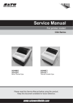
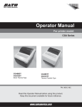
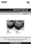
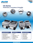
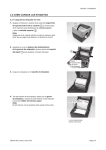
1
Service Manual For printer model: CG4 Series CG408DT CG412DT Direct Thermal Type CG408TT CG412TT Thermal Transfer Type PN: 9001219A Please read this Service Manual before using this product. Keep this document available for future reference. www.satoamerica.com SATO America, Inc. 10350A Nations Ford Road Charlotte, NC 28273 Main Phone: (704) 644.1650 Technical Support: (704) 644.1660 Technical Support Fax: (704) 644.1661 E-Mail: [email protected] [email protected] www.satoamerica.com Copyright 2010 SATO America, Inc. All rights reserved Caution (1) Reproduction in any manner of all or part of this document is prohibited. (2) The contents of this document may be changed without prior notice. (3) Great care has been taken in the preparation of this document. However, if, for any reason, if any problems, mistakes, or omissions are found, please contact your SATO reseller or technical support center. PN: 9001219A Table of Contents Table of Contents Introduction ................................................................................................................ 1- 1 1.1 About this Manual ...........................................................................................................1-2 1.2 Features of the Printer.....................................................................................................1-2 1.3 Parts Identification...........................................................................................................1-3 General Specifications .............................................................................................. 2- 1 2.1 Printer Basic Specifications.............................................................................................2-1 2.2 Optional Accessories Specifications ...............................................................................2-7 Interface Specifications............................................................................................. 3- 1 3.1 Interface types.................................................................................................................3-1 3.2 RS232C Serial Interface..................................................................................................3-2 3.3 IEEE 1284 Parallel Interface ...........................................................................................3-8 3.4 Universal Serial Bus (USB) Interface ............................................................................3-14 3.5 Local Area Network (LAN) Ethernet ..............................................................................3-16 Operation and Configuration .................................................................................... 4- 1 4.1 Operator Panel ................................................................................................................4-2 4.2 Operating Modes.............................................................................................................4-3 4.3 User Test Print Mode ......................................................................................................4-6 4.4 Factory Test Print Mode ................................................................................................4-10 4.5 Operation Setting Mode ................................................................................................4-14 4.6 Program Download Mode..............................................................................................4-17 4.7 Font Download Mode ....................................................................................................4-19 4.8 Default Setting Mode.....................................................................................................4-20 4.9 HEX Dump Mode ..........................................................................................................4-21 4.10 Boot Download Mode ..................................................................................................4-22 4.11 Error Occurrence While Downloading .........................................................................4-23 4.12 Factory Clear Mode.....................................................................................................4-24 4.13 Factory Adjustment Mode ...........................................................................................4-27 4.14 Factory USB Interface Mode .......................................................................................4-31 4.15 Factory USB Boot Download Mode.............................................................................4-32 4.16 Printer Configurations Setting .....................................................................................4-33 Troubleshooting......................................................................................................... 5- 1 5.1 Error Signal Troubleshooting...........................................................................................5-2 5.2 Troubleshooting Flowchart ..............................................................................................5-4 5.3 Interface Troubleshooting..............................................................................................5-14 5.4 Test Print Troubleshooting ............................................................................................5-15 Checks and Adjustment Procedures ....................................................................... 6- 1 6.1 Checking the Power Supply ............................................................................................6-2 6.2 Automatic Adjustment of I-Mark and GAP Sensor Outputs.............................................6-4 6.3 Sensor checks.................................................................................................................6-5 6.4 Ribbon Tension Adjustment (For CG408TT, CG412TT only) .........................................6-7 6.5 Pitch position Adjustment ................................................................................................6-8 6.6 Offset position Adjustment ..............................................................................................6-9 6.7 Print Darkness Adjustment............................................................................................6-10 CG4 Series Service Manual Page i Table of Contents Replacement Procedures.......................................................................................... 7- 1 7.1 Print Head Replacement .................................................................................................7-2 7.2 Platen Roller Replacement..............................................................................................7-5 7.3 Removal of the Bottom Housing cover............................................................................7-6 7.4 DC Power Terminal Board Replacement ........................................................................7-7 7.5 Main Circuit Board Replacement.....................................................................................7-8 7.6 Operator Panel (KB) Board Replacement .......................................................................7-9 7.7 Top Cover Open Sensor Replacement .........................................................................7-12 7.8 Stepper Motor Replacement .........................................................................................7-13 7.9 I-Mark/Gap Sensor Replacement..................................................................................7-14 7.10 Ribbon End Sensor Replacement ...............................................................................7-16 7.11 Torque Limiter (Supply Unit) Replacement .................................................................7-17 7.12 Torque Limiter (Ribbon Wind-up Unit) Replacement ..................................................7-18 7.13 Cutter Kit/ Board/Unit Replacement (Optional) ...........................................................7-19 7.14 Dispenser Kit/ Roller/ Label Sensor Replacement (Optional) .....................................7-21 7.15 Linerless (Non sepa) Label Sensor Replacement (Optional) ......................................7-23 7.16 Real Time Clock Battery Replacement (Optional).......................................................7-24 Appendix..................................................................................................................... 8- 1 8.1 Optional Accessories - Cutter..........................................................................................8-2 8.2 Optional Accessories - Dispenser ...................................................................................8-5 8.3 Optional Accessories - Linerless .....................................................................................8-8 8.4 Optional Accessories - Real Time Clock (RTC) Kit .......................................................8-10 8.5 Positions of sensors and options...................................................................................8-11 8.6 Operation Mode Selection.............................................................................................8-12 8.7 Base Reference Point ...................................................................................................8-13 8.8 Paper End .....................................................................................................................8-15 8.9 Ribbon End ...................................................................................................................8-16 Sato Group of Companies......................................................................................... 9- 1 Sato Group of Companies.....................................................................................................9-2 Page ii CG4 Series Service Manual Section 1: Introduction INTRODUCTION CG4 Series Service Manual Page 1-1 Section 1: Introduction 1.1 ABOUT THIS MANUAL This service manual provides all of the information required for printer maintenance and repair by SATO approved personnel. For the repair technician, this manual is intended to compliment, and to be used as an extension of operator manual. This manual also incorporates the use of special information boxes. Examples of these boxes and the type of information provided in each, are below. WARNING: PROVIDES INFORMATION THAT, IF UNHEEDED, MAY RESULT IN PERSONAL INJURY. CAUTION: PROVIDES INFORMATION THAT, IF UNHEEDED, MAY RESULT IN EQUIPMENT DAMAGE. NOTE: Provides helpful hints to assist in performing the tasks at hand. A comprehensive Table Of Contents provided at the front of this manual facilitates rapid movement within. The contents identify the different unit sections and their respective sub-sections. Each references the page number of their commencement. The pages of this manual has embedded headers and footers to assist the user in identifying his or her exact position within the manual. The header provides the section number followed by its name. The footer identifies the product and the page number. Page enumeration is two-part with each separated by a hyphen. The first character set references the section number and the second identifies the page number. Page numbers begin with the numeral (1) one at the commencement of a new section and ascends sequentially. 1.2 FEATURES OF THE PRINTER The CG4 Series is 4 inch Compact Desktop printer (Thermal Transfer or Direct Thermal). With a 32-bit RISC CPU, 4 ips print speed, and 4MB Flash Memory, the CG4 Series is an economical printer with numerous features making it suitable for a wide range of applications. The key features of the CG4 Series are: • • • • • • • • • • • Page 1-2 High Print Resolution with crisp printing quality (203dpi or 305dpi) Multiple Interface Cutter and Dispenser Printer Options Linerless Label Support Easy Media Loading Standalone Capability using Keypad Tool-less changing of print head and platen roller for easier maintenance Codepage Support and Emulations Anti-Microbial casing is ideally suited for clinical environments or food processing industry Safety Top Cover Latch Distinctive Chassis color CG4 Series Service Manual Section 1: Introduction 1.3 PARTS IDENTIFICATION Front view 1 5 6 2 7 3 8 4 1 2 Operator panel 7 It consists of two contact buttons and two LED indicators (green and red). The LED lights or blinks red when an error is detected in the printer. Top cover During printer configuration setting, the ERROR indicator responses in conjunction with the ON LINE (POWER) indicator to show the modes of the printer. Open this cover to load the media and ribbon. 3 Cover open/close latch Pull these latches on both sides of the printer forward to open the Top cover of the printer. 4 Media ejection slot Opening for media output. 5 POWER button Press this button to turn the power on or off. 6 ERROR LED indicator 8 ON LINE (POWER) LED indicator The LED lights green when the printer is online and blinks green when the printer is offline. During printer configuration setting, the ON LINE (POWER) indicator responses in conjunction with the ERROR indicator to show the modes of the printer. FEED/LINE button Press this button to select the printer status (online/ offline) or to feed the media. CG4 Series Service Manual Page 1-3 Section 1: Introduction 1.3 PARTS IDENTIFICATION (cont’d) Back view USB and RS232C interface on-board 10 11 12 USB and LAN interface on-board 10 11 9 13 USB and IEEE interface on-board 10 14 11 9 Media inlet 13 To connect printer to the host computer using LAN interface. An opening for Fan-folded media or media from unwinder to feed in to the printer. 10 DC input power terminal Supplies power to the printer by inserting the power cable via the AC adapter. 11 LAN interface terminal 14 IEEE interface terminal To connect printer to the host computer using IEEE interface. USB interface terminal To connect printer to the host computer using the USB interface. 12 RS-232C interface terminal To connect printer to the host computer using RS-232C interface. Or, to connect the optional Keypad, Scanner or Smart keyboard to the printer. Page 1-4 CG4 Series Service Manual Section 1: Introduction 1.2 PARTS IDENTIFICATION (cont’d) Internal view when Top cover is opened 15 15 16 17 18 18 19 20 20 19 21 21 22 22 CG408TT/ CG412TT 15 Print head This component is used to print on the media. Perform maintenance at regular intervals. 16 Ribbon unit CG408DT/ CG412DT 19 Set to meet the size of the media used. 20 Pull out lever This is used to pull out the ribbon unit from the top cover for ribbon loading. 18 Roll media holder To hold the roll media. CG4 Series Service Manual Media guide and I-Mark/ Gap sensor A guide for the media to feed properly. Used to load the ribbon and wind up the used ribbon. 17 Media guide slide lever Detects the I-Mark on the media or gap of the label. 21 Platen roller This roller feeds the media. Perform maintenance at regular intervals. 22 Optional device compartment Used to install optional cutter, dispenser or linerless unit. Page 1-5 Section 1: Introduction This page is intentionally left blank Page 1-6 CG4 Series Service Manual Section 2: General Specifications GENERAL SPECIFICATIONS 2.1 PRINTER BASIC SPECIFICATIONS MODEL NAME CG408 DT CG412 DT CG408 TT CG412 TT PHYSICAL CHARACTERISTICS Width 7.05” (179 mm) Depth 9.37” (238 mm) Height 6.81” (173 mm) Weight 3.7 lbs. (1.7 kg) 4.19 lbs. (1.9 kg) POWER SUPPLY (AC ADAPTER) Input Voltage 100-240 V AC, +/-10%, 50/60 Hz (Full range) Output Voltage 19 V DC, +/-5%, 3.86A Power Consumption At peak times: 50 Watts During standby: 2.5 Watts ENVIRONMENTAL (EXCLUDING MEDIA) Operating Temperature 4° to 38°C (39.2 to 100.4°F) Storage Temperature -10° to 60°C (14 to 140°F) Operating Humidity 30 to 80% RH, Non-condensing Storage Humidity 15 to 85% RH, Non-condensing PRINT Method Print Speed (selectable) Resolution DT models: Direct Thermal only TT models: Thermal Transfer and Direct Thermal 2, 3 or 4 Inches/second (Setting: 2, 3, 4) 50, 75 or 100 mm/second *Maximum print speed varies depending on the of media used. 203 Dots Per Inch (8 dots/mm) 305 Dots Per Inch (12 dots/mm) 203 Dots Per Inch (8 dots/mm) Maximum Print Width 4.09” (104 mm) Maximum Print Length 11.81” (300 mm) CG4 Series Service Manual 305 Dots Per Inch (12 dots/mm) Page 2-1 Section 2: General Specifications MODEL NAME CG408 DT/ CG408TT CG412 DT/ CG412TT MEDIA (BE SURE TO USE MEDIA MANUFACTURED OR CERTIFIED BY SATO) Type Direct Thermal / Thermal Transfer depending on print model (DT or TT) Roll stock or Fan-fold Wind Direction Roll and Core Diameter Roll stock: Face In or Face out winding Maximum outer diameter: 5.04” (128 mm) with Inner core diameter: 1.5” (40 mm) * Inner core diameter: 0.75” (19.05 mm) with maximum outer diameter: 4.33” (110 mm) can be accepted, but there is no performance guarantee. Fanfold Max. stack height 4.65” (118 mm) (external supply) Label Continuous Pitch: 0.27” to 11.8” (7 to 300 mm) Pitch including liner: 0.39” to 11.93” (10 to 303 mm) Width: 0.86” to 4.21” (22 to 107 mm) Width including liner: 0.98” to 4.33” (25 to 110 mm) Cutter Pitch: 0.87” to 11.8” (22 to 300 mm) Pitch including liner: 0.98” to 11.93” (25 to 303 mm) Width: 0.87” to 4.21” (22 to 107 mm) Width including liner: 0.98” to 4.33” (25 to 110 mm) Dispenser Pitch: 0.87” to 3.93” (22 to 100 mm) Pitch including liner: 0.98” to 4.05” (25 to 103 mm) Width: 0.87” to 4.21” (22 to 107 mm) Width including liner: 0.98” to 4.33” (25 to 110 mm) Tear-off Size Linerless Pitch: 0.87” to 11.8” (22 to 300 mm) *1 Pitch including liner: 0.98” to 11.93” (25 to 303 mm) Width: 0.87” to 4.21” (22 to 107 mm) Width including liner: 0.98” to 4.33” (25 to 110 mm) Pitch: 0.98” to 3.93” (25 to 100 mm) *1 With: 0.98” to 4.33” (25 to 110 mm) Non-adhesive paper Continuous Pitch: 0.39” to 11.93” (10 to 303 mm) *1 Width: 0.98” to 4.33” (25 to 110 mm) Cutter Pitch: 0.98” to 11.93” (25 to 303 mm) Width: 0.98” to 4.33” (25 to 110 mm) Pitch: 0.98” to 11.93” (25 to 303 mm) *1 Width: 0.98” to 4.33” (25 to 110 mm) Tear-off *1 Media using small pitch must be torn by hand. • The above size may be limited by use conditions, such as type of paper, usage environment, and application. • When using the dispenser mode, restrictions apply to the maximum paper length according to paper installation conditions. Thickness Page 2-2 0.0024” to 0.0074” (0.06 to 0.19 mm ) CG4 Series Service Manual Section 2: General Specifications MODEL NAME CG408 DT CG412 DT CG408 TT CG412 TT RIBBON (BE SURE TO USE RIBBON MANUFACTURED OR CERTIFIED BY SATO) Wind Direction Face Out Winding Method Paper core Roll Diameter Maximum outer diameter: 1.4” (38 mm) Core Diameter Inner core diameter: 0.5” (12.7 mm) — Max. 328 ft. (100 m) , Do not exceed the maximum outer diameter. Length Use only 4.33” +/- 0.01” (110 mm +/- 0.5 mm ) Width PROCESSING CPU 32 Bit RISC-CPU 133MHz Flash ROM 4 Megabytes SDRAM 8 Megabytes PRINTER LANGUAGE Standard SATO Barcode Printer Language (SBPL) INTERFACES Standard Configurations Select one of the following. (The factory will provide the unit with the selected interface.) 1) USB 2.0 (Type B) with RS-232C (D-SUB 9-pin type) or 2) USB 2.0 (Type B) with LAN (10BASE-T/100BASE-TX Automatic Switching) or 3) USB 2.0 (Type B) with IEEE1284 *The RS-232C connector can be used to connect the printer to a computer, an optional keypad, Smart keyboard or Barcode scanner. SENSING Gap (Transmissive) Sensitivity Adjustable I-Mark (Reflective) Sensitivity Adjustable Cover Open Fixed Ribbon End Not available Fixed (Only available for Thermal Transfer model) Dispenser Fixed (Only available if installed) Linerless label sensor Fixed (Only available if installed) LABEL ISSUING MODES Standard: Continuous mode, Tear -off mode, Sensor off mode Optional mode: Dispenser mode, Cutter mode, Linerless mode CG4 Series Service Manual Page 2-3 Section 2: General Specifications MODEL NAME CG408 DT CG412 DT CG408 TT CG412 TT SELF-DIAGNOSIS Cover Open Detection Paper End Detection Test Print Cutter error (Only available if installed) Cover Open Detection Paper Detection Test Print Ribbon end Detection Cutter error (Only available if installed) CHARACTER FONT CAPABILITIES BITMAP FONTS U 5 dots W x 9 dots H (Alphanumeric characters and symbols) S 8 dots W x 15 dots H (Alphanumeric characters and symbols) M 13 dots W x 20 dots H (Alphanumeric characters and symbols) WB 18 dots W x 30 dots H (Alphanumeric characters and symbols) WL 28 dots W x 52 dots H (Alphanumeric characters and symbols) XU 5 dots W x 9 dots H (Alphanumeric characters and symbols) XS 17 dots W x 17 dots H (Alphanumeric characters and symbols) XM 24 dots W x 24 dots H (Alphanumeric characters and symbols) XB 48 dots W x 48 dots H (Alphanumeric characters and symbols) XL 48 dots W x 48 dots H (Alphanumeric characters and symbols) OA Font (OCR-A) 15 dots x 22 dots (Alphanumeric characters and symbols) 22 dots x 33 dots (Alphanumeric characters and symbols) 15 dots x 22 dots (Alphanumeric characters and symbols) 22 dots x 33 dots (Alphanumeric characters and symbols) OB Font (OCR-B) 20 dots x 24 dots (Alphanumeric characters and symbols) 30 dots x 36 dots (Alphanumeric characters and symbols) 20 dots x 24 dots (Alphanumeric characters and symbols) 30 dots x 36 dots (Alphanumeric characters and symbols) KANJI FONTS Supported by downloading one of the following kanji fonts. 1) Simplified Chinese (2.6MB) Gothic type GB2312 (24 x 24 dot) 2) Korean (1.6MB) Gothic type KSX1001 (16 x 16 dot) Mincho type KSX1001 (24 x 24 dot) OUTLINE FONTS Alphanumeric characters and symbols CHARACTER CONTROL Page 2-4 Magnification Expansion up to 12 x in either the vertical or horizontal Rotation 0°, 90°, 180° and 270° CG4 Series Service Manual Section 2: General Specifications MODEL NAME CG408 DT CG412 DT CG408 TT CG412 TT BARCODE CAPABILITIES Linear Bar Codes UPC-A/UPC-E, EAN8/13, CODE39, CODE93, CODE128, GS1-128 (UCC/EAN128), CODABAR(NW-7), ITF, Industrial 2 of 5, Matrix 2 of 5, BOOKLAND, MSI, POSTNET, GS1 DataBar (RSS) * GS1 DataBar is new version of RSS-14. Two Dimensional codes PDF417 (Ver.2.4), MAXI code (Ver.3.0), QR code, GS1 DataMatrix (ECC200) Composite Symbols EAN-13 Composite (CC-A/CC-B) EAN-8 Composite (CC-A/CC-B) UPC-A Composite (CC-A/CC-B) UPC-E Composite (CC-A/CC-B) GS1-128 Composite (CC-A/CC-B/CC-C) GS1 DataBar Composite (CC-A/CC-B) GS1 DataBar Truncated Composite (CC-A/CC-B) GS1 DataBar Stacked Composite (CC-A/CC-B) GS1 DataBar Stacked Omni-Directional Composite (CC-A/CC-B) GS1 DataBar Limited Composite (CC-A/CC-B) GS1 DataBar Expanded Composite (CC-A/CC-B) GS1 DataBar Expanded Stacked Composite (CC-A/CC-B) * GS1 DataBar is new version of RSS-14. Ratios 1:2, 1:3, 2:5, User definable bar widths Magnification 1 x to 12 x Rotation Parallel 1 (0°), Parallel 2 (180°), Serial 1 (90°) and Serial 2 (270°) STANDARD FUNCTIONS 1) Status return function 2) Graphic function 3) Sequential number function 4) Form overlay function 5) Custom character registration function 6) Black/white inversion function 7) Ruled line function 8) Format registration function 9) Zero slash switching function CG4 Series Service Manual Page 2-5 Section 2: General Specifications MODEL NAME CG408 DT CG412 DT CG408 TT CG412 TT HARDWARE AND RELATED Operation keys POWER and FEED/LINE buttons Indicators ON LINE (POWER): Green LED ERROR: Red LED Buzzer Built-in buzzer • On/ off switchable buzzer (specified by command) • No volume control function available Surface Treatment Antibacterial finishing for external cover and operative parts. Tested according to JIS Z 2801 standard OPTIONS 1) Cutter Unit 2) Dispenser Unit 3) RTC kit (Calendar IC) 4) Linerless Unit 5) Keypad* 6) Compatible smart keyboard* 7) Compatible 1D barcode scanner* *Applicable to USB and RS232C interface model only. Connect to RS232C terminal. REGULATORY COMPLIANCE Safety regulation UL60950-1(2001) (USA) CSA22.2 No.60950-1-30 (Canada) EN60950-1, CE (Europe) CCC (GB4943-2001) (China) EMC regulation FCC15B Class B (USA/Canada) CE (EN55022, EN55024) (Europe) GB9254-1998, GB17625.1(2003) (China) KN22, KN24 (Korea) Packing Drop Standard ISTA-2A Environmental (RoHS) Chromium: below 0.1% Lead: below 0.1% Mercury: below 0.1% Cadmium: below 0.01% Polybrominated Biphenyl (PBB): below 0.1% Polybrominated Diphenyl Ether (PBDE): below 0.1% Page 2-6 CG4 Series Service Manual Section 2: General Specifications 2.2 OPTIONAL ACCESSORIES SPECIFICATIONS CUTTER SPECIFICATIONS Media Type Non-adhesive paper and Label Pitch: 0.87” to 11.8” (22 to 300 mm) Pitch including liner: 0.98” to 11.93” (25 to 303 mm) Media Size Width: 0.87” to 4.21” (22 to 107 mm) Width including liner: 0.98” to 4.33” (25 to 110 mm) Thickness 0.0024” to 0.0074” (0.06 to 0.19 mm) Self-diagnosis function Cutter error detection Durability More than 300,000 cuts DISPENSER SPECIFICATIONS Label only Media Type * Some restrictions may apply to some label types depending on the substrate, adhesive, paper size, and environment. Refer to SATO representative on the labels to be used. * Perforated liner and split liner cannot be used. * Peel end labels Pitch: 0.86” to 3.93” (22 to 100 mm) Pitch including liner: 0.98” to 4.05” (25 to 103 mm) Media Size Width: 0.86” to 4.21” (22 to 107 mm) Width including liner: 0.98” to 4.33” (25 to 110 mm) Thickness 0.0024” to 0.0074” (0.06 to 0.19 mm) Sensor Type Dispenser sensor (Reflective type) LINERLESS KIT SPECIFICATIONS Media Type Micro-perforated Linerless Label Media Size Pitch: 0.98” to 3.93” (25 to 100 mm) With: 0.98” to 4.33” (25 to 110 mm) Thickness 0.0024” to 0.0074” (0.06 to 0.19 mm) Media Winding direction Face-out Roll and core Diameter Maximum outer diameter: 5.04” (128 mm) with Inner core diameter: 1.5” (40 mm) Sensor Type Label sensor (Reflective type) Label issuing mode Continuous mode, Tear-off mode CG4 Series Service Manual Page 2-7 Section 2: General Specifications This page is intentionally left blank Page 2-8 CG4 Series Service Manual Section 3: Interface Specifications INTERFACE SPECIFICATIONS This section presents the interface types and their specifications for the CG4 Series printers. These specifications include detailed information to assist in the selection of the most appropriate method for the printer to interface with the host. The following information is presented in this section: • • • • • 3.1 Interface types 3.2 RS232C Serial Interface 3.3 IEEE 1284 Parallel Interface 3.4 Universal Serial Bus (USB) Interface 3.5 Local Area Network (LAN) Ethernet 3.1 INTERFACE TYPES The CG4 Series has three types of Main PCBs. Each type of PCB is equipped with two different interface types for performing data communication with the host. These are described as follows. 1) Type 1: USB and LAN on-board 2) Type 2: USB and RS232C on-board 2) Type 3: USB and IEEE1284 on-board Interface Types Model USB LAN RS232C IEEE1284 CG4 series (Type 1) Yes Yes - - CG4 series (Type 2) Yes - Yes - CG4 series (Type 3) Yes - - Yes CAUTION: Never connect or disconnect interface cables (or use a switch box) with power applied to either the host or printer. This may caused damage to the interface circuitry in the printer/ host and is not covered by warranty. CG4 Series Service Manual Page 3-1 Section 3: Interface Specifications 3.2 RS232C SERIAL INTERFACE 3.2.1 Basic Specifications of RS-232C Serial Interface This interface complies with the RS-232C standard. Interface connector DB-9S or equivalent (Male) Cable length: 5m or less Communication settings Use Printer configuration tool or <I2> command to setup. <I2>abcde Parameter Item Value Description a Baud rate 2 38400bps 1 19200bps [Default] 0 9600bps Data bit length 1 7 bits 0 8 bits [Default] Parity bits 2 EVEN 1 ODD 0 NONE [Default] 1 2 bits 0 1 bit [Default] 4 STATUS 3 3 Protocol for driver (STATUS 4) [Default] 2 XON/XOFF 1 READY/BUSY (Multi item buffer) 0 READY/BUSY (Single item buffer) b c d e Page 3-2 Stop bits Protocol CG4 Series Service Manual Section 3: Interface Specifications 3.2 RS232C SERIAL INTERFACE (cont’d) Function descriptions Function Description Baud rate setting Select the data rate (bps) for the RS232 port. Data bit length Sets the printer to receive either 7 or 8 bits of data for each byte transmitted. Parity setting Selects the type of parity used for error detection. Stop bit setting Selects the number of stop bits to end each byte transmission. Protocol setting Selects the flow control and status reporting protocols Synchro system Asynchronous method Maximum receive buffer capacity 1MB 1MB 0MB Buffer near full occurred Remaining 0.25MB Buffer near full released Remaining 0.5MB Code ASCII (7 bits), Graphic (8 bits) Transmission form Start b1 b2 b3 b4 b5 b6 b7 b8 Stop [Note] If using 7 bits, b8 will be omitted. Signal level High level Low level Interface type Use Printer configuration tool or <DI> command. <DI>a CG4 Series Service Manual : +5 to +12V : -5 to -12V Parameter Item Value Description a Interface selection 0 USB 1 RS-232C 2 Keypad 3 Scanner/ Smart keyboard Page 3-3 Section 3: Interface Specifications 3.2 RS232C HIGH SPEED SERIAL INTERFACE (cont’d) 3.2.2 Ready/Busy This protocol controls the reception of print data only by the control of hardware signal. Use the command <I2> to toggle between single item buffer and multi item buffer. When the print data (STX ESC+”A”~ ESC+”Z” ETX) is sent from the host in the conditions below, received data may be incorrect. 1) When the printer is Offline 2) When an error has occurred in the printer Pin Assignments 1)Host with DB-25P terminal Printer CD 1 RD 2 SD 3 ER 4 SG 5 DR 6 RS 7 CS 8 RI 9 Host 1 2 3 6 7 20 5 4 FG SD RD DR SG ER CS RS 2)Host with DB-9P terminal Printer CD 1 RD 2 SD 3 ER 4 SG 5 DR 6 RS 7 CS 8 RI 9 Host 1 3 2 6 5 4 8 7 9 CD SD RD DR SG ER CS RS RI Interface Signals Pin no. Signal Type Direction Description 2 RD Input Data transferred from the host to the printer 3 SD Output Data transferred from the printer to the host 4 ER Output Data terminal READY 5 SG - Signal ground 6 DR Input Data set READY 7 RS Output Send request 8 CS Input READY to send Notes: Follow the procedures below when executing READY/BUSY control. 1)When the host sends the data for printing labels, make sure that the printer is on. 2)Turning the printer on after the printer receives a request from the host to print labels may cause the printer not to print the first print data (approximately 120 bytes). To avoid this problem, it is necessary to attach approximate 120 bytes of dummy data by application software that enables the host to send the data for printing labels. For example: When sending [STX+<A>+<V>20+<H>20+<P>2+<L>0202+<X20>, 1234+<Q>2+<Z>+ETX], transfer the appropriate 120 bytes of dummy data shown below. [00H+00H+ ~ +00H+00H+00H+00H] + [STX ~ ETX] Page 3-4 CG4 Series Service Manual Section 3: Interface Specifications 3.2 RS232C HIGH SPEED SERIAL INTERFACE (cont’d) Timing Chart (Single item buffer) (1) Normal process Press the FEED/LINE button Power ON Printer side ER Initial Press the FEED/LINE button td td STX..ETX(1) RD ETX(2) …….. STX RS Online Printer status Online Offline Receiving/Analysis/Editing(1) Receiving/Analysis/Editing(2) Print(2) Print(1) td: It takes the printer approx. 10μs to recognize the end of item and to start controlling ER. (2) Error process Head open Printer side Head close Press the FEED/LINE button td ER STX..ETX(1) RD RS Offline Printer status Online Online Offline Receiving/Analysis/Editing(1) * Print(1) Print(1) * When the paper end has occurred: Open the head Set the label Close the head for feed operation. NOTE: When the head is closed, the paper end will be released. Timing Chart (Multi item buffer) (1) Normal process Receive buffer near full occurred Power ON Printer side ER Press the FEED/LINE button Receive buffer near full release Initial STX..ETX(2) STX..ETX(1) RD STX …….. ETX(3) …….. STX ETX(4) RS Online Printer status Receiving/Analysis/Editing(1) Offline Receiving/Analysis/Editing(2) Receiving/Analysis/Editing(3) Receiving/Analysis/Editing(4) Print(2) Print(1) Online Print(3) NOTE: For multi buffer mode, it is possible to continue data communications while printing. (2) Error process Printer side Head open Head close Press the FEED/LINE button Press the FEED/LINE button Paper end ER RD STX …….. Online Offline STX ETX(1) ETX(2) …….. RS Printer status Offline Online Receiving/Analysis/Editing(1) Online Receiving/Analysis/Editing(2) Print(1) * Print(1) Print(2) * When the paper end has occurred: Open the head Set the label Close the head for feed operation. NOTE: When the head is closed, the paper end will be released. CG4 Series Service Manual Page 3-5 Section 3: Interface Specifications 3.2 RS232C HIGH SPEED SERIAL INTERFACE (cont’d) 3.2.3 X-ON/X-OFF This transmission protocol informs the host if the printer is ready to receive data, by sending the “XON” (Hex 11H) or “XOFF” (Hex 13H) code. When the print data (STX ESC+”A”~ ESC+”Z” ETX) is sent from the host in the conditions below, received data may be incorrect. 1) When the printer is Offline 2) When an error has occurred in the printer Pin Assignments 1) Host with DB-25P terminal Printer RD 2 SD 3 SG 5 2) Host with DB-9P terminal Printer RD 2 SD 3 SG 5 Host 2 3 7 SD RD SG Host 3 2 5 SD RD SG Note: Depending on the host used, it may need to loop CS and RS (maintaining at “High” level) on the host side. Therefore, make sure to re-check the host before use. Input/Output Signals Pin no. Signal Type Direction Description 2 RD Input Data transferred from the host to the printer 3 SD Output Data transferred from the printer to the host 5 SG - Signal ground Timing Chart (Multi item buffer) (1) Normal process Receive buffer near full occurred Power ON Printer side SD XON 500ms Initial XOFF XON STX..ETX(1) RD Press the FEED/LINE button Receive buffer near full released XON STX..ETX(2) XOFF XON STX.......ETX(4) STX..ETX(3) Offline Online Printer status Press the FEED/LINE button Receiving/Analysis/ Receiving/Analysis/ Receiving/Analysis/ Editing(1) Editing(2) Editing(3) Receiving/Analysis/Editing(4) Print(3) Print(2) Print(1) NOTE: In this protocol, executing the polling of “XON” at intervals of 500ms from the power supply to the first data reception. (2) Error process Head open Printer side Head close Press the FEED/LINE button XOFF SD STX XOFF XON …….. Press the FEED/LINE button Paper end occurred STX ETX(1) …….. XON XOFF ETX(2) RD Printer status Online Offline Online Offline Receiving/Analysis/Editing(1) Online Receiving/Analysis/Editing(2) Print(1) * Print(1) * When the paper end has occurred, Open the head Reset the label Close the head for feed operation. NOTE: When the head is closed, the paper end will be released. Data reception during the error ocurrence executes the transmission of “XOFF” Page 3-6 CG4 Series Service Manual Section 3: Interface Specifications 3.2 RS232C HIGH SPEED SERIAL INTERFACE (cont’d) 3.2.4 Return Status (STATUS 3 and Protocol for Driver (STATUS 4)) The purpose of these protocols is to control printer status on the host side. With the request command from the host, the status is returned from the printer. After receiving the request command, the status is returned immediately. In these communication protocols, receive mode is set to multi item buffer. When the print data (STX ESC+”A”~ ESC+”Z” ETX) is sent from the host in the conditions below, received data may be incorrect. 1) When the printer is Offline 2) When an error has occurred in the printer CG4 Series Service Manual Page 3-7 Section 3: Interface Specifications 3.3 IEEE 1284 PARALLEL INTERFACE 3.3.1 Basic Specifications of IEEE1284 parallel interface This interface complies with the Centronics/ IEEE1284 standard. ECP mode is recommended for LPT1 port. LPT1 port details can be set through a computer’s BIOS settings. Interface connector Printer side: Amphenol (DDK) 57 to 40360 or equivalent Cable side: Amphenol (DDK) 57 to 30360 or equivalent Cable length: 1.5m or less Signal level High level Low level : +2.4 to +5.0V : +0.0 to +0.4V Communication condition setting Use the <I1> command for the following settings. Item Color Receive mode Single item buffer Multi item buffer ACK width 010 to 200 (1=50ns) Communication protocol cannot be fixed at compatible mode because of IEEE1284 negotiation. Interface type Maximum receive buffer capacity Use Printer configuration tool or <DI> command. <DI>a Parameter Item Value Decription a Interface 0 USB 1 IEEE1284 1MB 0MB 1MB Buffer near full occurred Remaining 0.25MB Buffer near full released Remaining 0.5MB Page 3-8 CG4 Series Service Manual Section 3: Interface Specifications DeviceID CG408 “MFG:SATO;CMD:PCL,MPL;MDL:CG408;” CG412 “MFG:SATO;CMD:PCL,MPL;MDL:CG412;” CG4 Series Service Manual Page 3-9 Section 3: Interface Specifications 3.3 IEEE 1284 PARALLEL INTERFACE (cont’d) 3.3.2 Pin Assignments Pin assignment of each signal for the Centronics standard (Compatible Mode) is as follows. Note that the connection of the IEEE1284standard complies with the IEEE1284-B standard. PIN No. Signal I/O PIN No. Signal I/O 1 STROBE Input 19 STROBE-RETURN 2 DATA 1 Input 20 DATA 1-RETURN 3 DATA 2 Input 21 DATA 2-RETURN 4 DATA 3 Input 22 DATA 3-RETURN 5 DATA 4 Input 23 DATA 4-RETURN 6 DATA 5 Input 24 DATA 5-RETURN 7 DATA 6 Input 25 DATA 6-RETURN 8 DATA 7 Input 26 DATA 7-RETURN 9 DATA 8 Input 27 DATA 8-RETURN 10 ACK Output 28 ACK -RETURN 11 BUSY Output 29 BUSY -RETURN 12 PE Output 30 PE -RETURN 13 SELECT Output 31 INIT Input 14 AUTOFD Input 32 FAULT Output SELECTIN Input 15 33 16 LOGIC GND 34 17 CHASSIS GND 35 18 PERIPHERAL LOGIC HIGH Page 3-10 Output 36 CG4 Series Service Manual Section 3: Interface Specifications 3.3 IEEE 1284 PARALLEL INTERFACE (cont’d) 3.3.3 Input/Output Signals The details of each signal line for the Centronics standard (Compatible Mode) are as follows. Note that each signal line complies with the IEEE1284 standard. Signal I/O Description STROBE Input Synchronization signal that requires low active pulse to read DATA1 ~ DATA8 DATA 1 ~ DATA 8 Input Data entry of 8bits parallel: DATA1 --LSB (lowest bit) DATA8 --MSB (highest bit) ACK Output Low active pulse signal indicating the completion of receive data import BUSY Output High active signal indicating that the printer is not ready to receive data PE Output High active signal indicating paper shortage SELECT Output High active signal indicating that the printer is ready to receive data AUTOFD Input Signal for the IEEE1284 standard CHASSIS GND PERIPHERAL LOGIC HIGH Connecting to framework ground Output SIGNAL GND +5V voltage on the printer side Connecting to each signal ground INIT Input Low active pulse signal requesting to reset the printer FAULT Output Low active pulse signal indicating an error in the printer SELECTIN Input Signal for the IEEE1284 standard CG4 Series Service Manual Page 3-11 Section 3: Interface Specifications 3.3 IEEE 1284 PARALLEL INTERFACE (cont’d) Timing Chart (Single item buffer) 1) Normal process Press FEED/LINE Power ON Printer side DATA Initial ESC A…ESC Z(1) Press FEED/LINE ESC A……ESC Z(2) STROBE ACK BUSY SELECT TX PE FAULT Offline Online Printer status Online Receiving/Analysis/Editing(2) Receiving/Analysis/ Editing(1) Print(2) Print(1) *TX<5ms> [Important] Turning the printer off when sending a continuous job will result in the lack of subsequent job. (16 bytes after the command [ESC+Z] is maintained in the printer, but the next job of 16 bytes will be cleared by turning the printer off.) 2) Process of paper end occurrence Paper end occurred Head close Head open Press FEED/LINE Printer side DATA ESC A……ESC Z(1) STROBE ACK BUSY SELECT PE FAULT Printer status Offline Online Online Receiving/Analysis/Editing(1) Print(1) * NOTE: (1) When the paper end has occurred, Open the print head assembly Reset the label (2) When the print head assembly is closed, the paper end will be released. Page 3-12 Print(1) Close the print head assembly for feed operation. CG4 Series Service Manual Section 3: Interface Specifications 3.3 IEEE 1284 PARALLEL INTERFACE (cont’d) Timing Chart (Multi item buffer) 1) Normal process Power ON Press FEED/LINE Printer side DATA Initial ESC A…ESC Z(2) ESC A…ESC Z(1) Receive buffer near full occurred Press FEED/LINE Receive buffer near full release ESC A…ESC Z(3) STROBE ACK BUSY SELECT PE FAULT Offline Online Printer status Receiving/Analysis/ Editing(1) Online Receiving/Analysis/ Editing(2) Receiving/Analysis/ Editing(3) Print(2) Print(1) Print(3) 2) Process of paper end occurrence Paper end occurred Head close Head open Press FEED/LINE Printer side DATA ESC A……ESC Z(1) ESC A……ESC Z(2) STROBE ACK BUSY SELECT PE FAULT Printer status Offline Online Receiving/Analysis/Editing(1) Print(1) NOTE: (1) When the paper end has occurred, Open the print head assembly Reset the label (2) When the print head assembly is closed, the paper end will be released. CG4 Series Service Manual Online Receiving/Analysis/Editing(2) Print(1) Close the print head assembly for feed operation. Page 3-13 Section 3: Interface Specifications 3.4 UNIVERSAL SERIAL BUS (USB) INTERFACE This printer supports the USB 2.0-compliant interface and the transfer rate at 12.5 Mbits/second. 3.4.1 Basic Specifications of USB interface The USB interface is available with all three types of boards. Interface connector Series B plug Cable length: 5m or less (Twisted Pair Shielded) Version USB 2.0 Maximum receive buffer capacity 1MB 1MB 0MB Buffer near full occurred Remaining 0.25MB Buffer near full released Remaining 0.5MB Interface type Use Printer configuration tool or <DI> command. <DI>a Parameter Item Value Description a Interface 0 USB 1 RS-232C/LAN/IEEE1284 2 Keypad 3 Scanner/ Smart keyboard 3.4.2 Pin Assignments Pin No. Description 1 VBus 2 -Data(D-) 3 +Data(D+) 4 GND Page 3-14 CG4 Series Service Manual Section 3: Interface Specifications 3.4 UNIVERSAL SERIAL BUS (USB) INTERFACE (cont’d) 3.4.3 Host Computer Settings Installation of USB Standard Print Support It is necessary to install the USB driver in addition to the printer driver to perform print operation via the USB port. As for the USB driver installation procedure, refer to [How to Install the USB Standard Print Support] in the printer driver installation specifications. Notes • • • OS environment corresponding to the USB interface is [Windows2000/XP/Server2003/Vista], however, the connection may not be established depending on the manufacturers or models. For more details, refer to your host computer documentation. USB cable length under 1m is recommended. Device name of USB port should be "Serial number". For example: CRGY0032 CG4 Series Service Manual Page 3-15 Section 3: Interface Specifications 3.5 LOCAL AREA NETWORK (LAN) ETHERNET 3.5.1 Basic Specifications of LAN A Local Area Network (LAN) interface requires a driver shipped with each printer that has the interface installed. The driver must be loaded on the host computer and configured to run one of the supported network protocols using a 10/100BaseT LAN connection. Interface connector Cable type: For 10BASE-T and 100BASE-TX Cable length: 100m or less Link/Status LED Status LED lights up when establishing the LINK with Ethernet equipment. The LINK is established by Auto Negotiation. LED Color Conditions LINK Green Lights up when establishing the LINK SPEED Orange Lights off when recognizing the destination 10BASE-T Lights up when recognizing the destination 100BASE-TX COLLISION Red Lights up when collision occurs Maintenance function [Printing LAN configuration information] LAN configuration information will be printed on the third sheet of user test print and factory test print. [Initializing LAN configuration information] LAN configuration information will be initialized through [All Clear] of Factory Clear Mode. For more details, refer Section 4.12 Factory Clear Mode. Interface type Use Printer configuration tool or <DI> command. <DI>a Page 3-16 Parameter Item Value Decription a Interface 0 USB 1 LAN CG4 Series Service Manual Section 3: Interface Specifications 3.5 LOCAL AREA NETWORK (LAN) ETHERNET (cont’d) Communication configuration The following settings can be configured via the Printer configuration tool or commands. Item Command Setting range LAN mode <I3> Protocol for driver (STATUS4) cyclic response mode *1 Protocol for driver (STATUS4) ENQ response mode *1 STATUS3 *2 [Coding example] To set the protocol for driver (STATUS4) cyclic response mode, send the following command to printer: <A> <I3>0 <Z> IP address <W1> 0.0.0.0 ~ 255.255.255.255 Subnet mask <W2> 0.0.0.0 ~ 255.255.255.255 Gateway address <W3> 0.0.0.0 ~ 255.255.255.255 IP address setup <WI> Manual DHCP RARP <WM> RARP disabled RARP enabled 2-port connection by Port1024 and Port1025 or 1 port connection by Port9100. 1 port connection by Port1024 or Port9100. *1 *2 Note: Please refer to the Command specification for more details in Sending commands. Maximum receive buffer capacity 1MB 0MB 1MB Buffer near full occurred Remaining 0.25MB Buffer near full released Remaining 0.5MB 3.5.2 Software Specifications ProtocolTCP/IP Network layerARP, RARP, IP, ICMP Session layerTCP, UDP Application layerLPR, FTP, TELNET, BOOTP, DHCP, HTTP Notes CG4 Series Service Manual Page 3-17 Section 3: Interface Specifications • • Send the print data by LPR and FTP of TCP/IP and dedicated socket protocol. (STATUS3, Protocol for driver (STATUS4)) Use socket connection to get the printer status. Page 3-18 CG4 Series Service Manual Section 3: Interface Specifications 3.5 LOCAL AREA NETWORK (LAN) ETHERNET (cont’d) 3.5.3 TCP/IP Specifications In TCP/IP protocol environment, LPD and FTP are provided for printing. TELNET is provided for the setup of various variables, and ARP, RARP and BOOTP/DHCP for the setup of IP address are available. In socket connection, the printing operation and the status are monitored. In this case, multiple connections cannot be established at the same time. WindowsNT and Windows2000/XP/Server2003/Vista operating system support LPD of TCP/IP that enables you to print; however, Windows98/Me is not configured with LPD. In order to perform printing operation, offthe-shelf printing software is required. 3.5.4 LPD Specifications LPD protocol complies with RFC1179 and handles the list of logical printer name as queue name such as lp, sjis and euc. Queue name Kanji filter applied Input Kanji code lp Not available N/A sjis Available Shift JIS euc Available EUC When sending a job by LPR, the transmission order of data file/control file within the job does not affect the printing operation. Notes • • • A job deletion by LPR is not supported. LPD is available only for Protocol for Driver (STATUS4). If executing a large quantity of printing by LPD, some parts of the data may be missing due to the Windows specification. 3.5.5 FTP Specifications FTP protocol complies with RFC959 and handles the list of logical printer name as transfer directory. File transfer to this directory executes printing operation. Note that it is possible to specify ASCII(A), BINARY(I), and TENEX(L8) as transfer modes although mode difference is dependent on the client side. There are three directory names such as lp, sjis and euc. Queue name Kanji filter applied Input Kanji code lp Not available N/A sjis Available Shift JIS euc Available EUC CG4 Series Service Manual Page 3-19 Section 3: Interface Specifications 3.5 LOCAL AREA NETWORK (LAN) ETHERNET (cont’d) 3.5.6 TELNET Specifications TELNET complies with RFC854. This consists of an interactive menu form, and it enables you to change and refer internal setup and to display status. To change the setting details, enter 'root' user name and password at the time of login. Default ROOT password is set to null (line feed only). <TELNET command example> In MS-DOS command prompt, type in [TELNET xxx.xxx.xxx.xxx (IP address)] and enter user name and password to advance to the display below. SATO PRINTER ModelName TELNET server. Copyright 2006(C) SATO Corporation. login: root ‘root’ user needs password to login password: User ‘root’ logged in No. Item Value (level.1) --------------------------------------------------------------------------------------1 : Setup TCP/IP 2 : Display status 99 : Exit setup Please select(1-99)? Each printer model name will appear in [Model Name]. For the detailed settings of [1:Setup TCP/IP], refer to Section 3.5.7 Setting/Displayed Items. 3.5.7 Setting/Displayed Items The following table shows the settings and referable sections as well as various variables. TCP/IP related settings Variable identifier Default (Factory setting) Setting range IP address 0.0.0.0 (Externally obtained) 0.0.0.0 ~ 255.255.255.255 Subnet mask 0.0.0.0 (Derived from IP address) 0.0.0.0 ~ 255.255.255.255 Gateway address 0.0.0.0 (Invalid) 0.0.0.0 ~ 255.255.255.255 RARP protocol ENABLE ENABLE/DISABLE DHCP protocol ENABLE ENABLE/DISABLE Keep alive time 180(sec) 30 ~ 300 Socket cancel Normal Normal / compatible ROOT password NULL (No password) Up to 16 random alphanumeric characters Page 3-20 CG4 Series Service Manual Section 3: Interface Specifications 3.5 LOCAL AREA NETWORK (LAN) ETHERNET (cont’d) Notes 1) For the detailed On-board LAN interface settings, refer to the included [Setup Guide] and the Network Utility of [SATO Accessory CD-ROM]. 2) To open/close Print data port (Port1024), Status port (Port1025) or Sending/Receiving port (Port9100), make sure to close and open the port at intervals of approximately 150ms to 200ms. If you don't have enough time from closing to opening the port, it may result in double connection. If the host requests the connection to the port already connected (Port1024, Port1025 or Port9100), the printer accepts the request (establishing double connection); however, the printer disconnects the second connection immediately. 3) Do not connect and disconnect the LAN cable while starting up the printer. Restart the printer with which you are having a communication error due to connection/disconnection of the LAN cable. CG4 Series Service Manual Page 3-21 Section 3: Interface Specifications This page is intentionally left blank Page 3-22 CG4 Series Service Manual Section 4: Operation and Configuration OPERATION AND CONFIGURATION Before using the printer, it is best to read this manual thoroughly. Otherwise, you may disturb default settings on which the instructional procedures in this manual are based. Most of the printer’s settings are controlled via standard SBPL commands or by using the provided SATO Utilities Tool application. Some printer settings may be manually configured via the POWER and FEED/LINE buttons with the ON LINE (POWER) indicator and ERROR indicator on the front of printer. All of the printer’s buttons are used either singularly, or together, to perform configuration activities. The instructions to these operations are described in this section. CG4 Series Service Manual Page 4-1 Section 4: Operation and Configuration 4.1 OPERATOR PANEL The operator panel located on the top front, consists of two buttons and two LED indicators (red and green). • POWER button Press POWER button to turn on or off the printer. Press POWER button together with FEED/LINE button to enter various operating modes. • FEED/LINE button • Press FEED/LINE button during normal print operation to pause the printing and set the printer to offline mode. Press again to toggle the printer between the online and offline mode. • When printer idles in online mode, press the FEED/ LINE button to feed a blank label. • During label feed, press the FEED/LINE button to pause label feed and go offline. • The printer will go offline after opening and closing the top cover. Press the FEED/LINE button to make the printer go online. • POWER ON LINE (POWER) ERROR FEED/ LINE ON LINE (POWER) and ERROR indicators When the printer is in normal mode, this two indicators notifies the user of various status conditions: LED Indicator Color Functions ON LINE (POWER) Green Illuminates when printer is ready to receive data or is in printing mode (Online). Blinks when the printer is in offline mode. ERROR Red Illuminates or blinks when there is a system fault, for example, paper end. During different operation modes, the ON LINE (POWER) and ERROR indicators turn on and flash differently. In this section, the combination of the following symbols has been used to describe the indicator lighting sequence. Refer to the example listed below for lighting sequences. Indicator symbol Status Off Red light Green light The repeating patterns are as shown in the below examples. The sequences are indicated as from left to right. One LED Indication flash is approximately 200ms, and two indication flashes in a row are for about 400ms. Example 1 Indicator: Red light. Example 2 Indicator: Green light. Example 3 Indicator: Blinking red light. Example 4 Indicator: Blinking green light. Example 5 Indicator: off Page 4-2 CG4 Series Service Manual Section 4: Operation and Configuration 4.2 OPERATING MODES You can set the printer in any of the following modes: 1. 2. 3. 4. Normal mode (including Online/Offline modes) User Test print mode Factory Test print mode Operation Setting mode: • Program download mode • Font download mode • Default setting mode • HEX Dump mode • USB interface • RS-232C/ LAN/ IEEE 1284 interface • Keypad selection • Scanner, Smart keyboard 5. Boot Download mode 6. Factory Clear mode 7. Factory Adjustment mode 8. Factory USB interface mode 9. Factory USB Boot Download mode You can access the modes by pressing and releasing the POWER button and the FEED/LINE button at particular points during the ON LINE (POWER) and ERROR indicators’ lighting sequence. CG4 Series Service Manual Page 4-3 Section 4: Operation and Configuration 4.2 OPERATING MODES (cont’d) The following flow chart provides a clear summary of each of the modes and its access method. LED indicator responses Procedures Operating Mode ON LINE (POWER) Buzzer ERROR Power off Press POWER button Printer Start up Normal Mode (Online) While pressing FEED/LINE button, press POWER button Off Red light Green light Off Off Red light Green light Off One short beep Off Red light Two short beeps Blinking green light Off Three short beeps Off Red light Blinking green light Blinking red light One short beep Release POWER button and keep holding FEED/LINE button until the desired mode lighting pattern is shown. Printer Start up User Test Print Mode Holding FEED/LINE button Factory Test Print Mode Holding FEED/LINE button Operation setting Mode Holding FEED/LINE button With top cover open, while pressing FEED/LINE button, press POWER button for over 3 seconds Printer Start up Boot Download Mode One long beep LED indicator symbols More operations to be continued on the next page. : Off : Red light : Green light Page 4-4 CG4 Series Service Manual Section 4: Operation and Configuration 4.2 OPERATING MODES (cont’d) LED indicator responses Procedures Operating Mode ON LINE (POWER) Buzzer ERROR Power off With top cover open, while pressing FEED/LINE button, press and release POWER button Keep holding FEED/LINE button until the desired mode lighting pattern is shown. Printer Start up Off Red light Off Red light One short beep Off Blinking red light Two short beeps Green light Off Three short beeps Blinking green light Blinking red light Four short beeps Blinking green light Off Five short beeps Factory clear Mode Holding FEED/LINE button Factory Adjustment Mode Holding FEED/LINE button Factory USB Interface Mode Holding FEED/LINE button Factory USB Boot Download Mode Holding FEED/LINE button Aging Selection Mode Holding FEED/LINE button LED indicator symbols : Off : Red light : Green light CG4 Series Service Manual Page 4-5 Section 4: Operation and Configuration 4.3 USER TEST PRINT MODE This mode produces test labels for diagnostic purposes. Preparation: Make sure the media or ribbon (if required) are properly loaded in the printer. Procedures 1 2 While pressing FEED/LINE button, press and release POWER button. Keep holding FEED/LINE button. Release FEED/LINE button when ON LINE (POWER) indicator changes to green light and single short beep sound is heard. (The printer will cyclically advance to next mode as long as the FEED/LINE button is held down.) 3 Printer status ON LINE (POWER) indicator ERROR indicator Buzzer Printer start-up Off Red light Green light Off Blinking green light Off Green light Off Blinking green light Off User Test Print mode. One short beep FEED/LINE released User Test Print mode is activated and then paused. Press FEED/LINE button to start test printing. User Test Print start and print continuously. Press FEED/LINE button to pause the test printing. Press again to resume. User Test Print paused. Notes: • • • If you missed the chance to release the FEED/LINE button in step 2 above, just keep holding the FEED/LINE button and wait for the next cycle. If you released the FEED/LINE button at the wrong ON LINE (POWER) or ERROR indicators, just turn off the power and restart the procedure. The printer will continuously print the user test labels until the FEED/LINE button is pressed. The printing is paused and will resume printing if the FEED/LINE button is press again. To terminate the User Test Print mode First, ensure that you have pressed the FEED/LINE button to pause the test printing, then press POWER to turn off the printer. Page 4-6 CG4 Series Service Manual Section 4: Operation and Configuration 4.3 USER TEST PRINT MODE (cont’d) 4.3.1 Output Data of the User Test Print The output data of the User Test Print shows the current settings of the printer. These output data are printed in three parts, each with the printing area of 4.33” [110 mm] (Width) x 4.53” [115 mm] (Pitch), Standard. First print-out (Settings) No. Print Item Contents of the print data 1 Model Printer model name CG408TT(*), CG412TT(*) CG408DT, CG412DT *:“T” is printed for thermal transfer print. “D” is printed for direct thermal print. 2 Offset Offset value (Vertical and horizontal directions) (H)±300 (V)±300 DOT 3 Pitch Offset Pitch offset value ±099 DOT 4 Cut Offset Cut position offset value ±099 DOT 5 Peel Offset Peel off position offset value ±099 DOT 6 Tear Off Offset Tear off position offset value ±099 DOT 7 Label Size Label size (Pitch/Width) (P)**** x (W)*** DOT 8 Print Speed Print speed 1.97”/s (50mm/s) 2.95”/s (75mm/s) 3.94”/s (100mm/s) 9 Print Darkness Print darkness 1A~5A 10 Operation mode Operation mode CUT/ NON SEPA (linerless)/ TEAR OFF/ DISPENSER/ CONTINUOUS 11 Sensor Type Sensor type Gap I-Mark None 12 Paper End Search Paper end detection method TAG/ ROLL 13 Zero Slash Zero slash ON/ OFF 14 Proportional Pitch Proportional pitch ON/ OFF 15 Buzzer Buzzer ON/OFF 16 Initial Feed Initial feed ON/ OFF 17 Protocol-codes Protocol code setting value (Standard / Nonstandard) Nonstandard/ Standard 18 Option waiting time Option waiting time 500 to 20000 ms 19 Num of formats stored Number of formats stored * 20 Printer mode Printer mode ONLINE/ STANDALONE CG4 Series Service Manual Page 4-7 Section 4: Operation and Configuration 4.3 USER TEST PRINT MODE (cont’d) Second print-out (Protocol code setting values) No. Print Item 1 STX 2 ETX 3 ESC 4 ENQ 5 CAN 6 NULL 7 OFFLINE 8 AUTO ONLINE 9 ZERO SLASH Zero slash 10 EURO Euro code Third print-out (Interface) USB and RS-232C interface on board No. Print Item Contents of the print data 1 Selected Interface In-use interface USB / RS-232C / Keypad / Scanner 2 Interface 1 Interface 1 USB 3 Buffer Type Buffer type Multi 4 Protocol Protocol Driver 5 Serial No. Serial No. Serial No./ None 6 Interface 2 Interface 2 RS-232C Communication parameters (19200.8.N.1) Baud rate (bps) 9600, 19200, 384000 Data length (bit) 8, 7 Parity N, O, E Stop bit (bit) 12 7 Buffer Type Buffer type 1 item / Multi 8 Protocol Protocol ER/RS XON/XOF Driver Status3 Page 4-8 CG4 Series Service Manual Section 4: Operation and Configuration 4.3 USER TEST PRINT MODE (cont’d) USB and IEEE 1284 interface on board No. Print Item Contents of the print data 1 Selected Interface In-use interface USB / IEEE1284 2 Interface 1 Interface 1 USB 3 Buffer Type Buffer type Multi 4 Protocol Protocol Driver 5 Serial No. Serial No. Serial No./ None 6 Interface 2 Interface 2 IEEE1284 7 Buffer Type Buffer type Multi / 1 item 8 Protocol Protocol Driver USB and LAN interface on board No. Print Item Contents of the print data 1 Selected Interface In-use interface USB / LAN 2 Interface 1 Interface 1 USB 3 Buffer Type Buffer type Multi 4 Protocol Protocol Driver 5 Serial No. Serial No. Serial No./ None 6 Interface 2 Interface 2 LAN 7 Buffer Type Buffer type Multi 8 Protocol Protocol Driver(CYC) Driver(ENQ) Status3 9 MAC Address MAC address **:**:**:**:**:** 10 IP Address IP address 000.000.000.000 ~ 255.255.255.255 11 Subnet Mask Subnet mask 000.000.000.000 ~ 255.255.255.255 12 Default Gateway Default gateway 000.000.000.000 ~ 255.255.255.255 13 DHCP DHCP Enable / Disable 14 RARP RARP Enable / Disable CG4 Series Service Manual Page 4-9 Section 4: Operation and Configuration 4.4 FACTORY TEST PRINT MODE This mode produces test labels for diagnostic purposes. Preparation: Make sure the media or ribbon (if required) are properly loaded in the printer. Procedures 1 2 3 While pressing FEED/LINE button, press and release POWER button. Keep holding FEED/LINE button. Release FEED/LINE button when ERROR indicator changes to red light and two short beeps sound are heard. Printer status ON LINE (POWER) indicator ERROR indicator Buzzer Printer start-up Off Red light Green light Off One short beep Off Red light Two short beeps Blinking green light Off User Test Print Mode. Factory Test Print Mode. FEED/LINE released (The printer will cyclically advance to next mode as long as the FEED/LINE button is held down.) Factory Test Print mode is activated and then paused. Press FEED/LINE button to start test printing. FactoryTest Print start and print continuously. Green light Off Press FEED/LINE button to pause the test printing. Press again to resume. Factory Test Print paused. Blinking green light Off Notes: • • • If you missed the chance to release the FEED/LINE button in step 2 above, just keep holding the FEED/ LINE button and wait for the next cycle. If you released the FEED/LINE button at the wrong ON LINE (POWER) or ERROR indicators, just turn off the power and restart the procedure. The printer will continuously print the Factory test labels until the FEED/LINE button is pressed. The printing is paused and will resume printing if the FEED/LINE button is press again. To terminate the Factory Test Print mode First, ensure that you have pressed the FEED/LINE button to pause the test printing, then press POWER to turn off the printer. Page 4-10 CG4 Series Service Manual Section 4: Operation and Configuration 4.4 FACTORY TEST PRINT MODE (cont’d) 4.4.1 Output Data of the Factory Test Print The output data of the Factory Test Print shows the internal operating parameters of the printer. These output data are printed in three parts, each with the printing area of 4.33” [110mm](Width) x 4.53” [115mm] (Pitch), Standard. First print-out (Settings) No. Print Item Contents of the print data 1 Model Printer model name CG408TT(*), CG412TT(*) CG408DT, CG412DT *:“T” is printed for thermal transfer print. “D” is printed for direct thermal print. 2 Firm Ver Printer F/W version **.**.**.** 3 Firm Date Printer F/W creation date YY.MM.DD 4 Font Version Font version **.** 5 Serial No. Serial No. Serial No./ None 6 Life Counter Life counter *.* Km 7 Head Counter1 Head counter 1 *.* Km 8 Head Counter2 Head counter 2 *.* Km 9 Head Counter3 Head counter 3 *.* Km 10 Cutter Counter Cutter counter * 11 Thermistor Print head temperature 0 to 255 12 Sensor Type Sensor type Gap I-Mark None 13 Sensor Level Low Average minimum value of pitch sensor *.* V 14 Sensor Level High Average maximum value of pitch sensor *.* V 15 Sensor Slice Level Pitch sensor slice level *.* V 16 FROM CHECK SUM Printer F/W: Font: Check sum (A)**** (B)**** (P)**** 17 Sensor Out Level I-mark I-Mark level * 18 Sensor Out Level Gap Gap level * CG4 Series Service Manual Page 4-11 Section 4: Operation and Configuration 4.4 FACTORY TEST PRINT MODE (cont’d) Second print-out (Settings) No. Print Item Contents of the print data 1 Model Printer model name CG408TT(*), CG412TT(*) CG408DT, CG412DT *:“T” is printed for thermal transfer print. “D” is printed for direct thermal print. 2 Offset Base reference correction (Vertical and horizontal directions) (H)±300 (V)±300 DOT 3 Pitch Offset Pitch offset value ±099 DOT 4 Cut Offset Cut position correction value ±099 DOT 5 Peel Offset Peel off position correction value ±099 DOT 6 Tear Off Offset Tear off position correction value ±099 DOT 7 Label Size Label size (Pitch/Width) (P)**** x (W)*** DOT 8 Print Speed Print speed 1.97”/s (50mm/s) 2.95”/s (75mm/s) 3.94”/s (100mm/s) 9 Print Darkness Print darkness 1A~5A 10 Sensor Type Sensor type Gap / I-Mark / None 11 Sensor Level Low Average minimum value of pitch sensor *.* V 12 Sensor Level High Average maximum value of pitch sensor *.* V 13 Sensor Slice Level Pitch sensor slice level *.* V 14 Paper End Search Paper end detection method TAG/ ROLL 15 Zero Slash Zero slash ON/ OFF 16 Proportional Pitch Proportional pitch ON/ OFF 17 Buzzer Buzzer ON/OFF 18 Initial Feed Initial feed ON/ OFF 19 Operation mode Operation mode CUT/ NON SEPA (linerless)/ TEAR OFF/ DISPENSER/ CONTINUOUS 20 Option waiting time Option waiting time 500 to 20000 ms 21 Protocol-codes Protocol code setting value (Standard / Nonstandard) Nonstandard/ Standard Page 4-12 CG4 Series Service Manual Section 4: Operation and Configuration Third print-out (Interface) This interface information is similar to the third print-out in user test print mode. Refer to Section 4.3.1 Output Data of the User Test Print for details. CG4 Series Service Manual Page 4-13 Section 4: Operation and Configuration 4.5 OPERATION SETTING MODE The operation setting mode enables further selection of the functions of the printer. These are: • Program download mode • Font download mode • Default setting mode • HEX dump mode • USB interface • RS-232C/ IEEE 1284/ LAN interface • Keypad selection • Scanner/ Smart keyboard selection Selection of the above operation setting modes is as shown below. Procedures 1 2 While pressing FEED/LINE button, press and release POWER button. Keep holding FEED/LINE button. Release FEED/LINE button when ON LINE (POWER) indicator changes to blinking green light and three short beeps sound are heard. Printer status ON LINE (POWER) indicator ERROR indicator Printer start-up Off Red light Green light Off One short beep Off Red light Two short beeps Blinking green light Off User Test Print Mode. Factory Test Print Mode Operation Setting Mode (The printer will cyclically advance to next mode as long as the FEED/LINE button is held down.) Buzzer Three short beeps To be continued on the next page. Page 4-14 CG4 Series Service Manual Section 4: Operation and Configuration 4.5 OPERATION SETTING MODE (cont’d) Procedures 3 Press the FEED/LINE button repeatedly to select different operation setting mode cyclically. Printer status Program Download Mode ON LINE (POWER) indicator ERROR indicator Blinking green light Off Off Red light Off Blinking red light Blinking green light Blinking red light Blinking green light Blinking red light FEED/LINE Font Download Mode Buzzer Three short beeps FEED/LINE Default setting Mode FEED/LINE HEX Dump Mode FEED/LINE USB interface * Keypad and Scanner/ Smart keyboard selection is only available for USB and RS-232C board printer. If this selection is selected, even if the device is not connected, other interfaces cannot be activated. FEED/LINE RS-232C/ LAN/ IEEE1284 interface FEED/LINE Keypad is selected* 4 5 Off FEED/LINE Scanner/ Smart keyboard is selected* FEED/LINE When the desired mode is selected, press the FEED/LINE button for more than 3 seconds until both the ON LINE (POWER) and ERROR indicator is turned off. Blinking green light (longest blink interval) Confirmation of the selected mode. Off Blinking red light (longest blink interval) Blinking red light Blinking green light (longest blink interval) (longest blink interval) Off Off Green light Off (while pressing FEED/LINE) Completion of function execution. (after release of FEED/LINE) Three short beeps (except for download mode, in which case the ERROR indicator will be lighted in red instead.). Press the POWER button to turn off the printer, then press again to turn it on. The selected mode will be valid by restarting the printer. (NOTE: This step is NOT required for download mode.) (For download mode selection, the printer will continue to complete the downloading process. Refer to section 4.6 and 4.7 for details.) CG4 Series Service Manual One short beep Page 4-15 Section 4: Operation and Configuration 4.5 OPERATION SETTING MODE (cont’d) Notes: • • • • • • Press the FEED/LINE button to select the desired function, and then execute the selected function by pressing and holding the FEED/LINE button for more than 3 seconds. When the desired interface is selected, this setting will be valid after you restart the printer. When HEX dump mode is selected, the printer will be set to this mode only once by restarting the printer. When download mode is selected, the printer will be reset automatically and it enters the desired download mode. When the default setting mode is selected and executed, the printer will be set to default setting. Make sure that the function execution is complete (ON LINE (POWER) indicator: Green light) before turning off the printer. Page 4-16 CG4 Series Service Manual Section 4: Operation and Configuration 4.6 PROGRAM DOWNLOAD MODE In this mode, the printer is set to receive an application program from the host computer to download into its memory. Remember to set the printer to the correct active interface to be used for the data transfer. Status of printer in Program Download Mode Activation via operation setting mode or download command. Start-up No Reception from interface? ON LINE (POWER) indicator Yes At the start of download mode Buzzer (From step 4 of Operation Setting Mode. ) Off (while pressing FEED/LINE) Off (while pressing FEED/LINE) Off (after release of FEED/LINE) Red light (after release of FEED/LINE) Blinking green light Off Off Blinking red light Blinking green light (lights alternately) Blinking red light (lights alternately) Green light Off Blinking green light Off Off Off Off Red light Yes Reboot command reception? ERROR indicator One short beep One long beep No Wait to receive data No Program data reception? Yes Start receiving data/ Receiving data One short beep Download Writing to flash ROM Download completion At the time of download completion Three long beeps Printer turns off Reboot and start in normal mode Printer turns on again Test print Online CG4 Series Service Manual Test printing Green light Off Green light Off One short beep Page 4-17 Section 4: Operation and Configuration 4.6 PROGRAM DOWNLOAD MODE (cont’d) CAUTION: • Downloading firmware will initialize all the previous settings (set by Utilities tool application or by commands). Write down its setting details or keep a copy of FACTORY TEST PRINT for your information in case you wish to maintain the same settings in the future. • DO NOT turn the printer OFF when data is transferring to the flash ROM in Program or Boot Download mode, as it may corrupt the firmware and prevent the printer from starting up correctly. Notes: • • • • • Use the selected interface for PC connection. Restart the printer in order to activate the Downloaded program. When starting the printer in normal mode for the first time, it makes the first factory test print. If no media is set in the printer, the printer will have a paper end error. When not receiving reboot command, manually reboot the printer and restart in normal operation mode. Ensure that the printer is in the “Wait to receive data” status (ERROR indicator: blinking red light) before you manually turn off the printer. During the process of downloading, if ON LINE (POWER) and ERROR indicators respond differently from above mentioned procedure, an error may have occurred. Please refer to Section 4.11 Error Occurrence While Downloading for details. 4.6.1 Firmware Download The following listed the downloadable firmware according to the connected interface. Targeted firmware Interface Printer firmware Keypad firmware RS-232C – USB – Onboard LAN – IEEE 1284 – SD card for Keypad x : Downloadable x: Undownloadable –: Not available Page 4-18 CG4 Series Service Manual Section 4: Operation and Configuration 4.7 FONT DOWNLOAD MODE In this mode, the printer is set to download fonts from the host computer. Remember to set the printer to the correct active interface to be used for the data transfer. Status of printer in Font Download Mode Activation via operation setting mode or download command. Start-up No Reception from interface? ON LINE (POWER) indicator Yes At the start of download mode Buzzer (From step 4 of Operation Setting Mode. ) Off (while pressing FEED/LINE) Off (while pressing FEED/LINE) Off (after release of FEED/LINE) Red light (after release of FEED/LINE) Blinking green light Off Off Blinking red light Blinking green light (lights alternately) Blinking red light (lights alternately) Green light Off Blinking green light Off Off Off Off Red light Green light Off Green light Off Yes Reboot command reception? ERROR indicator One short beep One long beep No Wait to receive data No Font data reception? Yes Start receiving data/ Receiving data One short beep Download Writing to flash ROM Download completion At the time of download completion Three long beeps Printer turns off Reboot and start in normal mode Printer turns on again Online Online mode One short beep Notes: • • • • • Use the selected interface for PC connection. The downloaded font goes into effect when you restart the printer. When not receiving reboot command, manually reboot the printer and restart in normal operation mode. Ensure that the printer is in the “Wait to receive data” status (ERROR indicator: blinking red light) before you manually turn off the printer. During the process of downloading, if ON LINE (POWER) and ERROR indicators respond differently from above mentioned procedure, an error may have occurred. Please refer to Section 4.11 Error Occurrence While Downloading for details. CG4 Series Service Manual Page 4-19 Section 4: Operation and Configuration 4.8 DEFAULT SETTING MODE When default setting mode is selected and executed in Operation Setting mode (refer to Section 4.5 Operation Setting Mode), the printer will reset to the default setting (factory preset) as listed below. No. Items to be reset Default value 1 Offset (V, H) Vertical = 0 dot, Horizontal = 0 dot 2 Pitch Offset 0 dot 3 Cut Offset 0 dot 4 Dispensing Offset 0 dot 5 Tear-Off Offset 0 dot 6 Label Size Pitch 896 dot x Width 832 dot [203 dpi] Pitch 1344 dot x Width 1248 dot [305 dpi] 7 Print Speed 3 inches/sec (75 mm/sec) 8 Print Darkness 3A 9 Sensor Type Gap 10 Paper End Search Roll 11 Zero Slash Enabled 12 Proportional Pitch Enabled 13 Initial Feed Disabled 14 Auto Feed Disabled 15 16 Operation mode Interface Continuous - (No setting) Tear Off - (No setting) Cutter Mode 1 (Head position) Dispenser Mode 1 (Head position) RS-232C Baud rate=19200 bps, Protocol = Protocol for driver LAN Protocol for driver (ENQ response mode) *1 IEEE 1284 Protocol = Protocol for driver USB Protocol = Protocol for driver *1. To be connected by Port1024 and Port1025 (2 port connections) or Port 9100 (1 port connection) Page 4-20 CG4 Series Service Manual Section 4: Operation and Configuration 4.9 HEX DUMP MODE HEX Dump Mode allows you to print the contents of the receive buffer in a hexadecimal format. This feature allows the data stream to be examined for errors and troubleshooting. After selecting the HEX Dump Mode in Operation Setting Mode, restart the printer (refer to Section 4.5 Operation Setting Mode). The printer then awaits data feeds and when data arrives, it prints out the HEX data continuously. To exit the HEX Dump Mode, restart the printer by turning off the printer and then on again. CG4 Series Service Manual Page 4-21 Section 4: Operation and Configuration 4.10 BOOT DOWNLOAD MODE In this boot download mode, the operator can download and replace the entire boot section of the firmware in the Flash ROM memory. This is a critical mode meant only to be handled by experienced operators. Avoid using this mode if you are not clear about its function. Status of printer in Font Download Mode With the cover opened, press FEED/LINE and POWER button for over 3 seconds. No Reception from interface? Boot Download mode is activated. ON LINE (POWER) indicator ERROR indicator Blinking green light (lights alternately) Blinking red light (lights alternately) Off Blinking red light Blinking green light (lights alternately) Blinking red light (lights alternately) Green light Off Blinking green light Off Buzzer One long beep At the start of download mode Yes Wait to receive data No Program data reception? Yes Download Download completion Start receiving data/ Receiving data One short beep Writing to flash ROM At the time of download completion Three long beeps CAUTION: • Downloading firmware will initialize all the previous settings (set by Utilities tool application or by commands). Write down its setting details or keep a copy of FACTORY TEST PRINT for your information in case you wish to maintain the same settings in the future. • DO NOT turn the printer OFF when data is transferring to the flash ROM in Program or Boot Download mode, as it may corrupt the firmware and prevent the printer from starting up correctly. Notes: • • • • Use the selected interface for PC connection. Restart the printer in order to activate the Downloaded program. Ensure that the printer is in the “Wait to receive data” status (ERROR indicator: blinking red light) before you manually turn off the printer. During the process of downloading, if ON LINE (POWER) and ERROR indicators respond differently from above mentioned procedure, an error may have occurred. Please refer to Section 4.11 Error Occurrence While Downloading for details. Page 4-22 CG4 Series Service Manual Section 4: Operation and Configuration 4.11 ERROR OCCURRENCE WHILE DOWNLOADING The following are the possible causes of errors in program/font download. (1) The flash ROM may be in a state that fails to permit data being written to it. (2) Incorrect data are received while transferring downloaded data. 4.11.1 Operation Status when having an Error in Downloading Process The ERROR indicator and buzzer response when having an error in downloading process are as follows. Operation status Flash ROM error Download data error ON LINE (POWER) indicator ERROR indicator Off Red light Off Long blink interval Buzzer 1 long beep sound 1 long beep sound CAUTION: • DO NOT turn the printer OFF when data is transferring to the flash ROM in Program or Boot Download mode, as it may corrupt the firmware and prevent the printer from starting up correctly. • Ensure to check the printer status when downloading, and do not turn off the printer during download. • Ensure that the printer is running on a stable power supply during flash ROM writing operations. CG4 Series Service Manual Page 4-23 Section 4: Operation and Configuration 4.12 FACTORY CLEAR MODE The printer has integrated counters to measure the accumulative activity of some features. These includes head counter, cutter counter and all counter. You have to reset the measurement of these counters to zero whenever the counterpart has been replaced. Selection and activation of the above Factory Clear modes are as shown below. Procedures 1 2 3 With top cover open, while pressing the FEED/LINE button, press and release the POWER button. Release the FEED/LINE button after the next second when you hear a short beep sound. Press the FEED/LINE button repeatedly to select different factory clear mode cyclically. Printer status ON LINE (POWER) indicator ERROR indicator Buzzer Printer start-up Off Red light Off Red light Factory Clear Mode One short beep (The printer will cyclically advance to next mode as long as the FEED/LINE button is held down.) Head Counter Clear Off Red light Off Blinking red light Blinking green light Blinking red light Off Off Changes to green light after closing the top cover. Off Blinking green light Off Green light Off Blinking green light Off One short beep FEED/LINE Cutter Counter Clear FEED/LINE All Clear FEED/LINE 4 5 When the desired mode is selected, press the FEED/LINE button for more than 3 seconds until the ON LINE (POWER) and ERROR indicators are turned off. Then, close the top cover to perform factory clear. Confirmation of the selected mode. Press FEED/LINE button to start test printing. User Test Print start and print continuously. Press FEED/LINE button to pause the test printing. Press again to resume. User Test Print paused. Page 4-24 Completion of factory clear execution. Factory Test Print mode is activated and then paused. One short beep Three long beep CG4 Series Service Manual Section 4: Operation and Configuration 4.12 FACTORY CLEAR MODE (cont’d) 4.12.1 Contents of Factory Clear (Head Counter Clear) Executing factory clear (Head counter clear) will set the following items to factory default. No. Items to be initialized Setting value 1 Head counter 1 0.0Km 2 Head counter 2 0.0Km 3 Head counter 3 0.0Km 4.12.2 Contents of Factory Clear (Cutter Counter Clear) Executing factory clear (Cutter counter clear) will set the following items to factory default. No. Items to be initialized Setting value 1 Cutter counter 0 4.12.3 Contents of Factory Clear (All Clear) Executing factory clear (All clear) will set the following items to factory default. No. Items to be initialized Setting value 1 Head counter 1 0.0Km 2 Head counter 2 0.0Km 3 Head counter 3 0.0Km 4 Cutter counter 0 5 Offset (V, H) Vertical = 0 dot, Horizontal = 0 dot 6 Pitch Offset 0 dot 7 Cut Offset 0 dot 8 Dispensing Offset 0 dot 9 Tear-Off Offset 0 dot 10 Label Size Pitch 896 dot x Width 832 dot [203 dpi] Pitch 1344 dot x Width 1248 dot [305 dpi] 11 Print Speed 3 inches/sec (75 mm/sec) 12 Print Darkness 3A 13 Sensor Type Gap 14 Paper End Search Roll 15 Zero Slash Enabled 16 Proportional Pitch Enabled 17 Buzzer Enabled CG4 Series Service Manual Page 4-25 Section 4: Operation and Configuration 4.12 FACTORY CLEAR MODE (cont’d) No. Items to be initialized Setting value 18 Initial Feed Disabled 19 Auto Feed Disabled 20 21 22 Operation mode Interface Continuous - (No setting) Tear-Off - (No setting) Cutter Mode 1 (Head position) Dispenser Mode 1 (Head position) Non sepa (linerless) Mode 2 (Tear off position) RS-232C Baud rate=19200 bps, Data bit=8 bit, Parity=None, Stop bit=1 bit, Protocol=Protocol for driver LAN Protocol for driver (ENQ response mode) *1 USB - (No initial setting) Tear Off Waiting Time 1000 ms *1. To be connected by Port1024 and Port1025 (2 port connections) or Port 9100 (1 port connection) Page 4-26 CG4 Series Service Manual Section 4: Operation and Configuration 4.13 FACTORY ADJUSTMENT MODE The I-Mark and Gap sensor threshold levels are adjusted automatically in the Factory Adjustment mode. In this automatic adjustment, I-Mark and GAP sensors will be adjusted continuously. Proceed the following instructions to perform the adjustment. Preparation: Load in the test labels compatible with I-Mark and Gap sensors. Procedures 1 2 3 4 With top cover open, while pressing the FEED/LINE button, press and release the POWER button. Keep holding the FEED/LINE button and release it when the ERROR indicator changes to blinking red light and a short beep sound is heard. Close the top cover and press the FEED/LINE button for more than 3 seconds until the ON LINE (POWER) and ERROR indicators are turned off. Press the FEED/LINE button to execute the I-Mark sensor output adjustment. Printer status ON LINE (POWER) indicator ERROR indicator Buzzer Printer start-up Off Red light Off Red light One short beep Off Blinking red light Two short beeps Factory Clear Mode Factory Adjustment Mode (The printer will cyclically advance to next mode as long as the FEED/LINE button is held down.) Confirmation of the selected mode. Off (while pressing FEED/LINE) Off (while pressing FEED/LINE) Enters the sensor adjustment mode. Off Red light Ready for the I-Mark sensor adjustment. Blinking green light Off Green light Off Blinking green light Off The printer will feed at least 3 labels to adjust the I-Mark sensor automatically. The printer is paused and is ready for the Gap sensor adjustment. One short beep To be continued on the next page. CG4 Series Service Manual Page 4-27 Section 4: Operation and Configuration 4.13 FACTORY ADJUSTMENT MODE (cont’d) 5 Procedures Printer status Press the FEED/LINE button to execute the Gap sensor output adjustment. The printer will feed at least 3 labels to adjust the Gap sensor automatically. The printer is paused and is ready for the Factory Test printing. 6 Press FEED/LINE button to start test printing. Factory Test Print start and print continuously. Press FEED/LINE button to pause the test printing. Press again to resume. Factory Test Print paused. ON LINE (POWER) indicator ERROR indicator Green light Off Blinking green light Off Green light Off Blinking green light Off Buzzer Notes: • • • • • Restart the printer by pressing the POWER off and then on, the setting is then saved. If you missed the chance to release the FEED/LINE button in step 2 above, just keep holding the FEED/LINE button and wait for the next cycle. If you released the FEED/LINE button at the wrong ON LINE (POWER) indicator, just turn off the power and restart the procedure. If an error occurred during adjustment, open the top cover once. Then press the FEED/LINE button after closing the top cover to restart the adjustment. The printer will continuously print the Factory test labels until the FEED/LINE button is pressed. The printing is paused and will resume printing if the FEED/LINE button is press again. Page 4-28 CG4 Series Service Manual Section 4: Operation and Configuration 4.13 FACTORY ADJUSTMENT MODE (cont’d) 4.13.1 Output Data of the Factory Adjustment Test Print The output data of the Factory Adjustment Test Print shows the internal operating parameters of the printer. These output data are printed in three parts, each with the printing area of 3.54” [115 mm] (Width) x 3.54” [115 mm] (Pitch), Standard. First print-out No. Print Item Contents of the print data 1 Model Printer model name CG408TT(*), CG412TT(*) CG408DT, CG412DT *:“T” is printed for thermal transfer print. “D” is printed for direct thermal print. 2 Firm Date Printer F/W creation date YY.MM.DD 3 Firm Version Printer F/W version 39.**.**.** 4 Barcode of firm version Printer F/W version (Barcode) Print in CODE39 5 Font Version Font version **.**(R) 6 Barcode of font version Font version (Barcode) Print in CODE39 7 CONT/USB Serial USB serial No. ******** 8 Barcode of CONT/USB Serial USB serial No. (Barcode) Print in CODE39 Second print-out No. Print Item Contents of the print data 1 Model Printer model name CG408TT(*), CG412TT(*) CG408DT, CG412DT *:“T” is printed for thermal transfer print. “D” is printed for direct thermal print. 2 CONT/USB Serial USB serial No. ******** 3 Interface 1 Interface 1 USB 4 Interface 2 Interface 2 LAN/RS-232C/IEEE1284 5 FROM1 CHECK SUM Printer F/W: Font: Checksum (B)**** (P)**** (F)**** (A)**** 6 Barcode of FROM1 CHECK SUM Barcode of Printer F/W: Font: checksum Print in CODE39 7 Barcode of MAC Address *1 Barcode of MAC address. Print in CODE39 *1 Printed by LAN model only. CG4 Series Service Manual Page 4-29 Section 4: Operation and Configuration 4.13 FACTORY ADJUSTMENT MODE (CONT’D) Third print-out No. Print Item Contents of the print data 1 Model Printer model name CG408TT(*), CG412TT(*) CG408DT, CG412DT *:“T” is printed for thermal transfer print. “D” is printed for direct thermal print. 2 CONT/USB Serial USB serial No. ******** 3 Life Counter Life counter *.* Km 4 Head Counter1 Head counter1 *.* Km 5 Head Counter2 Head counter2 *.* Km 6 Head Counter3 Head counter3 *.* Km 7 Cutter Counter Cutter counter ******** 8 Offset Pitch offset value (Vertical/ Horizontal directions) (H)±*** (V)±*** 9 Cut Offset Cut position offset value ±*** DOT 10 Peel Offset Peel off position offset value ±*** DOT 11 TearOff Offset Tear off position offset value ±*** DOT 12 Label Size Label size (Pitch/Width) (P)**** x (W)*** DOT 13 Thermistor Print head temperature *** 14 Print Mode Operation mode CONTINUOUS TEAR OFF CUT DISPENSER NON SEPA (linerless) 15 Sensor Type Sensor type (I-Mark/ Gap) I-Mark Gap None 16 Sensor Level Low Average minimum value of pitch sensor *.* V 17 Sensor Level High Average maximum value of pitch sensor *.* V 18 Sensor Slice Level Pitch sensor slice level *.* V 19 Print Speed Print speed 1.97”/s (50mm/s) 2.95”/s (75mm/s) 3.94”/s (100mm/s) 20 Print Darkness Print darkness 1A~5A Page 4-30 CG4 Series Service Manual Section 4: Operation and Configuration 4.14 FACTORY USB INTERFACE MODE This mode enables the printer to connect multiple printers to a single USB port of the host computer. Procedures 1 2 With top cover open, while pressing the FEED/LINE button, press and release the POWER button. Keep holding the FEED/LINE button and release it when the ON LINE (POWER) indicator changes to green light and three short beep sound is heard. (The printer will cyclically advance to next mode as long as the FEED/LINE button is held down.) 3 ON LINE (POWER) indicator Printer status ERROR indicator Buzzer Printer start-up Off Red light Off Red light One short beep Off Blinking red light Two short beeps Green light Off Three short beeps Green light Off Factory Clear Mode Factory Adjustment Mode Factory USB Interface Mode The printer enters factory USB interface mode as soon as the FEED/LINE button is released. Close the top cover. Online mode. In factory USB interface mode, the printer motion will be based on the normal mode. In this case, the returned contents of descriptors shown below are different because serial number is not returned. USB will be selected automatically regardless of interface you specified. Descriptor type Offset Field When starting in normal mode When starting in this mode Device descriptor 16 iSerialNumber 0x03 0x00 Notes: • • If you missed the chance to release the FEED/LINE button in step 2 above, just keep holding the FEED/LINE button and wait for the next cycle. If you released the FEED/LINE button at the wrong ON LINE (POWER) indicator, just turn off the power and restart the procedure. CG4 Series Service Manual Page 4-31 Section 4: Operation and Configuration 4.15 FACTORY USB BOOT DOWNLOAD MODE This mode enables the printer to connect multiple printers to a single USB port of the host computer. Procedures 1 2 ON LINE (POWER) indicator Printer status With top cover open, while pressing the FEED/LINE button, press and release the POWER button. Keep holding the FEED/LINE button and release it when the ON LINE (POWER) indicator changes to green light and three short beep sound is heard. (The printer will cyclically advance to next mode as long as the FEED/LINE button is held down.) ERROR indicator Buzzer Printer start-up Off Red light Off Red light One short beep Off Blinking red light Two short beeps Factory Clear Mode Factory Adjustment Mode Factory USB Interface Mode Green light Factory USB Interface Mode Blinking green light (lights alternately) Three short beeps Off Blinking red light (lights alternately) Four short beeps The printer will be reset automatically and restart in factory USB boot download mode as soon as releasing the FEED/LINE button. 3 Close the top cover. In factory USB boot download mode, the printer motion will be based on the boot download mode. In this case, the returned contents of descriptors shown below are different because serial number is not returned. USB will be selected automatically regardless of interface you specified. If executing auto reboot in factory USB boot download mode, the printer will be activated in factory USB interface mode. Descriptor type Offset Field When starting in normal mode When starting in this mode Device descriptor 16 iSerialNumber 0x03 0x00 Notes: • • If you missed the chance to release the FEED/LINE button in step 2 above, just keep holding the FEED/LINE button and wait for the next cycle. If you released the FEED/LINE button at the wrong ON LINE (POWER) indicator, just turn off the power and restart the procedure. Page 4-32 CG4 Series Service Manual Section 4: Operation and Configuration 4.16 PRINTER CONFIGURATIONS SETTING You can set the printer configuration by sending SBPL commands from the host computer or by using the Utilities Tool application provided (SATO Accessory CD-ROM). No. Category Setting item Setting contents 1 Operation mode Print method (CG408TT/ CG412TT printer only) Thermal Transfer/ Direct Thermal 2 Print speed 1.97”/s (50mm/s) to 3.94”/s (100mm/s) 3 Print mode Continuous/ Tear Off/ Cutter/ Dispenser/ Non sepa (linerless) 4 Cutter mode Head position/ Cut position/ No backfeed 5 Dispenser mode Head position/ Dispense position 6 Non sepa (linerless) mode Tear Off position/ No backfeed 7 Print darkness A 8 Print darkness level 1 to 5 9 Sensor type I-Mark/Gap/Sensor-off/Transmissive (CX compatible) 10 Zero slash Disabled/ Enabled 11 Kanji code JIS code/SJIS code 12 Initial feed Disabled/ Enabled 13 Character pitch Fixed/ Proportional 13 Option Waiting time 5 to 200 (x100ms) Pitch 1 to 2400 dots (including liner/backing paper) [CG408TT/DT] 1 to 3600 dots (including liner/backing paper) [CG412TT/DT] Width 1 to 832 dots (including liner/backing paper) [CG408TT/DT] 1 to 1248 dots (including liner/backing paper) [CG412TT/DT] Vertical print position offset ±792dot Horizontal print position offset ±792dot Continuous mode ±99dot 19 Tear Off mode ±99dot 20 Cutter mode ±99dot 21 Dispenser mode ±99dot 14 Media size 15 16 Base reference point 17 18 Offset setting CG4 Series Service Manual Page 4-33 Section 4: Operation and Configuration No. Category Setting item Setting contents 22 RS-232C interface Baud rate 9600/19200/38400bps 23 *1 Data bit 7/8 bit 24 Parity No parity/Odd number/Even number 25 Stop bit 1/2 bit 26 Control READY/BUSY control (single item buffer), READY/BUSY control (multi buffer), Xon/Xoff, Protocol for driver(STATUS4), STATUS3 27 LAN interface *2 LAN mode Protocol for driver(STATUS4)Cyclic response *3 Protocol for driver(STATUS4)ENQ response *3 1 port connection/ENQ response(STATUS3) 28 IEEE 1284 interface *4 Buffer type Multi/ 1 item ACK width 010 to 200 (1=50ns) Non-standard code Nonstandard code switching Standard code/Nonstandard code Nonstandard code setting Nonstandard code settings for STX, ETX, ESC, ENQ, CAN, NULL, OFFLINE Firmware download Download firmware from the host computer. Reboot mode *5 (1) Start up in program download mode (Available in normal operation mode only) (2) Start up in normal operation mode (Available in program download mode only) 28 29 30 31 Download *1 Available for USB+RS-232C specification only. Available for USB+LAN specification only. *2 *3 Use SATO port or Port 9100 when sending print request from the printer driver. *4 Available for IEEE1284+USB specification only. *5 The printer will restart in specified mode. Page 4-34 CG4 Series Service Manual Section 5: Troubleshooting TROUBLESHOOTING If you are unable to produce printouts on the CG4 Series printer, use this section to make sure the basics have been checked, before deciding you are unable to proceed any further. This section is divided into four parts: • • • • 5.1 Error Signal Troubleshooting 5.2 Troubleshooting Flowchart 5.3 Interface Troubleshooting 5.4 Test Print Troubleshooting CG4 Series Service Manual Page 5-1 Section 5: Troubleshooting 5.1 ERROR SIGNAL TROUBLESHOOTING The ON LINE (POWER) and ERROR indicators light or flash in different colors and patterns listed below to alert user that an error has occurred on the printer. [Indicator sequence (as shown from left to right): Off, Red light, Green light] Contents ON LINE (POWER) LED ERROR LED Buzzer Causes 1 long beep sound 1) FLASH ROM read/ write error. Corrective Actions Hardware error FLASH ROM error Off Solid red 1), 2) Board replacement. 2) Exceeded the FLASH ROM write count limits. 1), 2) Board replacement. Setting information (FROM) error 1) FLASH ROM read/write error. Machine error 1) Board defect. 1) Board replacement. Calendar error 1) Wrong date/time data ia read from calendar IC 1) Check to see if calendar IC is installed or not 2) Exceeded the FLASH ROM write count limits. 2) Board replacement. Program error Incorrect program error Off Solid red — 1) Download did not complete successfully. [Red->Off] x twice 1 long beep sound Error contents may vary depending on the kit installed. 1) Download again. Communication error Communication error by kit Off ->Red x twice>Off Buffer over 1) Received the amount of data exceeding the limit of receive buffer. (blinks with changing interval) 1) Correct the software on the host side. 2) Set the correct protocol. 2) Wrong protocol. Download error Download error Off Red x 4 times >Off (longest blink interval) Page 5-2 1 long beep sound 1) Downloaded wrong data. 1) Download again. CG4 Series Service Manual Section 5: Troubleshooting 5.1 ERROR SIGNAL TROUBLESHOOTING (cont'd) Contents ON LINE (POWER) LED ERROR LED Off Blinking red Buzzer Causes Corrective Actions Minor error Cover open Sensor error 3 short beeps sound 1) Cover is not closed properly. 1) Close the cover. 1) Wrong sensor level. 1) Level adjustment. 2) Wrong sensor type. 2) Sensor type adjustment. 3) The value set for pitch offset is too big. 3) Set a smaller value for the pitch offset. 4) Label meandering. Paper end 1) Out of paper. 1) Set the paper properly. Ribbon end 1) Out of ribbon or ripped ribbon. 1) & 2) Set the ribbon properly. 2) Ribbon is not set properly. Option Cutter error Off 1) Cutter is not connected. 1) Connect the cutter unit. 2) Cut operation was not performed successfully. 2) Set and feed the paper again. — 1) Free space for receive buffer is low. 1) Pause the data transmission on the host side and wait until enough buffer space available. — 1) Not much ribbon left. 1) Replace ribbon. long blink interval 3 short beeps sound Blinking red (Lights alternately) Warning Buffer near full Blinking green (Lights alternately) Ribbon near end CG4 Series Service Manual Page 5-3 Section 5: Troubleshooting 5.2 TROUBLESHOOTING FLOWCHART When a problem occurs, the solution can be easily traced using the following troubleshooting flowcharts in this section. These flowcharts are categorised by different problems and its symptoms, probable causes, and suggested corrective actions. 5.2.1 Power Problem Category Symptoms Power Printer does not turn on Causes Is power connection OK? Remedy NO Check the connection of power connector NO Check the connector connection Maintenance YES Is the DC adapter connection OK? YES Is board connection OK? NO Check the connection of Main PCB board and KB board SET YES Replace MAIN PCB and KB board Refer to 7.5 Main Circuit Board Replacement & 7.6 Operational Panel (KB) Board Replacement Page 5-4 CG4 Series Service Manual Section 5: Troubleshooting 5.2 TROUBLESHOOTING FLOWCHART (cont’d) 5.2.2 Feed Problems Category Symptoms Causes Feed Printer does not feed media Is media loading OK? Remedy NO Maintenance Set media correctly YES NO Is sensor type selection OK? Set the sensor correctly by Utility Tool setting YES Is sensor level OK? NO Refer to 4.13 Factory Adjustment Mode YES Is platen roller clean? Check the connection of sensor cable. Adjust sensor level NO Clean the platen roller Replace I-Mark sensor ASSY, GAP sensor ASSY and dispenser label sensor ASSY Refer to 7.9 I-Mark/Gap Sensor Replacement & 7.14 Dispenser Label Sensor Replacement YES Is platen gear OK? NO Replace platen roller Refer to 7.2 Platen Roller Replacement YES Is the NO connection of motor connector OK? Check the connector connection YES Is board connection OK? YES CG4 Series Service Manual NO Check the connection of Main PCB board and KB board Replace motor NO Replace Main PCB and KB board Refer to 7.5 Main Circuit Board Replacement & 7.6 Operator Panel (KB) Board Replacement Page 5-5 Section 5: Troubleshooting 5.2 TROUBLESHOOTING FLOWCHART (cont’d) 5.2.2 Feed Problems (cont’d) Category Symptoms Feed Media does not stop at the specified position Causes Remedy NO Is sensor type selection OK? Maintenance Set the sensor correctly by Utility Tool setting YES Is sensor level OK? NO Adjust I-Mark & GAP sensor level Refer to 4.13 Factory Adjustment Mode YES Is board connection OK? YES Page 5-6 NO Check the connection of Main PCB and KB board Replace I-Mark sensor ASSY, GAP sensor ASSY Refer to 7.9 I-Mark/Gap Sensor Replacement Replace Main PCB and KB board Refer to 7.5 Main Circuit Board Replacement & 7.6 Operator Panel (KB) Board Replacement CG4 Series Service Manual Section 5: Troubleshooting 5.2 TROUBLESHOOTING FLOWCHART (cont’d) 5.2.3 Print Problems Category Symptoms Print No printing motion Causes Remedy Is interface NO cable connection OK? Maintenance Connect interface cable YES NO Is data input OK? Re-entry data YES Is board connection OK? NO YES Check the connection of Main PCB Check Feeding condition Refer to 5.2.2 Feed Problem No print (blank label) Replace Main PCB Refer to 7.5 Main Circuit Board Replacement NO Is data input OK? Re-entry data YES NO Is correct media loaded (DT/TT)? Load correct media YES Is connection of head cable OK? NO Turn off the power and connect print head cable YES Is board connection OK? YES CG4 Series Service Manual NO Check the connection of Main PCB Replace thermal head Refer to 7.1 Print Head Replacement Replace Main PCB Refer to 7.5 Main Circuit Board Replacement Page 5-7 Section 5: Troubleshooting 5.2 TROUBLESHOOTING FLOWCHART (cont’d) 5.2.3 Print Problems (cont’d) Category Symptoms Print Print is very dark Causes Remedy Maintenance Set the Print darkness Refer to 6.7 Print Darkness Adjustment Print is very light Is print darkness setting OK? NO Refer to 6.7 Print Darkness Adjustment YES Is power connector connection OK? Set the Print darkness NO YES Check the connection of power connector Clean the thermal head NO Replace thermal head Refer to 7.1 Print Head Replacement One side of print is lighter than the other Is thermal head clean? NO Clean thermal head YES NO Is platen roller in good condition? Replace platen roller Refer to 7.2 Platen Roller Replacement YES Replace thermal head Refer to 7.1 Print Head Replacement Page 5-8 CG4 Series Service Manual Section 5: Troubleshooting 5.2 TROUBLESHOOTING FLOWCHART (cont’d) 5.2.3 Print Problems (cont’d) Category Symptoms Print Misaligned print start position (vertical direction) Causes Remedy NO Is data input OK? Re-entry data YES Adjust Pitch Offset Refer to 6.5 Pitch position Adjustment Misaligned print start position (horizontal direction) Maintenance Replace I-Mark sensor ASSY & GAP sensor ASSY Refer to 7.9 I-Mark/Gap Sensor Replacement NO Is data input OK? Re-entry data YES Check Paper condition Refer to 5.2.4 Media Problem Shrinkage of entire print Is platen roller clean? NO Clean platen roller YES White lines appear in print Is thermal head clean? YES Replace platen roller NO Clean thermal head Refer to 7.2 Platen Roller Replacement Replace thermal head Refer to 7.1 Print Head Replacement CG4 Series Service Manual Page 5-9 Section 5: Troubleshooting 5.2 TROUBLESHOOTING FLOWCHART (cont’d) 5.2.4 Media Problem Category Symptoms Causes Media Media meandering Is media loading OK? Remedy NO Maintenance Set media and media guide correctly YES NO Is platen roller clean? Clean platen roller YES Replace platen roller Refer to 7.2 Platen Roller Replacement 5.2.5 Keypad or Scanner Unit Problem (Optional) Category Symptoms Keypad or Scanner unit Keypad or scanner unit does not turn on. (optional) Causes Is the connection OK? Remedy NO Maintenance Check the connection of Keypad or Scanner connector. YES Are the settings NO of Keypad and scanner OK? YES Check interface setting Refer to 4.5 Operation Setting Mode Replace Keypad or Scanner. Replace Main PCB Refer to 7.5 Main Circuit Board Replacement Page 5-10 CG4 Series Service Manual Section 5: Troubleshooting 5.2 TROUBLESHOOTING FLOWCHART (cont’d) 5.2.6 Cutter Problem (optional) Category Symptoms Cutter Cutter does not move Causes Is cutter mode correctly set? Remedy NO (optional) Set to Cutter Mode Refer to 4.16 Printer Configurations Setting YES Is cutter blade position OK? Maintenance NO Press the FEED/LINE button to move cutter blade to its home position YES Is cutter blade clean? NO Clean the cutter blade YES Replace Cutter Kit Refer to 7.13 Cutter Kit/Board/Unit Replacement Media is not cut Is cutter blade clean? YES NO Clean the cutter blade Replace Cutter Kit Refer to 7.13 Cutter Kit/Board/Unit Replacement CG4 Series Service Manual Page 5-11 Section 5: Troubleshooting 5.2 TROUBLESHOOTING FLOWCHART (cont’d) 5.2.7 Label Dispenser Problem (optional) Category Symptoms Label dispenser Labels are not dispensed (optional) Causes Is Dispenser unit correctly set? Remedy NO Maintenance Set dispenser unit correctly YES Is Dispensing roller clean? NO Clean the Dispensing roller and Platen roller YES Replace Dispensing roller and Platen roller Refer to 7.14 Dispenser Roller Replacement & 7.2 Platen Roller Replacement Labels feed continously Is printing mode correctly set? NO YES Is dispenser NO label sensor working OK? YES Set to Dispenser Mode Refer to 4.16 Printer Configurations Setting Replace Dispenser Label Sensor Refer to 7.14 Dispenser Label Sensor Replacement Replace Main PCB Refer to 7.5 Main Circuit Board Replacement Page 5-12 CG4 Series Service Manual Section 5: Troubleshooting 5.2 TROUBLESHOOTING FLOWCHART (cont’d) 5.2.8 Linerless Problem (Optional) Category Linerless Symptoms Labels are not dispensed Causes Remedy Is Linerless NO unit correctly set? Maintenance Set Linerless unit correctly (optional) YES Is NO Linerless platen roller clean? Clean the Linerless platen roller Replace Linerless platen roller YES Refer to 7.2 Platen Roller Replacement for the similar procedure in replacing the Linerless platen roller. Labels feed continously Is printing mode correctly set? NO YES Is NO Linerless label sensor working OK? YES Set to Linerless (Non sepa) Mode Refer to 4.16 Printer Configurations Setting Replace Linerless Label Sensor Refer to 7.15 Linerless Label Sensor Replacement Replace Main PCB Refer to 7.5 Main Circuit Board Replacement CG4 Series Service Manual Page 5-13 Section 5: Troubleshooting 5.3 INTERFACE TROUBLESHOOTING This chapter provides a checklist for the various interface types. Locate the checklist relative to the interface used and perform each of the troubleshooting tasks until the problem has been isolated. UNIVERSAL SERIAL BUS (USB) INTERFACE If nothing prints during a test print, verify the device drivers have been successively installed by performing the following: CHK TROUBLESHOOTING STEP Click on Start, Settings, and then Control Panel. Click on System within the new window. Click on the Device Manager tab. Ensure that the View Device By Type is checked. Scroll to SATO-USB Device and ensure that errors do not exist. Reinstall as required. Reboot the PC and the printer. RS232 SERIAL INTERFACE CHK TROUBLESHOOTING STEP Ensure the correct interface module is correctly installed. Run self-test to verify. Ensure the serial cable (Null Modem) meets specifications and is correctly connected at each end. Ensure the serial cable is not defective. Ensure the communication parameters for the baud rate, parity, data bits and stop bits are consistent with those being sent from the host computer. Ensure the printer is receiving information from the computer using the Receive Buffer Hex Dump mode. Refer to that procedure within this manual for instructions. The command stream should be continuous and possess 0Dhex and/or 0Ahex (carriage return and line feed) characters throughout. However, there should not be either located between the start (<ESC>A) and the stop (<ESC>Z) commands. Try another port to isolate the problem. Replace the main circuit board if determined to be the problem. LAN ETHERNET INTERFACE CHK TROUBLESHOOTING STEP Ensure the interface has been correctly configured. Wait two minutes and run self-test to verify. If a test label does not print, there may be a hardware problem. Ensure the cable and its ports are not defective. Ensure that a faulty print server or other protocol related scenarios are not creating a queue setup issue. Systematically perform checks and tests to isolate the cause. If using TCP/IP, ensure that a valid IP address is specified and that all parameters are correct (subnet mask, gateway, etc.). Attempt to PING the IP address assigned to the network interface. If using a repeater or hub, ensure the SQE is turned off. Also ensure the repeater port is not defective by trying the print server on another port. Install the IPX/SPX protocol on a workstation to determine if the network device can be discovered via the MAC address. If able, configure the appropriate protocols and retest connectivity. Use a crossover cable to isolate the printer from the network by connecting from the interface and workstation. Verify that the parameters match on each. Test connectivity. Page 5-14 CG4 Series Service Manual Section 5: Troubleshooting 5.3 INTERFACE TROUBLESHOOTING (Cont’d) PARALLEL INTERFACE CHK TROUBLESHOOTING STEP Ensure the interface module is correctly installed. Run self-test to verify. Ensure the printer cable is connected to the appropriate LPT port on the host computer. If using a Windows printer driver, ensure the correct port is selected. Ensure a IEEE1284 printer cable is being used. Ensure the host’s peripheral settings are set to ECP for faster throughput. Refer to the computer manufacturer’s documentation for details. Ensure the printer is receiving information from the computer using the Receive Buffer Hex Dump mode. Refer to that procedure within this manual for instructions. The command stream should be continuous and possess 0Dhex and/or 0Ahex (carriage return and line feed) characters throughout. However, there should not be either located between the start (<ESC>A) and the stop (<ESC>Z) commands. Try another port to isolate the problem. Replace the main circuit board if determined to be the problem. 5.4 TEST PRINT TROUBLESHOOTING This chapter provides instruction on special printing to identify and resolve specific print problems. 5.4.1 Hex Dump Allows the operator to determine if there were problems in the downloading of data. The contents of the print buffer can be examined using the Hex Dump Mode. In the left column, each line of data received is numbered. The center column provides the data in hexadecimal format. And in the right column, the same data are provided in the ASC ll format. Refer to Section 4.9 HEX Dump Mode for more details to perform this activity. 5.4.2 Test label printing Allows the operator to identify specific problems regarding mechanical performance and setup. The test label is designed to assist in the identification of print problems. Refer to Section 4.3 User Test Print Mode for more details to perform this activity. CG4 Series Service Manual Page 5-15 Section 5: Troubleshooting This page is left blank intentionally Page 5-16 CG4 Series Service Manual Section 6: Checks and Adjustment Procedures CHECKS AND ADJUSTMENT PROCEDURES This section provides instructions for electrical and mechanical adjustments to the printer. Regular maintenance in making adjustments to reset the printer to factory specifications will ensure optimum performance of your printer. The Adjustment Procedure describe in this section are as follows. • 6.1 Checking the Power Supply • 6.2 Automatic Adjustment of I-Mark and GAP Sensor Outputs • 6.3 Sensor checks • 6.4 Ribbon Tension Adjustment (For CG408TT, CG412TT only) • 6.5 Pitch position Adjustment • 6.6 Offset position Adjustment • 6.7 Print Darkness Adjustment CG4 Series Service Manual Page 6-1 Section 6: Checks and Adjustment Procedures 6.1 CHECKING THE POWER SUPPLY This checking procedure enables checking various direct current voltages of the MAIN Printed Circuit Board (PCB). These checking activities require the use of a multimeter. 1. Switch off the printer. 2. Remove the Bottom Housing Cover as explained in Section 7.3 Removal of the Bottom Housing cover. 3. Set the multimeter to Direct Current Voltage mode. 4. Turn the printer On. 5. Keep placing the [-] probe of the multimeter at the 1A(GND) test point on the MAIN PCB for the following measurement. 6. Place [+] probe at Test Point 5A, and then measure at +19.0 V. 7. Place [+] probe at Test Point 3A, and then measure at +5.0 V. 8. Place [+] probe at Test Point 4A, and then measure at +3.3 V. 9. Place [+] probe at Test Point 6A, and then measure at +1.8 V. 10.Turn the printer off. Table of normal performance values: +1.8 V +1.7 V to +1.9 V (Test Point 6A) +3.3 V +3.1 V to +3.5 V (Test Point 4A) +5.0 V +4.8 V to +5.2 V (Test Point 3A) +19.0 V +18.0 V to +20.0 V (Test Point 5A) 1A(GND) 3A(5.0V) 4A(3.3V) 6A(1.8V) 5A(19.0V) G(GND) + F(19.0V) Page 6-2 CG4 Series Service Manual Section 6: Checks and Adjustment Procedures 6.1 CHECKING THE POWER SUPPLY (cont’d) Diagnosis and Remedy: If the measurement at Test Point 5A could not meet the +19.0 V criteria, turn off the printer and remove the power cable from the connector. Then, connect the probe to Point F [+] and Point G [-] on the DC board to measure the voltage of power source itself. • When the power source itself still does not meet the +19.0 V criteria, replace the power adapter. • When the power source itself complies with the specified value, replace the MAIN PCB. Please refer to Section 7.5 Main Circuit Board Replacement in this manual for instructions on replacement. CG4 Series Service Manual Page 6-3 Section 6: Checks and Adjustment Procedures 6.2 AUTOMATIC ADJUSTMENT OF I-MARK AND GAP SENSOR OUTPUTS The I-Mark sensor adjustment regulates reflecting ability for media referencing and the GAP sensor adjustment regulates penetrating ability for media referencing. The CG4 Series printer features an automatic adjustment of I-Mark and GAP sensor outputs for optimum performance. This feature can be activated in the Factory Adjustment mode. Please refer to Section 4.13 Factory Adjustment Mode for detailed procedures. Diagnosis and Remedy: From the third print-out of the Test printing, check the sensor level. The sensor output level for optimum performance is as follows. Sensor Sensor output level I-Mark (MIN) 1.5V or below. The difference between (MAX) and (MIN) must be 1.0V or more. Gap (MIN) 1.5V or below. The difference between (MAX) and (MIN) must be 1.0V or more. If the I-Mark or GAP sensor does not perform correctly, even after the adjustment of I-Mark and GAP sensor automatically, replace the sensor board as describe in Section 7.9 I-Mark/Gap Sensor Replacement. Page 6-4 CG4 Series Service Manual Section 6: Checks and Adjustment Procedures 6.3 SENSOR CHECKS 6.3.1 Ribbon End Sensor Check (Only for CG408 TT and CG412 TT Thermal transfer printer) 1. Press POWER button to turn on the printer. 2. Make sure the ribbon end error occurs when you press the FEED/LINE button while no ribbon is loaded. ERROR indicator should display red. 3. If no error is indicated for above specified operations, check the connector connection. If there is nothing wrong with the connection, the sensor needs to be replaced. Refer to Section 7.10 Ribbon End Sensor Replacement of this manual for Ribbon Sensor Replacement instructions. CG4 Series Service Manual Page 6-5 Section 6: Checks and Adjustment Procedures 6.3 SENSOR CHECKS (cont’d) 6.3.2 Top Cover Open Sensor Check 1. Press POWER button to turn on the printer. 2. Lift the Top Cover to generate a Top Cover open error, the ERROR indicator displayed red. 3. If the sensor is faulty, refer to Section 7.7 Top Cover Open Sensor Replacement of this manual for replacement instructions. Page 6-6 CG4 Series Service Manual Section 6: Checks and Adjustment Procedures 6.4 RIBBON TENSION ADJUSTMENT (FOR CG408TT, CG412TT ONLY) This adjustment is performed to remove ribbon wrinkles and/or ribbon skewing. 1. Open the Top cover of the printer. 2. Pull the lever on the middle of the ribbon unit downward to pull out the ribbon unit. 3. Using a Phillips screwdriver (equivalent to JIS No.2), loosen the fixation screws of the ribbon adjust plate located anterior to the head assembly. 4. Move the ribbon adjust plate up and down to adjust ribbon tension. Tighten the fixation screws. 5. Do not adjust the plate too drastically as this may cause undue tension during ribbon winding. 6. Load the media and print a User Test print to check the printing. Refer to Section 4.3 User Test Print Mode or send the test print command (<TP>,2) to execute User test print. If necessary, repeat the above procedures to achieve optimum alignment. Fixation screws Ribbon adjust plate CG4 Series Service Manual Page 6-7 Section 6: Checks and Adjustment Procedures 6.5 PITCH POSITION ADJUSTMENT The label Pitch is the distance from the leading edge (the edge that comes out of the printer first) of a label and the leading edge of the next label. The leading edge position of the label can be adjusted relative to the print head. Therefore, the position to start printing will base on this setting. By sending command to the printer, this position can be adjusted within the range of ±99dots. 1. Prepare the printer to be ready for print out. Ensure the required media are loaded and the printer is in Online mode. 2. Send the label pitch offset command to adjust the pitch position. Command: <PC>20,b b: Vertical pitch offset in dots (-99 to +99) A positive value moves the leading edge of the label forward (away from the print head) while negative value moves the leading edge of the label back to the mechanism. Example: To set the vertical pitch offset with the leading edge of the label move forward 8 dots. <A> <PC>20,+8 <Z> 3. Print a User Test print to check the print start position. Refer to Section 4.3 User Test Print Mode or send the test print command (<TP>,2) to execute User test print. 4. If the print start position does not meet the criteria, repeat from step 2 above. . Adjustment of Pitch setting Label feed direction Head Reference position Gap + Adjustment zero Adjustment - Adjustment +99 dots Page 6-8 -99 dots CG4 Series Service Manual Section 6: Checks and Adjustment Procedures 6.6 OFFSET POSITION ADJUSTMENT This setting adjusts the option (Tear off, Cutter, Dispenser) stop position after a print out. By sending command to the printer, the stop position can be adjusted within the range of ±99 dots. 1. Prepare the printer to be ready for print out. Ensure the required media are loaded and the printer is in Online mode. 2. Send the appropriate command to adjust the tear off, cut or dispense position accordingly as follows. Commands: • Tear off position offset command is <PC>21,b • Cut position offset command is <PC>22,b • Dispense position offset command is <PC>23,b b: Vertical offset position in dots (-99 to +99) A positive value moves the offset position of the label forward (away from the print head) while negative value moves the offset position of the label back to the mechanism. Example: To set the Cut position offset with the cutting edge of the label move forward 8 dots. <A> <PC>22,+8 <Z> 3. Print a User Test print to check the offset position. Refer to Section 4.3 User Test Print Mode or send the test print command (<TP>,2) to execute User test print. 4. If the print start position does not meet the criteria, repeat from step 2 above. Adjustment of Offset setting Label feed direction Stop position for cutting,dispense or tear-off Reference position for printing + Adjustment zero Adjustment - Adjustment +99 dots -99 dots In addition to the above setting, the Offset position can also be adjusted by using SATO Utilities Tool application or by sending command <PO> from the host. CG4 Series Service Manual Page 6-9 Section 6: Checks and Adjustment Procedures 6.7 PRINT DARKNESS ADJUSTMENT This feature allows the print darkness to be adjusted, thus affecting the quality and scannability of printed content. This adjustment must be made through host to printer interface connection, by sending command. The print darkness can be adjusted within the range of 1 to 5. 1. Prepare the printer to be ready for print out. Ensure the required media are loaded and the printer is in Online mode. 2. Send the print darkness level command to adjust the print darkness. Command: <PC>9,b b: Print darkness level (1 to 5) Example: To set the print darkness to level 3. <A> <PC>9,3 <Z> 3. Print a User Test print to check the print quality. Refer to Section 4.3 User Test Print Mode or send the test print command (<TP>,2) to execute User test print. Ensure that the print out text should not be smudged or blurred. Clean the thermal head and platen roller to optimize the print quality. 4. If the print quality remains poor after trying the above procedures, replace the thermal head or platen roller. Refer to Section 7.1 Print Head Replacement or Section 7.2 Platen Roller Replacement. Page 6-10 CG4 Series Service Manual Section 6: Checks and Adjustment Procedures This page is left blank intentionally CG4 Series Service Manual Page 6-11 Section 6: Checks and Adjustment Procedures Page 6-12 CG4 Series Service Manual Section 7: Replacement Procedures REPLACEMENT PROCEDURES This unit provides in-depth instruction on all primary component and assembly replacement, in addition to most secondary components. Be sure to observe all the precautions or warning notes. The Replacement Procedure describe in this section are as follows. • • • • • • • • • • • • • • • • 7.1 Print Head Replacement 7.2 Platen Roller Replacement 7.3 Removal of the Bottom Housing cover 7.4 DC Power Terminal Board Replacement 7.5 Main Circuit Board Replacement 7.6 Operator Panel (KB) Board Replacement 7.7 Top Cover Open Sensor Replacement 7.8 Stepper Motor Replacement 7.9 I-Mark/Gap Sensor Replacement 7.10 Ribbon End Sensor Replacement 7.11 Torque Limiter (Supply Unit) Replacement 7.12 Torque Limiter (Ribbon Wind-up Unit) Replacement 7.13 Cutter Kit/ Board/Unit Replacement (Optional) 7.14 Dispenser Kit/ Roller/ Label Sensor Replacement (Optional) 7.15 Linerless Label Sensor Replacement (Optional) 7.16 Real Time Clock Battery Replacement (Optional) CAUTION: EXERCISE CARE WHEN INSTALLING THE PRINT HEAD TO ENSURE THAT ITS ELEMENTS ARE NOT DAMAGED DURING INSTALLATION. CG4 Series Service Manual Page 7-1 Section 7: Replacement Procedures 7.1 PRINT HEAD REPLACEMENT If the print head becomes damaged or worn, it can be easily removed and replaced without having to make critical adjustments. Please wear protective gloves to avoid contaminating the sensitive print head surface. Before replacing the print head, check the head counter values by printing a test pattern. 7.1.1 Print Head Replacement (For CG408 DT and CG412 DT Direct Thermal printer) 1. Ensure the printer is turned off, and remove the power cable. 2 1 2. Lift the Top Cover. 3. While pressing and hold down the top portion of the print head assembly (see arrow 1 ), slide the side tab ( 2 ) downward to unlock the print head assembly. Shift the print head assembly to the right and pull the whole print head assembly downward. 3 Print head assembly 4. The cable connectors (circled) at the rear of the print head is now exposed. Pull the print head downward, then gently disconnect the defective print head from the cable connectors. 5. Carefully connect the cable connectors to a replacement print head. The white cable should be connected to the left connector while black cable should be connected to the right connector. The connectors are keyed so that they can only be inserted in the correct orientation. CAUTION: EXERCISE CARE WHEN INSTALLING THE PRINT HEAD TO ENSURE THAT ITS ELEMENTS ARE NOT DAMAGED DURING INSTALLATION. 6. Insert the left shaft of the new print head assembly into the hole beside the triangular symbol on the left side of printer. (see circled area).‘ 7. Align the two circular recess of the print head bracket to the two springs attached to the top cover frame. At the same time, fix the fulcrum shaft of the print head bracket to the hooks. While pressing the print head, slide the side tab upwards to lock the print head assembly in place. Hooks 8. Close the Top Cover. 9. Restore power, reload media, reset the head counter (refer to Section 4.12 Factory Clear Mode) and perform a test print to ensure that the print head is connected properly. Page 7-2 Circular recess Fulcrum shaft CG4 Series Service Manual Section 7: Replacement Procedures 7.1 PRINT HEAD REPLACEMENT (cont’d) 7.1.2 Print Head Replacement (For CG408 TT and CG412 TT Thermal transfer printer) 1. Ensure the printer is turned off, and remove the power cable. 2. Lift the Top Cover. 3. Pull the lever on the middle of the ribbon unit downward to pull out the ribbon unit. Then, simply let down the ribbon unit. There is a stopper midway through its movement range that will prevent the ribbon unit from snapping down. Lever 4. On the right side of the ribbon unit, slide the print head release lever 1 to unlock the print head assembly. Move the whole print head assembly downward. 1 2 5. The cable connectors (circled) at the rear of the print head is now exposed. Pull the print head downward, then gently disconnect the defective print head from the cable connectors. 6. Carefully connect the cable connectors to a replacement print head. The white cable should be connected to the left connector while black cable should be connected to the right connector. The connectors are keyed so that they can only be inserted in the correct orientation. CAUTION: EXERCISE CARE WHEN INSTALLING THE PRINT HEAD TO ENSURE THAT ITS ELEMENTS ARE NOT DAMAGED DURING INSTALLATION. 7. Insert the left shaft of the new print head assembly into the hole on the left side of printer (see circled area). CG4 Series Service Manual Page 7-3 Section 7: Replacement Procedures 7.1 PRINT HEAD REPLACEMENT (cont’d) 8. Align the two circular recess of the print head bracket to the two springs attached to the top cover frame. At the same time, fix the fulcrum shaft of the print head bracket to the hooks. While pressing the print head, slide the print head release lever to lock the print head assembly in place. Hooks 9. Restore power, reload media and ribbon, reset the head counter (refer to Section 4.12 Factory Clear Mode) and perform a test print to ensure that the print head is connected properly. Page 7-4 Fulcrum shaft Circular recess CG4 Series Service Manual Section 7: Replacement Procedures 7.2 PLATEN ROLLER REPLACEMENT The printer’s platen roller is considered to be a high-wear component due to constant treading of the print media and ribbon stock against its contact surface. This constant contact will eventually wear grooves into the rubber material and negatively effect print output. 1. Make sure the printer is powered off and remove the power cable. 2. Lift the Top Cover. 3. Locate the two platen bearings on each side of the platen roller, and turn the handles in the direction as shown. 4. Lift up the defective platen roller assembly with the handles and replace it with a new one. 5. Follow the above steps, in reverse sequence, to reassemble the parts. Make sure that the platen bearing snaps back in position. Perform a label feed to ensure the platen roller is assembled correctly. CG4 Series Service Manual Page 7-5 Section 7: Replacement Procedures 7.3 REMOVAL OF THE BOTTOM HOUSING COVER 1. Make sure the printer is powered off and disconnect the power cable and interface cable. screw x 3 2. From the base of the printer, remove three screws (circled) as shown. CAUTION: Ensure not to scrape the window portion when the printer is turned over. 3. Remove the Bottom Housing cover. Proceed the necessary procedures to perform your desired task on Installation, Adjustment or Replacement. 4. Follow the above steps in reverse sequence to reassemble the Bottom Housing cover. Notes: • • Ensure the wiring route neatly as shown and arrange all the wiring to avoid from being pinched when fitting the bottom housing cover. When reassemble the Bottom Housing cover to the printer with IEEE interface terminal, flip one of the clip of the interface terminal as shown. Then fix the Bottom Housing cover while holding the other clip, pulling the Bottom Housing cover forward and downward. clip Page 7-6 CG4 Series Service Manual Section 7: Replacement Procedures 7.4 DC POWER TERMINAL BOARD REPLACEMENT 1. Remove the Bottom Housing Cover as explained in the earlier Section 7.3 Removal of the Bottom Housing cover. 2. Press to release the catch of the Power cable connector and disconnect the connector from the MAIN Printed Circuit Board (PCB) as shown. 3. Remove the Interface Panel from the rear of the printer. 4. Remove two set of screws and washers (circled) securing the DC Power terminal Board to the Interface Panel as shown. 5. Replace the new DC Power terminal Board and follow the above steps in reverse sequence, to reassemble the parts. Notes: • • Align the Interface Panel to the center rear of printer. Ensure the cables are not pinch when fitting the bottom housing cover. CG4 Series Service Manual Page 7-7 Section 7: Replacement Procedures 7.5 MAIN CIRCUIT BOARD REPLACEMENT The main circuit board is the primary brain-center for all printer activities. Circuit boards generally have long lives due to the lack of moving parts. So if a circuit board becomes defective, it is usually due to a negative external condition. If it is determined that the circuit board has become defective, search the printer over for possible visual factors that may have led to the damage. 1. Remove the Bottom Housing Cover as explained in the earlier Section 7.3 Removal of the Bottom Housing cover. 2. Press to release the catch of the Power cable connector and disconnect the connector from the MAIN Printed Circuit Board (PCB) as shown. 3. Remove the Interface Panel from the rear of the printer. 4. Disconnect connectors MOTOR Cable Assy, SENSOR Cable Assy, HEAD Cable Assy and Operator Panel (KB) Cable Assy on the MAIN Printed Circuit Board (PCB). KB HEAD SENSOR MOTOR 5. Remove two screws (circled) securing the MAIN Printed Circuit Board (PCB) to the printer chassis as shown. 6. The MAIN PCB can now be removed and replaced. 7. Reconnect all the cables disconnected previously to the replacement board and arrange all the wiring to avoid from being pinched. 8. Secure the replacement board with two screws and follow the above step 1 to 4 in reverse sequence, to reassemble the parts. Note: Arrange the sensor cable through on the inner side of boss as shown. 9. After the MAIN PCB is certified to be in working condition, perform All Clear function (refer to Section 4.12 Factory Clear Mode), and Sensor adjustment (refer to Section 4.13 Factory Adjustment Mode). Page 7-8 Sensor cable boss CG4 Series Service Manual Section 7: Replacement Procedures 7.6 OPERATOR PANEL (KB) BOARD REPLACEMENT This circuit board provides the user interaction functionality via Operator buttons. 7.6.1 Operator Panel Board Replacement (For CG408 DT and CG412 DT Direct Thermal printer) 1. Ensure the printer is turned off, and remove the power cable. 1 2 2. Lift the Top Cover. 3. While pressing and hold down the top portion of the print head assembly (see arrow 1 ), slide the side tab ( 2 ) downward to unlock the print head assembly. Shift the print head assembly to the right and pull the whole print head assembly downward. Removing the print head assembly reveals the screw attaching to the top of the cover frame. 3 Print head assembly 4. Remove five screws (circled) from the frame of the Top Cover and remove the frame from the Top Cover. screw x 5 5. Remove the two screws (circled) securing the Operator Panel (KB) board to the underside of the Top Cover. 6. Disconnect the cable connector (circled) from the defective Operator Panel (KB) board. Blue buttons route neatly Operator Panel board CG4 Series Service Manual Page 7-9 Section 7: Replacement Procedures 7.6 OPERATOR PANEL (KB) BOARD REPLACEMENT (cont’d) 7. Replace the new Operator Panel (KB) board and follow the above steps in reverse sequence, to reassemble the parts. Notes: • • During replacement, ensure the two blue buttons were in the position where the tab sits in the groove. Ensure the wiring route neatly as shown and arrange all the wiring to avoid from being pinched. Top cover frame 7.6.2 Operator Panel Board Replacement (For CG408 TT and CG412 TT Thermal transfer printer) 1. Ensure the printer is turned off, and remove the power cable. 2. Lift the Top Cover. 3. Pull the lever on the middle of the ribbon unit downward to pull out the ribbon unit. Then, simply let down the ribbon unit. There is a stopper midway through its movement range that will prevent the ribbon unit from snapping down. Lever 4. Remove the two screws (circled) securing the Operator Panel (KB) board to the underside of the Top Cover. Then push the left catch of the Top cover in the direction of the arrow as shown to detach the Operator Panel (KB) board. 1 2 Operator Panel board 5. Disconnect the cable connector (circled) from the defective Operator Panel (KB) board. Blue buttons Operator Panel board Page 7-10 CG4 Series Service Manual Section 7: Replacement Procedures 7.6 OPERATOR PANEL (KB) BOARD REPLACEMENT (cont’d) 6. Replace the new Operator Panel (KB) board and follow the above steps in reverse sequence, to reassemble the parts. Notes: • • During replacement, ensure the two blue buttons were in the position where the tab sits in the groove. Ensure the wiring route neatly as shown and arrange all the wiring to avoid from being pinched. CG4 Series Service Manual Page 7-11 Section 7: Replacement Procedures 7.7 TOP COVER OPEN SENSOR REPLACEMENT 1. Remove the Bottom Housing Cover as explained in the earlier Section 7.3 Removal of the Bottom Housing cover. 2. Locate the Cover sensor as shown. 3. Remove the screw (circled) securing the Cover sensor board to the printer. 4. Disconnect the cable connector from the defective Cover sensor board. 5. Replace the new Cover sensor board and follow the above steps in reverse sequence, to reassemble the parts. Note: Ensure the wiring routes neatly as shown. Page 7-12 CG4 Series Service Manual Section 7: Replacement Procedures 7.8 STEPPER MOTOR REPLACEMENT 1. Remove the Bottom Housing Cover as explained in the earlier Section 7.3 Removal of the Bottom Housing cover. MOTOR cable assy 2. Remove three screws (circled) securing the Stepper motor assembly to the printer. 3. Disconnect the MOTOR cable assy from the MAIN PCB. 4. With the gear box positioned at the bottom, press the two catches to remove the gear box from the Stepper motor assembly. When removing the gear box, be careful not to lose the gears. If the gears have dropped off, place the gears to their position according to the print head resolutions. Stepper Motor Gear box Gear arrangement for 203dpi Gear arrangement for 305dpi 5. Remove two screws (circled) securing the Stepper motor to the Motor bracket. Stepper Motor Motor bracket 6. Replace the new Stepper motor and follow the above steps in reverse sequence, to reassemble the parts. Notes: • • Position the Stepper motor assembly ensuring the gear interlock with the gear of the platen roller. Ensure the wiring routes neatly as shown. CG4 Series Service Manual Page 7-13 Section 7: Replacement Procedures 7.9 I-MARK/GAP SENSOR REPLACEMENT The Gap sensor is of a transmit/ receive variety. The transmit and receive sensors are mounted separately on the left media guide. The I-Mark/Gap sensor may need replacement if cleaning or adjustment of sensor sensitivity does not improve their functionality. 1. Remove the Bottom Housing Cover as explained in the earlier Section 7.3 Removal of the Bottom Housing cover. 2. Lift the Top Cover. 3. Press the Media guide slide lever to adjust the Media guides to the maximum width. Washer faced screw Media guide gear 4. Remove the washer faced screw and then the Media guide 1 gear that are holding the Media guides in placed. 5. Push the hook on the bottom right of the frame slightly in the direction of the arrow to remove the shaft. Push in the shaft of the Media guide from the right side of the printer and pull out from the left. 1 hook 2 shaft 6. Lift up the left Media guide by tilting it as shown. Please be careful with the attached Sensor cable when removing the Media guide. Left media guide 7. With the Sensor cable attaching to the left Media guide, remove the screw (circled) securing the cover of the left Media guide. cover Notes: • • Avoid exert pulling force to the sensor cable while replacing the sensor boards. Insert the tab of the cover first when assemble the cover back to the left media guide. Page 7-14 tab Sensor cable CG4 Series Service Manual Section 7: Replacement Procedures 7.9 I-MARK/GAP SENSOR REPLACEMENT (cont’d) 8. Remove the Upper Gap sensor board as indicated and disconnect the attached cable connector. Replace the new Upper Gap sensor board. 9. Remove the screw (circled) securing the I-Mark/Gap sensor board assy to the left Media guide. I-Mark/Gap sensor board assy 10.From the underside of the I-Mark/Gap sensor board assy, remove the screw (circled) securing the sensor cover to the I-Mark/Gap sensor board. 11.Disconnect the cable connector and replace the new IMark/Gap sensor board and follow the above steps in reverse sequence, to reassemble the parts. No gap Notes: • • When fixing the Media guides back to printer, place the Media guides separately on both sides with the maximum width. Then insert the shaft back in position, place the Media guide gear interlock with the guides and fix them in position with the washer faced screw. Ensure that there is no gap in between the media guides when the media guides are adjusted to minimum as shown. 12.After replacement, perform I-Mark/Gap sensor adjustment. Refer to Section 4.13 Factory Adjustment Mode. CG4 Series Service Manual Page 7-15 Section 7: Replacement Procedures 7.10 RIBBON END SENSOR REPLACEMENT (Only for CG408 TT and CG412 TT Thermal transfer printer) 1. Ensure the printer is turned off, and remove the power cable. 2. Lift the Top Cover. 3. Pull the lever on the middle of the ribbon unit downward to pull out the ribbon unit. Then, simply let down the ribbon unit. There is a stopper midway through its movement range that will prevent the ribbon unit from snapping down. Lever 4. On the left of the ribbon unit, remove three screws (circled) securing the Frame cover of ribbon unit. Remove the Frame cover. Ribbon unit Note: When the Frame cover is removed, be careful not to lose the gears or the attached spring. Frame cover 5. Take out the defective Ribbon end sensor board and disconnect the cable connector. gears and spring 6. Replace the new Ribbon end sensor board and follow the above steps in reverse sequence, to reassemble the parts. Note: Place the Ribbon end sensor such that the encoder is in between the sensor. Ribbon end sensor board Page 7-16 CG4 Series Service Manual Section 7: Replacement Procedures 7.11 TORQUE LIMITER (SUPPLY UNIT) REPLACEMENT (Only for CG408 TT and CG412 TT Thermal transfer printer) 1. Remove the Frame cover of the Ribbon unit as mentioned in Section 7.10 Ribbon End Sensor Replacement above. Follow step 1 to 4 to remove the Frame cover. Torque limiter assembly 2. Remove the screw securing the Encoder, Torsion spring and the Torque limiter assembly. Remove these parts and set them aside. Torsion spring screw Encoder 3. Disassemble the Torque limiter assembly to replace the defective internal parts. Remove the screw and carefully take the parts apart. The Torque limiter spring and the Felt plate may need replacement. Shaft Felt plate Torque limiter spring 4. After replacement, follow the above steps in reverse sequence, to reassemble the parts. Notes: • • When reassemble the Torque limiter assembly, be careful on the sequence of the parts. Ensure the orientation of the washer that the shear-drooped side goes to the spring side. When reassemble the Torque limiter assembly to the Ribbon unit frame, attach the hook of the Torsion spring to the tab of Torque limiter and then slightly pull the other hook of the Torsion spring and attach to the tab of the Ribbon unit frame. CG4 Series Service Manual Screw Torque limiter plate A Torque limiter plate B Washer Page 7-17 Section 7: Replacement Procedures 7.12 TORQUE LIMITER (RIBBON WIND-UP UNIT) REPLACEMENT (Only for CG408 TT and CG412 TT Thermal transfer printer) 1. Remove the Frame cover of the Ribbon unit as mentioned in Section 7.10 Ribbon End Sensor Replacement above. Follow step 1 to 4 to remove the Frame cover. Torque limiter assembly 2. Remove the screw (circled) securing the Clutch gear and the Torque Limiter assembly. Remove these parts and set aside. Clutch gear 3. Disassemble the Torque Limiter assembly to replace the defective internal parts. Remove the screw and carefully take the parts apart. The Torque limiter spring and the Felt plate may need replacement. Felt plate Torque limiter washer Washer 4. After replacement, follow the above steps in reverse sequence, to reassemble the parts. Note: When reassemble the Torque limiter assembly, be careful on the sequence of the parts. Ensure the orientation of the washer that the shear-drooped side goes to the spring side. Page 7-18 Torque limiter plate A Torque limiter plate B Torque limiter spring Screw CG4 Series Service Manual Section 7: Replacement Procedures 7.13 CUTTER KIT/ BOARD/UNIT REPLACEMENT (OPTIONAL) This section covers the basic mechanical procedures for replacement of the whole Cutter Kit or just the Cutter board or Cutter unit. Before replacement, check the cutter counter by printing a Factory test print. Please refer to Section for details. 7.13.1 Cutter kit Replacement 1. Remove the Bottom Housing Cover as explained in the earlier Section 7.3 Removal of the Bottom Housing cover. 2. Disconnect the Cutter kit’s cable from the OPTION connector on the MAIN PCB. OPTION connector Cutter kit’s cable MAIN PCB 3. From the base of the Cutter kit, remove a screw (circled) as shown. Cutter kit 4. Turn over the printer in upright position, open the Top cover and remove the Cutter kit by lifting it upward. 5. Replace the new Cutter kit and follow the above steps in reverse sequence, to reassemble the parts. Continue the following steps if you required to replace the Cutter board. CAUTION: Ensure that no cables are pinched between parts when you are installing the cutter kit to the printer. 7.13.2 Cutter board Replacement 6. From the circuit board side of the Cutter kit, remove two screws screws (circled) securing the Cutter board to the Cutter kit assembly and disconnect the two cable connectors from the defective Cutter board. 7. Replace the new Cutter board and follow the above steps in reverse sequence, to reassemble the parts. Continue the following steps if you required to replace the Cutter unit. connectors Cutter board CAUTION: Ensure that no cables are pinched between parts when you are installing the cutter board to the printer. CG4 Series Service Manual Page 7-19 Section 7: Replacement Procedures 7.13 CUTTER KIT/ BOARD/UNIT REPLACEMENT (OPTIONAL) (cont’d) 7.13.3 Cutter unit Replacement 8. Peel off the Anti static sheet from the Cutter unit and put it aside for latter use. 9. Remove three screws to detach the Cutter cover from the Cutter unit. Anti static sheet Cutter cover Cutter unit screw x 3 10.Remove two screws with washers securing the Cutter unit to the Cutter holder. 11.Slide the Cutter unit upwards to detach from the Cutter Cutter unit Cutter holder holder. 12.Replace the new Cutter unit and follow the above steps in reverse sequence, to reassemble the parts. 13.After replacement, perform Cutter counter clear and Cutter screws and washers x 3 Offset position adjustment. Refer to Section 4.12 Factory Clear Mode and Section 6.6 Offset position Adjustment. Notes: • • Ensure the cables are properly route after assembled the parts of Cutter kit. Ensure that no cables are pinched between parts when you are installing the cutter board to the printer. When pasting the Anti static sheet, Top right corner of Anti static sheet must meet the cross point as indicated on the right diagram. Page 7-20 Anti static sheet CG4 Series Service Manual Section 7: Replacement Procedures 7.14 DISPENSER KIT/ ROLLER/ LABEL SENSOR REPLACEMENT (OPTIONAL) This section covers the basic mechanical procedures for replacement of the Dispenser Kit. 7.14.1 Dispenser kit Replacement 1. Remove the Bottom Housing Cover as explained in the earlier Section 7.3 Removal of the Bottom Housing cover. MAIN PCB 2. Disconnect the Dispenser kit’s cable from the OPTION connector on the MAIN PCB. OPTION connector 3. From the base of the Dispenser kit, remove a screw (circled) as shown. Dispenser kit 4. Turn over the printer in upright position, open the Top cover and remove the Dispenser kit by lifting it upward. Pressure bracket 5. Replace the new Dispenser kit and follow the above steps in reverse sequence, to reassemble the parts. Continue the following steps if you required to replace the Dispenser roller or Dispenser label sensor. CAUTION: 3 2 1 Ensure that no cables are pinched between parts when you are installing the cutter kit to the printer. 7.14.2 Dispenser roller Replacement 6. From the reverse side of the Dispenser kit, remove the two screws securing the Dispensing roller bracket in place. Dispensing roller bracket CG4 Series Service Manual Page 7-21 Section 7: Replacement Procedures 7.14 DISPENSER KIT/ ROLLER/ LABEL SENSOR REPLACEMENT (OPTIONAL) (cont’d) 7. Remove the two e-rings from the shaft of the dispenser roller and slide to detach the dispenser roller assembly from the bracket. Keep the loose springs and e-rings aside for latter use. e-rings x 2 roller shaft spring Dispensing roller bracket 8. Remove one e-ring and washer from one side of the e-ring x 1 dispenser roller assembly. Slide out the defective dispenser roller and replace the new Dispenser roller. Follow the above steps in reverse sequence, to reassemble the parts. Continue the following steps if you required to replace the Dispenser label sensor. roller shaft washer Dispensing roller 7.14.3 Dispenser label sensor Replacement 9. Flip over to the front side of Dispenser kit and remove the pressure bracket, revealing the Dispenser Label sensor. Pressure bracket 10.Press the tabs to release the Dispenser Label sensor and remove the cable attached to the connector. Dispensor Label sensor 11.Replace the new Dispenser Label sensor and follow the above steps in reverse sequence, to reassemble the parts. CAUTION: Ensure that no cables are pinched between parts when you are assembling the pressure bracket and the Dispensing roller; and when you are installing the Dispenser kit to the printer. 12.After replacement, perform Dispenser Offset position adjustment. Refer to Section 6.6 Offset position Adjustment. Page 7-22 Tabs CG4 Series Service Manual Section 7: Replacement Procedures 7.15 LINERLESS LABEL SENSOR REPLACEMENT (OPTIONAL) This section covers the basic mechanical procedures for replacement of the Linerless label sensor. 1. Remove the Bottom Housing Cover as explained in the earlier Section 7.3 Removal of the Bottom Housing cover. MAIN PCB 2. Disconnect the Linerless label sensor cable from the OPTION connector on the MAIN PCB. OPTION connector 3. Turn over the printer in upright position, open the Top cover and remove the Linerless assembly by pushing it upward. 4. From the reverse side of the Linerless assembly, remove the screw securing the Linerless label sensor holder in place. Linerless label sensor connector 5. Press the tabs to release the Linerless label sensor and remove the cable attached to the connector tabs 6. Replace the new Linerless label sensor and follow the above steps in reverse sequence, to reassemble the parts. CAUTION: Ensure that no cables are pinched between parts when you are installing the cutter kit to the printer. Sensor holder screw 7. After replacement, perform Tear off offset position adjustment. Refer to Section 6.6 Offset position Adjustment. CG4 Series Service Manual Page 7-23 Section 7: Replacement Procedures 7.16 REAL TIME CLOCK BATTERY REPLACEMENT (OPTIONAL) This section covers the basic mechanical procedures for replacement of the RTC Kit. 1. Remove the Bottom Housing Cover as explained in the earlier Section 7.3 Removal of the Bottom Housing cover. 2. Disconnect the RTC kit’s cable from the RTC connector on MAIN PCB the MAIN PCB. 3. Locate the RTC board as shown. 4. Remove two screws securing the RTC board to the printer. RTC board RTC connector 5. Remove the RTC battery IC from the board and replace with the new RTC battery IC. RTC board RTC battery IC 6. Follow the above steps in reverse sequence, to reassemble the parts. Notes: • When installing the RTC battery IC, ensure the orientation is correct. The black dot on the corner of the RTC battery IC should be align to the marking indicate “1” on the RTC board. RTC board RTC battery IC 1 black dot Page 7-24 CG4 Series Service Manual Section 8: Appendix APPENDIX The following information is provided: • 8.1 Optional Accessories - Cutter • 8.2 Optional Accessories - Dispenser • 8.3 Optional Accessories - Linerless • 8.4 Optional Accessories - Real Time Clock (RTC) Kit • 8.5 Positions of sensors and options • 8.6 Operation Mode Selection • 8.7 Base Reference Point • 8.8 Paper End • 8.9 Ribbon End CG4 Series Service Manual Page 8-1 Section 8: Appendix 8.1 OPTIONAL ACCESSORIES - CUTTER 8.1.1 To install the optional Cutter 1. Make sure the printer is powered off and disconnect the screw x 3 power cable and interface cable. 2. From the base of the printer, remove three screws (circled) as shown. CAUTION: Ensure not to scrape the window portion when the printer is turned over. 3. Remove the Bottom Housing cover. 4. Turn over the printer in upright position. Pull the cover open/close latches on both sides of the printer toward you to unlock the Top cover, and then open the Top cover. Remove the lower front cover by lifting it upward. 5. Attach the latches of the Cutter kit onto the holes located below the two sides of platen roller of the printer. Close the top cover and turn the printer over again, with the Main PCB is facing upward. Hole and latch Page 8-2 CG4 Series Service Manual Section 8: Appendix 8.1 OPTIONAL ACCESSORIES - CUTTER (cont’d) 6. From the base of the Cutter kit, secure the cutter unit to the printer with the supplied screw (circled) as shown. Cutter kit 7. Connect the Cutter kit’s cable to the OPTION connector on the MAIN PCB. Route the Cutter kit’s cable through the groove (circled) of the printer as shown. 8. Assemble the Bottom Housing cover back to the printer OPTION connector Cutter kit’s cable and secure with the three screws removed in step 1. MAIN PCB CAUTION: Ensure that no cables are pinched between parts when you are assembling the cover. 8.1.2 To route the media when the cutter is installed Loading of the media for cutter unit is similar to the usual procedure as explained in Section 2.3 Loading Labels of CG4 Series Operator Manual. 8.1.3 Cut position Adjustment If the cutting position is not at the regular position as mentioned below, you can change the offset setting with the SBPL commands. Please refer to Section 6.6 Offset position Adjustment for the detailed procedures. Notes when using media with optional cutter • Cutting of Labels The correct cutting position is at the label gap. Cutting onto the label must be avoided because the label adhesive that accumulates on the blade will affect cutter sharpness. Cut Position Label Backing paper Cut Position Label CG4 Series Service Manual Page 8-3 Section 8: Appendix 8.1 OPTIONAL ACCESSORIES - CUTTER (cont’d) • Cutting Media with Perforation As for media with perforation, cutting on or in front of the perforated lines is prohibited. Cutting in those locations could cause the media to jam and the printer to malfunction. The perforated line +0.04” (+1 mm) is the cut prohibited zone (see Figure 1). The folded perforated line +0.15” to +0.98” (+4 to +25 mm) of fanfold paper is the cut prohibited zone (see Figure 2). Cut prohibited zone (1mm, 0.04”) Perforated line Figure 1 25 mm, 0.98” 4 mm, 0.15” Fold perforation Figure 2 8.1.4 Cutter Unit replacement Over time, the cutter loses its cutting ability and begins to show signs of wear. Replace the cutter unit when the blade becomes blunt and cut edges are rough. Please refer to Section 7.13 Cutter Kit/ Board/Unit Replacement (Optional) for the detailed procedures. 1 2 3 —4 5 6 1 2 3 —456 Page 8-4 CG4 Series Service Manual Section 8: Appendix 8.2 OPTIONAL ACCESSORIES - DISPENSER 8.2.1 To install the optional Dispenser 1. Make sure the printer is powered off and disconnect the screw x 3 power cable and interface cable. 2. From the base of the printer, remove three screws (circled) as shown. CAUTION: Ensure not to scrape the window portion when the printer is turned over. 3. Remove the Bottom Housing cover. 4. Turn over the printer in upright position. Pull the cover open/close latches on both sides of the printer toward you to unlock the Top cover, and then open the Top cover. Remove the lower front cover by lifting it upward. 5. Before installing the Dispenser kit, open the Pressure Pressure bracket bracket by lifting upward and outward as shown. 2 1 CG4 Series Service Manual Page 8-5 Section 8: Appendix 8.2 OPTIONAL ACCESSORIES - DISPENSER (cont’d) 6. Attach the latches of the Dispenser kit onto the holes located below the two sides of platen roller of the printer. Close the top cover, close the Pressure bracket and turn the printer over again, with the Main PCB is facing upward. Hole and latch 7. From the base of the Dispenser kit, secure the cutter unit to the printer with the supplied screw (circled) as shown. Dispenser kit 8. Connect the Dispenser kit’s cable to the OPTION OPTION connector connector on the MAIN PCB. Route the Dispenser kit’s cable through the groove (circled) of the printer as shown. 9. Assemble the Bottom Housing cover back to the printer and secure with the three screws removed in step 1. CAUTION: Dispenser kit’s cable MAIN PCB Ensure that no cables are pinched between parts when you are assembling the cover. Page 8-6 CG4 Series Service Manual Section 8: Appendix 8.2 OPTIONAL ACCESSORIES - DISPENSER (cont’d) 8.2.2 To route the label when the dispenser is installed 1. With the power supply off, pull the cover open/close latches on both sides of the printer toward you to unlock the top cover, and then open the top cover. Make sure that the cover rests firmly so that it will not fall forward and injure your hands. Pressure bracket 2. With your thumbs positioned on the two corners of the 2 pressure bracket, push the pressure bracket up and pull it forward to open the pressure bracket. 1 1 Dispenser bar Dispenser unit 3. Peel off the first two leading labels from the liner (backing paper) and then load the label roll on the media holder. After pulling out the leading liner (backing paper), pass the liner (backing paper) through the media guides and then pass over the dispenser bar so as to cover it. Then pass the liner (backing paper) under the pressure bracket as shown. Media guides Dispenser bar 4. If the paper is not taut, roll the paper on the media holder so that the paper is taut. Next, tightly close the pressure bracket with the liner (backing paper) passing through it. CG4 Series Service Manual Page 8-7 Section 8: Appendix 8.2 OPTIONAL ACCESSORIES - DISPENSER (cont’d) 5. Close the top cover until it clicks into position. 6. After turning on the label, turn on the power. The printer is online and the ON LINE (POWER) indicator lights green. When the printer is ready, press the FEED/LINE button to output an empty label and stop at the dispenser. This procedure is to ensure that the label is loaded correctly. Label output from here Output backing paper 8.2.3 Stop position Adjustment Normally, the label is dispensed to the point where 0.08” or 0.1” (2 or 3mm) of the label remain on the liner (backing paper). If the label is not dispensed at the regular position, you can change the offset setting with the SBPL commands. Please refer to Section 6.6 Offset position Adjustment for the detailed procedures. After adjusting the stop position, dispense two or three labels to fix the stop position. Notes: • • • There may be cases when the dispenser does not function properly due to the thickness of the labels used. The Dispenser unit is effective for label pitch 0.86” to 3.93” (22 to 100 mm). However, the label size limitation may vary with application conditions. Labels over 3.9” (100 mm) may curl at dispenser due to the nature of the material. There is no remedy for this. 8.3 OPTIONAL ACCESSORIES - LINERLESS 8.3.1 To install the optional Linerless 1. Make sure the printer is powered off and disconnect the screw x 3 power cable and interface cable. 2. From the base of the printer, remove three screws (circled) as shown. CAUTION: Ensure not to scrape the window portion when the printer is turned over. 3. Remove the Bottom Housing cover. Page 8-8 CG4 Series Service Manual Section 8: Appendix 8.3 OPTIONAL ACCESSORIES - LINERLESS (cont’d) 4. Turn over the printer in upright position, open the Top cover and replace the existing platen roller with the Linerless platen roller. Refer to Section 7.2 Platen Roller Replacement for detailed procedure. 5. Remove the lower front cover by lifting it upward. 6. Attach the latches of the Linerless kit onto the holes located below the two sides of platen roller of the printer. Close the top cover and turn the printer over again, with the Main PCB is facing upward. Linerless kit’s cable OPTION connector 7. Connect the Linerless kit’s cable to the OPTION connector on the MAIN PCB. Route the Linerless kit’s cable through the groove (circled) of the printer as shown. MAIN PCB 8. Assemble the Bottom Housing cover back to the printer and secure with the three screws removed in step 1. CAUTION: Ensure that no cables are pinched between parts when you are assembling the cover. CG4 Series Service Manual Page 8-9 Section 8: Appendix 8.4 OPTIONAL ACCESSORIES - REAL TIME CLOCK (RTC) KIT 8.4.1 To install the optional RTC kit 1. Make sure the printer is powered off and disconnect the screw x 3 power cable and interface cable. 2. From the base of the printer, remove three screws (circled) as shown. CAUTION: Ensure not to scrape the window portion when the printer is turned over. 3. Remove the Bottom Housing cover. 4. Place the RTC board on the printer in the position as shown. Secure the RTC board with two supplied screws to the bosses of the printer. Connect the RTC kit’s cable to the RTC connector on the MAIN PCB. MAIN PCB 5. Assemble the Bottom Housing cover back to the printer and secure with the three screws removed in step 1. CAUTION: Ensure that no cables are pinched between parts when you are assembling the cover. RTC board RTC connector 8.4.2 To set the calendar (Date and time) of the optional RTC 1. Send the calendar setting command to set the date and time accordingly as follows. Commands: <WT>aabbccddee The definition of the variables are: aa: Year (00 to 99), bb: Month (01 to 12), cc: Day (01 to 31), dd: Hour (00 to 23), ee: Minute (00 to 59) Example: To set the date as year 2010, 6th October and time as 15:29 (3:29 pm). <A> <WT>1010061529 <Z> 2. Turn off the printer, and then turn it on again after waiting for 30 seconds or more. (This is to make sure that the battery is working properly.) 3. Send the print data including the calendar print command for printing the date and time. Example: <XM><WA>DD/MM/YYhh:mm, please refer to the Programming Manual for more details. 4. Check the print result to be sure that the time and date are printed on the label correctly. 5. If the printed time and date are not correct, repeat the above procedures before replace the RTC kit. Page 8-10 CG4 Series Service Manual Section 8: Appendix 8.5 POSITIONS OF SENSORS AND OPTIONS 7.3mm (0.29”) 5.0mm (0.19”) I-Mark sensor 46.3mm (1.82”) 34.9mm (1.37”) Gap sensor Print head 21.1mm (0.83”) 20.6mm (0.81”) 14.5mm (0.57”) Tear-off / Linerless Dispenser Cutter CG4 Series Service Manual Page 8-11 Section 8: Appendix 8.6 OPERATION MODE SELECTION There are five modes of printer operation: Continuous, Tear-off, Cutter, Dispense and Linerless mode. The differences are the ways in which the label and paper backing are ejected. Before printer configuration, one must determine which mode will be used. This section identifies the functional differences among the five. CONTINUOUS MODE With this mode of operation, the media remains in position for printing at all times. To do so, means that the previous printed label is only available for removal when one to four additional labels have been printed (quantity depends on label size). This mode of operation is specifically suited for printing bulk quantities to be applied later on. TEAR-OFF MODE With this mode of operation, after printing, the printer feeds the first (outermost) label so that it is fully extended out of the printer’s front for removal. Printing of the next label will not begin until the prior printed label has been removed. This mode of operation is specifically suited for immediate application at the time of print. Upon removal of the prior printed label, the printer retracts the media so that the next label in line may be printed, then the printer feeds it. This cycle repeats for each consecutive label. CUTTER MODE With the optional cutter unit installed and enabled, this mode of operation will cut individual printed labels or in multiples. The media will be advanced to the cutter blade, the label cut will occur, and the unprinted media will retract for positioning of the next print. DISPENSE MODE When the optional dispenser is installed and enabled, this mode of operation will peel the liner (paper backing) from the printed label as it is advanced to the printer’s front. Once the printed label has been removed from the printer for application, the unprinted media will retract and position itself so the next label may be printed. This operational mode is specifically applicable to print operations where the label is to be immediately adhered. LINERLESS MODE When the linerless option is installed and enabled, this mode of operation allows for the feeding and printing of linerless media. In this mode, the printer’s functionality is the same as with the continuous or tear-off modes depending on configuration settings. Page 8-12 CG4 Series Service Manual Section 8: Appendix 8.7 BASE REFERENCE POINT The base reference point is the point at which one determines the print and cut positions. The base reference position differs, depending on the print mode or the label pitch sensor to be used. Continuous Mode I-Mark I-Mark (CX-compatible) Base print position Gap (Base print position) Gap end Gap start Base print position • The start of I-Mark is the base print position when using the I-Mark sensor. • The end of I-Mark is the base print position when using the I-Mark (CX-compatible) sensor. • The end of label Gap is the base print position when using the label Gap sensor. Tear off Mode I-Mark (CX-compatible) Base print position Base tear off position Base print position Center of label gap Base tear off position Center of label gap Base print position Gap Center of label gap I-Mark Base tear off position • The center of label gap is the base tear off position when using the I-Mark sensor.* • The center of label gap is the base tear off position when using the I-Mark (CX-compatible) sensor.* • The center of label gap is the base tear off position when using the label Gap sensor.* Cutter Mode Base print position Base cut position I-Mark (CX-compatible) Base print position Base cut position Gap Base print position Center of label gap I-Mark Base cut position • The center of label gap is the base cut position when using the I-Mark sensor.* • The center of label gap is the base cut position when using the I-Mark (CX-compatible) sensor. • The center of label gap is the base cut position when using the label Gap sensor.* * Default value of label gap saved in the printer is 3mm (0.12”). Therefore, the distance from the base print position to the center of label gap is 1.5mm (0.06”) (Default value). When the size of label gap is not 3mm (0.12”), use the he <PC> command or the <PG> command to set the gap size properly. For the command details, refer to the Command Reference. CG4 Series Service Manual Page 8-13 Section 8: Appendix 8.7 BASE REFERENCE POINT (cont’d) Dispenser Mode I-Mark I-Mark (CX-compatible) Base print and dispense position Base print and dispense position Gap Base print and dispense position • The start of I-Mark is the base print and dispense position when using the I-Mark sensor. • The end of I-Mark is the base print and dispense position when using the I-Mark (CX-compatible) sensor. • The end of label Gap is the base print and dispense position when using the label Gap sensor. Linerless Mode I-Mark I-Mark (CX-compatible) Base print position Base manual cut position Unprintable area (5mm, 0.19”) Unprintable area (5mm, 0.19”) Base manual cut position Base print position • In Linerless mode, the label will get caught in the platen roller by moving the label back to the print head position. Therefore, the amount of backfeed is decreased to stop the label top from moving back to the print head position. Note that the label will have a 5mm (0.19”) unprintable area which is the decreased amount of backfeed. 8.7.1 Base Reference point Adjustment The Base Reference point can be adjusted by using the Printer Utilities Tool application or by sending the <A3> command from the host. The V setting is for the Vertical print offset. A positive (+) offset means the printing is shifted towards the print head; a negative (-) offset means shifting away from the print head. The H setting is for the Horizontal print offset. The + or - prefix determines whether the offset is to the left or to the right of the reference point. The default value of both positions is +000 dot. The maximum values that can be set for each is +/-792 dot. Print head direction of label motion Print Position Offset refers to the vertical and horizontal shifting of the entire print area, relative to the start position of printing (V=0, H=0), defined by default to be the bottom right hand corner of the label. H+ H- ref point 0,0 V+ Print offset V- You may wish to make a test print after completing the adjustments to ensure they are correct. Refer to Section 4.3 User Test Print Mode for details. Page 8-14 CG4 Series Service Manual Section 8: Appendix 8.8 PAPER END 8.8.1 Roll Label End When the Label End is less than 1.57” (40 mm) from the end of I-Mark (2) (1) I-Mark Approximately 40mm (1.57”) or less Media feed direction The printer behavior when paper end is detected is as follows: • After completing the print of label (1), “Paper end error” will occur. • In cutter mode, “Paper end error” will occur after cutting the label. • After releasing the error, Label (1) will not be printed again. Note: The paper end detection is performed by the I-Mark sensor, therefore, the above motion may not occur depending on the adjustment of the I-Mark sensor. When the Label End is More Than 1.57” (40 mm) from the end of I-Mark (2) (1) I-Mark Approximately 40mm (1.57”) or more Media feed direction The printer behavior when paper end is detected is as follows: • “Paper end error” will occur while printing the label (2). • If an error occurs while printing, label (2) will be printed again after releasing the error. If the print job is completed at the time of error occurrence, label (2) will not be printed again. • In cutter mode, cutting motion will not occur when the printer has a “Paper end error.” Note: The paper end detection is performed by the I-Mark sensor, therefore, the above motion may not occur depending on the adjustment of the I-Mark sensor. CG4 Series Service Manual Page 8-15 Section 8: Appendix 8.8.2 Fanfold Label End (2) (1) I-Mark Feeds 50mm (2”) Media feed direction The printer behavior when paper end is detected is as follows: • After printing and feeding label (2) 2” (50 mm), “Paper end error” will occur. • If an error occurs while printing, label (2) will be printed again after releasing the error. If the print job is completed at the time of error occurrence, label (2) will not be printed again. (Also, when the print job is completed while feeding the label 2” (50 mm), the label will not be reprinted.) • In cutter mode, cutting motion will not occur when the printer has a “Paper end error.” Note: The paper end detection is performed by the I-Mark sensor, therefore, the above motion may not occur depending on the adjustment of the I-Mark sensor. 8.9 RIBBON END Ribbon End detection is only available for CG408TT and CG412TT printers. Printer behavior when ribbon near end is detected is as follows: • Ribbon near end can be detected by setting printing method to thermal transfer. • When the ribbon remaining becomes 5 to 7m (16.4 ft. to 22.9 ft.), “Ribbon near end” will be detected. The status of ribbon near end will be returned if status request (ENQ) is made. Printer behavior when ribbon end is detected: • Ribbon end can be detected by setting printing method to thermal transfer. • If the print job is completed at the time of “Ribbon end error”, the label will not be printed again after releasing the error. • If “Ribbon end error” occurs while printing, the label will be printed again after releasing the error. Page 8-16 CG4 Series Service Manual Section 9: SATO Group of Companies SATO GROUP OF COMPANIES CG4 Series Service Manual Page 9-1 Section 9: SATO Group of Companies SATO GROUP OF COMPANIES Asia Pacific & Oceania Region SATO ASIA PACIFIC PTE. LTD. 438A Alexandra Road #05-01/04, Alexandra Technopark, Singapore 119967 Tel: +65-6271-5300 Fax: +65-6273-6011 Email: [email protected] www.satoasiapacific.com SATO AUTO-ID MALAYSIA SDN. BHD. No.25, Jalan Pemberita U1/49, Temasya Industrial Park, Section U1, 40150 Shah Alam, Selangor Darul Ehsan, Malaysia Tel: +60-3-7620-8901 Fax: +60-3-5569-4977 Email: [email protected] www.satoasiapacific.com SATO AUTO-ID (THAILAND) CO., LTD. 292/1 Moo 1 Theparak Road, Tumbol Theparak, Amphur Muang, Samutprakarn 10270, Thailand Tel: +66-2-736-4460 Fax: +66-2-736-4461 Email: [email protected] www.satothailand.co.th SATO SHANGHAI CO., LTD. 307 Haining Road, ACE Bldg, 10th Floor, Hongkou Area, Shanghai 200080, China Tel: +86-21-6306-8899 Fax: +86-21-6309-1318 Email: [email protected] www.satochina.com SATO ASIA PACIFIC PTE. LTD. Korea Representative Office 6F, Korea Housing Center, Yeouido-dong 45-11, Yeongdeungpo-gu, Seoul 150-736, Korea Tel: +82-2-761-5072 Fax: +82-2-761-5073 Email: [email protected] www.satokorea.com SATO ASIA PACIFIC PTE. LTD. India Representative Office Regus Level 2, Connaught Place, Bund Garden Road, Pune. 411001, India Tel: +91-20-4014-7747 Fax: +91-20-4014-7576 Email: [email protected] www.satoasiapacific.com • SATO AUSTRALIA PTY LTD. SATO IBERIA S.A.U. 1/1 Nursery Avenue, Clayton Business Park, Clayton, VIC 3168, Australia Tel: +61-3-8814-5330 Fax: +61-3-8814-5335 Email: [email protected] www.satoaustralia.com Dels Corrals Nous, 35-39 Pol. Can Roqueta, 08202 - Sabadell Barcelona, Spain Tel: +34-902-333-341 Fax: +34-902-333-349 Email: [email protected] www.satoeurope.com SATO NEW ZEALAND LTD. 30 Apollo Drive, Mairangi Bay Auckland, New Zealand Tel: +64 9-477-2222 Fax: +64-9-477-2228 Email: [email protected] www.satonewzealand.com SATO FRANCE S.A.S. Parc d'Activités, Rue Jacques Messager, 59 175 Templemars, France Tel: +33-3-20-62-96-40 Fax: +33-3-20-62-96-55 www.satoeurope.com SATO UK LTD. European Region SATO LABELLING SOLUTIONS EUROPE GmbH (GERMANY) Ersheimer Straße 71, 69434 Hirschhorn, Germany Tel: +49-6272-9201-324 Fax: +49-6272-9201-399 Email: [email protected] www.satoeurope.com SATO LABELLING SOLUTIONS EUROPE GmbH (NETHERLANDS) Techniekweg 1b, 3481 MK Harmelen, Netherlands Tel.: +31-348-444437 Fax: +31-348-446403 Email: [email protected] www.satoeurope.com SATO LABELLING SOLUTIONS EUROPE GmbH (ITALY) Viale Europa 39/1, 20090 Cusago, Milano, Italy Tel.: +39-02-903-944-64 Fax: +39-02-903-940-35 Email: [email protected] www.satoeurope.com Valley Road, Harwich, Essex CO12 4RR, United Kingdom Tel: +44-1255-240000 Fax: +44-1255-240111 Email: [email protected] www.satouk.com American Region SATO AMERICA, INC. 10350-A Nations Ford Road, Charlotte, NC 28273, U.S.A. Tel: +1-704-644-1650 Fax: +1-704-644-1662 www.satoamerica.com SATO LABELING SOLUTIONS AMERICA, INC. 1140 Windham Parkway, Romeoville, Illinois 60446, U.S.A. Tel: +1-630-771-4200 Fax: +1-630-771-4210 www.satolabeling.com SATO POLSKA SP. Z O.O. ul. Wrocławska 123, Radwanice, 55-015 Św. Katarzyna, Poland Tel: +48-71-381-03-60 Fax: +48-71-381-03-68 Email: [email protected] www.sato.pl The latest contact information of worldwide SATO operations can be found on the Internet at www.satoworldwide.com Page 9-2 CG4 Series Service Manual