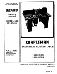
1
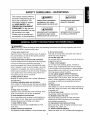
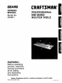
SF./_S
CRAFTSMANo
OWNERS
MANUAL
Model No.
26462_0
PROFESSIONAL
MID-SIZED
ROUTER TABLE
WARNING:
Before operating
product, read this
manual and follow
all its Safety
and Operating
Instructions.
Sears, Roebuck
26462
12/00
Printed in U.S.A.
and Co., Hoffman
Estates IL 60179 USA
4 9LCN-
84
General Safety Instructions for Power Tools ................................................
3
Additional Safety Instructions for Router Tables ......................................... 4
Introduction ........................................ ..........................................................
Optional
Unpacking
Assembly
Router Table Accessories
and Checking
== = • == • • • • =m • =l
...............................................................
5
Contents ...............................................................
5
• • • • • • • • • • • • • m • • • • • • • • • • • • • • • • • • • =,
• • • • • • •=
•m == • • • • • • • • • • =•==
• •l
• • • = • • =l
• =• • 1===
• == • =•=
• • =6
Tools Required ........................................................................................................................
6
Router Table .............................................................................................................................
6
Mounting Router to the Router Table ....................................................................................
7
Fence Assembly ......................................................................................................................
8
Attachment of the Fence Assembly to the Router Table ....................................................
8
Attachment
9
of the Overhead Guard to the Fence Assembly ..............................................
Push Block Assembly ............................................................................................................
Operation
'...5
9
Push Block Assembly to the Router Table Fence .............................................................
10
Miter Gauge Assembly .........................................................................................................
10
Dust Collecting Attachment .................................................................................................
10
Mounting Router Table to a Workbench or Work Surface ................................................
Alternate Method ...................................................................................................................
10
11
Selecting and Installing the Router Table Inserts ..............................................................
11
.................................................................................
• •
.....•.... ..........
12
General ...................................................................................................................................
12
Electrical Requirements / Switch Box Operation ..............................................................
Router and Switch Box Operations ....................................................................................
12
13
Using the Router Table .........................................................................................................
14
Alignment of Unitized Fence to Miter Bar Slot ..................................................................
14
Adjusting Depth and Height of Cut .....................................................................................
Routing Using Fence without the Push Block ...................................................................
14
14
Using Router Table as a Jointer (Full Edge Cutting) ......................................................
14
Edge Cutting with Non-Piloted
15
Router Bits ....................................................................
Edge Cutting with Piloted Router Bits ............................................................................
15
Grooving, Fluting, and Veining .......................................................................................
16
End Cutting
Routing
using the Fence with the Push Block ...........................................................
using the Miter Gauge ...........................................................................................
Parts List ..............................................................................................................
2
16
18
19
SAFETY GUIDELINESThis manual
contains
informa-
tion that is important for you to
know and understand. This
information relates to protecting YOUR SAFETY and
PREVENTING
EQUIPMENT
PROBLEMS.
To help you recognize this information,
we use
the symbols to the right.
Please read the manual and
pay attention
to these sections.
DEFINITIONS
I CAUT'ONI
IADANGER l
URGENT SAFETY INFORMATION
A HAZARDTHAT
INFORMATION
-
FOR PREVENTING
DAMAGE TO EQUIPMENT
WILL CAUSE
SERIOUS INJURY OR LOSS OF LIFE
I_WARNING]
IMPORTANT
SAFETY INFORMATION
A HAZARD THAT MIGHTCAUSE
SERIOUS
I
-
NOTE
I
INFORMATION THAT YOU SHOULD
PAY SPECIAL ATTENTION TO
INJURY OR LOSS OF LIFE
I _,WARNING
Failure to heed all safety and operating instructions and warnings regarding use of this
product can result in serious bodily injury.
1. Know your power tool
Read the owner's manual carefully. Learn its application and limitations as well as the specific potential
hazards peculiar to this tool.
2. Ground all tools (unless double insulated)
If tool is equipped with an approved three-conductor
cord and a three-prong grounding type plug, it
should be plugged into a three hole electrical receptacle. If adapter is used to accommodate a two-hole
receptacle, the adapter wire must be attached to a
known ground (usually the screw securing receptacle
cover plate). Never remove third prong. Never connect green ground wire to a terminal.
3. Keep guards in place
Maintain in working order, and in proper adjustment
and alignment.
4. Remove adjusting keys and wrenches
Form a habit of checking to see that keys and adjusting wrenches are removed from tool before turning it
ON.
5. Keep work area clean
Cluttered areas and benches invite accidents. Floor
must not be slippery due to wax or sawdust.
6. Avoid dangerous environment
Do not use power tools in damp or wet locations or
expose them to rain. Keep work area well lighted.
Provide adequate surrounding work space.
7. Keep children away
All visitors should be kept a safe distance from
work area.
8. Make workshop child-proof
Use padlocks, master switches, or remove starter keys.
9. Do not force tools
They will do the job better and safer at the rate for
which they were designed.
10. Use the right tool
Do not force tool or attachment to do a job it was not
designed to perform.
11. Wear correct apparel
Do not wear loose clothing, gloves, neckties or
jewelry (rings, wristwatches) that may get caught
in moving parts. Non-slip footwear is recommended.
Wear protective hair covering to contain long hair.
Roll long sleeves above the elbow.
12. Use safety goggles (Head Protection)
Wear safety goggles (must comply with ANSI
Standard Z87.1) at all times. Also, use face or dust
mask, if cutting operation is dusty, and ear protectors (plugs or muffs) during extended periods of
operation.
13. Secure work
Use clamps or a vise to hold work when practical. It's
safer than using your hands, and it frees both hands
to operate tool.
14. Do not over reach
Keep proper footing and balance at all times.
15. Maintain tools with care
Keep tools sharp and clean for best and safest
performance. Follow instructions for lubricating
and changing accessories.
16. Disconnect tools before servicing
Before servicing, when changing accessories such
as blades, bits, cutters, etc.
17. Avoid accidental starting
Make sure switch is in OFF position before plugging in.
18. Use recommended accessories
Consult the owner's manual for recommended
accessories and follow the instructions. The use of
improper accessories may cause hazards.
19. Never stand on tool
Serious injury could occur if the tool is tipped or if
the cutting tool is accidentally contacted. DO NOT
store materials above or near the tool making it necessary to stand on the tool to reach them.
20. Check damaged parts
Before further use of the tool, any guard or other
part that is damaged should be carefully checked to
ensure that it will operate properly and perform its
intended function. Check for alignment of moving
parts, binding of moving parts, breakage of parts,
mounting, and any other conditions that may affect
its operation. A guard or any other part that is
damaged should be properly repaired or
replaced.21. Direction of feed
Feed work into a blade or cutter AGAINST the
direction of rotation of the blade or cutter only.
22. Never leave tool running unattended
Turn power OFF. DO NOT leave tool until it comes to
a complete stop.
23. Keep hands away from cutting area
24. Store idle tools
When not in use, tools should be stored in dry, high
or locked-up place - out of reach of children.
25. Do not abuse cord
Keep cord away from heat, oil and sharp edges.
26. Outdoor extension cords
When tool is used outdoors, use only extension
cords suitable for use outdoors and so marked.
27. Never use in an explosive atmosphere
Normal sparking of the motor could ignite fumes,
flammable liquids, or combustible items.
28. Drugs, alcohol, medication
DO NOT operate tool while under the influence of
drugs, alcohol, or any medication.
1. Always wear eye protection that complies with ANSI
Standard Z87.1.
2. Noise levels vary widely with location. To avoid possible hearing damage, wear ear plugs or ear muffs
when using your router table for long periods of time.
3. For dusty operations, wear a dust mask along
with safety goggles.
4. Follow the instructions in your router owner's manual.
12. Keep hands clear of the router bits and working
area.
13. Make and use a push stick to move small
workpieces across the cutting area.
14. Clean the router after use. The use of a wet/dry vac
or vacuum equipment is recommended.
15. Always make sure that work surface of the router
table is clean and free from dust, chips, and foreign
particles that can interfere with the cut you are
going to make. The use of a wet/dry vac or vacuum
equipment is recommended.
16. Check the function of the guard before each use.
Remove all dust, chips, and any other foreign particles that can affect its function.
5.L_'WARNINGJ
Vibrations, caused by the router
during use, can cause fasteners to become loose.
Before use and periodically during use, check all
fasteners to make sure that all are tight and secure.
6. Do not use this product until all assembly and installation steps have been completed. Make sure you have
read and understood all safety and
operational instructions in this manual and the
router owner's manual.
7. Make sure that the router bit is properly positioned
and clamped in the router before making any cuts.
8. Do not use the router table as a workbench or work
surface. Doing so may damage it, causing it
to be unsafe to use. A workbench should be used
for this purpose.
9. This product is designed for cutting flat workpieces.
Do not cut or attempt to cut workpieces that are not
flat.
10. This product is designed for cutting wood
workpieces only. Do not use to cut metal or other nonwood materials.
11. The use of auxiliary in-feed and out-feed
supports is strongly recommended when routing long
workpieces. Otherwise those workpieces can cause
the router table to tip over.
Read and Understand this instruction book
completely BEFORE using this product.
17. '_WARNINGI
Never put your fingers under the
overhead guard when the router is plugged into an
electrical outlet or when the router bit is rotating.
18. Always use the fence to guide the workpiece.
19. Always feed the workpiece AGAINST the rotation
of the cutter or router bit.
20. Router bits are extremely sharp; be extra careful
when handling and using them.
21. Make sure that the router bits being used are sharp
or have been properly resharpened. This will permit
fast, efficient, and SAFE routing.
22. Some routers, when positioned in an upside down
position (such as on a router table), will drop
or fall out of the router base when the base clamp is
loosened to adjust height or depth of cut. Therefore, it
is extremely important to support the router from
below when making these adjustments or whenever
the base clamp is loosened.
23. Always look under the router table at the router
switchboxwhenturningthe routerONor OFF.DO
NOTtouchanythingbuttheswitchboxwhendoing
this.NEVERreachundertheroutertableforanyreasonwhentherouteris running,exceptto turnit OFF.
24.[ A WARNING
I
26. If ANY of the parts is missing, DO NOT attempt
to assemble, install, or use your router table until the
missing parts have been found or replaced and your
router table has been properly and correctly assembled per this manual.
I
J Before making any cut, make
sure the router is turned OFF, the router bit is not
rotating, and the power cord is unplugged from the
electrical outlet. Then, make absolutely sure that the
overhead guard clears the router bit and the workpiece. A trial pass, with the router turned OFF and the
router bit not turning, is strongly recommended.
25.l _WARNINGJ
/
I
27.[ _L, DANGER JNever use the floor stand as a
ladder and DO NOT stand on the router table.
Never leave the router table
unattended while the router is running. Turn the router
OFF before leaving the router table for any reason.
Your Craftsman Router Table comes with the following:
• A unique 4" high unitized fence with fence guides that
provide parallel movement.
• Rulers molded into the table top that provide fast
and accurate fence adjustment for making the
following items:
- Tenons
- Sliding dovetail joints
- Tongue & groove joints
- Face cuts
• The unique fence also allows you to perform these
additional routing operations:
-
Veining
Fluting
Making crown molding
Making cuts up to 2-1/2" from the edge of the
workpiece toward the center of the workpiece
• A specially designed push block with a quick clamp
that can clamp work pieces up to 4" wide, for end grain
or edge routing.
• An accurate jointing fence that is quickly adjustable to
the proper depth of cut.
• A dust collector port on the fence to which most 2-1/2"
wet/dry vac hoses can be attached.
9-26478 Craftsman Router Table Floor Stand,
places router table at a convenient working height,
has adjustable floor levelers, and two steel shelves
for storage.
9-25468 Craftsman Guide Master RouterTable Push
Shoe, aids in push shoe and hold down operations,
accurate measurement and router table set-up,
transforms into a miter gauge, and gives quick set-up
for 1/2" sliding dovetail joints.
9-25333 Craftsman Industrial Router Adapter Plate,
for mounting non-Craftsman 1/4" and 1/2" reuters to
the router table. The holes for mounting the router
must be located and drilled by the user. The fasteners
for mounting the router to the adapter plate are not
included and must be obtained separately.
9-26478 Craftsman Router Table Floor Stand,
places router table at a convenient working height,
has adjustable floor levelers, and two steel shelves
for storage.
Refer to Parts List on page 19.
• /AI[jIAWARNINGj
• In order to simplify handling and to minimize any
damage that may occur during shipping, your router
table comes unassembled.
• Separate all parts from the packaging materials and
check each part against the illustrations and
the parts list at the end of this manual, to make
sure that all parts have been included. Do this before
discarding any of the packaging material.
If ANY of the parts is missing,
DO NOT attempt to assemble, install, or use your
router table until the missing parts have been
found or replaced, and your router table has been
properly and correctly assembled per this manual.
• Contact your local Sears Retail Outlet for missing or
replacement parts.
5
FIGURE 2 - Front Corner of Router Table and Leg
TOOLS REQUIRED
• Phillips screwdriver.
° Small or medium sized adjustable wrench
(or a set of nutdrivers).
° Electrical with 5/32" drill bit.
• Hammer
10-32 Hex "Keps"
Router _
Table Leg _/
Cut Away_\
\\\\
"
ical)
_///fY
7/I'7"
ROUTER TABLE
View_
Second V-Slot-_'_;_._
to be used for
_
_k_Y-.
/v
-_
///
_ik_/'/
J
/
Spacer
.10-32
7
"_
x 1-3/4"
Long
Truss
Head
Machine
Screw
(Typical)
securing Leg
_'
#10-32 x 5/8" Long Truss /
Head Machine Screw
(Typical)
I
NOTE
FIGURE 3 - Back Corner of Router Table and Leg
Cut Away
View
I Legs are positioned to the back
edge of the router table, as shown in Figures 1 and 3.
#10-32 x 5/8'
Long Truss
Head
Machine
Screw,
4 places
(Typical)
Table
Leg
3. Position the leg spacers, two per leg, as shown in
Figure 2. Spacers MUST be positioned at the two
holes in the front of the router table, as shown in
Figure 2. Note that only the second V-slot will be used
to secure the leg from the side in the front of the table,
also noted in Figure 2.
4. Secure each table leg using five (5) #10-32 x 5/8"
long truss head machine screws, two (2) #10-32 x
1-3/4" long truss head machine screws and seven (7)
#10-32 hex "KEPS" nuts. See Figure 3 for a detail of
how the leg is secured to the back area of the table.
5. Repeat steps 3 and 4 for the other leg.
6. SECURELY TIGHTEN all fasteners at this time.
Router
Table
#10-32 Hex
"Keps" Nut,
,
4 places
(Typical)
7. Position the switch box (Part No. 29LCN-1019)
against the front of the router table as shown in
Figures 4 and 5. Secure the switch box to the router
table using two (2) #10-32 x 5/8" long truss head
machine screws and two (2) #10-32 hex "KEPS" nuts.
FIGURE 1
I
I
I
Head Machine Screw\
/#10-32
Router_
(Typical' 5 places)k_
Table
•e,
_--_'_//
\
\
k_'
/ ///_
_
/
Hex
I There are two hex shaped recesses
in the switch box assembly case, into which the hex
"KEPS" nuts fit. They should be inserted into the recess
with the washer side of the nut facing outward.
r.eps"
Nut (Typmal)
_'/
NOTE
FIGURE 4
/_
#10-32 Hex t
'Keps" Nut, _
(Typical)/_
I
-32xl_
#10-32 x 5/8" LongTruss\
H/
l/ _,
k_
,,.
#1°LongT-uss .; " _
Head
Mac_F"
_crew
(=yp=cai)
_
\ Leg Spacer
.
_
Front of
-
'_ _
(Typmal, 4 places)
_
RouterTable
Front of Router Table
6
/
_--....___
/
Leg
l
B
1. Position the router table top (Part No. 29LCN-981)
as shown in Figure 1, with the bottom of the table top
facing toward you.
2. Position the table legs (Part No. 29LCN-1283)
relative to the router table top as shown in Figure 1.
Note that the legs are positioned to the inside of the
table top sides.
]
_ #10-32
Switch
x 5/8" Long
Truss Head
Machine
Screw
FIGURE 5
#10-32
FIGURE 7
Hex "Keps"_
Nut, (Typical)_
-_,_,_
_
Switch_
_
_ --///_
_
/
\\/
,_/
/
Router
_
#10-32 x 518" Long
Leg
i
i
Table
'_
_
_
Y
'_
i
!
'_
Flat Countersunk
Head Machine
Screw
w/Phillips Recess
"_
Front of--.
Router
Table
#10-32 Head
518"Machin
Long
Truss
Screw, (Typical)
MOUNTING
2. Store the screws and the base plate in a convenient
location.
ROUTER TO THE ROUTER TABLE
I WARNINGI ALWAYS
UNPLUG
ROUTER
3. While holding the router upside down, position the
router against the bottom of the router table as shown
in Figure 8. Rotate the router until the three threaded
holes in the router base line up with the three corresponding countersunk holes in the top of the router
table. The holes will line up in ONE position only.
(The router handles should be oriented as shown in
Figure 8.)
4. Insert three 5/16-18 x 1-1/4" long flat countersunk
head machine screws through the three holes in the
table top, as shown in Figure 9, and thread them into
the threaded holes in the router base housing.
5. TIGHTEN the screws SECURELY to the router.
BEFORE MOUNTING.
Craftsman Routers with Three-Hole and 6"
Diameter Base Plates
1. Remove the router base plate (back plate) from the
router.
2. Store the screws and the base plate in a convenient
location.
3. While holding the router upside down, position the
router against the bottom of the router table as shown
in Figure 6. Rotate the router until the three threaded
holes in the router base line up with the three corresponding countersunk holes in the top of the router
table. (The router handles should be oriented as shown
in Figure 6.)
FIGURE 8
i
FIGURE 6
FIGURE 9
4. Insert three #10-32 x 5/8" long flat countersunk head
machine screws through the three holes in the table
top, as shown in Figure 7, and thread them into the
threaded holes in the router base housing.
5. TIGHTEN the screws SECURELY to the router.
i
',
Craftsman Router Models 9-27500, 9-27510,
and 9-27511
1. Remove the router base plate (back plate) from the
router.
7
x 1-1/4" Long
Flat Countersunk
Head
Machine Screw
w/Phillips Recess
Other Brands of Routers
It will be necessary for you to purchase a Craftsman
Professional Router Adapter Plate, #25333, from your
local Sears Retail Outlet, or through the Sears
Catalogue.
Routers with a total overall height of 13 inches or less,
and a base diameter of 7 inches or less can be
accommodated.
m
3. Push the adjustable jointing fence into the router
table fence as far as it will go and tighten the clamping
knob.
4. Assemble the fence guide to the bottom of the fence
using two #10-32 x 7/8" long panhead machine screws
and two #10-32 hex "KEPS" nuts, as shown in Figure
12. (The nut portion of the hex "KEPS" nut fits into the
hex recess, with the washer portion facing out of the
recess.)
i
I
NOTE
I Because of vibration that occurs
FIGURE 12
during routing, occasionally check the screws to
assure that they have not become loose.
#10-32 x 7/8" Long
Panhead Machine Screw
"_
!
FENCE ASSEMBLY
1. Slide the adjustable jointing fence (Part No. 291.-758)
into the pocket on the router table fence (Part No. 29L994), as shown in Figure 10. The V-guide on the
adjustable jointing fence will mate with and slide on the
V-guide in the router table fence.
NOTE: Orientation of Front
in Fence must be toward the Front
of the RouterTable Fence
FIGURE 10
Surface of
Fence Guide must
be flush with Back
Surface of Router
Table Fence
Fence Guide
#10-32 Hex "KEPS" Nut-__
(Typical)
Router
Table
Fence
ATTACHMENT OF THE FENCE ASSEMBLY TO
THE ROUTER TABLE
I _'WARNINGI
Always unplug router before
attaching or removing fence from table,
Adjustable
Jointing
Fence
1. Position the fence on router table as shown in
Figure 13.
FIGURE 13
I
2. Insert a 1/4"-20 x 1" long hex head bolt through the
hole with a hex recess in the router table fence, and
through the slot in the adjustable jointing fence as
shown in Figure 11. While holding the head of the bolt
in the hex recess, place a 9/32" I.D. x 3/4" O.D. x 1/16"
thick washer over the bolt, and thread the adjustable
jointing fence clamping knob (Part No. 29L-659) onto
the bolt.
Jointing
Fence_
Clamping
Knob_
9132" I.D. x 314" O.D. __
x 1/16" Thick Washer
_
1/4-20 x 1" Long
Finished Hex Head Bolt
Fence Clamping
1_"_
_3_
'__
i
!,
-'._77k
_--_/
(Typical) __
-'
1-3/4" Long
Rex Head
Bol_i/_
FIGURE 11
Adjustable
_
9/32" I.D. x _
3/4" O.D. _
x 1/16"
/
Thick
_
Washer
__t_',
ft_
Y I,!
/ i _'_"_\
I !_
(Typ,ca,)
_,."_
_
Knob (Typical)
I/
I
I!
!
_;
/V,-',%_
_<--_'_,
,:.s_'_. _
2. Insert a 1/4"-20 x 1-3/4" long round head square
neck bolt, from underneath the table, though the slot in
the recess, as shown in Figure 15, and through the slot
in the fence as shown in Figures 13 and 14.
3. While holding the head of the bolt in the recess,
place a 9/32" I.D. x 3/4" O.D. x 1/16" thick washer over
the bolt, and thread the fence clamping knob (Part No.
29L-659) onto the bolt to loosely secure the fence as
shown in Figures 13 and 14.
Adjustable
Jointing
Fence
8
FIGURE 16
4. Repeat steps 1 through 3 for the other side of
the fence.
Overhead
5. Make sure the adjustable jointing fence is inside the
router table fence as far as it will go and that the
clamping knob has been securely tightened.
_
Guard\
_/
PivotPin
_
_//
_///._
/!///'"_
Overhead
Guard
_'d t__
FIGURE 14
/
Fence
Clamping
Knob
L_
/,j
-_-_-L
/\
/
\
/
\
_
9/32" LD. x
3/4" O.D.
x 1/16"
Thick
Washer
0"ypical)
/_
/) _'_=_
'_
_
_
Fence
J__WARNINGJ
Guide
t
114-20 x
It_l
\
I'I i[_
1-3/4",ong II
Round Head
Square IL
Neck Bolt
\ :
_\ _
.//
J
I
//
"" Channel
[
Once the overhead guard has
been assembled to the fence, DO NOT remove it
for any reason. Its removal can result in an unsafe
operating condition that can result in possible
bodily injury.
Rn°uter
_./|l
Table
PUSH BLOCK ASSEMBLY
FIGURE 15
_
Fence Clamping Knob
9/32" I.D. x 314" O.D. x 1116"
Thick Washer (Typical)
(_YI_
L
_---'_/_/'_
_ _-_///_
_'_[
i
( /
ocket for
Bolt Head
tores,,n
i
Z
"_l/
_/
1/4-20
x 1-3/4" /
/
!
t
ATTACHMENT OF THE OVERHEAD
THE FENCE ASSEMBLY
1. Thread the small end of the clamp rod into the
threaded hole of the clamp plate, until the rod bottoms
out securely against the plate.
2. MAKE SURE THAT THE CLAMP PLATE IS ORIENTED SO THAT THE "C" ON THE CLAMP PLATE
FACES OUTWARD.
3. Assemble the1/4" I.D. x 1/2" O.D. x 3/64" thick spring
lock washer and 1/4-28 hex nut to the clamp rod.
4. SECURELY TIGHTEN THE NUT ON THE CLAMP
ROD.
5. Insert the other end of the clamp rod through the
hole in the push block. MAKE SURE THE ORIENTATION OF THE PUSH BLOCK tS AS SHOWN IN FIGURE 17.
6. Assemble the 11/32" I.D. x 11/16" O.D. x 1/16" thick
washer and the 5/16-18 wing nut to the clamp rod.
7. It is not necessary to tighten the wing nut. The
clamp rod should rotate freely in the clamp block.
Long Round Head
Square Neck Bolt
GUARD TO
1. Assemble the overhead guard to the router table
fence using two 1/4" pushnuts and the overhead guard
pivot pin, as shown in Figure 16.
2. Prior to inserting the overhead guard pivot pin, press
one of the pushnuts onto one end of the pivot pin. (It
may be necessary to tap the pushnut onto the overhead guard pivot pin with a hammer while supporting
the other end of the overhead guard pivot pin.)
3. Position the overhead guard on the fence so the
holes in the guard line up with the through-hole in the
router table fence. Make sure the orientation of the
overhead guard is as shown in Figure 16.
4. Insert the pivot pin through the aligning holes.
5. Press the second pushnut onto the other end of the
overhead guard pivot pin.
6. Move the guard up and down a few times to ensure
that it moves freely.
FIGURE 17
5116-18 Wing
11/32"
I.D. x 11/16"
O.D. x 1/16" Thick
Threaded
Small
End
shoulder
Block
Rod
114"\
Helical\
Lock_
Washer
_
_'_-
"_"_
"C" on Clamp Plate
_ //_
Clamp Plate
1/4-28_8Hex Nut
I _'WARNINGI
I
The vibrations from operating the
NOTE
I There are two round holes in the
router can, from time to time, cause the hex nut
and the clamp plate to become loose on the clamp
rod. PERIODICALLY CHECK THESE FASTENERS
miter bar. Make sure the #10-32 x 1/2" long truss
head machine screw enters the hole shown in
Figure 19.
AND ALL FASTENERS to ensure that they are tight
and secure.
1. Tighten the screw so that it touches the miter bar
but still provides a resistance to rotating the protractor
head.
PUSH BLOCK ASSEMBLY TO THE ROUTER
TABLE FENCE
2. Assemble the knob (Part No. 31 L-560), the
13/64" I.D. x 9/16" O.D. x .040" thick washer and the
#10-24 x 3/4" long round head square neck bolt to the
miter gauge, as shown in Figure 20.
1. Position the clamp plate relative to the push block,
as shown in Figure 18.
2. Align the rib on the push block with the groove in the
front face of the fence.
FIGURE 20
3. Assemble the push block to the fence as shown in
Figure 18. The push block should move freely along
the full length of the fence.
----_
FIGURE 18
Miter Bar_
#10-24 xHead
3/4" Long
Round
_quare
Neck Bolt
Push
Claml
Fence
113164"
I.D. x
9/16" O.D. x
.040" Thick
Washer
ProtractOrHead
__(_
Plate
Knob
DUST COLLECTING
ATTACHMENT
The router table fence is equipped with a port at the
back for the attachment of the hose from a wet/dry vac
The port will accommodate a 2-1/2" diameter hose
nozzle.
MITER GAUGE ASSEMBLY
To attach, push the nozzle into the port while holding
the fence in place.
Assemble the protractor head (Part No. 29L-293) to
the miter bar (Part No. 29LCN-1119), as shown in
Figure 19, using a #10-32 x 1/2" long truss head
machine screw. The screw will self thread into the hole
in the protractor head.
_CAUTIONI
the use of a wet/dry vac may result in an excessive collection of saw dust and chips under the fence assembly
and the overhead guard. This can hinder the performance of the router table and the fence assembly.
FIGURE 19
_-y--------
10-32 x 1/2" Long Truss
'_
Head Machine
,
/
/
\
Operating the router table without
Screw
I_WARNINGI
Use this hole
When doing the above, keep
the following in mind:
• The router table must be turned OFF.
Miter Bar _
Protractor
""
•The router bit must not be turning.
• The router power cord must be unplugged from
the outlet.
_,,
MOUNTING ROUTER TABLE TO A WORKBENCH
OR WORK SURFACE
Head
I_WARNING
The router table must always
be FIRMLY and SECURELY mounted to a work
10
surface before use. Failure to do so could cause
the router table to tip over or slide, resulting in
property damage and/or serious personal injury.
8. TIGHTEN the screws SECURELY.
9. Place the router table on a workbench or other stable and sturdy surface, and firmly secure the board
with screws or other suitable means.
1. Set the router table on a workbench or other stable
and sturdy surface.
2, While holding the router table in place, spot the location of the two mounting holes in each of the legs onto
the workbench. (Total number of holes is four)
3. Remove the router table from the workbench and
set it aside.
m
I
I
NOTE
I The specially designed legs with
foot boss may be clamped to a workbench or work
surface. Always make sure the clamps are tight
before and after using the router.
SELECTING AND INSTALLING THE ROUTER
TABLE INSERTS
FIGURE 21
This router table comes with three tabletop inserts in
the following hole sizes:
• 1-1/4" diameter, for use with router bits with diameters up to 1-1/8"
• 1-7/8" diameter, for use with router bits with diameters up to 1-3/4"
• 2-1/8" diameter, for use with router bits with diameters up to 2"
• For router bits with diameters between 2" and 2-3/4",
do not use a table top insert.
Router
Table
Leg
I _'WARNINGI
Mounting
Holes/
Foot Boss
A 2-3/4" Diameter router bit is
the LARGEST router bit that can be used on this
router table.
Work Surface/Table
6. Secure the router table to the workbench using the
four #12 x 1-3/4" long round head wood screws (not provided). Applying a little soap to the screw threads will
make it easier to thread the screws into the drilled holes.
7. TIGHTEN the screws SECURELY.
1. Select the tabletop insert that accommodates the
router bit to be used.
2. Assemble the insert to the tabletop by pressing it
into the large hole in the top of the router table, as
shown in Figure 22.
3. Press down equally over the tabs on the insert, so
that the tabs snap into place.
4. To remove, insert a finger in the insert hole and gently pull up until the tabs disengage the hole. When not
in use, store the inserts in a convenient place.
ALTERNATE METHOD
I _WARNINGI
1. Cut a board 18-1/4" wide by 24" long from a piece of
3/4" thick wood.
2, Place the router table on the board so that the spacing from the edge of the board to the router table legs
is equal on all four sides of the board.
3. While holding the router table in place, spot the location of the two mounting holes in each of the legs onto
the board. (Total number of holes is four)
4. Remove the router table from the board and set it
aside.
5. Drill a 5/32" diameter hole at each of the spotted
hole locations.
6. Position the router table on the board so that the holes
in the legs line up with the drilled holes in the board.
7. Secure the router table to the board using four #12 x
1-3/4" long round head wood screws (not provided).
Applying a little soap to the screw threads will make it
easier to thread the screws into the drilled holes.
top inserts from the tabletop unless the router bit
has been removed from the router, and the router
is unplugged.
4. Drill a 5/32" diameter hole at each of the spotted
hole locations.
5. Position the router table on the workbench so that
the holes in the legs line up with the drilled holes in the
workbench.
DO NOT attempt to remove table
FIGURE 22
Router Table,
Fence_
11
/,
_, --
,\
,
GENERAL
If a properly grounded outlet is not available, a temporary adapter, as illustrated in FIGURE B, may be
used to connect this plug to a two-hole receptacle, as
shown in FIGURE C.
The power switch box is designed to be used with
most Craftsman router tables. It provides the convenience of an "ON-OFF" switch box at the front
of the table, thus eliminating the need to reach
underneath the table to turn the router "ON" and
"OFF".
The power switch box also provides an optional
simultaneous "ON-OFF" control of an additional
FIGURE A
Cover of
Grounded
accessory, such as a light, vacuum, etc. The switch
box incorporates an internal, resettable circuit
breaker to provide protection in overload situations.
Adapter
FIGURE C
Cover of
Grounded
Outlet Box
Outlet Box_
_
ELECTRICAL
FIGURE B
Grounding
Grounding
Pin
Means
REQUIREMENTS
In the event of a malfunction or breakdown, grounding provides the path of least resistance for electric
current in order to reduce the risk of electric shock.
The temporary adapter should be used only until a
properly grounded outlet can be installed by a
qualified electrician. The green colored rigid ear or
lug extending from the adapter must be connected to
a permanent ground, such as a properly grounded
outlet box.
This switch box is equipped with an electric cord
that has an equipment grounding connector and a
grounding plug. The plug must be plugged into a
matching outlet that is properly installed and grounded in accordance with all local codes and ordinances.
DO NOT modify the plug provided if it will not fit the
outlet. Have the proper outlet installed by a qualified
electrician.
I_WARNING]
Do not permit fingers to touch
terminals of the plug when installing or removing
from the outlet. If not properly grounded, this power
tool can present the potential hazard of electrical
shock, which can possibly result in death, particularly
when used in a damp location, in proximity to plumbing or out of doors. If an electrical shock occurs, there
is always the potential of a secondary hazard, such
as your hands contacting the router bit.
Improper connection of the equipment grounding
conductor can result in risk of an electric shock. The
conductor with insulation that has a green outer surface, with or without yellow stripes, is the equipment
grounding conductor. If repair or replacement of the
electric cord or plug is necessary, DO NOT connect
the equipment grounding conductor to a live terminal.
Check with a qualified electrician or service person
if the grounding instructions are not completely
understood, or if there is doubt as to whether the
switch box is properly grounded.
I,_WARNING
Use the switch box only when
properly assembled to the router table. Use only with
a router which has also been properly installed on a
properly assembled router table.
Use only 14 gauge, or larger, three-wire extension
cords that have three-prong grounding plugs and
three-hole receptacles that accept the tool's plug.
SWITCH BOX OPERATION
Repair or replace a damaged or worn cord
immediately.
This section explains the operation and features of
the switch box prior to plugging the power cord into
an electrical outlet. The intent is to familiarize the
The electrical outlet on the back of the switch box
user with the switch box operation without actually
turning on the router.
will accept either a two-prong plug from a DOUBLE
INSULATED router or accessory, or a three-prong
grounding type plug.
This switch box is intended for use on a circuit that
has an outlet, as illustrated in FIGURE A. The switch
box has a grounding plug, as illustrated in FIGURE A.
12
ROUTER AND SWITCH BOX OPERATIONS
The switch box incorporates two positive features to
prevent inadvertent switching on of the router and the
unauthorized, and possibly hazardous, use by others.
Inadvertent switching on of the router is prevented by
the clear plastic switch box cover. The cover must be
raised and the switch box manually toggled to the "ON"
position to start the router. Also, the safety key can
be removed to disable the switch box by "locking" the
switch box in the "OFF" position, thus preventing
unauthorized and possible hazardous use.
This section explains operation of the switch box with
the power cord plugged into an electrical outlet.
The router will turn "ON" when the switch box is
toggled to the "ON" (or "RESET") position.
1. Position the "ON-OFF" switch on the router in the
"ON" position. On certain routers this will require the
use of the switch trigger and "Lock-On" button. (Consult
router owner's manual.) Make sure the switch box
lever is in the "OFF" position when doing this.
2. To turn the router "ON", slide finger under the
switch box cover and toggle the switch box to the
"ON" position, as described in the previous section.
3. To turn the router "OFF", press the switch box cover,
as described in the previous section.
The switch box can be turned "OFF" by pressing the
switch box cover with the hand.
FIGURE 23
o
]
I
NOTE
I In the event of an overload situa-
tion, the internal switch box circuit breaker may trip
and toggle the switch box to the "OFF" position. This
will interrupt the power to the router and/or vacuum.
If this occurs please do the following:
/
1. Unplug the switch box cord from the electrical outlet.
2. Clear the workpiece from the router table.
3. Correct the cause of the overload situation
(i.e., the removal of too much stock or use of too high
a feed rate).
Switch Box /
S
4. Plug the switch box power cord into the electrical
outlet.
To operate the switch box, proceed as follows:
t
NOTE
II
5. Restart the router as described in the section,
Router and Switch Box Operations.
Because the switch box also
functions as a circuit breaker, the "ON" position is
labeled RESET on the switch box. For clarity this
instruction uses "ON" in place of RESET.
P
I
[_tLWARNING]
SAFETY OF OTHERS, do the following when the
router table is not in use:
1. Insert the safety key into switch box.
See FIGURE 23.
2. To turn router "ON", insert finger under switch box
cover and toggle switch box to "ON" position.
3. To turn router to "OFF", press switch box cover.
NEVER leave router UNATTENDED until it has come
to A COMPLETE STOP.
4. To lock switch box to "OFF" position, remove safety
key from switch box.
1. Toggle the switch box lever to the "OFF" position
and remove the safety key.
2. Turn the router off.
3. Unplug the switch box power cord from the
electrical outlet.
4. Remove the router bit from the router.
5. Make sure the router collet assembly is below
the top of the router table.
6. Store the switch box safety key in a safe
location where it is not available to children or
other unauthorized persons.
With the safety key removed from the switch box, the
switch box cannot be toggled to the "ON" position.
t
I
NOTE
For your own SAFETY and the
I 9-26462 Replacement safety keys
J
I WARNINGI
In the event of a power failure,
blown fuse, or the router "stalling out" while
routing:
=Turn the router OFF by pushing on the clear
cover on the switch box.
are available at your local Sear Retail Store.
I ,_wARNING]
Before proceeding any further,
make sure the switch on the router is in the"OFF"
position and the switch box lever is in the "OFF"
position.
- Remove the safety key from the switch box.
• UNPLUG the switch box cord from the electrical
outlet until the problem has been corrected.
The switch box power cord can now be plugged into
an extension cord.
13
"IGURE 25
USING THE ROUTER TABLE
The fence on your router table is provided as a guide
to hold the work piece for accuracy in routing.
Line "B"
Scrap
Wood
I_I_WARNING]
BEFORE each and every use,
make sure the router table is SECURE on a workbench and DOES NOT MOVE.
ALIGNMENT
SLOT
OF UNITIZED FENCE TO MITER BAR
1. Line up the front of the fence with the "0" marks on
the top of the router table, as shown in Figure 24.
Router Bit
FIGURE 24
Fence \
Clamping \
Clamping
bit is aligned with line "B". (Refer to your router owner's
AFTER MAKING THIS ADJUSTMENT, BE SURE
ROUTER IS SECURELY TIGHTENED IN THE
ROUTER
THErouter
BIT IS
SECURELY
4.
Raise orBASE,
lower the
until
top cuttingTIGHTedge of the
manual
forTHE
adjusting
your CHUCK
router properly.)
ENED IN
ROUTER
AND THE ROUTER
BASE IS SECURED TIGHTLY TO THE ROUTER
_Fence
5. Remove the board from the fence and LOWER THE
TABLE TOR
OVERHEAD GUARD TO OPERATING POSITION.
"O" M_
on Ruler
'°OnRMu_rk
"'_
I
I
NOTE
I YOUshou!d substitute a scrap board
for the actual workpiece while making adjustments.
2. Tighten both fence clamping knobs MAKING SURE
THAT THE FENCE ASSEMBLY DOES NOT MOVE.
ADJUSTING
NOTE
I '_WARNINGI
DO NOT OPERATE ROUTER IF
ANY PART OF THE BIT CONTACTS THE GUARD.
DEPTH AND HEIGHT OF CUT
I
I The router fence should be parallel
ROUTING USING FENCE WlTHOUTTHE
BLOCK
or nearly parallel to the miter bar slot. Refer to previous section on ALIGNMENT OF UNITIZED FENCE
TO MITER BAR SLOT.
PUSH
Using Fence as a Jointer (Full Edge Cutting)
For maximum strength and accuracy, boards to be
joined together should be smooth and true. The edges
should be true to the work piece surface. You can true
the edges on your router table using a straight bit.
UNPLUG the router for these adjustments. Rotate the
overhead guard upward in order to have full access to
the router bit for making adjustments. Select a board
that is smooth with edges true to each other and its
surfaces. Other recommendations are the following:
1. Mark lines "A" and "B" on the end of this board. Line
1. Check to see if the face of the adjustable jointing
fence is flush with the face of the router table fence.
If not, loosen the jointing fence clamping knob on the
jointing fence and push jointing fence in until it is flush
with the router table fence. Tighten the knob on the
jointing fence.
m
"A" indicates the desired depth of cut (amount of material you want to remove) and line "B" indicates the
desired cutting height. See Figure 25.
2. Position the board against the face of the router
table unitized fence with the edge resting on the tabletop and the end marked with lines "A" and "B" close to
the bit. See Figure 25. (MAKE SURE THE ROUTER
IS UNPLUGGED WHEN MAKING ADJUSTMENTS.)
3. Loosen both large fence clamping knobs to allow for
fence assembly adjustment, and move fence forward
or backward until outermost cutting edge of router bit is
aligned with line "A". Tighten both fence clamping knobs.
I
NOTE
I The jointing fence provides a con-
tinuous support for the workpiece as it is fed beyond
the router bit. The adjustable jointing fence compensates for the gap created from the removal of material
by the router bit. See Figures 26 and 27.
2. Adjust the depth of cut (the material you want to
remove) and router bit height as described in the
14
section ADJUSTING DEPTH AND HEIGHT OFTHE
CUT. Tightly secure the fence assembly and the router
as described before. (MAKE SURE ROUTER IS
UNPLUGGED WHEN MAKING ADJUSTMENTS.)
3. LOWER THE OVERHEAD GUARD to the operating
position. (Overhead guard shown raised for reasons
of clarity.)
4. Check you adjustments by turning the router "ON"
using the switch, and feed a piece of scrap wood a few
inches beyond the router bit. Then stop and turn the
router "OFF" using the switch.
I
NOTE
EDGE CUTTING WITH NON-PILOTED
ROUTER BITS
1. Position the adjustable jointing fence so that its' face
is flush with the face of the router table fence. Tighten
adjustable jointing fence knob. See Figure 28.
2. Adjust the depth of cut (the material you want to
remove) and router bit height as described in the
section ADJUSTING DEPTH AND HEIGHT OF THE
CUT. Tightly secure the fence assembly and the
router as described before. (MAKE SURE ROUTER IS
UNPLUGGED WHEN MAKING ADJUSTMENTS.)
3. LOWER THE OVERHEAD GUARD to the operating
position. (Overhead guard shown raised for reasons of
clarity.)
4. Test cut a piece of scrap wood to make sure the
adjustments are satisfactory.
Feed work AGAINST the rotation
of the cutter as shown by the direction arrow in Figures
26 and 27.
4. Loosen the adjustable jointing fence clamping knob
and move the jointing fence out, flush against the finished edge of the scrap wood, as shown in Figures 26
and 27. Retighten the adjustable jointing fence knob.
5. Repeat the test cut on the scrap wood.
6. The router table is now ready for use.
!
=
=
I
NOTE
I Feed work AGAINST the rotation of
the cutter as shown by the direction arrow in Figure 28.
5. The router table is now ready for use.
FIGURE 28
I
i
NOTE
I For best results when jointing, take
very shallow cuts of 1/32" or less.
Fence Clamping
Knob
_
Scrap
Wood
Adjustable
Jointing
\\
Fence \
Clamping \
FIGURE 26
Knob _
Fence...
Clamping
_
z_
Knob _
Non-Piloted
Adjustable Jointing !
Fence flush with
Router Table Face
Router Bit
Wood
Adjustable _
Jointing
Fence
_--//_//////_
_/_.J////_
EDGE CUTTING WITH PILOTED ROUTER BITS
1. Position the adjustable jointing fence in the same
manner as with non-piloted bits.
2. Move the router table fence back only enough to
permit the pilot to control the cutting depth. Positioning
the fence as close to the pilot as possible will serve
as a back-up and will help to prevent chances of an
accident and possible personal injury. See Figures 29
and 30 on page 16.
3. LOWER THE OVERHEAD GUARD to the operating
position. (Overhead guard shown raised for reasons of
clarity.)
4. Test cut a piece of scrap wood to make sure the
adjustments are satisfactory.
Overhead guard shown raised for reasons of clarity.
FIGURE 27
Adjustable
Jointing
Clamping
Fence
Jointing
Fence flush
with
D
=
i
NOTE
I Feed work AGAINST the rotation
Adjustable
Jointing
Fence
of the cutter as shown by the direction arrow in Figures
29 and 30.
Overhead guard shown raised for reasons of clarity
5. The router table is now ready for use.
15
FIGURE 29
Fence Clamping
I
Knob
I
NOTE
I When routing deep cuts (controlled
by the router bit) in a work piece, remove material in
increments to prevent your router from overloading.
Repeat operation with several passes until the desired
depth is achieved.
_crap
Nood
Fence
Clamping
Knob
FIGURE 31
Fence.,.
Clamping_
Knob',
Locat on
ofCut
_/
Previously\
made Cut\
Adjustabk
Jointing Fence
flush with
Router Table
Fence
Overhead
FIGURE
guard
/
_:
r_,.X
^
i_
/_,
_\
raised
for reasons
/
/
_
_____._-_f-
pVar_
of clarity.
_
•
_uare
/Top of _
/_\
t/_-!
' Piloted Router Bit
shown
i,_F- /
__.,_
\
Front Face of Fence
//Router
\\
/
__/
Table
Depth\
,
i
/
I
ofc=\t
30
Router Table Fence
4loin/
Work Piece
Pilot Bearing rides against
f
Router
Pilot
Bearing
i
;
rk Piece
Router Bit /
View from
Left Side of Router Table
FIGURE 32
,Work Piece
"Work
Piece
Piloted
Router
Bit
Overhead
Previously
made Cut
guard shown raised for reasons of clarity.
GROOVING, FLUTING, AND VEINING:
Router
Always UNPLUG the router before making any settings
or adjustments, or changing bits.
END CUTTING USING THE FENCE WITH THE
PUSH BLOCK
When routing, always feed AGAINST the rotation of
the cutter. Feed work piece in the direction of the
arrow in Figure 32.
[,_WARNING]
For maximum accuracy, one edge of your work piece
(edge sliding against fence) must be true and straight.
Set up your fence as follows:
1. Position the fence behind the router bit for the
When routing on the ends of a work piece for making
tenons, sliding dovetails, and tongue and groove joints,
the work piece must be made smooth with both the
edges and the ends made true to each other and its
surfaces. All surfaces must be square, or at 9000with
each other.
3. Make the cut by sliding the straight edge of the
work piece against the fence, as shown in Figure 32.
(For each successive cut, the fence will need to be
adjusted.)
NOTE
End cutting is performed with the
overhead guard rotated back so that it does not cover
the router bit. Therefore, EXTREME CARE must be
taken when end cutting so that fingers, hands, or any
other parts of your body DO NOT contact the bit, which
could result in serious bodily injury.
desired cutting depth (the distance of the cut from the
edge of the work piece, as shown in Figure 31). Make
sure the overhead guard is in place.
2. SECURELY TIGHTEN both fence clamping knobs.
I
Bit
l
ff
I
I
I Test cut a scrap piece of wood
NOTE
I
The push block and clamp plate
assembly will not accommodate work pieces wider
than 4".
before making your finished cut.
16
FIGURE 33
Cutting Tenons
1. Make certain that the adjustable fence is locked
in position with its face flush with the front face of the
fence.
Oua;'n\
Upr!.ghtX
2. Mount the push block assembly on the fence, as
described in the section PUSH BLOCK ASSEMBLY
TO THE ROUTER TABLE UNITIZED FENCE.
/
/_
_=::_F
__L,_
j Wo,.P,ece
_Jf'_
_,_.!
_f_;__
Clamping-_F_f_dL___ll,_l
3. Install the proper table top insert into the table top
hole.
/Push
I
Line"B"
I_
/
4. Mark line "A" and "B" on the edge of the work piece
closest to the end to be cut. Line "A" is the FULL
DEPTH OF CUT (total amount of material you want to
remove) and line "B" is the FULL DESIRED HEIGHT
OF THE TENON• See Figure 33.
5. Position the work piece between the clamp plate
and the push block so that its side is held flush against
the face of the fence. The end to be cut is resting on
the edge of the router table insert hole, and the surface
marked with lines "A" and "B" is facing the router bit.
Clamp the work piece in this position by snugly tightening the wing nut on the clamp rod, making sure that
the clamp plate stays oriented on the work piece as
shown in Figure 33. MAKE SURE THE ROUTER IS
UNPLUGGED WHEN POSITIONING AND CLAMPING THE WORK PIECE AND MAKING ADJUSTMENTS.
Adjustable _
__
Jointing
"_
Fence flush
_:=_=_'_
I with Router
_/_--_
[ Table Fence
_-_=_-_
i_
_o,-
.................
Maximum
w am
FIGURE 34
e
E
I
I
NOTE
[ Tighten the wing nut just enough to
clamp the work piece in position. OVERTIGHTENING
the wing nut could cause binding in the sliding motion
of the push block, which in turn could result in variations and/or steps in the finished tenon surface when
cut.
work piece and slide the push block back to the previous starting position.
10. Position and clamp the work piece in the same
manner as described in step 5• (Make sure the wing
nut is tightened just enough to clamp the work piece in
position, and the end to be cut is resting flat on the top
of the router table.) Repeat steps 7, 8, and 9. See
Figure 35.
11. To cut ends of the tenon, position and clamp the
work piece in the same manner as described in step 5
with the work piece oriented as shown in Figure 36•
Repeat steps 7, 8, and 9. Follow these same steps for
cutting the opposite side.
6. Slide work piece up next to the router bit and adjust
the fence and the router, as described in the section,
ADJUSTING DEPTH AND HEIGHT OF CUT. The
outer most cutting edge of the bit should be aligned
with line "A", and the top cutting edge of the bit should
be aligned with line "B". Tightly secure the fence and
the router.
7. Slide the push block with the work piece clamped,
back away from the bit.
8. Turn router "ON" using the switch. Holding the push
block and work piece against the fence WITH BOTH
HANDS AND FINGERS A SAFE DISTANCE AWAY
FROM THE SPINNING BIT, feed the work piece
across the bit, making a full depth of cut in one pass.
(DO NOT STOP FEEDING THE WORK PIECE UNTIL
IT HAS COMPLETELY PASSED ACROSS THE
FIGURE 35
_._
Work Piece
ROUTER BIT) (Ref• Figure 34)
I
I
I
NOTE
I Clamp and test cut a scrap piece of
wood to check your adjustments before making your
finished cut.
",_
9. Turn router "OFF" using the switch. Unclamp the
17
made Cut
I
NOTE
I
I When cutting tenons, always clamp
I
the work piece with the end to be cut resting flat on the
table top. This will minimize steps in the finished tenon
surface due to variations in the table top flatness. See
NOTE
I
I For ALL routing operations requir-
ing use of the miter gauge along with the fence assembly, be sure to align fence assembly with the miter bar
FIGURE 38
FIGURE 36
k Piece
Protractor
Head Knob
Miter
Gauge
Assembly
////_
_" Previous
cuts
Work Piece
Figure 37.
l
I
Overhead guard shown raised for reasons
of clarity.
J
NOTE
slot before making any cuts. Refer to section ALIGNMENT OF UNITIZED FENCE TO MITER BAR SLOT.
I Always cut full depth on all four
sides of tenon in one pass across bit.
Miters can be cut by loosening the protractor head
knob, turning the protractor head up to 60°in either
direction and tightening the protractor head knob.
ROUTING USING THE MITER GAUGE
Your miter gauge will serve as a handy aid when extra
support is needed for cross grain routing small work
pieces. See Figure 38.
I WARNING
• The OVERHEAD GUARD MUST BE DOWN in the
FIGURE 37
OPERATING POSITION when using the miter gauge.
• Always HOLD the work piece FIRMLY and SECURELY AGAINST the miter gauge, the router table and the
fence assembly when making this cut.
• Make sure that NEITHER YOUR FINGERS, HANDS,
OR ANY OTHER PART OFYOUR BODY is in line with
_
Steps m
the router bit when using the miter gauge, or serious
bodily injury can occur.
Finished
Tenon
Surface
18
PARTS LIST FOR CRAFTSMAN
PROFESSIONAL
@
@
@
@ @@@ @
@
@@
@@@
KEY!
PART NO.
@
DESCRIPTION
QTY
RouterTable Assembly Consists of:
1
2
-\
(EY
Router Table Top
1\
29LCN-1283
Router Table Leg
2
1
21
"22
29LCN-996-1
Table Top Insert (1-1/4" Diameter)
\4
29LCN-996-2
I Table Top Insert (1-7/8" Diameter)
5
29LCN-996-3
Table Top Insert (2-1/8" Diameter)
1
6
29LCN-1255
Leg Spacer
4-"
7
29LCN-1019
8
29LCN-1018
Switch Assembly
Switch Key (Repair Part only)
1 '"
1
"_
9
29LCN-994
Fence Assembly Consists of:
Router Table Fence
1
10
29LCN-758
29LCN-997
1
1
"4_7
"-11
Adjustable Jointing Fence
Fence Guide
"12
"13
29LCN-760
Overhead Guard
1
"_
29LCN-757
Overhead Guard Pivot Pin
1 _.
_14
29L-659
Knob (Medium)
3
1 "" "_
24
%29
_,0
29LCN-759
29L-651
Clamp Rod
1 "!
\17
29L-652
ClampPlate
1\
18
20
29LCN-1119
QTY
#10-32 Hex "KEPS" Nut
18
29A-970-14
#10-32 x 5/8" Long Truss Head Machine
Screw w/Phillips Recess
12
29A-970-15
#10-32 x 1-3/4" Long Truss Head Machine
Screw w/Phillips Recess
4
29A-310-20
#10-24 x 3/4" Long Round Head
Square Neck Bolt
1
29A-306-37
13/64" I.D. x 9/16" O.D. x .040" Thick
Washer
1
29A-310-07
1/4-20 x 1-3/4" Long Round Head
Square Neck Bolt
2
29A-306-41
9/32" I,D. x 3/4" O.D. x 1/18" Thick
Washer
3
#10-32 x 1/2" Long Truss Head Machine
1
29A-1113
29A-970-5
29A-246-20
1/4-20 x 1" Long Finished Hex Head Bolt
1
29A-306-42
11/32" I,D. x 11/16" O.D. x 1/16" Thick
Washer
1
29A-252-16
5/16-20 Wing Nut
1
1/4" LockWasher (Helical)
1
1/4-28 Hex Nut
1
29LD-841-14
5/16-18 x 1-1/4" Long Flat Countersunk
Head Machine Screw w/Phillips Recess
3
29LD-841-2
#10-32 x 5/8" Long Flat Countersunk
Head Machine Screw w/Phillips Recess
3
1/4" Washer Cap Pushnut
2
#10-32 x 7/8" Long Pan Head Machine
Screw w/Phillips Recess
2
1
_16
_19
-"'-
of"
\15
_'-
DESCRIPTION
Screw w/Phillips Recess
\
Miter Gauge Assembly Consists
PART NO.
Bagged Fasteners Consist of:
'3
Push Block Assembly Consists
Push Block
@@
"_.
29LCN-981
.-.
MODEL NO. 26462
MID-SIZED ROUTER TABLE
3_2
of:
"'33
Miter Bar
1
29L-293
Protractor Head
1"_
31L-560
Knob (Small)
1
_,35
29A-327-5
29A-242-16
\
"36
29GD-321
,,_7
29L-469-22
:.\
49LCN-84
19
Owner's Manual
1
TABLE ASSEMBLY
MISCELLANEOUS
FENCE ASSEMBLY
\
\
U
2O
PARTS
MITERBARASSEMBLY
PUSH BLOCK ASSEMBLY
@
SWITCH ASSEMBLY
21
When corresponding, always give the following
information as shown in the list:
Printed in U.S.A.
12/00
49LCN-84
1. The PART NUMBER
2. The PART DESCRIPTION
3. The MODEL NUMBER: 26462
4. The ITEM NAME - PROFESSIONAL MID-SIZED
ROUTER TABLE