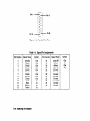
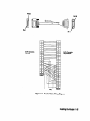
1
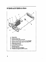
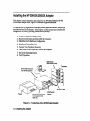
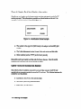
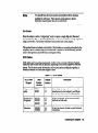
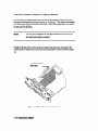
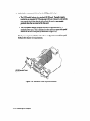
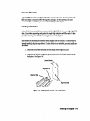
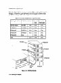
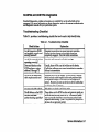
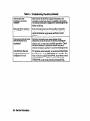
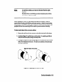
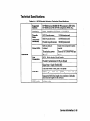
HP 28642A HP-PB SCSI
HP 28655A HP-PB SCSI/
Parallel
HP
HP
5960-3126 El091
@Hewlett-Packard Company, 1991. AI1 rights rcservcd,
Hewlett-hckard CompanymakesM wsmmty of any kind with regard to this material,btcb~dittg.but not Ihttited lo. the
implied warrantiesof merchantability and iitncsr for a panicular purpose. Hewlett-Packardshall My be liable for ertccs
containedhe-reinor for incidental or consequentialdamagesiu connectionwith thefumishing, performan~. or useof
thismamiai.
This documentcowins proprietary infommticm,which is protectedby copyright. No pan of this documentmay be
photocopied,reproduced,or translatedinto anotherlanguagewitbout the prior written consentof Hewlett-PacM. The
inform&m umbined in thii documentis subject to changewithout notice.
Print History
Edition 1, October 1991
Safety Considerations
The productand relateddocumentadoumusthe reviewed for familiarization with safety markingsand
irtt~ctions before installationand operation.
Safety Symbois
lnstntclion manual symbol. If the productis markedwith tbis symbol. refer to the
produc1mamtalsto protectthe product againsldamage.
A!
WARNING
A WARNING denotesa hazardthat can causepetsonalinjury.
CAUTION
A CAUTION denotesa hazardthat can damageequipment.
Do not proceedbeyond a WARNING or CAUTION notice until you have understoodthe
hazardousconditionsandhave takenappropriatesteps.
Grounding:
Tbe computerin which thii product is installed is a safety classI productand hasa protective earthing
terminal. There must be an uninterruptiblesafetyearth groundfrom the main power sourceto Ihe
product’sinput wiring terminals,power cord, or supplied power cordset. Wheneveril is likely that the
Protectionhas beenimpaired,dionuect the power cord until the groundhasbeenrestored.
servkblg:
Any servicing, adjustment.maintenance.or repair must be performedonly by autborizcdservice-trained
-1.
Hewlett-Packard Company
Roseville Networks Division, Roseville, CA 95678
Installation and S&vice
HP28642A HP-PB SCSI
HP 28655A HP-PB SCSI/Parallel
HP 28642A and HP 28655A at a Glance
Extractor lever.
B - Retaining (captive) screw.
C - Self-Test Fail LED (yellow), normally off.
D - SCSI port, SO-pinhigh-density connector, single-ended signals.
E - SCSI bus termination resistors,single in-line packages(SIPS).
F- PROM, socket location U52.
G - HP-PB backplane connector.
H - Switch pack of four switches,SW1
I- Termination power fuse.
J- Term Power LED (green), normally on.
K - Parallel port, not supported on MPE XL systems.
A-
2
Product Description
The HP 2S642A/HP2S655AHP-PB adapter is a computer interface card for use in
HewIett-Packard computers that use the HP-PB (HP Precision Bus) backplane. The HP
2S642Aproduct is for MPE XL systems. The HP 2S655Aproduct is for HP-UX systems.
The adapter card provides a SCSI port (Small Computer SystemInterface) for connecting
up to sevenSCSI peripherals. In addition, the adapter card provides a standard HP
parallel port for connecting an output-only device. The parallel port is not supported for
use on MPE XL systems.
Hardware Supplied
HP 28642A’
l
SCSI/parallel adapter card (2865540001)
m SCSI bus external terminator (1252.3920)
m SCSI port cable, 1 meter (5062-3383)
l
This Znstallationand ServiceManual (5960-3126)
*Note: The parallel port is not supported for use on MPE XL systems.
HP28655A
n
n
m
m
m
SCWparaIlel adapter card (2865560001)
SCSI bus external terminator (1252-3920)
SCSI port cable, 1 meter (5062-3383)
Parallel port cable, 2 meter (51804010)
This Znstallationand ServiceManual (5960-3126)
Tools and Accessories Not Supplied
n
n
n
Screwdriver, Torx T-10 or 3/164nch flat blade
HP-PB slot divider (5062-3336)
Loopback hood, single-ended SCSI signals (5061-6565)
In This Book
This manual contains installation and service information for the:
n
HP 28642A HP-PB SCSI adapter for MPE XL systems,and
I
HP 28655A HP-PI.3SCSI/Parallel adapter for HP-UX systems.
Thii manual is organized as follows:
Chapter 1 provides installation instructions. It describes,in detail, the steps that you
should follow to install this product.
Chapter 2 contains service information as well as technical specifications. If you have
problems with your card, refer to this chapter for test procedures or general service
information.
This manual is limited to installation of the adapter card only. We assumethat you have
your computer system and periphera1 manuals to complete the installation.
4
Table of Contents
Chapter 1. Installing the HP 2s642Al28655AAdapter
1, Prepare to Install the Adapter Card .........................
Observe Antistatic Precautions ..........................
Verify Product Contents .............................
Record Adapter Card Identification Information ...............
Gather Tools and Accessories Needed .....................
Slot Divider ...................................
SCSI Cables ...................................
2. Shut Down the Systemand Switch Off the Computer ...............
3. Check the Card’s Hardware Configuration .....................
Set the Desired Parity-Checking Capability ...................
.............................
SettheSCSIBusAddress
Verify that Resistor Packs are Properly Installed ................
4. Install and Connect the Card .............................
Select an Appropriate Slot ............................
Record the Slot Number .............................
Prepare the Slot For Use .............................
Removing Slot Covers ..............................
Removing Filler Cards .............................
Installing a Slot Divider ............................
Insert the Card into the Slot ...........................
Attach the Card Cables ..............................
5. Connect Your Peripheral Device(s) .........................
Connect Your Single-Ended SCSI Device(s) ..................
Terminate the SCSI Bus ..............................
A SCSI Cable Length Example ........................
Connect Your Parallel Device, if Applicable ..................
ReassembleYour Computer ...........................
6. Turn Power On to Peripherals, Then to the Computer ..............
7. Set Up the Operating System ............................
HP-UXSystems ..................................
MPE XL Systems .................................
8. VerifyOperation ...................................
1-3
l-3
l-3
14
14
l-5
l-5
l-6
l-7
l-8
l-9
l-10
l-11
l-11
l-13
1-14
1-14
l-15
l-15
1-17
1-18
l-19
1-19
l-20
1-21
1-23
l-23
l-26
l-27
1-27
1-27
l-28
5
Chapter 2. Service Information
Field Replaceable Units .................................
Exchange Assembly ................................
Board Components ................................
Other FRUs ....................................
Troubleshooting Tools ..................................
Self-Test Failure LED ...............................
TERMPWR LED .................................
SCSIPBA and CENTPBA Diagnostics .....................
Troubleshooting Checklist ............................
Removal/Replacement Instructions ..........................
Removal/Replacement of the Card .......................
Removal/Replacement of Card Components ..................
PROM and Termination SIPS ........................
Termination Power Fuse ............................
Reshipment Guidelines .................................
Technical Specifications .................................
Glossary
Index
6
2-3
2-3
24
24
2-5
2-6
2-6
2-7
2-7
2-9
2-10
2-11
2-11
2-12
2-14
2-15
1
Installing the
HP 28642A/28655A Adapter
lnstalllng the HP 28642A/28655A Adapter
This chapter contains installation instructions for the HP 28642A/28655AHP-PB
SCSI/Parallel adapter card. Figure l-l illustrates a typical installation,
The instructions are organized into the eight primary stepslisted below. Each step is
described in detail in this chapter. If the adapter card has already been installed and
configured at the factory, you may proceed directly to step 5.
1.
2.
3.
4.
5.
6.
7.
8.
Prepare to Install the Adapter Card.
Shut Down the Systemand Switch Off the Computer.
Check the Card’s Hardware Configuration.
Install and Connect the Card.
Connect Your Peripheral Device(s).
Turn Power On to Peripherals, Then to the Computer.
Set Up the Operating System.
Verify Operation.
SCSI Devices
(such as disk drives)
HP PA-RISC Computer
with HP-PB Backpla
is not supported witi
MPE XL)
Figure l-l. Typical Use of the SCSI/Parallel Adapter
1-2 Installing the Adapter
1. Prepare to Install the Adapter Card
Before installing the SCSI/parallel adapter card, perform the following:
1.
2.
3.
4.
Observe antistatic precautions.
Verify product contents.
Record adapter card identification information.
Gather tools and accessoriesneeded.
Observe Antlstatic Precautions
Thii product contains electronic components that can be damagedby static electricity. To
avoid damage,follow theseguidelines:
n
Store printed circuit assembliesin their conductive plastic bagsuntil you are ready
to install them.
m If possible, work in a static-free area.
m Handle printed circuit assembliesonly by the edges. Do not touch electronic
components or electrical traces. We strongly recommend that you use a
grounding wrist strap that is connected to the metallic chassisof the host
computer. If you do not have a wrist strap, touch the chassisbefore handling
assembliesand frequently thereafter to equalize.any static charge.
Verify Product Contents
Unpack and identify a11items supplied with the product:
n
SCSI/parallel adapter card
28655-60001
l
External SCSI terminator
1252-3920
l
SCSI port cable, 1 meter
5062-3383
m Parallel port cable, 2 meter’
5180-0010
l
Znsfaliution and Servicemanual
5960-3126
l Parallel port cable is not supplied with HP XXX.
supported on MPE XL systems.
The parallel port is not
Installing the Adapter l-3
Record Adapter Card Identification
Information
Should your card require service, its part number and date code may be neededby HP
service personnel. This information is provided on a labeled sticker on the card. An
example of a labeled sticker is illustrated in figure 1-2.
Figure 1-2. Identification Sticker Example
n
The number in the upper left (28655-6xx~cx)
is the adapter card assemblypart
number.
l
The 5-digit alphanumeric string (A-m)
is the card version and date code.
m Other numbers (such as YYYY) are for factory useonly.
Record the card’s part number and date code for future reference. Once the card is
installed, this information will be more diflicult to obtain.
Gather Tools and Accessories
Needed
Check the hardware installation manuals for your particular computer model for any
special tools or accessoriesneeded to accessthe I/O card cage. The following items may be
needed for card installation:
D Screwdriver, Torx T-10 or 3/164nch flat blade.
n
Slot divider (5062-3336),describedbelow.
m SCSI cables, described below.
1-4 Installing the Adapter
Note
You should have all of your systemand peripheral device manuals
available for refirence. There may be special systemor device
dependent requirements that are not noted here.
Slot Divider
Since this adapter card is a “single-high” card, it requires a single-high slot (Eurocard
standard slot size 3U). A double-high (6U) slot can be converted into two single-high slots
using a slot divider. Slot divider installation is described later in this chapter.
This product does not include a slot divider. Slot dividers are normally preinstalled in the
computer, and it is unlikely that you will need one. However, if one is necessary,you can
order it through the near&t HP Salesand Support Office.
SCSI Cables
SCSI cables may be purchased separately. Table l-l lists a variety of Hewlett-Packard
cables that can be used with this product, depending on the devicessupported with your
system. For the most recent information, refer to your systemconfiguration guides,or
consult the nearest HP Sales and Support OMice.
Table l-l.
Lengths
(meters)
SCSI Cables
Description
SO-pin,high-density, male connector with
thumbscrews(to host adapter), and 50-pin
low-density male connector with bail-lock.
Peripheral to
Peripheral
92222A
92222B
92222C
50-pin, low-density, male connectors with
bail-lock on both ends.
50-pin, low-density, female-to-male bail-lock
connectors.
Installing the Adapter 1-5
2. Shut Down the System and SwZtch Off the Computer
1. Before installing the card, ensure that the operating systemis shut down. Consult
your computer systemmanuals for proper shutdown procedures to avoid
corruption or loss of data.
2. Ensure that power to the host computer is off. Unplug the power cord from the
power source.
WARNING
Unless otherwise noted in your computer system manuals,
failure to properly shut down the system and remove power may
create a personnel hazard, or may result in hardware damage or
data corruption,
l-6 Installing the Adapter
3. Check the Card’s Hardware Configuration
Hardware settings for the SCSI/parallel adapter apply to the SCSIport only. There are no
hardware settings for the parallel port. Figure 1-3showsthe applicable hardware. To
check the card’s hardware, perform the following:
1. Set the desired parity-checking capability.
2. Set the SCSI bus address.
3. Verify that resistor packs are properly installed.
The SCSI/parallel adapter contains switches for setting the parity-checking capability and
the SCSI bus address of the card. The default switch settingsare “all switchesopen”,
rcsllting in:
n
parity-checking is enabled, and
= SCSI bus address is 7.
In addition, the card contains resistor packs for terminating one end of the SCSI bus.
Figure I-3. Switches and Termination Resistors
Installing the Adapter 1-7
Set the Desired Parity-Checking
CapabUity
AU devices on a SCSI bus must have the sameparity-checking capability. If anydevice on
the SCSI bus does not generate parity, then all devices on the bus, including the adapter,
must not check parity. (Although parity-checking is selectable, the adapter always
generates parity.)
Note
If there is a SCSI device that cannot match the parity-checking capability
of other devices on the bus, you must add a separateSCSI bus for that
device. An additional SCSI adapter card may be needed for this purpose.
As shown in figure 1-4, the factory setting is “parity-checking enabled”, that is, with switch
4 in the “open” position. The “closed” position will deactivate parity-checking.
Parity-Checking,
Default = Enabled
[Switch 4 is Open)
SCSI Bus Address,
Default = 7
(Switches 3,2,1, is Open)
Figure l-4. Default Switch Settings
l-8 Installing the Adapter
Set the SCSI Bus Address
There may be up to eight devices (which includes the SCSI adapter) connected to a SCSI
bus. Each device must have a unique address,from 0 to 7. The bus addressdetermines the
device’s priority on the bus. Sevenis the highest priority and zero is the lowest priority.
Switches 3,2, and 1 are used to set the adapter’s address on the SCSI bus. In binary, switch
3 represents the most significant digit. When shipped from the factory, the addressis set to
7 (switches 3,2, and 1 are each set to “l”, that is, in the “open” position) as shown in figure
l-4.
For most applications, “7” is the best choice for the adapter’s SCSI bus address. Table l-2
showsswitch positions for other possible addresses. Be sure all devices on the bus have a
different address.
Table 1-2. SCSI Address Switch PositIons
Switch
SCSI Bus 1
Address
3
2
1
0
0
0
0
0
0
1
1
0
1
0
1
0
1
2
3
1
1
1
1
0
0
1
1
0
1
0
1
4
5
6
7 (Defauh)
0 = “closed”
1 = “open”
Installing the Adapter l-9
Verify that Resistor Packs are Properly Installed
A SCSI bus has two ends betweenwhich SCSLdevices are attached. Each end of a SCSI
bus must be terminated with a resiitor network, or “terminator”. The adapter card contains
two resistor packs mounted in sockets on the card. These resistor packs act as a terminator
for one end of the SCSI bus.
Note
The SCSIport is supported for use only on the end of a SCSI bus. The
two resistor packs must be installed.
Visuaily verify that the two resistor packs are installed with the proper orientation. The
resistor packs are marked with a dot on one end and should be oriented as shown in figure
1-5.
Termination Resistors,
Figure l-5. Proper Resistor Pack Orientation
l-10 installing the Adapter
4. Install and Connect the Card
The HP-PB cardcage accommodatestwo sixes of cards: single-high (Eurocard standard
3U) or double-high (6U). The SCSI/parallel adapter is a single-high (3U) card and
requires a single-high slot. HP computers are normally shipped with single-high slots.
However, this section contains information on converting a double-high slot to two
single-high slots.
To install and connect the SCWparallel adapter into the host computer, read the steps
described below:
1. Select an appropriate slot.
2. Record the slot number.
3. Prepare the slot for use.
4. Insert the card into the slot.
5. Attach the card cables.
Select an Appropriate
Slot
Before you install the SCSI/parallel adapter into the host computer, you should understand
the following information for your particular computer model:
l
How to gain accessto your computer’s l/O card slots.
You may need to remove various covers or panelsto exposethe slots. If your
computer’s I/O slots are not readily accessible,refer to your computer installation
or hardware reference manuals to gain access.
m Proper orientation of an If0 card into the cardcage.
The HP-PB connectors are designed to prevent improper connections.
installing the Adapter l-l 1
m Authorized or recommendedslots for the SCSI/parallel adapter.
- The SCSI/parallel adapter is a standard HP-PB card. Typically, it can be
installed in any stamiard HP-PB single-high (3U) slot. However, somesystems
may contain special slots that do not support this card, or may contain
particular slots that are reserved for thii card.
- The SCSI/parallel adapter complies with HP-PB specifications for a
standard-power card. This is indicated on the card by an open circle symbol
labeled on the card’s faceplate (as illustrated in figure l-6).
Check your computer installation or hardware configuration manualsfor special
SCSI/parallel adapter slot requirements.
HP-Pa Standard Power
Symbol
Figure l-6. Standard Power Symbol Location
l-12 Installing the Adapter
n
Computer hardware limitations for l/O cards, if any.
The HP-UX and MPE XL operating systemssupport the use of this card.
However, the particular computer model into which this card is installed may
require special configuration rules due to power supply or slot limitations. This
may affect the number or combination of interface cards authorized for use. To
prevent card or systemdamage,be sure to consult your systeminstallation and
configuration manuals for authorized I/O card cageconfigurations.
n
System performance implications, if any.
All HP-PB I/O cards are guaranteed to be able to acquire the HP-PB backplane
for communication with the central processing unit (CPU) or memory. However,
the I/O card in the highest numbered slot may acquire the bus more frequently.
(That is, if all cards arbitrate for the bus continuously, the card in the highest slot
will acquire it about 50% of the time.)
The SCSI/parallel adapter is a high-performance card. In general, if your
applications require high performance through this card and you are not
concerned about the performance of other I/O cards in your system,then select
the highest numbered slot. Otherwise, any other allowed slot would be suitable.
You should check your systeminstallation or configuration manuals for any
recommended configurations.
Record the Slot Number
The HP-PB slot number is used to calculate the card’s hardware address during system
configuration. The slot number is labled on the computer and may be an even or odd digit.
Hexadecimal notation may be used. If the slot number will be difficult to obtain once the
computer is reassembled,record the number now.
Installing the Adapter 1-13
Prepare the Slot For Use
To prepare a slot, you must first remove the metal slot cover. Then, if a plastic frl!er card is
installed in the slot, remove it. (Retain slot covers and filler cards- they should be installed
when slots are not in use.) If a slot divider is not installed, you must install one. Figure l-7
shows the applicable hardware.
Removing Slot Covers
Using a Torx T-10 or 3/164nch flat-blade screwdriver, unscrew the slot cover retaining
screws and remove the slot cover for the selected slot.
Slot Divider
Filler Card
Figure 1-7. Slot Cover, Filler Card, and Slot Divider
t-14 Installing the Adapter
Removing Filler Cards
A plastic “filIer” card is normally installed when a slot is not in use. In somesystems,the
filler card helps to channel airflow through the cardcage. In these systems,you must
remove the filler card before you can install the SCSI/parallel adapter.
Installing a Slot Divider
A slot divider is an assemblythat converts a double-high (6U) slot into two single-high (3U)
slots. It provides supporting card guides for single-high adapters and filler cards. It also
provides retaining screw holes for securing slot covers and adapters.
Slot dividers are normally pre-installed when shipped from the factory. If a slot divider is
already installed, skip the steps below. If a slot divider is not installed, you must install one
as follows:
1. Insert the slot divider carefully into the empty double-high (6U) slot.
2. Align the slot divider’s alignment pin with the hole in the locator bracket on the
backplane. See figure l-8.
LocatorBracket
ignment Hole
Figure 1-8. Aligning Slot Divider For Installation
Installing the Adapter l-15
3. Pressthe slot divider until its retention clips clamp onto the locator bracket as
illustrated in figure 1-9.
Figure 1-9. Slot Divider Mated With Backplane Bracket
l-16 Installing the Adapter
Insert the Card into the Slot
To install the adapter into its slot, proceed as follows:
1. Inspect the %-pin connector at the back of the slot on the backplane. Ensure that
there are no bent pins.
2. With both hands,grasp the card by its edgesor faceplate. Do not touch electronic
components or electrical traces.
3. Insert the card into the slot. Be sure the card is properly aligned with the card
guides on the slot divider and cardcage wall.
4. Ensure that the extractor levers are flush against the faceplate (in other words, not
protruding out).
5. Slide the card ail the way into the cardcage until it reaches the backplane
connector. Be sure that card components are not obstructed in any way.
6. Pressfirmly on the extractor levers (or on the faceplate) until you feel the card
slide fully into place.
CAUTION
The useof excessivepressure may damage the card and the backplane.
If you feel resistance,check for obstructions, and reverify that the
connector pins are straight. Ensure that the card is correctly engagedin
the card guides. If the problem persists, get help.
7. Once the card is fully seated in its slot, use a screwdriver to engage and tighten the
two retaining screwson the faceplate. These screwssecure the card to the
cardcage.
Installing the Adapter 1-17
Attach the Card Cables
Figure l-10 showsa typical installation with both the SCSI port and parallel port cables
attached (the use of the parallel port is not supported for MPE XL systems).
CAUTION
Do not connect serial cables (for example, RS-232cables) to the parallel
port. Connecting serial cables can damagethe SCSI/parallel adapter.
Note
SCSI cableswith high density squeeze-latch or thumbscrewconnectors
can be attached to the SCSI port. However, cableswith thumbscrew
connectors are recommended for improved reliability. The SCSIcable
supplied with this product provides a thumbscrew connector.
\
Thumbscrews
SCSI Port Cable
Parallel Port Cable (not
auupportedon
MPE XL systems)
Figure l-10. Cable Connections to SCSI and Parallel Ports
1-18 Installing the Adapter
Connect Your Peripheral Device(s)
You can connect SCSI devices (single-ended devicesonly) to the SCSI port, and a parallel
communication device to the parallel port. (The parallel port is not supported for use on
MPE XL systems.) The following stepsare describedbelow:
1. Connect your single-ended SCSI devices.
2. Terminate the SCSI bus.
3. Connect your parallel device (ii applicable).
4. Reassemble your computer.
Connect Your Single-Ended
SCSI Device(s)
When connecting SCSI devices, follow these guidelines:
n
Verily that the host system is shut down. There should be no data transfer activity
on the SCSI bus.
m Verify that power is off to the peripheral device before connecting it to the SCSI
bus.
n
Verify that your peripheral devices usesingle-endedSCSIbus signals only.
8 Check whether your device contains internal SCSI bus terminators, or requires
special terminators. If so, refer to your device manuals for instructions on how to
prevent excessiveor improper SCSI bus termination.
CAUTION
Only the two ends of a SCSI bus should be terminated. Excessiveor
improper termination may overload the SCSI port’s termination power
(“TERMPWR”) circuitry. This may result in blowing the TERMPWR
fuse on the adapter, or damagingtransceivers on any attached device
(including the adapter). Refer to device manuals to ensure they operate
properly on the SCSI bus.
Installing the Adapter l-19
Set switches or jumpers on your device(s) as appropriate. Be sure each SCSI
device has a unique SCSI address.
For optimum noise immunity, any device that supplies termination power should
be enabled to do so. If at least two devices supply termination power, Locatethem
at each end of the SCSI bus.
Connect the device end of the SCSI port cable (50-pin, low-density SCSI
connector) to the first SCSI device. If applicable, connect subsequentdevices.
The connection method is often called “daisy-chaining”. Refer to your device
manuals for proper connection to a SCSI bus.
Use active SCSI terminators.
Use HP-supplied SCSI cables.
Minimize the SCSI bus length. However, do not usedevice-to-device cablesthat
are less than 0.5 meter.
Do not exceed the maximum single-ended SCSIbus length of 6 meters, which
includes the SCSI port cable a& any internal device cabling. (The SCSI/parallel
adapter has an internal SCSI cable length of 0.1 meter.)
Do not exceed the maximum number of devices supported for your particular
system.
Terminate the SCSI Bus
Unless the SCSI bus is properly terminated, the bus will not operate reliably. Terminators
provide matching impedance and bias the bus signat lines.
This product includes an external SCSI bus terminator assembly,part number 1252-3920,to
terminate the peripheral end of the SCSI bus. The terminator assemblycontains a SO-pin,
low density, male connector. Adapting connectors can be used to accommodateother
types of SCSI connectors. Consult HP for availability,
As illustrated in figure l-11, install the terminator on the end of the SCSI bus (opposite the
SCSI/parallel adapter).
l-20 lndalling the Adapter
CAUTION
Only the two ends of a SCSI bus should be terminated. Excessiveor
improper termination may overload the termination power circuitry on
the SCSI port. This may result in blowing the TERMPWR fuse on the
SCSI/parallel adapter, or may damagetransceivers on any attached
device (including the adapter). Refer to device manuals for proper
device operation on the SCSIbus.
Terminator Resist0
Install External
Termlnator
Figure l-l 1. Install External Terminator on Last Device
Installing the Adapter 1-21
A SCSI Cable Length Example
Table l-3 and figure 1-12demonstrate how to calculate SCSIbus cable lengths for a typical
installation. The SCSI 0.5 m cable (HP 92222A) used in the example is available through
your HP Sales and Support Office. Other lengths are also available.
Table 1-3. Example of SCSl Cable Length Calculation
Cable to next device
HP Device #4
HPDevice13
HP Device #2
Figure 1-12. SCSI Bus Example
l-22 Installing the Adapter
,
Connect Your Parallel Device, If Applicable
Output-only parallel devices,such as common printers, can be connected to the parallel
port. Figure l-13 and table l-4 show the signals definitions of the parallel port connector.
Note
For MPE XL systems,do not use the parallel port. The parallel port is
not supported for useon MPE XL systems. Proceed directly to step 6,
“Turn Power On to Peripherals, Then to the Computer.”
The parallel port cable contains a 25pin connector for connecting to the parallel port, and
a Spin connector for the peripheral device. Figure 1-14showsthe parallel port cable and
wiring diagram.
CAUTION
For reliable operation, do not use a parallel port cable that is longer than
two meters.
Reassemble your computer
Unless there are other adapter cards to install, reassembleyour computer. Be sure to
reinstall protective panels or covers.
Installing the Adapter 1-23
Pin 1
Pin 14
Pin 13
Pin 25
Figure 1-13. Parallel Port Pins
Table 1-4. Signal Pin Assignments
Pin Number
Signal Name
In/Out
Pin Number
Signal Name
In/Out
1
2
3
4
5
6
7
8
9
10
11
12
13
nStrobe
Data1
Data2
Data3
Data4
Data5
Data6
Data7
Data8
nAck
Busy
PError
Select
out
out
out
out
out
out
out
out
out
In
In
In
In
14
15
16
17
18
19
20
21
22
23
24
25
nAutoFd
nFault
nReset
nSelectIn
Ground
Ground
Ground
Ground
Ground
no connect
Ground
Ground
out
In
out
out
l-24
Installing the Adapter
II
Pin25
::0.
Pin 36
;.
%
Fin 1
Pin 1
25Pin Connector,
Host End
B-Pin Connector,
Peripheral End
Figure 1-14. Parallel Cable Wiring Diagram
Installing the Adapter l-25
Turn Power On to Peripherals, Then to the Computer
Before turning power on, follow these steps:
1. Verify that a11cables are connected and securely fastened.
2. Turn power on to your peripheral devices before your computer.
Refer to your peripheral and computer installation manuals for information on
turning power on. In general, plug your power cords first into the load (your
peripheral or computer), then into the power source (such as the electrical wall
outlet). Then turn on your computer power switches as appropriate.
When the computer’s power is switched on, power is supplied to the SCSI/parallel adapter
through the HP-PB backplane. For operation of the light emitting diodes (LEDs) on the
card, refer to chapter 3, Servicebtfonnation.
CAUTION
After power is switched on, termination power (“TERMPWR”) is
supplied to the SCSI bus. Do not switch power on or off any device
connected to an active SCSI bus. Similarly, devices should not be added
to, or removed from, an active SCSI bus. Failure to comply may result in
data corruption or loss, or damageto hardware.
1-26 Installing the Adapter
7. Set Up the Operating System
Before you can use your devices, the SCSI/parallel adapter card and peripheral devices
must be configured into the operating system. Depending on your system,this may or may
not be performed automatically during the boot process. Refer to your system
administration manuals for current procedures.
HP-UX Systems
On HP-UX systems,refer to your HP-LX Installing Pefipherals Guide, B2437-90005,and
HP-UXSystemAdministration TasksGuide, B2437-90006.
If you manually generate a new kernel, you may need the names of the software drivers for
the SCSI/parallel adapter card. The driver namesare:
n
SCSI module: scsil
n
Parallel module: cent0
MPE XL Systems
On MPE XL systems,refer to your SystemStartlIp, Configuration, and Shutdown Reference
Manual, 32650-90042.On MPE XL systems,you should not need the name of the SCSI
module driver.
Installing the Adapter 1-27
8. Verify Operation
To verify card operation, observe the light indicators:
n
The yellow self-test LED should be off.
n
The green termination power LED should be on.
In addition, you can check for proper operation of eachport by running one of your
application programs that writes to or reads from your peripheral device(s). If proper
operation cannot be verified, refer to chapter 2, Service Information, and to your system
troubleshooting manuals. If operation continues to fail, call your Hewlett-Packard Sales
and Support Office.
1-28 Installing the Adapter
2
Service Information
Service Information
This chapter provides the following service and reference information:
m Field Replaceable Units
8 Troubleshooting Tools
H Removal/Replacement Instructions
n
Reshipment Guidelines
n
Technical Specifications
2-2 Service Information
Field Replaceable Units
Field replaceable units (F’FWs) are assembliesor componentsthat are authorized for field
replacement. Field replacement of faulty units must be performed by authorized service
personnel. See figure 2-l for FRUs associatedwith the adapter card.
TERMPWRFuse
Flgure 2-1. Location of Board Component FRUs
Exchange Assembly
The adapter card assemblymay be replaced under the HP board exchangeprogram.
Assembly part numbers are listed below:
New adapter card assembly:
Exchange adapter card assembly:
2%655-6ooOl
28655-69001
Service Information
2-3
Board Components
The foIIowing board components are available for replacement (see figure 2-l for location):
PROM (location U52):
28655-81001
Fuse, termination power:
2110-0517
Onboard SCSI terminator,
(single in-line packages,SIPS): 1810-0676(two installed)
Other FRUs
Other PRUs associatedwith this product include the following:
SCSI card cable, 1 meter:
External SCSI bus terminator:
Loopback hood:
Parallel cable,* 2 meters:
5062-3383
12523920 (active, single-ended)
5061-6565(single-ended)
51804010 (sameas HP 92284A)
* Not applicable for the HP 28642A product on MPE XL systems. MPE XL
systemsdo not support the use of the parallel port.
2-4 Service Information
Troubleshooting
Tools
Troubleshooting tools are used to identify faulty FRUs. For this product, the following
tools are described below
B Self-Test failure LED (see figure 2-2)
n
TERMPWR LED (see figure 2-2)
8 scsipba and centpba diagnostics
H Troubleshooting checklist
CAUTION
In some systems,the light emitting diodes (LEDs) on the card may not
be visible without exposing the I/O cardcage. Unless otherwise
permitted, operating the computer systemwith the I/O cardcage exposed
should be performed by authorized service personnel only.
Self-lestFailure
LED (vellow)
Figure 2-2. Location of LEDs
Service Information
2-5
Self-Test Failure LED
The Self-Test Failure LED is yellow and will indicate card test failures whenusedby fhe
host system. Card self-test code contained in PROM on the card is uploaded to the host
and run under host control.
Note
The use of the card’s self-test code is systemdependent. In some
systems,for example, the self-test must be invoked by the operator. In
other systems,it may be run automatically by the system,but only if a
boot failure occurs.
In addition, the use of the Self-Test Failure LED is systemdependent. In
somecases,the LED will operate as described here. In other cases,
systemmessageswill be displayed on the systemconsolein place of LED
operation. Refer to your systemreference manuals.
When card self-test is executed, the LED will tight and subsequently turn off if self-test
passes. When used by the system,the card self-test has failed if:
n the LED never turns on, or
n
the LED turns on and remains on.
If card self-test fails, check the TERMPWR fuse. Otherwise, replace the card.
TERMPWR LED
The termination power (TERMPWR) LED is green and indicates that the card is
supplying termination power to the SCSI bus. During proper operation, this LED should
be on.
If this LED is off, there may be a problem with the TERMPWR circuitry. Possible faults
include a blown TERMPWR fuse, a faulty card, or a faulty cable connection. Instructions
on how to replace the TERMPWR fuse is described later in this chapter.
2-6 Service Information
SCSIPBA and CENTPBA Diagnostics
Standard diagnostics, scsipba andcentpba, are available for use by authorized service
personnel. For more information on these diagnostics, refer to the systemtroubleshooting
and diagnostic manuals for your particular system.
Troubleshooting
Checklist
Table 2-l provides a troubleshooting checklist that can be used to help identify faults.
Table 2-l. Troubleshooting
Check list item
Are all connectors (SCSI
and parallel) properly and
securely fastened?
Checklist
Explanation
Marginal connections can causeimproper operation.
Ensure that the adapter and retaining screwsare
completely engaged. Check all cable connections.
Are all the external devices Run their self-tests and verify their settings.
operating correctly?
Does each device on the
SCSIbus have a unique
address(0 through 7)?
Usually, there will be a set of switcheson the device.
Conflicting addressesmay causeintermittent or complete
failures in transmission.
Are SCSI bus length and
cable requirements met?
Minimize the SCSI bus length. Do not exceed6 meters,
which includes cable lengths inside each peripheral (the
SCSI/parallel adapter’s internal SCSIbus length is 0.1
meter). However, do not use device-to-device cables that
are shorter than 0.5 meters.
Are you using HP cables?
HP cables are wired to minimize noise.
Do all devices on the SCSI
bus have the same
parity-checking capability?
If any device on the SCSI bus does not generate parity, no
device on that bus may check for it A mismatch causes
non-recoverable hardware errors becauseparity is both
expected and missing. (Note: Only somevery early SCSI
devices do not generate parity.)
Service Information
2-f
Table 2-I. Troubleshooting
Checklist (continued)
Are the SCSI bus
terminators correctly
installed?
Both ends of the SCSI bus require termination. The
terminator on the host adapter is installed at the factory.
An external terminator is supplied for terminating the last
device on the bus.
Does any device require a
special SCSI terminator?
Some external devices may have peculiar termination
requirements. The device manual should explain any
special termination requirements and how to avoid
problems.
Does any peripheral device
have an internal SCSI
terminator?
Excessivetermination may cause damage to the
transceivers of all the devices on the bus, including the
adapter card, or may causeunreliable operation. Check
the device manuals to determine whether they have
internal terminators and how to avoid overloading the bus.
Are all devices that can
supply termination power
configured to do so?
For optimum noise immunity, we recommend that devices
be configured to supply TERMPWR when possible. If at
least two devices supply TERMPWR, locate them at each
end of the SCSI bus, Additional devices that supply
TERMPWR can be evenly distributed along the bus.
2-8 Service Information
Removal/Replacement
Instructions
This section describes removal and replacement instructions for the following items:
l
The SCSI/parallel adapter
n
SCSI/parallel adapter components
WARNING
Unless otherwise noted in your system manuals, removal of the
interface card should only be done with power removed from the
host computer. Failure to comply may result in an electrical
shock hazard, or in damage to the hardware.
CAUTION
The card contains electronic componentsthat can be damaged by static
electricity. To avoid damage,follow theseguidelines:
Store printed circuit assembliesin their conductive plastic bags.
If possible,work in a static-free area.
Handle printed circuit assembliesonly by the edges. Do not
touch electronic componentsor electrical traces. We strongly
recommendthat you use a grounding wrist strap that is connected
to the metallic chassisof the host computer. If you do not have a
wrist strap, touch the chassisbefore handling assembliesand
frequently thereafter to equalize any static charge.
Service Information
2-9
Removal/Replacement
of the Card
For card removal, follow the procedures below:
1. Before removing the card, ensure that the operating systemis shut down and that
power to the host computer is off. Consult your computer systemmanuals for
proper shutdown procedures to avoid corruption or loss of data.
2. Access the f/O cardcageaccording to instructions in your systemmanuals.
3. Disconnect the cablesfrom the card.
4. Unscrew the two retaining screwsthat secure the card to the cardcage.
5. Simultaneously lift both extractor levers on the card. This will disconnect the card
from the HP-PB backplane connectors.
6. Slide the card out of its slot.
To install a replacement card, follow the procedures described in chapter 1.
2-10 Service Information
Removal/Replacement
of Card Components
Replaceable card components are socketed to facilitate their removal and replacement.
PROM and Termlnation SIPS
CAUTION
Observe antistatic precautions when handling these components. When
removed from the board, these components should be placed in antistatic
containers (such asconductive box 15404929 with antistatic foam insert
92112794). Minimize touching the connector pins.
It may be necessaryto remove Programmable Read Only Memory (PROM) devices and
termination resistors for the following reasons:
n
The components may be faulty.
H PROMS must be replaced when upgrading to newer versions.
The PROM firmware version is displayed during systemboot and can
also be determined from the,scsipbadiagnostic.
Note
To remove these components, proceed as follows:
1. Remove the card from the host computer as described earlier in thii chapter.
2. Use a “chip extractor” or similar tool to gently pry and remove each component
from its socket.
CAUTION
Excessiveprying and pressure can damagethe component or its socket.
Use care during removal.
Service Information
2-l 1
To install replacement components, proceed as follows:
1. Identify the proper socket location for the replacement component.
2. Note the half-circle notch or identification mark located on one end of the
component. When installed, the component must be oriented so that its notch or
mark is in the samedirection as a similar notch or mark on the socket.
3. Ensure that the component’s contact pins are aligned with the socket’s
receptacles. You may need to adjust the pins (bow them inward or outward) for
proper alignment.
4. Gently press the component into place to properly seat the pins.
CAUTION
If pressure is not uniformly applied, the pins on one side or the other may
buckle and collapse without making proper electrical contact. If this
happens,remove the component, straighten the pins, and try again. If
damagewas extensive, you may need a new component.
Termination Power Fuse
-
WARNING
For continued protection, replace only with a fuse of the same
type and rating.
If the termination power (TERMPWR) fuse blows, the SCSI port will no longer supply
termination power to the SCSI bus, and the green TERMPWR LED will turn off.
2-12 Service Information
Note
An open fuse condition can be also be determined from the scsipba
diagnostic.
If another device on the SCSI bus provides termination power, the bus
can continue to operate normally.
Before replacing the TERMPWR fuse, identify the reason for the failure. Check for
sonrces of short circuits on the SCSI bus cables and connectors. Check for proper mating
of contact pins on the SCSI bus cables. Be sure that power is off on the host computer and
peripheral devices when connecting SCSI bus cables to prevent inadvertent shorting.
To remove and replace the fuse, proceed as follows:
1. Remove the card from the host computer asdescribed previously in this chapter.
2 As shown in figure 2-3, pull the fuse out of its socket. It is usually a good idea to
verify that the fuse is open by using a continuity tester.
3. To install the replacement fuse,carefully align the two contact pins with the socket
holes. Then simply press the fuse in. The fuse has no polarity, so the pins can go
into either socket hole.
Wiggle fuse ollghlly whllr pulling lt
Flgure 2-3. Replacing the TERMPWR Fuse
Service Information
2-13
Reshipment Guidelines
If any item of the product is to be returned to Hewlett-Packard for any reason,contact your
HP Safesand Support Office to coordinate the return.
When returning any item, attach a tag that identifies the owner and indicates the reason for
shipment. Include the part number of the item and date code if applicable.
Pack the item in the original factory packaging material if available, or a suitable substitute.
Provide antistatic protection to applicable components or assemblies.
2-14 Service Information
Technical Specifications
Table 2-2 SCSI/Parallel Adapter Technical Specifications
Supported
Systems
HP 9bOOSeries 600/800HP-PB computers (HP-UX);
I HP 3000 Series 900 HP-PB computers (MPE XL).
Standards
;
Transfer
Rates
(supported
maximum)
1Parallel Asynchronous:
Status LEDs
330 Kbyteskecond
Self-test failure
(Yeflow)
Under host computer system
control
Termination power
Turns off if TERMPWR fuse
1(green) -
General
Port
Connectors
ISCSI: High-density 50-Din female
IParallel: Subminiature D 25pin
female
Signal type: Singie-Ended (SE)
Data bus width: 8 bits, plus l-bit parity
SCSI Bus
SCSI length on PCA: 0.1 m (SCSI port cable is 1.0m)
Supported SCSI bus length: 6 m maximum (includes
any internal lengths in ail devices)
ISCSI mode
I Initiator only
Service information
2-15
Table 2-2. SCSI/Parallel Adapter Technical Specifications (continued)
C
IElectrical
Voltage
Current (Typical)
+5 Vdc
0.75 A
3.75w
+ 12 Vdc
OA
ow
-12 Vdc
OA
ow
IPhysical
Length
24 cm (9.4 in)
Width
13cm (5.1 in)
Thickness
3.1 cm (1.2 in)
Weight
0.26kg (9 oz)
Operating
IEnvironmental
NonOperating
Eiectromagnetic
2-16 Service Information
Power ~tcal)
Temperature
0°C to 55°C
Relative
Humidity
1595% @ 40°C
(noncondensating)
Altitude
4.6 km (15,000ft)
Temperature
-40°Cto 70°C
Relative
Humidity
90% @ 65°C
Altitude
4.6 km (15,000ft)
When operating under authorized
conditions, complies with FI’Z-1046
(VDE Level B), VCCI Class1,
CISPR-22 ClassA, and FCC Class A
for radiated and conducted emissions.
Glossary
adapter, adapter card
An add-on computer interface card and circuitry that provides the physical
connection and data translation between the host computer’s I/O bus and external
devices or networks.
ANSI
American National Standards Institute.
backplane
For an I/O bus, the computer’s circuitry and connectors to which adapter cards
connect. The SCSI/parallel adapter card is supported on HP Precision Architecture
RISC computers that usethe HP-PB backplane. Seealso, HP-PB.
balanced signal
See differential signal.
bus
The electrical hardware and circuitry for transferring data, addressand control
signals between hardware modules or devices.
configuration
The arrangement of a computer systemor subsystemand its elements to allow proper
operation or to implement specific functionality. The term configuration may refer to
both hardware and software.
console
The ASCII terminal, or personal computer emulating an ASCII terminal, that is
connected to the host computer for systemadministration (such as for configuration,
monitoring and troubleshooting).
Glossary 1
device
In this manual, refers to the peripheral units that are attached to the SCSI/parallel
adapter card.
device adapter
Seeadapter.
differential signal
Also referred to as “balanced signal”. During electrical transmissionand reception,
signals are detemined by the difference between two lines that are both at different
voltages relative to ground. Differential SCSI signalscan be used over longer
distances and at higher data rates. A differential SCSI bus is incompatible with a
single-ended SCSI bus. Therefore, differential SCSI devicesmay not be usedwith the
SCSI/parallel adapter card. See also, single-ended signal.
filler card
In some HP-PB computers, a removable plastic plate that is installed in HP-PB I/O
slots when the slot is not in use.
FRU
Field Replaceable Unit. The lowest level of hardware supported for field
replacement, such as to effect repair.
hardware path
The collection of hardware addressesthat uniquely identify hardware elements (such
as adapter cards and peripheral devices) to the computer system.
high-density connector
In reference to the adapter card’s SCSI port, a 50-conductor connector consisting of
two rows of 25 contacts with adjacent contacts 1.27mm (0.05in) apart. Seealso,
low-density connector.
host
In this manual, the computer in which the adapter card is installed.
2 Glossary
host adapter
Seeadapter.
HP-PB
Hewlett-Packard Precision Bus. The data, control, and addressing signal lines for
input/output operation on Hewlett-Packard PA-RISC computer systems. HP-PB is
the 32-bit system-architectedbus through which the CPU, memory, and input/output
adapter cards communicate.
HP-PB card
Seeadapter.
Interface card
Seeadapter.
UO
Input/Output. The computer subsystemthrough which data communications with
external devices is performed.
IODC
I/O Dependent Code. In PA-RISC computers, IODC is ROM-based firmware on an
adapter card that is used for supplying card-dependent information to the host
computer. Thii code may contain test routines that check operation of the card.
LED
Light Emitting Diode, a semiconductor component that emits light when electrically
activated to serve as an indicator of operation or state.
loopback
Generally, the processof transmitting known data, and comparing received data with
expected results (normally used during troubleshooting, test, or verification
procedures).
Glossary 3
loopback hood
A special connector with signal lines configured to allow loopback testing of the
adapter card.
low-density connector
In reference to the SCSI bus, a Xl-conductor connector consisting of two rows of
ribbon contacts spaced 2.16 mm (O.OsSin) apart. See also, high-density connector.
parallel port
The Z-pin connector on the SCSI/parallel adapter card for S-bit parallel data
communications with an output only device, such as a printer.
PA-RISC
Hewlett-Packard’s Precision Architecture Reduced Instruction Set Computing
computer systems.
A method to check that data was accurately transmitted and received. Usually, the
tranmission logic sums the transmitted data unit and, based on the summation,
appends a parity bit. The receiver logic sums the received data unit and, based on its
summation, compares the parity bit. The adapter card’s SCSI port can have its
parity-checking ability enabled or disabled.
Precision Bus
See HP-PB.
SCSI
Small Computer SystemInterface, often pronounced “skuq”.
and SCSI-2.
SCSI-1
Complies with the SCSI specification X3.131 - 1986.
4 Glossary
Refers to both SCSI-1
SCSI-2
Complies with the SCSI specilication X3.131 - 1990. SCSI-Z provides extensions and
further standardization of SCSI-l.
SCSI address
The octal representation of the unique address (0 to 7) assignedto each device on an
SCSI bus. For bus arbitration, higher addresseshave priority over lower addresses.
SCSI addressesare typically assigned during installation. The host adapter is
typically assigned“7”.
SCSI bus
The collection of unbroken SCSI signal limesthat interconnect SCSI devices
SCSI ID
SCSI identification. The bit-significant representation of the SCSI addressreferring
to one of the bus signal lines DB (7 through 0). Seealso, SCSI address.
self-test
A diagnostic test to check hardware components and circuitry.
slot divider
An assemblyused to convert a double-high (6U) HP-PB I/O slot into two single-high
(3I.l) slots. Also referred to as a “two-board adapter”.
sfnglesnded signal
Also referred to as “unbalanced signal”. During electrical transmission and
reception, signals are detemined by the voltage of a single line relative to a common
ground. Becauseof electrical noise caused by ground loops at evenshort distances
(common mode noise), single-ended SCSI signals are limited to 6 meters maximum
and lower data rates. A single-ended SCSI bus is incompatible with a differential
SCSI bus. Therefore, useonly single-ended SCSI devices with the SCSI/parallel
adapter card. Seealso, differential signal.
Glossary 5
system administrator
The person who managesor controls the configuration and operation of a computer
system.
terminator
An assemblythat contains a resistive network to terminate the peripheral end of a
SCSI bus. The peripheral end of the SCSI bus may not need a terminator if the last
peripheral device on the bus already contains SCSI termination resistors.
termination
To complete the bus circuitry at each end of a SCSI bus, the electrical lines (at each
end only) must be terminated with a resistive network. The HP-PB SCSI/parallel
adapter contains termination resistor packs on the card and must be located at one
end of the SCSI bus. See aIso, terminator.
two-board adapter
Seeslot divider.
unbalanced signal
Seesingle-ended signal.
6 Glossary
Index
A
accessories...l-4
adapter
configuration...l-7
connecting...1-11
exchangeassembly..23
hardware address...&l3
HP-PB specifications...l-12
HP-UX drivers...l-27
inserting into the computer...l-ll, l-17
part number...13,2-3
removaVreplacement,..2-10
storing...13
version...14
antistatic precautions...l3,2-9
attaching the cable...l-18
B
bus terminator...%20
Seealso terminator
Index - t
C
cable
connecting to the card...l-18
paraliel...l-3, l-23,2.4
part number...l-3,1-S, l-21
SCSI...l-3,1-18,2-4
SCSI bus length...l-20,1-21
troubleshooting...2-7
card version...14
checklist, troubleshooting..27
components
removing and replacing...2-11
replaceable...2-4
computer power
during installation...l-6
during removaI/replacement...2-10
configuration
c.ard...l-7
hardware...l-7
operating system...l-27
systemdependencies...l-13
troubleshooting...2-7
connecting peripheral devices...l-19
connecting the card...l-11
connectors...2-15
D
daisy-chaining...120
date code...l-4
device adapter manager
Seedrivers
diagnostics...2-5,2-7
double-high slot...l-5,1-11, l-15
drivers
adapter card...l-27
2 - Index
electrical specifications..216
electromagnetic specifications..2-16
environmental specifications..516
exchange assembly
part number...2-3
F
field replaceable units
se-eFRUS
filler card...l-14
removing...l-15
FRUs...2-3
part numbers...2-4
fuse...24
removaUreplacement...2-12
TERMF’WR LED...2-6
H
hardware
address...l-13
configuration...l-7
HP Precision Bus
SeeHP-PB
HP-PB
specitications,..l-12
HP-UX system...2-15
configuration...127
I
identification information...l-4
installing
adapter card...l-11
resistor packs...l-10
Index - 3
L
LEDs...2-6
troubleshooting...2-5
verifying card operation...l-28
light emitting diodes
SeeLEDs
loopback hood...2-4
MPE XL system...2-15
configuration...l-27
0
operating system...l-13
configuration.,.l-27
supported...2-15
P
parallel
cable...13,1-18,2-4
connecting devices...123
parity checking...l-7,1-8
part number
adapter card components...24
exchange assembly...23
product contents...l-3
performance...‘t-l5
systemconsiderations...l-13
peripheral devices
connecting...l-19
physical specifications...2-16
4 - Index
power
during instailation/removai...l.6,1-19, l-26,2-10
symbol for standard power sIot...l-12
product contents...13
PROMS
removaVreplacement..2-11
R
removalkeplacement instructions..2-9
adapter card...2-10
board components..2-11
TERMPWR fuse...2-12
replaceable board components...2-4
reshipment..2-14
resistor pack...&10
S
SCSI
address..&7,1-9
bus length requirements..&20,1-21
cable..&3,1-S, l-18,24
hardware [email protected]
peripheral devices...&19
single-ended devices...l-19
terminators...l-20
troubIeshooting..2-7
self-test failure LED...2-6
shut down
See systemshut down
single-ended SCSI signais...l-19
$&high
slot...l-5,1-ll, l-15
choosing a slot...l-11
cover...l-14
number...l-13
Index - 5
slot divider..S-4,1-5
instaBiig...l-15
specifications...2-14
storing adapter cards...l-3
switch
default settings&S
hIcation...1.7
&ylrlbo~
standard power card..&12
systemperformance considetations...l-l3
systemshut down
during installation/removal..J-6,1-19,2-10
T
technical specifications...2-14
termination power
SeeTERMPWR
termination resistors...l-7,2.4
terminator...l-3, l-20,2-4
troubleshooting..2-8
TERMPWR
fuse...2-6,2-12
LED...26
precautions...l-19
troubleshooting..2-8
tools and accessories,.&4
troubleshooting...2-5
troubleshooting...2-5
checklist...2-7
two-board adapter
Seefiller card
V
verifying operation,..XB
6 - Index
HEWLETT:,’
PACKARD
Reorder No. or
Manual Part No.
5960-3126
El091
Printed on
Recycled Paper
Illllllll
Illlll
IIIlllll
llllllllll
Ill11111
IIIll1
Ill1
5960-3126