1
Use, Care, and Installation Guide
www.zephyronline.com
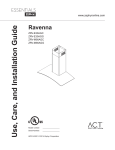
Tempest I
AK7000BS
AK7036BS
AK7042BS
Model number:
Serial Number:
Date of Purchase:
Sales Dealer:
APR14.0301 © 2014 Zephyr Corporation
READ AND SAVE THESE INSTRUCTIONS
www.zephyronline.com
INSTALLATION
Ducting Calculation Sheet .......................................
Mounting Height & Clearance................................
Ducting Options ...........................................................
6SHFL¿FDWLRQV ...............................................................
Mounting the Range Hood ......................................
Horizontal Conversion...............................................
PBD-1200A Dual Blower..........................................
5
6
7
8
9-10
11-12
13-14
FEATURES & CONTROLS
Touch Controls & Features ..................................... 15-17
Optional Remote Control ......................................... 18
MAINTENANCE
Cleaning, Filters & Recirculating .......................... 19
Lights ................................................................................ 20
TROUBLESHOOTING................................................................ 21
WIRING DIAGRAMS ................................................................... 22
FAN CURVE DIAGRAMS ......................................................... 23-24
LIST OF PARTS AND ACCESSORIES .............................. 25
1
Table of Contents
SAFETY NOTICE ................................................................. 2-3
LIST OF MATERIALS....................................................... 4
www.zephyronline.com
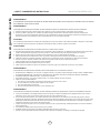
Important Safety Notice
READ AND SAVE THESE INSTRUCTIONS
WARNING
TO REDUCE THE RISK OF FIRE OR ELECTRIC SHOCK, DO NOT USE THIS FAN WITH ANY SOLID-STATE CONTROL DEVICE.
WARNING
TO REDUCE THE RISK OF FIRE ELECTRIC SHOCK, OR INJURY TO PERSONS, OBSERVE THE FOLLOWING:
a. Use this unit only in the manner intended by the manufacturer, if you have questions, contact the manufacturer.
b. Before servicing or cleaning unit, switch power off at service panel and lock panel to prevent power from being switched on accidentally.
When the service disconnecting means cannot be locked, securely fasten a prominent warning device, such as a tag, to the service
panel.
CAUTION
For general ventilating use only. Do not use to exhaust hazardous or explosive materials and vapors. Take care when using cleaning
agents or detergents. Suitable for use in household cooking area.
WARNING
TO REDUCE THE RISK OF RANGE TOP GREASE FIRE:
a. Never leave surface units unattended at high settings. Boilovers cause smoking and greasy spillovers that may ignite. Heat oils slowly
on low or medium settings.
E $OZD\VWXUQKRRG21ZKHQFRRNLQJDWKLJKKHDWRUZKHQÀDPLQJIRRG
F &OHDQYHQWLODWLQJIDQVIUHTXHQWO\*UHDVHVKRXOGQRWEHDOORZHGWRDFFXPXODWHRQIDQRU¿OWHU
d. Use proper pan size. Always use cookware appropriate for the size of the surface element.
H .HHSIDQ¿OWHUVDQGJUHDVHODGHQVXUIDFHVFOHDQ
f. Use high setting on hood only when necessary.
g. Don’t leave hood unattended when cooking.
h. Always use cookware and utensils appropriate for the type of and amount of food being prepared.
WARNING
TO REDUCE THE RISK OF INJURY TO PERSONS IN THE EVENT OF A RANGE TOP FIRE, OBSERVE THE FOLLOWING:
D 6027+(5)/$0(6ZLWKDFORVH¿WWLQJOLGFRRNLHVKHHWRUPHWDOWUD\WKHQWXUQRIIWKHEXUQHU%(&$5()8/7235(9(17%8516
,IWKHÀDPHVGRQRWJRRXWLPPHGLDWHO\(9$&8$7($1'&$//7+(),5('(3$570(17
b. NEVER PICK UP A FLAMING PAN – You may be burned.
c. DO NOT USE WATER, including wet dishcloths or towels – a violent steam explosion will result.
d. Use an extinguisher ONLY if:
1. You know you have a Class ABC extinguisher, and you already know how to operate it.
7KH¿UHLVVPDOODQGFRQWDLQHGLQWKHDUHDZKHUHLWVWDUWHG
7KH¿UHGHSDUWPHQWLVEHLQJFDOOHG
<RXFDQ¿JKWWKH¿UHZLWK\RXUEDFNWRDQH[LW
WARNING
TO REDUCE THE RISK OF FIRE, ELECTRIC SHOCK OR INJURY TO PERSONS, OBSERVE THE FOLLOWING:
D ,QVWDOODWLRQZRUNDQGHOHFWULFDOZLULQJPXVWEHGRQHE\TXDOL¿HGSHUVRQVLQDFFRUGDQFHZLWKDOODSSOLFDEOHFRGHVDQGVWDQGDUGV
,QFOXGLQJ¿UHUDWHGFRQVWUXFWLRQ
E 6XI¿FLHQWDLULVQHHGHGIRUSRZHUFRPEXVWLRQDQGH[KDXVWLQJRIJDVHVWKURXJKWKHÀXHFKLPQH\RIIXHOEXUQLQJHTXLSPHQWWRSUHYHQW
back-drafting. Follow the heating equipment manufacturer’s guideline and safety standards such as those published by the National
)LUH3URWHFWLRQ$VVRFLDWLRQ1)3$DQGWKH$PHULFDQ6RFLHW\IRU+HDWLQJ5HIULJHUDWLRQDQG$LU&RQGLWLRQLQJ(QJLQHHUV$6+5$(DQG
the local code authorities.
c. When cutting or drilling into wall or ceiling, do not damage electrical wiring and other hidden utilities.
d. Ducted fans must always vent to the outdoors.
e. NEVER place a switch where it can be reached from a tub or shower.
f. Make sure the power is off before installing, wiring or maintenancing.
2
TO REDUCE THE RISK OF FIRE, USE ONLY METAL DUCTWORK.
CAUTION
7RUHGXFHULVNRI¿UHDQGWRSURSHUO\H[KDXVWDLURXWVLGH'RQRWYHQWH[KDXVWDLULQWRVSDFHVZLWKLQZDOOVFHLOLQJV
attics, crawl spaces or garages.
No for use over an outdoor grill.
OPERATION
$OZD\VOHDYHVDIHW\JULOOHVDQG¿OWHUVLQSODFH:LWKRXWWKHVHFRPSRQHQWVRSHUDWLQJEORZHUVFRXOGFDWFKRQWRKDLU¿QJHUV
and loose clothing.
The manufacturer declines all responsibility in the event of failure to observe the instructions given here for installation,
maintenance and suitable use of the product. The manufacturer further declines all responsibility for injury due to
negligence and the warranty of the unit automatically expires due to improper maintenance.
*NOTE: Please check www.zephyronline.com for revisions before doing any custom work.
ELECTRICAL REQUIREMENTS
Important:
Observe all governing codes and ordinances.
It is the customer’s responsibility:
7RFRQWDFWDTXDOL¿HGHOHFWULFDOLQVWDOOHU
- To assure that the electrical installation is adequate and in conformance with National Electrical Code, ANSI/NFPA 70
latest edition* or CSA standards C22.1-94, Canadian Electrical Code, Part 1 and C22.2 No.0-M91 - latest edition** and
all local codes and ordinances.
,IFRGHVSHUPLWDQGDVHSDUDWHJURXQGZLUHLVXVHGLWLVUHFRPPHQGHGWKDWDTXDOL¿HGHOHFWULFLDQGHWHUPLQHWKDWWKH
ground path is adequate.
Do not ground to a gas pipe.
&KHFNZLWKDTXDOL¿HGHOHFWULFLDQLI\RXDUHQRWVXUHWKHUDQJHKRRGLVSURSHUO\JURXQGHG
Do not have a fuse in the neutral or ground circuit.
*National Fire Protection Association Batterymarch Park, Quincy, Massachusetts 02269
** CSA International 8501 East Pleasant Valley Road, Cleveland, Ohio 44131-5575
This appliance requires a 120V 60Hz electrical supply and connected to an individual properly grounded branch circuit
protected by a 15 or 20 ampere circuit breaker or time delay fuse. Wiring must be 2 wire with ground. Please also refer to
Electrical Diagram on product.
$FDEOHORFNLQJFRQQHFWRUQRWVXSSOLHGPLJKWDOVREHUHTXLUHGE\ORFDOFRGHV&KHFNZLWKORFDOUHTXLUHPHQWVSXUFKDVH
and install appropriate connector if necessary.
3
Important Safety Notice
WARNING
List of Materials
www.zephyronline.com
MODELS: AK7000BS, AK7036BS, AK7042BS
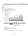
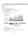
PARTS SUPPLIED
1 - Hood
%DIÀH¿OWHUV3 - AK7036BS and AK7042BS
+DORJHQOLJKWEXOEVpre-installed
6LQJOHLQWHUQDOEORZHUDQGEORZHUSODWHpre-installed
5HFWDQJXODUVWDUWLQJFROODUfor single blower horizontal ducting
1 - 8” round starting collar
5HFWDQJXODUPHWDOFDSfor single blower horizontal ducting
1 - Hardware package
HARDWARE PACKAGE CONTENTS
Light Bulb Removal
Suction Cup (1)
M6 x 2” (4)
M6 x 1-1/2” (4)
M6 x 1” (4)
M3.5 x 8 (4)
Wire Caps (3)
3/16 x 3/8 (4)
Washers (4)
PARTS NOT SUPPLIED
- Ducting, conduit and all installation tools
&DEOHFRQQHFWRUif required by local codes
'XDOEORZHUNLWPBD-1200AFRPSDWLEOHZLWK$.%6DQG$.%6RQO\
- Recirculating kit accessory *
*Recirculating kit only compatible with single internal blower, not with dual internal blower.
4
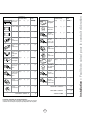
Equivalent number
length x used
=
Duct pieces
Total
Total
3-1/ 4” x 10” 1 Ft.
Rect.,
straight
x(
) =
Ft.
6” Round
30 Ft.
wall cap
with damper
x(
) =
Ft.
6” Round,
straight
1 Ft.
x(
) =
Ft.
6” Round,
roof cap
x(
) =
Ft.
7”-10” Round, 1 Ft.
x(
) =
Ft.
6” round to
1 Ft.
3-1/ 4” x 10”
rect.
transition
x(
) =
Ft.
3-1/ 4” x 10” 15 Ft.
Rect.90 0
elbow
x(
) =
Ft.
x(
) =
Ft.
3-1/ 4” x 10” 9 Ft.
Rect.45 0
elbow
x(
) =
Ft.
6” round to
16 Ft.
3-1/ 4” x 10”
rect.
transition
90 0 elbow
7” - 10”
Round,
90 0 elbow
15 Ft.
x(
) =
Ft.
3-1/ 4” x 10” 24 Ft.
Rect.90 0
flat elbow
x(
7” - 10”
Round,
45 0 elbow
9 Ft.
x(
) =
Ft.
3-1/ 4” x 10” 30 Ft.
Rect.
wall cap
with damper
x(
7” - 10”
30 Ft.
Round
wall cap
with damper
x(
) =
Ft.
3-1/ 4” x 10” 5 Ft.
Rect.to
6” round
transition
x(
) =
Ft.
7” - 10”
Round,
roof cap
x(
) =
Ft.
3-1/ 4” x 10” 20 Ft.
Rect.to
6” round
transition
90 0 elbow
x(
) =
Ft.
7” round to
8 Ft.
3 1/ 4” x 10”
rect.
transition
x(
) =
Ft.
) =
Ft.
15 Ft.
x(
) =
Ft.
7” round to
23 Ft.
3-1/ 4” x 10”
rect.
transition
90 0 elbow
x(
6” Round,
90 0 elbow
6” Round,
45 0 elbow
9 Ft.
x(
) =
Ft.
Subtotal column 2 =
Ft.
Subtotal column 1 =
Ft.
Total ductwork
Ft.
straight
) =
) =
Subtotal column 1 =
30 Ft.
Ft.
Ft.
Ft.
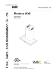
Maximum Duct Length: For satisfactory air movement,
the total duct length should not exceed 100 equivalent feet.
5
30 Ft.
=
Installation – Ducting Calculation Sheet
Equivalent number
length x used
=
Duct pieces
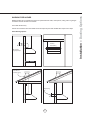
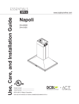
Installation – Mounting Height & Clearance
www.zephyronline.com
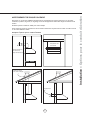
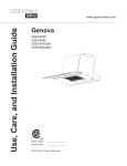
Minimum mount height between range top to hood
bottom should be no less than 26”.
Maximum mount height should be no higher than
36”.
It is important to install the hood at the proper
mounting height. Hoods mounted too low could
UHVXOWLQKHDWGDPDJHDQG¿UHKD]DUGZKLOH
hoods mounted too high will be hard to reach and
ZLOOORVHLWVSHUIRUPDQFHDQGHI¿FLHQF\
If available, also refer range manufacturer’s height
clearance requirements and recommended hood
mounting height above range.
in.
” m x.
6
2 ma
”
36
36”
Vertical Ducting:
´URXQGPLQLPXPVLQJHEORZHU
´URXQGPLQLPXPGXDOEORZHU
Horizontal Ducting:
´[´PLQLPXPVLQJOHEORZHU
´URXQGPLQLPXPVLQJOHEORZHU
No horizontal option available for dual blower
DUCTING
A minimum of 8” round or 3-1/4” x 10” rectangular
GXFWPXVWEHXVHGWRPDLQWDLQPD[LPXPDLUÀRZ
HI¿FLHQF\IRUVLQJOHEORZHUDQG´URXQGGXFWIRU
dual blower.
Always use rigid type metal ducts only. Flexible
GXFWVFRXOGUHVWULFWDLUÀRZE\XSWR
$OVRXVHFDOFXODWLRQRQSDJHWRFRPSXWHWRWDO
available duct run when using elbows, transitions
and caps.
ALWAYS, when possible, reduce the number or
transitions and turns. If long duct run is required,
increase duct size from 8” to 10”.
If turns or transitions are required; install as far
away from hood duct output and as far apart,
between the two as possible.
6
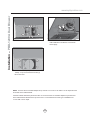
DAMAGE-SHIPMENT / INSTALLATION:
• Please fully inspect unit for damage before
installation.
• If the unit is damaged in shipment, return the
unit to the store in which it was bought for
repair or replacement.
• If the unit is damaged by the customer, repair
or replacement is the responsibility of the
customer.
,IWKHXQLWLVGDPDJHGE\WKHLQVWDOOHULIRWKHU
WKDQWKHFXVWRPHUUHSDLURIUHSODFHPHQW
must be made by arrangement between
customer and installer.
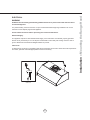
NEVER exhaust air or terminate duct work into spaces between walls, crawl spaces, ceiling, attics or garages.
All exhaust must be ducted to the outside.
Use metal ductwork only.
)DVWHQDOOFRQQHFWLRQVZLWKVKHHWPHWDOVFUHZVDQGWDSHDOOMRLQWVZLWKFHUWL¿HG6LOYHU7DSHRU'XFW7DSH
Some Ducting Options
Ductless
Recirculating
Side wall cap
w/ gravity damper
Roof Pitch w/
Flashing & Cap
Rear Ducting
7
Installation – Ducting Options
WARNING FIRE HAZARD
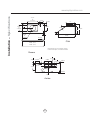
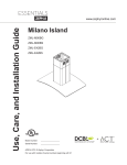
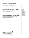
Installation – 6SHFL¿FDWLRQV
www.zephyronline.com
*9 1/2”
or
**14 3/16”
*8 1/8”
or
**10 3/8”
4 9/16”
12”
1 5/8”
6”
2”
8 9/16”
37˚
**15 5/16”
11”
3”
1”
*7 7/8”
or
**9 15/16”
22 1/2”
R 9/16”
side
29 7/8” (30”)
35 7/8” (36”)
41 7/8” (42”)
* Single Blower Dimension
** Dual Blower Dimension
top
11/16” 4 9/16”
7 3/8”
1 1/4”
9 7/8”
4 1/16”
4 9/16”
3 1/4”
2 3/16”
rect. C/L
round C/L
”
/8
77
2 3/16”
C/L
back
8
WARNING
$OO(OHFWULFDOZRUNPXVWE\SHUIRUPHGE\TXDOL¿HGHOHFWULFLDQRUSHUVRQZLWKVLPLODUWHFKQLFDONQRZ
how and background.
For personal safety, remove house fuse or open circuit breaker before beginning installation. Do not use
extension cord or adapter plug with this appliance.
Follow national electrical codes or prevailing local codes and ordinances.
Electrical Supply:
This appliance requires a 120V 60Hz electrical supply, and connected to an individual, properly grounded
branch circuit, protected by a 15 or 20 ampere circuit breaker or time delay fuse. Wiring must be 2 wire w/
ground. Please also refer Electrical Diagram labeled on product.
Cable Lock:
$FDEOHORFNLQJFRQQHFWRUQRWVXSSOLHGPLJKWDOVREHUHTXLUHGE\ORFDOFRGHV&KHFNZLWKORFDOUHTXLUHPHQWV
and codes, purchase and install appropriate connector if necessary.
Cable Lock
9
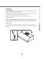
Installation – Mounting the Range Hood
ELECTRICAL
Installation – Mounting the Range Hood
www.zephyronline.com
For dual blower installation instructions please refer to
page 13.
If recirculating range hood refer to the manual
included with ZRC-07xxxB recirculating kit or on our
website prior to installing hood. Recirculating kit
compatible with 650cfm single internal blower only.
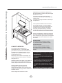
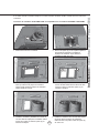
5. Duct
opening
cutout
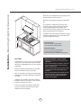
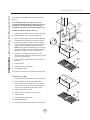
For Mounting Under a Kitchen Cabinet
6HOHFWSUHIHUUHGGXFWORFDWLRQYHUWLFDORUKRUL]RQWDO
duct/silver
tape
%HJLQLQVWDOODWLRQE\UHPRYLQJWKHEDIÀH¿OWHUV
3. Reinforce cabinet with 1”x2” wood strips if additional
strengthening is required or if cabinets are framed.
4. Temporarily position the range hood in the desired
mounting location. Measure and mark the mounting
holes, duct and electrical locations with a pencil.
NOTE: If using single internal blower a 8” round duct
opening is necessary. If using a dual internal blower,
please refer to page 14 for cut-out dimensions.
3. Add 1x2
wood strips
5. Drill/cut out the required openings for duct and
electrical access; make sure the duct opening is large
enough to apply duct tape.
)DVWHQKRRGRQWRFDELQHWZLWK0ZRRGVFUHZV
provided.
2. Baffle
filters
7. Install electrical.
8. Install duct work and duct tape.
5HLQVWDOOEDIÀH¿OWHUV
10. Power up hood and check for leaks around duct tape.
For Mounting to a Wall
6HOHFWSUHIHUUHGGXFWORFDWLRQYHUWLFDORUKRUL]RQWDO
%HJLQLQVWDOODWLRQE\UHPRYLQJWKHEDIÀH¿OWHUV
3. Temporarily position the range hood in the desired
mounting location. Measure and mark the mounting
holes, duct and electrical locations with a pencil.
4. Drill/cut out required openings.
2. Baffle
filters
5. Fasten hood onto wall with screws provided.
6. Install electrical.
7. Install duct work and duct tape.
5HLQVWDOOEDIÀH¿OWHUV
9. Power up hood and check for leaks around duct tape.
10
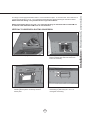
127(,IKRUL]RQWDOO\GXFWLQJYLD´[´UHFWDQJXODUGXFWLQJWKHPD[LPXPDLUÀRZRI&)0ZLOO
be reduced to 550 CFM. Other CFM levels will not be affected.
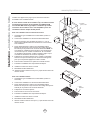
VERTICAL TO HORIZONTAL DUCTING CONVERSION
5HPRYHVFUHZVDWWRSRIKRRGERG\DWWDFKLQJ
blower to blower plate. Remove blower from
interior of hood body.
1. Disconnect blower plug.
A
B
5HPRYHVFUHZVIURPLQWHULRURIKRRGERG\
attaching blower plate to hood body. Remove
blower plate.
4. Knock out rear plates A & B for 8” round
rear ducting or plate B only for 3 1/4” x 10”
rectangular rear ducting.
11
Installation – Horizontal Conversion
This range hood is equipped standard with a 8” round vertical duct option. To convert from 8” round vertical to 8”
round horizontal ducting or 3-1/4” x 10” rectangular horizontal ducting please following the instructions below.
NOTE: Horizontal ducting is only available for the single internal blower.
Installation – Horizontal Conversion
www.zephyronline.com
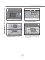
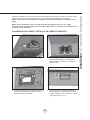
5. Place blower inside hood as shown.
6. Attach blower to hood body from the back of
KRRGXVLQJSUHYLRXVO\UHPRYHGEORZHU
screws and reconnect blower plug.
7. Attach 8” round duct collar or 3 1/4”x10”
rectangular duct collar to back of hood body
XVLQJ0[VFUHZV
8. From inside hood body, position top cover plate
to top of hood body. From outside hood body,
attach top cover plate to top of hood body using
[VFUHZV
12
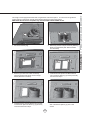
1. Disconnect blower plug.
5HPRYHVFUHZVDWWRSRIKRRGERG\DWWDFKLQJ
blower to single blower plate. Remove blower
from hood body.
5HPRYHVFUHZVIURPLQVLGHKRRGERG\
attaching single blower plate. Remove single
blower plate from hood body.
4. Install dual blower plate from PBD-1200A kit
LQWRKRRGERG\$WWDFKE\VFUHZVSUHYLRXVO\
removed from step 3.
6. Install blower from PBD-1200A kit onto other
VLGHRIGXDOEORZHUSODWHE\[
screws.
5. Install previously removed blower onto one side
RIGXDOEORZHUSODWHDQGDWWDFKE\SUHYLRXVO\
removed screws from step 2.
13
Installation – PBD-1200A Dual Blower
This range hood is equipped standard with a single blower vertical duct option. To convert from single blower
vertical ducting to dual blower vertical ducting please following the instructions below.
PBD-1200A dual blower kit compatible only with AK7036BS and AK7042BS models.
Installation – PBD-1200A Dual Blower
www.zephyronline.com
7. Dual Blower screw mount locations.
8. Connect blower wire extrension cable from
PBD-1200A kit to new blower. Connect both
blower plugs.
3ODFH´URXQGDGDSWHULQFOXGHGZLWK3%'
$RQWRSRIKRRGDQGVHFXUHZLWK
M3.5 x 8 screws.
NOTE: To secure the 10” transition adapter to top of hood a cut out of 14 1/2” width x 10 1/2” depth will need
to be made in the cabinet bottom.
If internal cabinet dimensions prevent this size of a cut out then the 10” transition adapter may be mounted
to the cabinet bottom rather than the top of the hood. Cut out dimensions for this type of installation are
13 1/4” width x 6 1/4” depth.
14
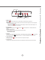
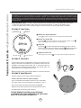
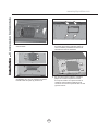
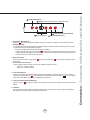
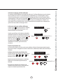
Display (speed level, delay off, filter clean)
Lights On/Dim/Off
Adjust 6 Speed Levels
5 Min Delay Off
1. Blower On/Off
By pressing
the blower is switched on and off. When switched on, the blower starts up on speed level 1.
ACT Verification
- Airflow Control Technology (ACT) allows the installer to set the maximum blower CFM to align with local codes and regulations.
- To verify the maximum blower CFM:
- With hood off, hold the
button for 3-4 seconds. If number 6 displays = default max. CFM, if number 3 displays = max.
390 CFM, and if number 2 displays = max. 290 CFM.
2. Speed Selection
The 6 speed levels are selected by pressing
to decrease and
to increase speed levels. The display indicates levels
selected.
ACT Enabled Speed Selections
- When ACT is enabled, the number of blower speeds will be reduced as follows:
- 390 CFM = Maximum 3 speeds
- 290 CFM = Maximum 2 speeds
3. Delay Off
This feature is used for programmed shut down of blower 5 minutes after the function is activated. Press
once, a dot flashes
in the lower right side of display
indicating the function is on. The blower will completely shut down after 5 minutes.
4. Lights On/Dim/Off
Switch lights on by pressing
once, press a second time to dim and again to shut off lights.
5. Display Window
The display window indicates speed levels and features such as baffle filter clean reminder, delay off and clean air indicator.
15
Features & Controls – Touch Controls & Features
Blower On/Off
Features & Controls – Touch Controls & Features
www.zephyronline.com
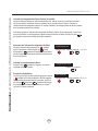
Charcoal Filter Change Reminder (charcoal filter, if installed)
When your hood is installed as a recirculating unit, it is fitted with a set of charcoal filters to purify exhaust
and fumes from cooking, then re-circulates the air within the home. These charcoal filters are required to
be replaced after every 120 hours of use. The charcoal filters should never be cleaned or placed in a dish
washer.
The filter change reminder function in the microprocessor needs to be switched on. When switched on, the
microprocessor will elapse and count usage time and indicate by a flashing C when charcoal filter
replacements are needed.
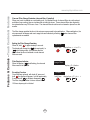
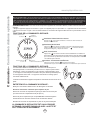
Setting the Filter Change Reminder
When off, hold
for approximately 5 seconds.
The display will change from
(exhaust mode) to
C (recirculating mode) this indicates that the
elapse timer function is switched on and charcoal
filters are used.
Filter Replace Indicator
When the display C starts flashing, the charcoal
filters need to be replaced.
Set Mode
hold 5 sec.
display from < - > to < C >
C
Set Mode
Change
FIlters
display < C > flashes
C
Re-setting Function
Once filters are replaced, with hood off, press and
hold
the display will appear; hold for apprimately
5 seconds until C on displays disappears
.
The filter change reminder is now re-set and a new
120 hour elapse cycle is initiated.
16
To Reset
hold 5 sec.
display from < C > to < >
C
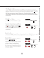
Baffle Filter Clean Indicator
When F flashes on the display, the baffle filters
needo be cleaned. This will occur after every 30
hours of use.
Clean Filters
display < F > flashes
F
Reset the filter clean reminder timer after filters are
cleaned and re-installed. With hood off, press and
hold
for approximately 5 seconds until F on
display disappears
. The filter clean reminder
function is now reset and a new 30 hours elapse
cycle is initiated.
To Reset
hold 5 sec.
display from < F > to < >
F
Clean Air Function
Clean Air is a feature that turns on the blower on low speed every 4 hours for 10 minutes to remove stagnant
air in the kitchen. The Clean Air function is disabled by default and must be enabled by the user.
Clean Air Indicator
While Clean Air is active, the display will alternate
between A , 1 , A , 1 .
To Enable
After 10 minutes of Clean Air operation, the blower
will power off and the 4 hour timer will reset.
hold 3 sec.
display < A > flashes
and
A
To Disable
hold 3 sec.
If the blower speed is changed while the Clean Air
Function is in use, the cycle will be interrupted and
the timer will reset after.
and
17
display from < A > to < >
A
Features & Controls – Touch Controls & Features
Baffle Filter Clean Reminder
Aa set of baffle filters are fitted by the factory, these baffle filters are intended to filter out residue from
cooking. The filters need not be replaced on a regular basis but are required to be kept clean. The BaffleFilter Clean reminder function in the microprocessor will automatically indicate by a flashing F when the
baffle filters need to be cleaned after every 30 hours of use. Filters can be cleaned by hand with nonabrasive soap or in a dishwasher. Heavily soiled filters should also be soaked in grease cutting detergent
prior to cleaning.
Features & Controls – Optional Remote Control
www.zephyronline.com
FCC Caution: To assure continued compliance, any changes or modifications not expressly approved by the party responsible for compliance could void the user’s authority to operate this equipment. (Example - use only shielded interface cables when connecting to computer
or peripheral device. This device complies with Part 15 of the FCC Rules. Operation is subject to the following two conditions. (1) This device
may not cause harmful interference, and (2) This device must accept any interference received, including interference that may cause
undesired operation.
SYNCHRONIZATION: To create a unique link between your hood and remote control please follow these steps:
1. With hood off, press and hold the “lights” button on the hood until the letter “F” shows on the display screen.
2. Press the “lights” button on the remote, the lights on the hood will turn on and synchronization is complete.
RF REMOTE FUNCTIONS:
Blower On/
Speed Selection 1
Blower On/
2 Power Off
1 Blower On / Speed Selection
Press
to power on blower and cycle through all six blower speeds.
2 Blower On / Power Off
By pressing
, the blowers will power on at the last speed setting. Press
again and the entire hood will power off, including lights.
3 Delay Off
By pressing
, the blower and lights will enter Delay Off mode. A dot will
appear in the lower right corner of the hood display
indicating the function
is on. The blower will change to speed 1 and shut down after 5 minutes.
4 Lights On / Dim / Off
5 Min Delay Off 3
4 Lights On/Dim/Off
Switch lights On by pressing
once, again to dim and again to switch Off.
RF REMOTE FEATURES:
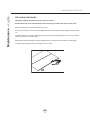
The RF remote control is equipped with a magnet on the back for easy
storage. The remote may be placed on any magnetic surface such as a
refrigerator or the Zephyr remote holder, FIG. 1. The remote holder can
be inserted into a standard electrical outlet for easy storage. Note: The
remote holder does not charge the RF remote.
Maximum remote control communication distance is 15 feet from the hood.
FIG. 1
RF REMOTE MAINTENANCE:
Clean the remote control using non abrasive detergents
Follow instructions below for replacing battery.
8VLQJDVPDOOÀDWKHDGVFUHZGULYHUUDLVHWKHFRYHURIWKHEDWWHU\
GRRUALQRUGHUWRDFFHVVWKHEDWWHU\FRPSDUWPHQW),*
Remove the battery and replace with battery type A23 12V.
Negative end of battery should face the spring inside the remote.
+
A
Re-install battery door and recycle old battery.
THE RF REMOVE CONTROL IS AN OPTIONAL
ACCESSORY NOT INCLUDED WITH THE HOOD AND
MUST BE PURCHASED SEPARATELY
18
FIG. 2
-
Clean periodically with hot soapy water and clean cotton cloth. Do not use corrosive or abrasive detergent,
or steel wool/scouring pads which will scratch and damage surface. Do not use products containing chlorine
bleach or orange cleaners.
For heavier soil use liquid degreaser.
After cleaning, you may use non-abrasive stainless steel polish/ cleaners, to polish and buff out the stainless
OXVWHUDQGJUDLQ$OZD\VVFUXEOLJKWO\XVLQJDPLFUR¿EHURUFOHDQFRWWRQFORWKDQGZLWKJUDLQ
6WDLQOHVV6WHHO%DIÀH)LOWHUV
7KHVWDLQOHVVVWHHOEDIÀH¿OWHUVDUHLQWHQGHGWRWUDSUHVLGXHDQGJUHDVHIURPFRRNLQJ$OWKRXJKWKH¿OWHUV
should never need replacing, they are required to be cleaned every 30 days or more often depending on
cooking habits.
)LOWHUVPD\EHSODFHGLQGLVKZDVKHUDWORZKHDWRUVRDNHGLQKRWVRDS\ZDWHU'U\¿OWHUVDQGUHLQVWDOOEHIRUH
using hood.
5HPRYLQJ%DIÀH)LOWHUV),*
3XVK¿OWHUWRZDUGEDFNRIUDQJHKRRGXVLQJKDQGOHV
3LYRWIURQWRI¿OWHUGRZQZDUG
5HPRYH¿OWHUE\SXOOLQJDZD\IURPKRRG
5HSODFLQJ%DIÀH)LOWHUV
Hood Model:
AK7000BS
AK7036BS
AK7042BS
Part No.
50210020
50210020
50210020
1
Qty. to Order.
2
3
3
2
Recirculating KitLQFOXGHVFKDUFRDO¿OWHUVDQGDLUGLYHUWHU
Hood Model:
AK7000BS
AK7036BS
AK7042BS
Part No.
ZRC-7000B
ZRC-7036B
ZRC-7042B
Qty. to Order.
1
1
1
Replacement Charcoal Filters also available by ordering
part number Z0F-C002.
3
See manual included with recirculating kit for more information.
FIG. 3
19
Maintenance – Cleaning , Filters and Recirculating
SURFACE MAINTENANCE:
Maintenance – Lights
www.zephyronline.com
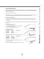
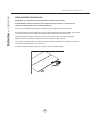
REPLACING LIGHT BULBS
CAUTION: Light bulb becomes extremely hot when turned on.
DO NOT touch bulb until switched off and cooled. Touching hot bulbs could cause serious burns.
Make sure all power is turned off and bulbs are not hot.
Remove by turning bulb counter clockwise. Note: Bulb does not unscrew; it turns 60 degrees, stops and falls
out.
,IEXOEVDUHGLI¿FXOWWRWXUQGXHWRSURORQJHGXVH¿UPO\DWWDFKWKHSURYLGHGJODVVVXFWLRQFXSRUXVHDUXEEHU
latex glove and turn counter clockwise.
5HSODFHPHQWEXOEVDUHDYDLODEOHDWVSHFLDOW\OLJKWLQJVWRUHV3XUFKDVHW\SH05*8:KDORJHQ
For Zephyr part numbers please turn to page 25 of the manual.
20
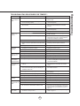
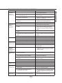
Issue
Cause
What to do
After installation,
the unit doesn’t
work.
1. The power source is not turned ON.
1. Make sure the circuit breaker and the unit’s
power is ON.
2. The power line and the cable locking connector
is not connecting properly.
2. Check the power connection with the unit is
connected properly.
3. The switch board and control board wirings are
disconnected.
3. Make sure the wirings between the switch
board and control board are connected
properly.
4. The wires on control board are loose.
4. Make sure the wires on the control board are
connected properly.
5. The switch board or control board is defective.
5. Change the switch board or control board.
1. The blower wire is not connected.
1. Make sure the blower wire is plugged into the
molex connector.
2. Blower molex plug pin is not making contact.
2. Disconnect the blower molex plug, check pins
inside plug to see if pin is pushed inside the
plug too far. Reseat pin if needed.
3. The blower is defective, possible seized.
3. Change the blower.
4. The thermally protected system detects if the
blower is too hot to operate and shuts the blower
down.
4. The blower will function properly after the
thermally protected system cool down.
5. Damaged capacitor.
5. Change the capacitor.
1. The blower is not secure in place.
1. Tighten the blower in place.
2. Damaged blower wheel.
2. Change the blower.
3. The hood is not secured in place.
3. Check the installation of the hood.
Lights work, but
blower is not
turning.
The unit is
vibrating.
The blower is
working, but the
lights are not.
1. The light bulb plug is disconnected.
1. Connect the light bulb plug.
2. Defective halogen bulb.
2. Change the halogen bulb.
3. The light bulb is loose.
3. Tighten the light bulb.
The speed levels
of the blower
sound the same.
1. Using the wrong size of ducting.
1. Change the ducting to at least 8” round or
3-1/4”x10” rectangular for single blower or 10”
round for dual blower.
The hood is
not venting out
properly.
1. The hood might be hanging to high from the
cook top.
1. Adjust the distance between the cook top and
the bottom of the hood within 26” and 36”
range.
2. The wind from the opened windows or opened
doors in the surrounding area are affecting the
ventilation of the hood.
2. Close all the windows and doors to eliminate
WKHRXWVLGHZLQGÀRZ
3. Blockage in the duct opening or duct work.
3. Remove all the blocking from the duct work or
duct opening.
4. The direction of duct opening is against the wind.
4. Adjust the duct opening direction.
5. Using the wrong size of ducting.
5. Change the ducting to correct size.
0HWDO¿OWHULV
vibrating.
0HWDO¿OWHULVORRVH
&KDQJHWKHPHWDO¿OWHU
2. Spring clip is broken.
2. Change the spring clip.
RF Remote
control does not
work.
1. Battery is dead.
1. Replace the battery with type A23 12v.
2. Poor communication with the hood.
2. Remote must be within 15 feet of the hood.
3. RF remote lost communication with the hood.
3. Reset the hood and remote by switching the
power off at the circuit breaker for 5 minutes.
Perform remote synchronization process on
page 18.
1. The clean air function has been enabled turning
the blower on every 4 hours.
1. Disable the clean air function by following the
steps on page 17.
The blower turns
on by itself.
21
Troubleshooting
TROUBLESHOOTING PROCEDURES FOR TEMPEST I
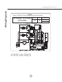
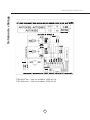
Wiring Diagrams
www.zephyronline.com
USE ONLY TYPE MR16, GU10, 35 W.
MAX.HALOGEN LIGHT BULBS.
AK7000BS, AK7036BS
AK7042BS
VOLTS
HZ
120
60
CIRCUIT DIAGRAM
ACT 390 CFM - Fan Max. 355W @ 2.8A
ACT 290 CFM - Fan Max. 255W @ 2.2A
22
MAX AMPS
5
Dual Motor 9
Single Motor
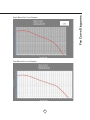
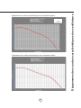
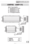
Fan Curve Diagrams
Single Blower Fan Curve Diagram
Dual Blower Fan Curve Diagram
23
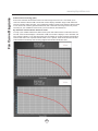
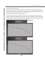
Fan Curve Diagrams
www.zephyronline.com
ALUÀRZ&RQWURO7HFKQRORJ\$&7
Some local codes limit the maximum amount of CFM a range hood can move. ACT allows you to
control the maximum blower CFM of hoods with of select Zephyr Ventilation range hoods without the
need for expensive make up air kits. ACT enables the installer to easily set the maximum blower speed
WRRQHRIWZRPRVWFRPPRQO\VSHFL¿HG&)0OHYHOVRU&)07KHXVDJHRI$&7PD\QRWEH
necessary for your installation. Please check your local codes for CFM restrictions.
By default the maximum blower CFM is set to 650.
To verify if your installer enabled ACT; With hood off, press and hold the blower on/off button for three
seconds. If the number 6 displays = defualt max. CFM, if the number 3 displays = max. 390 CFM, and
if the number 2 displays = max. 290 CFM. When ACT is enabled, the number of blower speeds will be
reduced. 390 CFM = max. 3 speeds and 290 CFM = max. 2 speeds. There should also be a foil label
located inside the hood body near the wiring diagram that indicates the blower CFM.
24
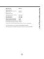
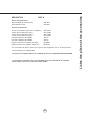
PART #
Replacement Parts
/LJKW%XOE05*8:HDFK
%DIÀH)LOWHUHDFK
=%
Optional Accessories
'XDO,QWHUQDO%ORZHU.LWZEORZHU
3%'$
5HFLUFXODWLQJ.LW´=5&%
5HFLUFXODWLQJ.LW´=5&%
5HFLUFXODWLQJ.LW´=5&%
%DFNVSODVKZ6KHOYHV$.%6
$.
%DFNVSODVKZ6KHOYHV$.%6
$.
%DFNVSODVKZ6KHOYHV$.%6
$.
Universal Make-Up Air Damper, 650 CFM
MUA008A
Universal Make-Up Air Damper, 1200 CFM MUA010A
To order parts, visit us online at http://store.zephyronline.com or call us at 1.888.880.8368
*Dual Internal Blower Kit only compatible with AK7036BS and AK7042BS
**Recirculating kit only compatible with single internal blower, not dual internal blower.
25
List of Parts and Accessories
DESCRIPTION
STAPLE YOUR RECEIPT HERE
Proof of the original purchase
date is needed to obtain
service under warranty
Limited Warranty
TO OBTAIN SERVICE UNDER WARRANTY OR FOR ANY SERVICE RELATED QUESTIONS, please call:
1-888-880-8368
Zephyr Corporation (referred to herein as “we” or “us”) warrants to the original consumer purchaser (referred to herein
as “you” or “your”) of Zephyr products (the “Products”) that such Products will be free from defects in materials or workmanship as follows:
Three Year Limited Warranty for Parts: For three years from the date of your original purchase of the Products, we
will provide, free of charge, Products or parts (including LED light bulbs, if applicable) to replace those that failed due to
manufacturing defects. We may choose, in our sole discretion, to repair or replace parts before we elect to replace the
Products.
One Year Limited Warranty for Labor: For one year from the date of your original purchase of the Products, we will
provide, free of charge, the labor cost associated with repairing the Products or parts to replace those that failed due to
manufacturing defects. After the first year from the date of your original purchase, you are responsible for all labor costs
associated with this warranty.
Warranty Exclusions: This warranty covers only repair or replacement, at our option, of defective Products or parts
and does not cover any other costs related to the Products including but not limited to: (a) normal maintenance and
service required for the Products and consumable parts such as incandescent or halogen light bulbs, metal and carbon
filters and fuses; (b) any Products or parts which have been subject to freight damage, misuse, negligence, accident,
faulty installation or installation contrary to recommended installation instructions, improper maintenance or repair (other
than by us); (c) commercial use of the Products or use otherwise inconsistent with its intended purpose; (d) natural wear
of the finish of the Products or wear caused by improper maintenance, use of corrosive and abrasive cleaning products,
pads, and oven cleaner products; (e) chips, dents or cracks caused by abuse or misuse of the Products; (f) service trips
to your home to teach you how to use the Products; or (g) damage to the Products caused by accident, fire, floods or act
of God. If you are outside our service area, additional charges may apply for shipping costs for warranty repair at our
designated service locations and for the travel cost to have a service technician come to your home to repair, remove or
reinstall the Products. After the first year from the date of your original purchase, you are also responsible for all labor
costs associated with this warranty.
Limitations of Warranty. OUR OBLIGATION TO REPAIR OR REPLACE, AT OUR OPTION, SHALL BE YOUR SOLE
AND EXCLUSIVE REMEDY UNDER THIS WARRANTY. WE SHALL NOT BE LIABLE FOR INCIDENTAL, CONSEQUENTIAL OR SPECIAL DAMAGES ARISING OUT OF OR IN CONNECTION WITH THE USE OR PERFORMANCE OF
THE PRODUCTS. THE EXPRESS WARRANTIES IN THE PRECEDING SECTION ARE EXCLUSIVE AND IN LIEU OF
ALL OTHER EXPRESS WARRANTIES. WE HEREBY DISCLAIM AND EXCLUDE ALL OTHER EXPRESS WARRANTIES FOR THE PRODUCTS, AND DISCLAIM AND EXCLUDE ALL WARRANTIES IMPLIED BY LAW, INCLUDING
THOSE OF MERCHANTABILITY AND FITNESS FOR A PARTICULAR PURPOSE. Some states or provinces do not
allow limitations on the duration of an implied warranty or the exclusion or limitation of incidental or consequential damages, so the above limitations or exclusions may not apply to you. To the extent that applicable law prohibits the exclusion of implied warranties, the duration of any applicable implied warranty is limited to the same two-year period
described above. Any oral or written description of the Products is for the sole purpose of identifying the Products and
shall not be construed as an express warranty. Prior to using, implementing or permitting use of the Products, you shall
determine the suitability of the Products for the intended use, and you shall assume all risk and liability whatsoever in
connection with such determination. We reserve the right to use functionally equivalent refurbished or reconditioned
parts or Products as warranty replacements or as part of warranty service. This warranty is not transferable from the
original purchaser and applies in the United States and Canada.
To Obtain Service Under Limited Warranty: To qualify for warranty service, you must: (a) notify us at the address or
telephone number stated below within 60 days of the discovery of the defect; (b) give the model number and part identification number and serial number; and (c) describe the nature of any defect in the Product or part. At the time of the
request for warranty service, you must present evidence of your proof of purchase and proof of the original purchase
date. If we determine that the warranty exclusions listed above apply or if you fail to provide the necessary documentation to obtain service, you will be responsible for all shipping, travel, labor and other costs related to the services.
Please check our website for any revisions, www.zephyronline.com.
MAY13.0301
Guide d’utilisation, d’entretien et d’installation
www.zephyronline.com
Tempest I
AK7000BS
AK7036BS
AK7042BS
Numéro de modèle :
Numéro de série :
Date d’achat :
Détaillant:
APR14.0301 © 2014 Zephyr Corporation
LISEZ ET CONSERVEZ CES INSTRUCTIONS
www.zephyronline.com
INSTALLATION
Feuille de calcul pour le conduit...................................................................................5
Espace libre et hauteur de montage...........................................................................6
Options d’installation pour le conduit..........................................................................7
6SpFL¿FDWLRQV........................................................................................................................8
Installation de la hotte........................................................................................................9-10
Conversion horizontale.....................................................................................................11-12
Ventilateur double PBD-1200A......................................................................................13-14
COMMANDES ET CARACTÉRISTIQUES
&RPPDQGHVjHIÀHXUHPHQWHWFDUDFWpULVWLTXHV .....................................................15-17
Commande à distance optionnelle ..............................................................................18
ENTRETIEN
1HWWR\DJHGHV¿OWUHVHWUHFLUFXODWLRQ.............................................................................19
Ampoules..................................................................................................................................20
DÉPANNAGE.............................................................................................................................................21
SCHÉMAS DE CÂBLAGE....................................................................................................................22
DIAGRAMMES DES COURBES CARACTÉRISTIQUESDES VENTILATEURS.........23-24
LISTES DES ACCESSOIRES ET DES PIÈCES.........................................................................25
1
Table des matières
MISE EN GARDE DE SÉCURITÉ..............................................................................2-3
LISTE DU MATÉRIEL...............................................................................................................4
www.zephyronline.com
Mise en garde de sécurité
LISEZ ET CONSERVEZ CES INSTRUCTIONS
AVERTISSEMENT
POUR RÉDUIRE LES RISQUES D’INCENDIE OU DE DÉCHARGE ÉLECTRIQUE, N’UTILISEZ PAS CET APPAREIL AVEC UN TABLEAU
DE COMMANDE À SEMI-CONDUCTEURS.
AVERTISSEMENT
POUR RÉDUIRE LES RISQUES D’INCENDIE, DE DÉCHARGE ÉLECTRIQUE OU DE BLESSURE, RESPECTEZ CES CONSIGNES :
D 1¶XWLOLVH]FHWDSSDUHLOTXHGHODPDQLqUHSUpYXHSDUOHIDEULFDQW6LYRXVDYH]GHVTXHVWLRQVFRPPXQLTXH]DYHFOHIDEULFDQW
E $YDQWGHSURFpGHUDXQHWWR\DJHRXjO¶HQWUHWLHQGHO¶DSSDUHLOpWHLJQH]O¶DOLPHQWDWLRQGXSDQQHDXpOHFWULTXHHWEORTXH]OHGLVSRVLWLIGH
GpFRQQH[LRQSRXUpYLWHUTXHO¶DOLPHQWDWLRQpOHFWULTXHQHVRLWDFFLGHQWHOOHPHQWUDOOXPpH6LOHGLVSRVLWLIGHVHFWLRQQHPHQWG¶pOHFWULFLWpQHSHXW
rWUHEORTXpDWWDFKH]XQDYHUWLVVHPHQWFRPPHXQHpWLTXHWWHELHQHQYXHVXUOHWDEOHDXpOHFWULTXH
ATTENTION
Pour ventilation générale seulement. N’utilisez pas cet appareil pour évacuer des vapeurs et des matériaux explosifs ou dangereux. Prenez garde
ORUVGHO¶XWLOLVDWLRQG¶DJHQWVQHWWR\DQWVRXGHGpWHUJHQWV1HGHYUDLWrWUHXWLOLVpTXHGDQVODFXLVLQHGHYRWUHPDLVRQ
AVERTISSEMENT
POUR RÉDUIRE LES RISQUES DE FEU DE GRAISSE SUR LA SURFACE DE CUISSON :
a. Ne laissez jamais l’appareil sans surveillance lors de son utilisation à haute température. Les débordements par bouillonnement causent de la
IXPpHHWGHVGpYHUVHPHQWVGHJUDLVVHTXLSHXYHQWSUHQGUHIHX)DLWHVFKDXIIHUO¶KXLOHjGHVWHPSpUDWXUHVEDVVHVRXPR\HQQHV
E $OOXPH]WRXMRXUVODKRWWHORUVTXHYRXVFXLVLQH]jKDXWHWHPSpUDWXUHRXTXHYRXVIDLWHVÀDPEHUGHVDOLPHQWV
F 1HWWR\H]IUpTXHPPHQWOHVYHQWLODWHXUVGHODKRWWH/DJUDLVVHQHGHYUDLWMDPDLVV¶DFFXPXOHUGDQVOHVYHQWLODWHXUVRXOHV¿OWUHV
G 8WLOLVH]GHVSRrORQVDX[GLPHQVLRQVDGpTXDWHV8WLOLVH]WRXMRXUVXQHEDWWHULHGHFXLVLQHFRUUHVSRQGDQWDX[GLPHQVLRQVGHO¶pOpPHQW
H $VVXUH]YRXVTXHOHYHQWLODWHXUOHV¿OWUHVHWOHVVXUIDFHVRODJUDLVVHSRXUUDLWV¶DFFXPXOHUVRQWWRXMRXUVSURSUHV
I 8WLOLVH]OHUpJODJHKDXWGHODKRWWHVHXOHPHQWORUVTXHQpFHVVDLUH
J 1HODLVVH]SDVODKRWWHVDQVVXUYHLOODQFHORUVTXHYRXVFXLVLQH]
K 8WLOLVH]WRXMRXUVXQHEDWWHULHGHFXLVLQHHWGHVXVWHQVLOHVFRQYHQDQWDXW\SHHWjODTXDQWLWpGHQRXUULWXUHTXHYRXVSUpSDUH]
AVERTISSEMENT
POUR RÉDUIRE LES RISQUES DE BLESSURE LORS D’UN INCENDIE SUR LA SURFACE DE CUISSON :
D e728))(=/(6)/$00(6DYHFXQFRXYHUFOHXQHSODTXHjELVFXLWVRXXQSODWHDXGHPpWDOHWpWHLJQH]HQVXLWHOHEUOHXU35(1(=*$5'(
$8;5,648(6'(%5Ó/85(6LOHVÀDPPHVQHGLVSDUDLVVHQWSDVe9$&8(=/(6/,(8;(7$33(/(=/(6(59,&('¶,1&(1',(
E 1(35(1(=-$0$,68132Ç/21(1)(8±9RXVSRXUULH]YRXVEUOHU
c. N’UTILISEZ PAS D’EAU, ou un linge à vaisselle mouillé – une violente explosion de vapeur s’ensuivra.
d. Utilisez un extincteur SEULEMENT si :
9RXVVDYH]TXHYRXVSRVVpGH]XQH[WLQFWHXUGHFODVVH$%&HWYRXVVDYH]YRXVHQVHUYLU
2. Le feu est faible et ne s’est pas répandu depuis son point d’origine.
3. Vous avez appelé le service d’incendie.
9RXVSRXYH]VRUWLUIDFLOHPHQWGHO¶HQGURLWRYRXVFRPEDWWH]OHIHX
AVERTISSEMENT
POUR RÉDUIRE LES RISQUES D’INCENDIE, DE DÉCHARGE ÉLECTRIQUE OU DE BLESSURE, SUIVEZ LES CONSIGNES SUIVANTES :
D /HVWUDYDX[G¶LQVWDOODWLRQHWGHFkEODJHpOHFWULTXHGRLYHQWrWUHIDLWVSDUXQHSHUVRQQHTXDOL¿pHVHORQOHVVWLSXODWLRQVGHWRXVOHVQRUPHVHW
standards en vigueur, dont les normes des constructions ayant une cote de résistance au feu.
E 3RXUSUpYHQLUOHVFRQWUHH[SORVLRQVXQHFHUWDLQHTXDQWLWpG¶DLUHVWQpFHVVDLUHSRXUODFRPEXVWLRQHWO¶pYDFXDWLRQGHVJD]SDUOHFDUQHDX
FKHPLQpHGHO¶DSSDUHLOGHFRPEXVWLRQ5HVSHFWH]OHVGLUHFWLYHVGXIDEULFDQWG¶RXWLOODJHGHFKDXIIDJHHWOHVQRUPHVGHVpFXULWpFRPPHFHOOHV
SXEOLpHVSDUOD1)3$$VVRFLDWLRQQDWLRQDOHGHVVHUYLFHVG¶LQFHQGLHSDUOD6RFLpWpDPpULFDLQHGHVLQJpQLHXUVHQFKDXIIDJHUpIULJpUDWLRQHW
FOLPDWLVDWLRQ$6+5$(HWSDUOHVQRUPHVGHVDXWRULWpVORFDOHV
F /RUVTXHYRXVFRXSH]RXSHUFH]XQPXURXXQSODIRQGDVVXUH]YRXVGHQHSDVHQGRPPDJHUOHFkEODJHpOHFWULTXHRXWRXWHDXWUHLQVWDOODWLRQ
WHFKQLTXHGLVVLPXOpH
d. Les ventilateurs canalisés doivent toujours évacuer l’air à l’extérieur.
e. N’installez JAMAIS un interrupteur à une distance atteignable depuis un bain ou une douche.
I $VVXUH]YRXVTXHO¶DOLPHQWDWLRQpOHFWULTXHHVWpWHLQWHDYDQWGHSURFpGHUjO¶LQVWDOODWLRQDXFkEODJHRXjO¶HQWUHWLHQGHO¶DSSDUHLO.
2
POUR RÉDUIRE LES RISQUES D’INCENDIE, N’UTILISEZ QUE DES CONDUITS D’AÉRATION EN MÉTAL.
ATTENTION
3RXUUpGXLUHOHVULVTXHVG¶LQFHQGLHHWSRXUpYDFXHUO¶DLUFRQYHQDEOHPHQWDVVXUH]YRXVGHFDQDOLVHUO¶DLUjO¶H[WpULHXUGH
la maison. N’installez pas l’échappement du conduit dans les espaces entre les murs, le plafond, le grenier, les vides
sanitaires ou le garage.
Cet appareil n’est pas conçu pour être utilisé à l’extérieur.
FONCTIONNEMENT
/DLVVH]WRXMRXUVOHVJULOOHVGHVUHWpHWOHV¿OWUHVHQSODFH6DQVFHVpOpPHQWVOHVYHQWLODWHXUVHQPDUFKHSRXUUDLHQW
accrocher des cheveux, des doigts ou des vêtements amples.
Le fabricant se dégage de toute responsabilité dans les cas de non-respect des instructions transmises dans le présent
PDQXHOSRXUO¶LQVWDOODWLRQO¶HQWUHWLHQHWO¶XWLOLVDWLRQDGpTXDWHGXSURGXLW/HIDEULFDQWVHGpJDJHpJDOHPHQWGHWRXWH
UHVSRQVDELOLWpSRXUGHVEOHVVXUHVTXLUpVXOWHUDLHQWGHODQpJOLJHQFHORUVGHO¶XWLOLVDWLRQ'HSOXVODJDUDQWLHSUHQG¿Q
DXWRPDWLTXHPHQWORUVGHO¶HQWUHWLHQLQDSSURSULpGHO¶DSSDUHLO
*NOTE : Veuillez communiquer avec nous ou visitez le www.zephyronline.com pour obtenir des révisions avant
de procéder à des travaux sur commande.
EXIGENCES ÉLECTRIQUES
Important :
5HVSHFWH]WRXVOHVFRGHVHWUqJOHPHQWVHQYLJXHXU
Il est de la responsabilité du client de :
&RPPXQLTXHUDYHFXQLQVWDOODWHXUpOHFWULFLHQTXDOL¿p
6¶DVVXUHUTXHO¶LQVWDOODWLRQpOHFWULTXHHVWDGpTXDWHHWTX¶HOOHUHVSHFWHOH&RGHQDWLRQDOGHO¶pOHFWULFLWpODSOXVUpFHQWH
édition* du ANSI/NFPA 70 ou des normes du CSA C22.1-94, le Code canadien de l’électricité, section 1, la plus récente
pGLWLRQGXFRGH&1R0DLQVLTXHWRXVOHVFRGHVHWUpJOHPHQWVHQYLJXHXU
6LOHVFRGHVSHUPHWWHQWO¶XWLOLVDWLRQG¶XQ¿OGHJDUGHLVROpHWTXHYRXVHQXWLOLVH]XQLOHVWUHFRPPDQGpTX¶XQpOHFWULFLHQ
TXDOL¿pGpWHUPLQHVLOHFKHPLQHPHQWGX¿OHVWDGpTXDW
N’effectuez pas la mise à la terre à un tuyau de gaz.
'HPDQGH]jXQpOHFWULFLHQTXDOL¿pVLYRXVQ¶rWHVSDVFHUWDLQTXHODKRWWHDpWpPLVHjODWHUUHDGpTXDWHPHQW
N’introduisez aucun fusible dans le circuit neutre ou de mise à la terre.
*National Fire Protection Association Batterymarch Park, Quincy, Massachusetts 02269
** CSA International 8501 East Pleasant Valley Road, Cleveland, Ohio 44131-5575
&HWDSSDUHLOUHTXLHUWXQHDOLPHQWDWLRQpOHFWULTXHGH9+],OGRLWrWUHFRQQHFWpjXQFLUFXLWWHUPLQDOLQGLYLGXHO
GPHQWPLVjODWHUUHSURWpJpSDUXQGLVMRQFWHXUGHFLUFXLWRXXQIXVLEOHWHPSRULVpGHRXDPSqUHV/HFkEODJHGRLW
FRPSWHU¿OVDYHFPLVHjODWHUUH9HXLOOH]YRXVUpIpUHUDX'LDJUDPPHpOHFWULTXHpWLTXHWpVXUO¶DSSDUHLO
8QUDFFRUGGHFkEOHQRQLQFOXVSRXUUDLWpJDOHPHQWrWUHH[LJpSDUOHVQRUPHVHWUpJOHPHQWDWLRQVORFDOHV,QIRUPH]YRXV
des exigences et des normes locales. Achetez et installez le connecteur approprié si nécessaire.
3
Mise en garde de sécurité
ATTENTION
Liste du matériel
www.zephyronline.com
MODÈLES : AK7000BS, AK7036BS, AK7042BS
PIÈCES FOURNIES
1 - Hotte
)LOWUHVGpÀHFWHXUV3 - AK7036BS et AK7042BS
$PSRXOHVKDORJqQHVpréinstallées
9HQWLODWHXULQWHUQHVLPSOHHWSODTXHGXYHQWLODWHXUpréinstallés
&ROOLHUGHGpSDUWUHFWDQJXODLUHpour conduit horizontal avec ventilateur simple
1 - Collier de départ circulaire de 8”
&RXYHUFOHUHFWDQJXODLUHPpWDOOLTXHpour conduit horizontal avec ventilateur simple
7URXVVHGHTXLQFDLOOHULH
CONTENU DE LA TROUSSE DE QUINCAILLERIE
(1) Ventouse pour
enlever des ampoules
(4) M6 x 2”
(4) M6 x 1-1/2”
(4) M6 x 1”
(4) M3.5 x 8
(3) Capuchons de
connexion
(4) 3/16 x 3/8
(4) Rondelles
PIÈCES NON FOURNIES
- Conduit et tous les outils d’installation
5DFFRUGGHFkEOHVLH[LJpSDUOHVFRGHVHQYLJXHXU
7URXVVHGHYHQWLODWHXUGRXEOH3%'$FRPSDWLEOHDYHFOHVPRGqOHV$.%6HW$.%6VHXOHPHQW
- Trousse de recirculation d’air*
*La trousse de recirculation d’air n’est compatible qu’avec les ventilateurs internes simples, et pas avec les
ventilateurs internes doubles.
4
pi
3-1/ 4” x 10” 1 pi
rect., droit
x(
6” circ., droit 1 pi
x(
) =
pi
7” circ., droit 1 pi
x(
) =
pi
3-1/ 4” x 10” 15 pi
rect.,
coude à 90º
x(
) =
pi
3-1/ 4” x 10” 9 pi
rect.,
coude à 45º
x(
) =
pi
3-1/ 4” x 10” 24 pi
rect.,
coude plat
à 90º
x(
3-1/ 4” x 10” 30 pi
x(
) =
Longueur x
Nombre utilisé
Pièces de conduit
Total
Total
30 pi
x(
) =
pi
6”
chapeau de
toiture circ.
30 pi
x(
) =
pi
6” circ. à
rect. de
3-1/4" x 10"
1 pi
x(
) =
pi
6” circ. à
16 pi
rect. de
3-1/4" x 10",
coude à 90º
x(
) =
pi
7” or 10”
15 pi
circ.,
coude à 90º
x(
) =
pi
7” or 10”
9 pi
circ.,
coude à 45º
x(
) =
pi
7” or 10”
30 pi
embout
mural
circ./registre
x(
) =
pi
7” or 10”
30 pi
x(
) =
pi
8 pi
x(
) =
pi
x(
) =
pi
6”
embout mural
circ./registre
) =
) =
pi
pi
embout mural
rect./registre
pi
3-1/ 4” x 10” 5 pi
rect. à circ.
de 6"
x(
3-1/ 4” x 10” 20 pi
coude à 90º
rect. à circ.
de 6"
x(
) =
pi
6” circ.,
15 pi
coude à 90º
x(
) =
pi
6” circ.,
9 pi
coude à 45º
x(
) =
pi
) =
circ., chapeau
de toiture
Sous-total - colonne 1=
7” circ. à
rect. de
3-1/4" x 10"
7” circ. à
23 pi
rect. de
3-1/4" x 10",
coude à 90º
pi
Longueur maximale du conduit d’aération :
Pour un mouvement d’air convenable, la longueur totale d’un conduit
d’aération ne devrait pas compter plus que l’équivalent de 100 pieds.
5
Sous-total - colonne 2
=
pi
Sous-total - colonne 1
=
pi
Total du conduit
=
pi
Installation – Feuille de calcul pour le conduit d’aération
Longueur x
Nombre utilisé
Pièces de conduit
Installation – Espace libre et hauteur de montage
www.zephyronline.com
adaptateurs sont nécessaires, installez-les le
plus loin possible de l’ouverture et le plus éloigné
possible l’un de l’autre.
La hauteur de montage de la surface de la
FXLVLQLqUHDXEDVGHODKRWWHQHGHYUDLWSDVrWUH
inférieure à 26”.
La hauteur de montage maximale ne devrait pas
outrepasser 36”.
Il est important d’installer la hotte à la hauteur
GHPRQWDJHDGpTXDWH/HVKRWWHVLQVWDOOpHV
trop basses pourraient être endommagées par
ODFKDOHXUHQSOXVGHSUpVHQWHUGHVULVTXHV
G¶LQFHQGLHSOXVpOHYpVWDQGLVTXHOHVKRWWHV
LQVWDOOpHVWURSKDXWHVVHURQWGLI¿FLOHVjDWWHLQGUH
HWYHUURQWOHXUHI¿FDFLWpHWOHXUUHQGHPHQWUpGXLWV
n.
mi .
”
26 max
”
36
36”
Si elles sont disponibles, consultez les exigences
GHKDXWHXUG¶HVSDFHOLEUHUHTXLVHSDUOHIDEULFDQW
GHODFXLVLQLqUHDLQVLTXHODKDXWHXUUHFRPPDQGpH
de montage de la hotte au-dessus de la surface
de cuisson.
Conduit vertical :
´FLUFXODLUHPLQLPXPYHQWLODWHXUVLPSOH
´FLUFXODLUHPLQLPXPYHQWLODWHXUGRXEOH
Conduit horizontal :
´[´PLQLPXPYHQWLODWHXUVLPSOH
´FLUFXODLUHPLQLPXPYHQWLODWHXUVLPSOH
Pas d’option horizontale avec les ventilateurs
doubles
CONDUIT D’AÉRATION
Un conduit circulaire minimal de 8” ou
rectangulaire de 3-1/4” x 10” doit être utilisé
pour assurer un mouvement d’air maximale lors
de l’utilisation d’un ventilateur simple. Lors de
l’utilisation d’un ventilateur double, le conduit
circulaire doit être de 10”.
1¶XWLOLVH]TXHGHVFRQGXLWVHQPpWDOULJLGH/HV
conduits souples pourraient réduire la circulation
G¶DLUMXVTX¶j
8WLOLVH]ODIHXLOOHGHFDOFXOSDJHSRXUREWHQLUOD
longueur totale du conduit lors de l’utilisation de
FRXGHVGHSLqFHVGHWUDQVLWLRQRXGHFRXYHUFOHV
/RUVTX¶LOSRVVLEOHGHOHIDLUHGLPLQXH]
728-2856OHQRPEUHGHSLqFHVHWGH
changements de direction. Si un long tronçon de
FRQGXLWHVWQpFHVVDLUHDXJPHQWH]OHGLDPqWUHGX
conduit de 8” à 10”.
Si des changements de direction ou des
6
ENDOMMAGEMENT LORS DE LA LIVRAISON/
INSTALLATION :
9HXLOOH]YRXVDVVXUHUTXHWRXWHVOHVSLqFHV
de l’appareil ne sont pas endommagées avant
l’installation.
• Si l’appareil est endommagé durant la livraison,
UHWRXUQH]O¶DSSDUHLOjO¶HQGURLWRYRXVO¶DYH]
acheté pour réparation ou remplacement.
• Si l’appareil est endommagé par le client, la
réparation ou le remplacement est à la charge du
client.
• Si l’appareil est endommagé par l’installateur
VLDXWUHTXHOHFOLHQWOHFOLHQWHWO¶LQVWDOODWHXU
doivent en venir à une entente pour la réparation
N’évacuez ou ne terminez JAMAIS l’échappement du conduit dans les espaces entre les murs, les vides
sanitaires, le plafond, le grenier, ou le garage. Tous les échappements doivent être dirigés à l’extérieur de la
maison.
1¶XWLOLVH]TXHGHVFRQGXLWVHQPpWDOSRXUFORLVRQVLPSOH
)L[H]WRXWHVOHVSLqFHVGXFRQGXLWDYHFGHVYLVjW{OHHWLVROH]WRXVOHVMRLQWVDYHFGXUXEDQjFRQGXLWHQWRLOH
RXGXUXEDQUpÀHFWHXUFHUWL¿p
Exemples d’options pour le conduit d’aération
Récupération d’air
sans conduit
Bouche d’aération de
mur latéral avec
clapet antirefoulement
Pente de la toiture
avec solin et chapeau
Conduit arrière
7
Installation – Options pour le conduit d’aération
AVERTISSEMENT DE RISQUE D’INCENDIE
Installation – 6SpFL¿FDWLRQV
www.zephyronline.com
*9 1/2”
ou
**14 3/16”
*8 1/8”
or
**10 3/8”
4 9/16”
12”
1 5/8”
6”
2”
8 9/16”
37˚
**15 5/16”
11”
3”
1”
*7 7/8”
or
**9 15/16”
22 1/2”
R 9/16”
Côté
29 7/8” (30”)
35 7/8” (36”)
41 7/8” (42”)
* Dimensions pour le ventilateur simple
** Dimensions pour le ventilateur double
Dessus
11/16” 4 9/16”
7 3/8”
1 1/4”
9 7/8”
4 1/16”
4 9/16”
3 1/4”
2 3/16”
L/C rect.
L/C circ.
”
/8
77
2 3/16”
L/C
Arrière
8
AVERTISSEMENT
7RXVOHVWUDYDX[pOHFWULTXHVGRLYHQWrWUHUpDOLVpVSDUXQpOHFWULFLHQTXDOL¿pRXXQHSHUVRQQHDYHF
l’expérience technique et le savoir-faire nécessaires.
Pour votre sécurité, enlevez le fusible ou éteignez le disjoncteur de circuit avant de commencer l’installation.
1¶XWLOLVH]SDVGHUDOORQJHpOHFWULTXHRXG¶DGDSWDWHXUDYHFFHWpOHFWURPpQDJHU
Suivez le code électrique national ou les codes et réglementations en vigueur.
Alimentation électrique :
&HWDSSDUHLOUHTXLHUWXQHDOLPHQWDWLRQpOHFWULTXHGH9+]HWGRLWrWUHFRQQHFWpjXQFLUFXLWWHUPLQDO
LQGLYLGXHOGPHQWPLVjODWHUUHHWSURWpJpSDUXQGLVMRQFWHXUGHFLUFXLWRXXQIXVLEOHWHPSRULVpGHRX
DPSqUHV/HFkEODJHGRLWFRPSWHUGHX[¿OVDYHFPLVHjODWHUUH9HXLOOH]FRQVXOWHUOHVFKpPDGHFkEODJH
pWLTXHWpVXUO¶DSSDUHLO
Raccord de câble :
/HVQRUPHVHWUpJOHPHQWDWLRQVORFDOHVSHXYHQWpJDOHPHQWH[LJHUO¶XWLOLVDWLRQG¶XQUDFFRUGGHFkEOHQRQ
LQFOXV,QIRUPH]YRXVGHVH[LJHQFHVHWGHVQRUPHVORFDOHV$FKHWH]HWLQVWDOOH]OHFRQQHFWHXUDSSURSULpVL
nécessaire.
Raccord de câble
9
Installation – Installation de la hotte
ÉLECTRICITÉ
Installation – Installation de la hotte
www.zephyronline.com
Veuillez vous rapporter à la page 13 pour obtenir les instruction
d’installation d’un ventilateur double.
Si vous utilisez le mode de recirculation d’air, consultez le manuel
accompagnant la trousse de récupération d’air ZRC-07xxxB
ou notre site Web avant de procéder à l’installation de la hotte.
La trousse de recirculation d’air n’est compatible qu’avec les
ventilateurs internes simples de 650 pi3/min.
5. Ouverture
pour le conduit
ruban à
conduit
Pour une installation sous une armoire de cuisine
&KRLVLVVH]OHW\SHG¶LQVWDOODWLRQGHFRQGXLWGpVLUpYHUWLFDORX
KRUL]RQWDO
&RPPHQFH]O¶LQVWDOODWLRQHQHQOHYDQWOHV¿OWUHVGpÀHFWHXUV
3. Renforcez l’armoire avec des lattes de bois de 1” x 2” si du
renforcement supplémentaire est nécessaire ou si les armoires
sont encadrées.
3. Ajoutez deux
lattes de bois
de 1 x 2
4. Placez temporairement la hotte au lieu d’installation désiré.
0HVXUH]HWPDUTXH]DXFUD\RQOHVWURXVGHPRQWDJHDLQVLTXH
OHVHQGURLWVSDURSDVVHURQWOHFRQGXLWHWO¶pOHFWULFLWpNOTE : Si
YRXVXWLOLVH]XQYHQWLODWHXULQWHUQHVLPSOHLOYRXVIDXWSUDWLTXHU
une ouverture pour un conduit circulaire de 8”. Si vous utilisez
un ventilateur interne double, veuillez consulter la page 14 pour
FRQQDvWUHOHVGLPHQVLRQVGHO¶RXYHUWXUHjSUDWLTXHU
3UDWLTXH]OHVRXYHUWXUHVUHTXLVHVSRXUOHFRQGXLWHWO¶pOHFWULFLWp
$VVXUH]YRXVTXHO¶RXYHUWXUHSRXUOHFRQGXLWHVWDVVH]JUDQGH
SRXUTXHYRXVSXLVVLH]DSSOLTXHUGXUXEDQjFRQGXLW
2. Filtres
déflecteurs
)L[H]ODKRWWHjO¶DUPRLUHDYHFTXDWUHYLVjERLV0IRXUQLHV
3URFpGH]jO¶LQVWDOODWLRQGHVFRPSRVDQWHVpOHFWULTXHV
8. Installez le conduit et le ruban à conduit.
5pLQVWDOOH]OHV¿OWUHVGpÀHFWHXUV
$OOXPH]ODKRWWHHWDVVXUH]YRXVTX¶LOQ¶\DSDVGHIXLWHVDXWRXUGX
ruban à conduit.
Pour une installation murale
&KRLVLVVH]OHW\SHG¶LQVWDOODWLRQGHFRQGXLWGpVLUpYHUWLFDORX
KRUL]RQWDO
&RPPHQFH]O¶LQVWDOODWLRQHQHQOHYDQWOHV¿OWUHVGpÀHFWHXUV
3. Placez temporairement la hotte au lieu d’installation désiré.
0HVXUH]HWPDUTXH]DXFUD\RQOHVWURXVGHPRQWDJHDLQVLTXHOHV
HQGURLWVSDURSDVVHURQWOHFRQGXLWHWO¶pOHFWULFLWp
3UDWLTXH]OHVRXYHUWXUHVUHTXLVHV
5. Fixez la hotte au mur avec les vis fournies.
3URFpGH]jO¶LQVWDOODWLRQGHVFRPSRVDQWHVpOHFWULTXHV
7. Installez le conduit et le ruban à conduit.
5pLQVWDOOH]OHV¿OWUHVGpÀHFWHXUV
$OOXPH]ODKRWWHHWDVVXUH]YRXVTX¶LOQ¶\DSDVGHIXLWHVDXWRXUGX
ruban à conduit.
10
2. Filtres
déflecteurs
NOTE : Si vous souhaitez installer un conduit horizontal rectangulaire de 3-1/4” x 10”, le débit
d’évacuation d’air maximal de 650 pi3/min sera réduit à 550 pi3/min. Il n’y aura pas de conséquences sur
les autres niveaux de pi3/min.
CONVERSION D’UN CONDUIT VERTICAL À UN CONDUIT HORIZONTAL
(QOHYH]OHVTXDWUHYLVGHODSDUWLHVXSpULHXUH
GHODKRWWHTXLUHWLHQQHQWOHYHQWLODWHXUjOD
SODTXH5HWLUH]OHYHQWLODWHXUGHO¶LQWpULHXUGX
bâti de la hotte.
'pEUDQFKH]OD¿FKHGXYHQWLODWHXU
A
B
(QOHYH]OHVTXDWUHYLVGHO¶LQWpULHXUGHODKRWWH
TXLUHWLHQQHQWODSODTXHGXYHQWLODWHXUDXEkWL
5HWLUH]ODSODTXHGXYHQWLODWHXU
(QOHYH]OHVSODTXHVGpIRQoDEOHVDUULqUH$HW
%SRXULQVWDOOHUXQFRQGXLWFLUFXODLUHDUULqUHRX
VHXOHPHQWODSODTXH%SRXULQVWDOOHUXQFRQGXLW
rectangulaire de 3-1/4” x 10”.
11
Installation – Conversion horizontale
Cette hotte standard est munie d’une entrée pour conduit vertical circulaire de 8”. Pour la convertir à un conduit
horizontal circulaire de 8” ou rectangulaire 3-1/4” x 10”, veuillez suivre les instructions ci-dessous.
NOTE : L’option du conduit horizontal n’est disponible que lors de l’utilisation d’un ventilateur interne
simple.
Installation – Conversion horizontale
www.zephyronline.com
5. Placez le ventilateur à l’intérieur de la hotte,
comme illustré.
6. Fixez le ventilateur au bâti de la hotte à partir
GHO¶DUULqUHGHODKRWWHjO¶DLGHGHVTXDWUH
vis de ventilateur préalablement enlevées et
UHEUDQFKH]OD¿FKHGXYHQWLODWHXU
7. Fixez le collier de conduit circulaire de 8” ou
UHFWDQJXODLUHGH´[´jO¶DUULqUHGXEkWLGH
ODKRWWHjO¶DLGHGHTXDWUHYLV0[
8. De corps de la hotte à l’intérieur, la position
SODTXHGHFRXYHUWXUHVXSpULHXUHHQKDXW
du corps de la hotte. De corps de la hotte à
O¶H[WpULHXU¿[H]ODSODTXHVXSpULHXUHGHOD
couverture en haut du corps de la hotte à l’aide
[YLV
12
La trousse du ventilateur double PBD-1200A est compatible avec les modèles AK7036BS et AK7042BS.
'pEUDQFKH]OD¿FKHGXYHQWLODWHXU
(QOHYH]OHVTXDWUHYLVGHODSDUWLHVXSpULHXUH
GHODKRWWHTXLUHWLHQQHQWOHYHQWLODWHXUj
ODSODTXHGXYHQWLODWHXUVLPSOH5HWLUH]OH
ventilateur du bâti de la hotte.
(QOHYH]OHVTXDWUHYLVGHO¶LQWpULHXUGHOD
KRWWHTXLUHWLHQQHQWODSODTXHGXYHQWLODWHXU
VLPSOHDXEkWL5HWLUH]ODSODTXHGXYHQWLODWHXU
simple du bâti de la hotte.
,QVWDOOH]ODSODTXHGXYHQWLODWHXUGRXEOHGHOD
trousse du PBD-1200A dans le bâti de la hotte.
)L[H]ODHQSODFHjO¶DLGHGHVTXDWUHYLV
enlevées à l’étape 3.
5. Installez le ventilateur préalablement enlevé de
O¶XQGHVF{WpVGHODSODTXHGXYHQWLODWHXUGRXEOH
HW¿[H]OHHQSODFHjO¶DLGHGHVTXDWUHYLV
13
enlevées à l’étape 2.
6. Installez le ventilateur de la trousse PBD-1200A
GHO¶DXWUHF{WpGHODSODTXHGXYHQWLODWHXU
GRXEOHHW¿[H]OHHQSODFHjO¶DLGHGHTXDWUH
vis 3/16 x 3/8.
Installation – Ventilateur double PBD-1200A
Cette hotte standard est munie d’une entrée pour conduit vertical avec un ventilateur simple. Pour la convertir
d’un conduit vertical à ventilateur simple à un conduit vertical à ventilateur double, veuillez suivre les instructions
ci-dessous.
Installation – Ventilateur double PBD-1200A
www.zephyronline.com
7. Emplacements des vis du ventilateur
double.
8. Branchez le câble d’extension de la trousse
PBD-1200A kit au nouveau ventilateur.
%UDQFKH]OHVGHX[¿FKHVGHVYHQWLODWHXUV
3ODFH]O¶DGDSWDWHXUFLUFXODLUHGH´FRPSULV
GDQVODWURXVVH3%'$VXUODSDUWLH
VXSpULHXUHGHODKRWWHHW¿[H]OHHQSODFHj
O¶DLGHGHTXDWUHYLV0[
NOTE: 3RXU¿[HUO¶DGDSWDWHXUGHWUDQVLWLRQGH´jODSDUWLHVXSpULHXUHGHODKRWWHYRXVGHYH]SUDWLTXHUXQH
ouverture de 14-1/2” de largeur par 10-1/2” de profondeur dans la partie inférieure de l’armoire.
6LOHVGLPHQVLRQVLQWHUQHVGHO¶DUPRLUHQHYRXVSHUPHWWHQWSDVGHSUDWLTXHUXQHRXYHUWXUHGHFHWWHWDLOOHYRXV
SRXYH]LQVWDOOHUO¶DGDSWDWHXUGHWUDQVLWLRQGH´jODSDUWLHLQIpULHXUHGHO¶DUPRLUHSOXW{WTX¶jODSDUWLHVXSpULHXUH
de la hotte. Les dimensions de l’ouverture pour ce type d’installation sont de 13-1/4” de largeur par 6-1/4” de
profondeur.
14
Lumières Allumer/Veilleuse/Éteindre
Choix de 6 vitesses
Arrêt à retardement (5 min.)
1. Ventilateur : Marche/Arrêt
Appuyez sur
pour allumer ou éteindre le ventilateur. Lorsque vous l’allumez, le ventilateur se met en marche à la vitesse 1.
Vérification de la ACT
- La technologie de contrôle du débit d’air permet à l’installeur d’ajuster la quantité maximale d’évacuation de pi3 /min du ventilateur afin de respecter les codes et règlements en vigueur.
- Pour vérifier la quantité maximale d’évacuation de pi 3 /min du ventilateur :
- Lorsque la hotte est éteinte, appuyez sur la touche
et maintenez-la enfoncée pendant deux secondes. Si cinq icônes de
ventilateur s’illuminent, le réglage est ajusté au maximum. Si quatre icônes s’illuminent, le maximum est de 390 pi 3/min. Si
trois icônes s’illuminent, le maximum est de 290 pi 3 /min.
2. Choix de vitesse
Choisissez l’une des 6 vitesses en appuyant sur
pour diminuer la vitesse et sur
pour l’augmenter. L’afficheur indique la
vitesse choisie.
Choix de vitesse avec ACT activée
- Lorsque la TCDA est activée, le nombre de vitesses du ventilateur est réduit comme suit :
- 390 pi 3/min = 4 vitesses maximum
- 290 pi3 /min = 3 vitesses maximum
3. Arrêt à retardement
Cette fonction est utilisée pour programmer l’arrêt automatique du ventilateur et des lumières 5 minutes après son activation.
Lorsque vous appuyez une fois sur
, un point clignote dans la partie inférieure droite de l’afficheur
pour vous confirmer
que la fonction a été activée. La hotte s’éteint complètement après 5 minutes.
4. Lumières Allumer/Veilleuse/Éteindre
Appuyez une fois sur
pour allumer les lumières, une deuxième fois pour les mettre en veilleuse et une troisième fois pour les
éteindre.
5. Afficheur
L’écran de l’afficheur indique la vitesse de ventilateur choisie ainsi que certaines fonctions, comme le rappel de nettoyage des
filtres déflecteurs, l’arrêt automatique et la fonction de purification d’air.
15
Commandes – &RPPDQGHVjHIÀHXUHPHQWHWFDUDFWpULVWLTXHV
Ventilateur Marche/Arrêt
Afficheur (Vitesse, arrêt à retardement, nettoyage des filtres)
Commandes - &RPPDQGHVjHIÀHXUHPHQWHWFDUDWpULVWLTXHV
www.zephyronline.com
Indicateur de changement des filtres à charbon (si installés)
Lorsque la hotte est installée en mode de récupération d’air, elle est munie d’un jeu de filtres à charbon
conçus pour purifier la fumée de cuisson et remettre l’air en circulation dans la maison. Ces filtres à
charbon doivent être remplacés toutes les 120 heures d’utilisation. Ne nettoyez jamais des filtres à charbon
et ne les mettez jamais au lave-vaisselle.
Vous devez réinitialiser l’indicateur de changement des filtres à charbon du microprocesseur. Lorsqu’il est
en cours d’utilisation, le microprocesseur compte le temps d’utilisation et indique à l’aide d’un icône C
qui clignote le moment où les filtres doivent être remplacés.
Ajustement de l’indicateur de changement des filtres
Lorsque la hotte est éteinte, appuyez sur
pendant
environ 5 secondes. L’afficheur passe de
(mode
d’évacuation) à C (mode de recirculation), ce qui indique
que la minuterie est activée et que des filtres à charbon sont
en cours d’utilisation.
Mode d’ajustement
Appuyez 5 sec. Afficheur passe de < - > à < C >
C
Indicateur de remplacement des filtres
Lorsque l’icône C commence à clignoter, vous devez
remplacer les filtres à charbon.
Set Mode des filtres
Changement
Fonction de réinitialisation
Une fois que les filtres ont été remplacés, appuyez la touche
pendant que la hotte est éteinte. L’afficheur apparaît.
Tenez-la enfoncée pendant environ 5 secondes, jusqu’à ce
que l’icône C disparaisse
. L’indicateur de changement des filtres est maintenant réinitialisé et un nouveau
cycle de 120 heures commence.
Pour réinitialiser
16
L’icône < C > clignote
C
Appuyez 5 sec. Afficheur passe de < C > à < >
C
Indicateur de nettoyage des filtres déflecteurs
Lorsque l’icône F se met à clignoter sur l’afficheur,
les filtres déflecteurs doivent être nettoyés, car 30
heures d’utilisation se sont écoulées.
Une fois que les filtres ont été nettoyés et réinstallés,
réinitialisez l’indicateur de nettoyage des filtres (avec
la hotte hors tension). Lorsque la hotte est éteinte,
appuyez environ 5 secondes sur la touche F
jusqu’à ce que l’icône
disparaisse. La fonction
de rappel de nettoyage des filtres est maintenant
réinitialisée et un nouveau cycle de 30 heures
commence.
Nettoyage des filtres
L’icône <F> clignote
F
Pour réinitialiser
Appuyez 5 secondes Afficheur passe de <F> à < >
F
Fonction de purification d’air
La fonction de purification d’air fait en sorte que le ventilateur s’allume à vitesse basse toutes les quatre
heures pour évacuer l’air stagnant de la cuisine. Cette fonction, désactivée par défaut, doit être activée par
l’utilisateur.
Indicateur de la fonction de purification d’air
Lorsque la fonction de purification d’air (Clean Air) est
activée, les icônes A , 1 , A et 1 apparaissent à l’écran de l’afficheur.
Pour activer la fonction
Appuyez 3 secondes L’icône <A> clignote
et
A
Commandes – &RPPDQGHVjHIÀHXUHPHQWHWFDUDFWpULVWLTXHV
Indicateur de nettoyage des filtres déflecteurs
Un ensemble de filtres déflecteurs est installé par le fabricant. Ces filtres déflecteurs ont pour fonction de
filtrer les résidus de cuisson. Ils ne nécessitent aucun remplacement sur une base régulière, mais ils
doivent être gardés propres. La fonction de rappel de nettoyage des filtres du microprocesseur indique
automatiquement, à l’aide de l’icône clignotante F , quand les filtres doivent être nettoyés (toutes les 30
heures d’utilisation). Les filtres peuvent être nettoyés à la main, avec du détergent non abrasif, ou au
lave-vaisselle. Pour les filtres très sales, il est recommandé de les faire tremper dans un détergent pour
graisse avant de procéder au nettoyage normal.
Après dix minutes de fonctionnement, le ventilateur
Pour désactiver la fonction
s’éteint et le chronomètre de quatre heures est
Appuyez 3 secondes L’icône de l’afficheur passe de <F> à < >
réinitialisé.
A
et
Si la vitesse du ventilateur est changée lors de
l’utilisation de la fonction d’air pur, le cycle est interrompu et la minuterie repart ensuite à zéro.
17
Commandes – Commande à distance optionnelle
www.zephyronline.com
Mise en garde de la FCC : Dans le but d’assurer une conformité continue, toute modification apportée sans l’approbation expresse du parti
responsable de la conformité pourrait annuler l’autorisation de l’utilisateur de faire fonctionner cet appareil. (Exemple – N’utilisez que des
câbles d’interface armés lors du branchement à un ordinateur ou à un périphérique.) Cet appareil respecte l’article 15 des réglementations
FCC. Le fonctionnement doit respecter les deux réglementations suivantes : (1) cet appareil ne doit pas causer de brouillage nu isible et (2)
cet appareil doit pouvoir recevoir tout type d’interférence, dont des interférences qui pourraient causer un fonctionnement involontaire.
SYNCHRONISATION : 3RXUFUpHUXQOLHQXQLTXHHQWUHO¶DSSDUHLOHWODFRPPDQGHjGLVWDQFHYHXLOOH]VXLYUHOHVLQVWUXFWLRQV
suivantes :
eWHLJQH]O¶DSSDUHLOHWDSSX\H]VXUOHERXWRQ©/LJKWVªGHO¶DSSDUHLOMXVTX¶jFHTXHODOHWWUH©)ªDSSDUDLVVHjO¶pFUDQGHO¶DI¿FKHXU
$SSX\H]VXUOHERXWRQ©/LJKWVªGHODFRPPDQGHjGLVWDQFH/HVOXPLqUHVGHO¶DSSDUHLOV¶DOOXPHURQWHWODV\QFKURQLVDWLRQVHUDDVsurée.
FONCTIONS DE LA COMMANDE À DISTANCE :
Ventilateur Marche/Choix
de vitesses 1
Ventilateur
2 Marche/Arrêt
1 Ventilateur Allumer/Choix de vitesses
Appuyez sur
pour mettre le ventilateur en marche et choisir l’une des six
vitesses de fonctionnement.
2 Ventilateur Marche/Arrêt
Appuyez sur
pour allumer le ventilateur à la vitesse à laquelle ilfonctionnait
lorsque vous l’avez éteint. Appuyez de nouveau sur
et toutes les fonctions
de l’appareil s’éteignent, y compris les lumières.
3 Arrêt à retardement
Appuyez sur
pour activer la fonction d’arrêt à retardement du ventilateur et
des lumières. Un point clignotera dans la partie inférieure droite de l’afficheur
pour vous confirmer que la fonction a été activée. La hotte passera à la vitesse
1 et s’éteindra après 5 minutes.
Arrêt à retardement 3
de 5 min.
4 Lumières :
Allumer/Veilleuse/Éteindre
4 Lumières : Allumer/Veilleuse/Éteindre
Appuyez une fois sur le bouton
pour allumer les lumières,
une deuxième fois pour les mettre en veilleuse et une troisième fois pour les éteindre
FONCTIONS DE LA COMMANDE À DISTANCE :
/DFRPPDQGHjGLVWDQFHUDGLRpOHFWULTXHHVWPXQLHG¶XQDLPDQWSRXUXQ
HQWUHSRVDJHIDFLOH/DFRPPDQGHSHXWrWUHPLVHVXUQ¶LPSRUWHTXHOOHVXUIDFH
PDJQpWLTXHFRPPHXQUpIULJpUDWHXURXOHVXSSRUWjFRPPDQGH=HSK\U),*
/HVXSSRUWjFRPPDQGHSHXWV¶LQVWDOOHUjXQHSULVHpOHFWULTXHVWDQGDUGSRXU
un rechargement facile. Note : Le support à commande ne recharge pas la
commande à distance RF.
/DGLVWDQFHPD[LPDOHGHO¶DSSDUHLOjODTXHOOHODFRPPDQGHIRQFWLRQQHHVWGH
pieds.
FIG. 1
ENTRETIEN DE LA COMMANDE À DISTANCE :
Nettoyez la commande à distance avec des détergents non abrasifs.
Suivez les instructions ci-dessous pour remplacer la pile.
(QOHYH]OHFRXYHUFOHGXFRPSDUWLPHQWjSLOH$jO¶DLGHG¶XQWRXUQHYLVSODW
SRXUDYRLUDFFqVDXFRPSDUWLPHQWGHODSLOH),*
+
Enlevez la pile et remplacez-la par une pile A23 12V. L’extrémité négative
devrait faire face au ressort à l’intérieur de la commande à distance.
A
Remettez le couvercle du compartiment en place et recyclez la vieille pile.
LA COMMANDE À DISTANCE RF EST UN ACCESSOIRE
OPTIONNEL QUI N’EST PAS INCLUS AVEC LA HOTTE ET
DOIT ÊTRE ACHETÉ SÉPARÉMENT.
18
FIG. 2
-
1HWWR\H]UpJXOLqUHPHQWOHVVXUIDFHVGHODKRWWHDYHFGHO¶HDXVDYRQQHXVHFKDXGHHWXQFKLIIRQGHFRWRQ
propre. N’utilisez pas de détergent abrasif ou corrosif, de laines d’acier ou de tampons à récurer; ils
égratigneront et endommageront les surfaces. N’utilisez pas de produits à blanchir au chlore ou d’agents
nettoyants « orange ».
3RXUOHVWDFKHVSOXVWHQDFHVXWLOLVH]GXSURGXLWGpJUDLVVDQWOLTXLGH
$SUqVOHQHWWR\DJHYRXVSRXYH]SROLUOHVVXUIDFHVDYHFGHVSURGXLWVGHSROLVVDJHjDFLHULQR[\GDEOHQRQ
abrasifs pour redonner de l’éclat et du lustre aux surfaces. Frottez toujours doucement, avec un chiffon de
coton propre, et dans le sens du grain.
1HWWR\DJHGHV¿OWUHVGpÀHFWHXUVHQLQR[
/HV¿OWUHVGpÀHFWHXUVHQLQR[LQVWDOOpVSDUOHIDEULFDQWRQWSRXUIRQFWLRQGH¿OWUHUOHVUpVLGXVHWODJUDLVVH
GHFXLVVRQ%LHQTX¶LOVQHQpFHVVLWHQWDXFXQUHPSODFHPHQWVXUXQHEDVHUpJXOLqUHOHV¿OWUHVGRLYHQWrWUH
nettoyés tous les 30 jours ou plus souvent, selon vos habitudes culinaires.
9RXVSRXYH]ODYHUOHV¿OWUHVDXODYHYDLVVHOOHDYHFGHO¶HDXWLqGHRXOHVIDLUHWUHPSHUGDQVGHO¶HDXFKDXGH
VDYRQQHXVH6pFKH]OHV¿OWUHVHWUpLQVWDOOH]OHVDYDQWG¶XWLOLVHUODKRWWH
5HWUDLWGHV¿OWUHVGpÀHFWHXUV),*
3RXVVH]OH¿OWUHYHUVO¶DUULqUHGHODKRWWHjO¶DLGHGHVSRLJQpHV
)DLWHVSLYRWHUO¶DYDQWGX¿OWUHYHUVOHEDV
(QOHYH]OH¿OWUHHQOHWLUDQWYHUVYRXV
1
5HPSODFHPHQWGHV¿OWUHVGpÀHFWHXUV
Modèle de hotte :
AK7000BS
AK7036BS
AK7042BS
No de pièce Qtée à commander
50210020
2
50210020
3
50210020
3
2
Trousse de recirculation FRPSUHQGGHV¿OWUHVDXFKDUERQHWXQGpÀHFWHXUG¶DLU
Modèle de hotte :
AK7000BS
AK7036BS
AK7042BS
No de pièce Qtée à commander
ZRC-7000B
1
ZRC-7036B
1
ZRC-7042B
1
3
'HV¿OWUHVjFKDUERQGHUHPSODFHPHQWVRQWpJDOHPHQWGLVSRQLEOHV
FIG. 3
1XPpURGHSLqFH=)&
Consultez le manuel fourni avec la trousse de recirculation pour obtenir de plus amples renseignements.
19
Commandes – 1HWWR\DJHGHV¿OWUHVHWUHFLUFXODWLRQ
ENTRETIEN DES SURFACES :
Entretien – Lumières
www.zephyronline.com
REMPLACEMENT DES AMPOULES
ATTENTION : Les ampoules deviennent extrêmement chaudes lorsqu’allumées.
Veuillez NE PAS les toucher avant de les avoir éteintes et laissées refroidir. Le contact avec les
ampoules chaudes pourrait causer de sérieuses brûlures.
$VVXUH]YRXVTXHO¶DOLPHQWDWLRQpOHFWULTXHHVWFRXSpHHWTXHOHVDPSRXOHVQHVRQWSDVFKDXGHV
Enlevez les ampoules en les dévissant dans le sens contraire des aiguilles d’une montre. Note : les ampoules
QHVHGpYLVVHQWSDVDSUqVXQHURWDWLRQGHGHJUpVHOOHVV¶DUUrWHQWHWWRPEHQWGHODGRXLOOH
/RUVTX¶LOHVWGLI¿FLOHGHUHWLUHUOHVDPSRXOHVDSUqVXQXVDJHSURORQJp¿[H]XQHYHQWRXVHpTXLYDODQW
DSSUR[LPDWLYHPHQWDXGLDPqWUHGHO¶DPSRXOHRXXWLOLVH]GHVJDQWVHQODWH[HWWRXUQH]
Les ampoules de remplacement sont disponibles dans les magasins spécialisés en éclairage. Procurez-vous
GHVDPSRXOHVKDORJqQHV05*8GH:
&RQVXOWH]ODSDJHGXSUpVHQWJXLGHSRXUREWHQLUOHVQXPpURVGHSLqFHV=HSK\U
20
Problème
Cause
Solution
$SUqV
l’installation,
l’appareil ne
fonctionne pas.
1. Le bloc d’alimentation n’est pas allumé
$VVXUH]YRXVTXHO¶DOLPHQWDWLRQGXGLVMRQFWHXU
et de l’appareil est allumée
/HVOXPLqUHV
fonctionnent,
mais le
ventilateur ne
tourne pas.
L’appareil vibre
/DOLJQHpOHFWULTXHHWOHUDFFRUGGHFkEOHQHVRQW 9pUL¿H]TXHOHEUDQFKHPHQWGHO¶DSSDUHLODpWp
pas correctement branchés
fait correctement
/HV¿OVpOHFWULTXHVGXWDEOHDXGHFRQWU{OHHWGH
commande sont débranchés
$VVXUH]YRXVTXHOHV¿OVpOHFWULTXHVHQWUHOHV
WDEOHDX[GHFRQWU{OHHWGHFRPPDQGHVRQW
branchés convenablement
/HVFkEOHVGXWDEOHDXGHFRQWU{OHVRQW
desserrés.
$VVXUH]YRXVTXHOHVFkEOHVGXWDEOHDXGH
FRQWU{OHVRQWEUDQFKpVDGpTXDWHPHQW
7DEOHDXGHFRQWU{OHFRPPDQGHGpIHFWXHX[
5HPSODFH]OHWDEOHDXGHFRQWU{OHFRPPDQGH
1. Le câble du ventilateur n’est pas branché.
$VVXUH]YRXVTXHOHFkEOHGXYHQWLODWHXUHVW
branché dans le connecteur Molex.
2. La broche du connecteur Molex ne fait pas
contact.
'pEUDQFKH]OHFRQQHFWHXU0ROH[YpUL¿H]OHV
broches situées à l’intérieur du connecteur
Molex pour voir si l’une d’elles est trop loin à
l’intérieur du connecteur. Replacez la broche au
besoin.
3. Le ventilateur est défectueux, possiblement
EORTXp
3. Remplacez le ventilateur.
/HV\VWqPHGHSURWHFWLRQWKHUPDOHGpWHFWHTXH
le ventilateur est trop chaud pour fonctionner et
l’éteint.
4. Le ventilateur fonctionnera normalement
ORUVTXHOHV\VWqPHGHSURWHFWLRQWKHUPDOHDXUD
refroidi
5. Le condensateur est endommagé
5. Remplacez le condensateur
/HYHQWLODWHXUQ¶HVWSDVELHQ¿[pHQSODFH
1. Fixez bien le ventilateur en place.
2. Damaged blower wheel.
2. Remplacez le ventilateur.
3. The hood is not secured in place.
9pUL¿H]O¶LQVWDOODWLRQGHODKRWWH
1. La prise de l’ampoule est débranchée.
1. Branchez la prise de l’ampoule.
/¶DPSRXOHKDORJqQHHVWGpIHFWXHXVH
5HPSODFH]O¶DPSRXOHKDORJqQH
3. L’ampoule est desserrée
6HUUH]O¶DPSRXOHHWDVVXUH]YRXVTX¶HOOHHVW
bien en place
Les différentes
vitesses du
ventilateur
semblent toutes
les mêmes.
9RXVQ¶XWLOLVH]SDVOHERQGLDPqWUHGHFRQGXLW
1. Installez un conduit circulaire minimal de 8” ou
rectangulaire de 3-1/4” x 10” pour un ventilateur
simple, ou un conduit circulaire de 10” pour un
ventilateur double.
La hotte ne
fonctionne pas
bien.
1. La hotte est possiblement installée trop haut par
UDSSRUWjODFXLVLQLqUH
1. Ajustez la distance entre la surface de la
FXLVLQLqUHHWODEDVHGHODKRWWHHQWUH´HW´
2. Du vent provenant d’une fenêtre ou d’une porte
ouverte avoisinante nuit à la ventilation
2. Fermez toutes les portes et fenêtres pour
éliminer les courants d’air
3. L’ouverture du conduit ou le conduit lui-même
HVWEORTXp
(QOHYH]WRXWFHTXLEORTXHO¶RXYHUWXUHRXOH
conduit d’aération
4. L’ouverture du conduit est contre le vent
4. Ajustez l’orientation de l’ouverture du conduit
Le ventilateur
fonctionne, mais
SDVOHVOXPLqUHV
5. Mauvaises dimensions de conduit d’aération
5HPSODFH]OHFRQGXLWSDUXQFRQGXLWDGpTXDW
/H¿OWUH
PpWDOOLTXHYLEUH
/H¿OWUHPpWDOOLTXHHVWGHVVHUUp
$MXVWH]RXUHPSODFH]OH¿OWUHPpWDOOLTXH
/HUHVVRUWGX¿OWUHHVWEULVp
2. Remplacez le ressort.
La commande à
distance RF ne
fonctionne pas
1. La pile est morte.
1. Remplacez la pile par une pile A23 12v.
2. Mauvaise communication avec le bloc
d’alimentation.
2. La commande à distance doit se trouver à
moins de 15 pieds de l’appareil.
3. La commande à distance RF a perdu la
communication avec la hotte.
3. Réinitialisez la hotte et la commande à distance
en éteignant le disjoncteur pendant 5 minutes.
Suivez le processus de synchronisation de la
page 18.
/DIRQFWLRQGHSXUL¿FDWLRQG¶DLUHVWDFWLYHHWOH
YHQWLODWHXUGpPDUUHWRXWHVOHVTXDWUHKHXUHV
'pVDFWLYH]ODIRQFWLRQGHSXUL¿FDWLRQG¶DLUHQ
suivant les instructions de la page 17.
Le ventilateur
s’allume seul
21
Dépannage
TROUBLESHOOTING PROCEDURES FOR TEMPEST I
Schéma de câblage
www.zephyronline.com
5
9
TCDA 390 pi3PLQ²0D[GXYHQWLODWHXU:j$
TCDA 290 pi3PLQ²0D[GXYHQWLODWHXU:j$
22
'LDJUDPPHVGHVFRXUEHVFDUDFWpULVWLTXHVGHVYHQWLODWHXUVGRXEOHV
23
Diagrammes des courbes caractéristiques des ventilateurs
'LDJUDPPHVGHVFRXUEHVFDUDFWpULVWLTXHVGHVYHQWLODWHXUVVLPSOHV
Diagrammes des courbes caractéristiques des ventilateurs
www.zephyronline.com
7HFKQRORJLHGHFRQWU{OHGXGpELWG¶DLU$&7
&HUWDLQVFRGHVHWUqJOHPHQWVOLPLWHQWODTXDQWLWpPD[LPDOHGHSL3PLQTX¶XQHKRWWHSHXWH[WUDLUH/D$&7SHUPHWGHFRQWU{OHUODTXDQWLWp
maximale de pi3PLQTX¶pYDFXHQWXQpYHQWDLOGHKRWWHV=HSK\UpOLPLQDQWODQpFHVVLWpG¶DFKHWHUXQGLVSRVLWLIG¶DLUG¶DSSRLQWGLVSHQGLHX[/D$&7
permet à l’installateur d’ajuster facilement la vitesse maximale du ventilateur à l’un des niveaux de pi3PLQOHVSOXVIUpTXHPPHQWXWLOLVpV
pi3/min ou 290 pi3PLQ,OHVWSRVVLEOHTXHO¶XWLOLVDWLRQGHOD$&7QHVRLWSDVUHTXLVHSRXUYRWUHLQVWDOODWLRQ9HXLOOH]YpUL¿HUOHVFRGHVHQYLJXHXU
GDQVYRWUHUpJLRQSRXUFRQQDvWUHOHVUHVWULFWLRQVHQPDWLqUHGHSLHGVFXEHVSDUPLQXWH
Par défaut, le nombre maximal de pi3/min du ventilateur est de 650.
3RXUYpUL¿HUVLYRWUHLQVWDOODWHXUDDFWLYpOD$&7DSSX\H]VXUODWRXFKHGHPLVHHQPDUFKHHWWHQH]ODHQIRQFpHSHQGDQWWURLVVHFRQGHV
ORUVTXHODKRWWHHVWpWHLQWH6LFLQTLQGLFDWHXUV'(/V¶DOOXPHQWODKRWWHHVWUpJOpHSRXUpYDFXHUOHPD[LPXPGHSL3PLQSDUGpIDXWVLTXDWUH
indicateurs DEL s’allument, la hotte est réglée pour évacuer un maximum de 390 pi3/min; si trois indicateurs DEL s’allument, la hotte est réglée
pour évacuer un maximum de 290 pi3/min. Si la ACT est activée, le nombre de vitesses du ventilateur est réduit, comme suit : 390 pi3/min = 3
vitesses max.; 290 pi3PLQ YLWHVVHVPD[8QHpWLTXHWWHHQDOXPLQLXPGHYUDLWpJDOHPHQWVHWURXYHUjO¶LQWpULHXUGXSDYLOORQGHODKRWWHSUqV
GXVFKpPDGHFkEODJHLQGLTXDQWOHQRPEUHGHSL3PLQTXHSHXWpYDFXHUOHYHQWLODWHXU
24
PART #
Pièces de remplacement
$PSRXOH05*8:XQLWp
)LOWUHGpÀHFWHXUXQLWp
=%
Accessoires optionnels
7URXVVHGHYHQWLODWHXUGRXEOHDYHFYHQWLODWHXU 3%'$
7URXVVHGHUHFLUFXODWLRQG¶DLU´=5&%
7URXVVHGHUHFLUFXODWLRQG¶DLU´=5&%
7URXVVHGHUHFLUFXODWLRQG¶DLU´=5&%
'RVVHUHWHWpWDJqUHV$.%6
$.
'RVVHUHWHWpWDJqUHV$.%6
$.
'RVVHUHWHWpWDJqUHV$.%6
$.
Registre universel d’air d’appoint, 650 pi3/min
MUA008A
Registre universel d’air d’appoint, 1200 pi3/min
MUA010A
3RXUFRPPDQGHUGHVSLqFHVYLVLWH]QRXVHQOLJQHDXZZZ]HSK\URQOLQHFRPRXFRPPXQLTXH]DYHF
nous par téléphone au 1-888-880-8368
*La trousse de ventilateur double n’est compatible qu’avec les modèlesAK7036BS et AK7042BS
** La trousse de recirculation d’air n’est compatible que lors de l’utilisation d’un ventilateur
interne simple, et pas avec un ventilateur interne double.
25
Listes des pièces et des accessoires
DESCRIPTION
AGRAFEZ VOTRE REÇU ICI
Garantie limitée
Une preuve de la date d’achat originale
est nécessaire pour obtenir du service
lorsque le produit est sous garantie
POUR OBTENIR DU SERVICE SOUS GARANTIE OU POUR TOUTE QUESTION LIÉE À L’ENTRETIEN,
veuillez communiquer avec nous au 1-888-880-8368
Zephyr Corporation (désigné aux présentes sous le nom de « nous ») garantit au premier acheteur (désigné aux présentes sous le nom de « vous » ou « votre ») de produits Zephyr (les « Produits ») que lesdits produits sont exempts de
défauts de fabrication ou de main-d’œuvre selon les conditions suivantes :
Garantie de trois ans sur les pièces : Garantie de trois ans à partir de la date d’achat originale du Produit. Nous
fournirons sans frais les Produits ou les pièces (y compris les ampoules LED, le cas échéant) de remplacement qui comportaient des défauts de fabrication. Nous pourrions choisir, à notre seule discrétion, de réparer ou de remplacer des
pièces avant de prendre la décision de remplacer le Produit.
Garantie limitée d’un an sur la main-d’œuvre : Garantie d’un an à partir de la date d’achat originale du Produit. Nous
couvrirons sans frais les frais de main-d’œuvre afférents à la réparation du Produit ou des pièces de remplacement qui
comportaient des défauts de fabrication. Un an après la date d’achat originale, vous serez responsable de tous les frais
de main-d’œuvre associés à la présente garantie.
Exclusions de la garantie : Cette garantie ne couvre que la réparation ou le remplacement, à notre gré, de pièces ou
de Produits défectueux et ne couvre aucun autre coût afférent aux Produits, dont, sans s’y limiter, les frais liés : (a) à
l’entretien normal des Produits et au remplacement des pièces consommables, comme les incandescence ou halogèneampoules, les filtres métalliques, les filtres à charbon et les fusibles; (b) à tout Produit ou pièce ayant été endommagé
durant le transport ou étant le résultat d’un mauvais usage, d’une négligence, d’un accident, d’une installation incorrecte
ou ne respectant pas les notices d’installation recommandées, d’un entretien ou d’une réparation inapproprié (dont ne
nous sommes pas responsables); (c) à une utilisation commerciale ou ne correspondant pas à l’utilisation pour laquelle
les Produits sont conçus; (d) à l’usure naturelle du fini, à l’usure due à un entretien inadéquat, à l’utilisation de produits
nettoyants corrosifs ou abrasifs, de tampons nettoyeurs et de produits de nettoyage pour le four; (e) aux éclats, entailles
ou fissures résultant d’un abus ou d’une mauvaise utilisation du Produit; (f) aux déplacement d’un technicien de service
à votre domicile pour vous montrer comment utiliser les Produits; (g) aux dommages causés par un accident, un
incendie, une inondation ou un cas fortuit. Si vous vous trouvez à l’extérieur du territoire que nous desservons, des frais
supplémentaires pourraient s’appliquer pour la livraison des produits à nos points de service désignés pour une réparation sous garantie ou vous pourriez avoir à débourser les frais de déplacement du technicien à votre domicile pour que
le Produit soit réparé, enlevé ou réinstallé. Un an après la date d’achat originale du Produit, vous êtes également
responsable de tous les frais de main-d’œuvre associés à la présente garantie.
Restrictions de la garantie. NOTRE OBLIGATION DE RÉPARER OU DE REMPLACER, À NOTRE GRÉ, LE PRODUIT
CONSTITUE VOTRE SEUL ET UNIQUE RECOURS SOUS LA PRÉSENTE GARANTIE. NOUS NE NOUS PORTONS
PAS RESPONSABLES POUR TOUT DOMMAGE INDIRECT, ACCESSOIRE OU PARTICULIER RÉSULTANT OU AYANT
UN LIEN AVEC L’UTILISATION OU LE RENDEMENT DES PRODUITS. LES GARANTIES EXPRESSES DE LA SECTION PRÉCÉDENTE SONT EXCLUSIVES ET TIENNENT LIEU DE TOUTE AUTRE GARANTIE EXPRESSE. PAR LES
PRÉSENTES, NOUS REJETONS ET EXCLUONS TOUTE AUTRE GARANTIE EXPRESSE POUR LES PRODUITS ET
TOUTES LES GARANTIES TACITES PRÉVUES PAR LA LOI, DONT CELLES RELATIVES À LA QUALITÉ
MARCHANDE OU À L'ADÉQUATION DU PRODUIT POUR UNE UTILISATION PARTICULIÈRE. Certains États ou
provinces n’autorisent pas les restrictions sur la durée d’une garantie implicite ou l’exclusion ou la restriction des dommages indirects ou accessoires; par conséquent, les exclusions et restrictions mentionnées ci-dessus pourraient ne pas
s’appliquer à votre cas. Dans la mesure où une loi applicable interdit l’exclusion de garanties implicites, la durée de
toute garantie implicite applicable se limite à la période de deux ans décrite ci-dessus. L’unique objectif de toute description orale ou écrite est de présenter les Produits et celle-ci ne devrait pas être interprétée comme une garantie expresse.
Avant d’utiliser ou de permettre l’utilisation des Produits, vous devrez déterminer si les Produits conviennent aux utilisations prévues et vous devrez assumer tout risque et toute responsabilité relatifs à ces utilisations. Nous nous réservons
le droit d’utiliser des pièces reconstruites ou remises à neuf pour remplacer l’une des fonctionnalités dans le cadre de
la présente garantie ou de l’une des parties de la présente garantie. L’acheteur original ne peut transférer la présente
garantie et celle-ci n’est valide qu’aux États-Unis et au Canada.
Pour obtenir du service sous la garantie : Pour avoir droit à du service sous garantie, vous devez : (a) nous avertir
en utilisant l’adresse ou le numéro de téléphone inscrit ci-dessous dans les soixante jours suivant la détection du défaut;
(b) donner le numéro du modèle, le numéro d’identification de la pièce ainsi que le numéro de série; et (c) décrire la
nature de tout défaut de la pièce ou du Produit. Au moment de faire la demande de service sous garantie, vous devrez
présenter votre preuve d’achat et la preuve de la date d’achat originale. Si nous déterminons que les exclusions de la
garantie énumérées ci-dessus s’appliquent ou si vous vous trouvez dans l’incapacité de nous fournir la documentation
nécessaire pour obtenir du service, vous serez responsable de tous les frais d’expédition, de déplacement, de
main-d’œuvre ou de tout autre coût afférent au service.
Veuillez consulter notre site Web au www.zephyronline.com pour savoir si des révisions ont été apportées à la garantie.
Zephyr Corporation Service Department, 2277 Harbor Bay Parkway, Alameda, CA 94502 1-888-880-8368
MAY13.0301