1
Use, Care, and Installation Guide
www.zephyronline.com
Verona
ZVO-E30AG
ZVO-M90AG
+
Model number:
Serial Number:
OCT14.0801 © Zephyr Ventilation LLC.
For use with models of serial numbers beginning with 24
C
TM
Airflow Control Technology
www.zephyronline.com
INSTALLATION
Ducting Calculation Sheet .......................................
Mounting Height & Clearance................................
Ducting Options ...........................................................
+RRG6SHFL¿FDWLRQV ...................................................
Mounting the Range Hood ......................................
Ductless Recirculating ..............................................
5
6
7
8
9
10
FEATURES & CONTROLS
Touch Controls ............................................................. 11
User Interface ............................................................... 12
MAINTENANCE
Hood and Filter Cleaning ......................................... 13
TROUBLESHOOTING................................................................ 14
FAN CURVE DIAGRAMS ......................................................... 15-16
WIRING DIAGRAM ...................................................................... 17
LIST OF PARTS & ACCESSORIES ..................................... 18
WARRANTY .................................................................................... 19
PRODUCT REGISTRATION .................................................... 20
1
Table of Contents
SAFETY NOTICE ................................................................. 2-3
LIST OF MATERIALS....................................................... 4
www.zephyronline.com
Important Safety Notice
READ AND SAVE THESE INSTRUCTIONS
WARNING
TO REDUCE THE RISK OF FIRE OR ELECTRIC SHOCK, DO NOT USE THIS FAN WITH ANY SOLID-STATE CONTROL DEVICE.
WARNING
TO REDUCE THE RISK OF FIRE ELECTRIC SHOCK, OR INJURY TO PERSONS, OBSERVE THE FOLLOWING:
a. Use this unit only in the manner intended by the manufacturer, if you have questions, contact the manufacturer.
b. Before servicing or cleaning unit, switch power off at service panel and lock panel to prevent power from being switched on accidentally.
When the service disconnecting means cannot be locked, securely fasten a prominent warning device, such as a tag, to the service
panel.
CAUTION
For general ventilating use only. Do not use to exhaust hazardous or explosive materials and vapors. Take care when using cleaning
agents or detergents. Suitable for use in household cooking area.
WARNING
TO REDUCE THE RISK OF RANGE TOP GREASE FIRE:
a. Never leave surface units unattended at high settings. Boilovers cause smoking and greasy spillovers that may ignite. Heat oils slowly
on low or medium settings.
E $OZD\VWXUQKRRG21ZKHQFRRNLQJDWKLJKKHDWRUZKHQÀDPLQJIRRG
F &OHDQYHQWLODWLQJIDQVIUHTXHQWO\*UHDVHVKRXOGQRWEHDOORZHGWRDFFXPXODWHRQIDQRU¿OWHU
d. Use proper pan size. Always use cookware appropriate for the size of the surface element.
H .HHSIDQ¿OWHUVDQGJUHDVHODGHQVXUIDFHVFOHDQ
f. Use high setting on hood only when necessary.
g. Don’t leave hood unattended when cooking.
h. Always use cookware and utensils appropriate for the type of and amount of food being prepared.
WARNING
TO REDUCE THE RISK OF INJURY TO PERSONS IN THE EVENT OF A RANGE TOP FIRE, OBSERVE THE FOLLOWING:
D 6027+(5)/$0(6ZLWKDFORVH¿WWLQJOLGFRRNLHVKHHWRUPHWDOWUD\WKHQWXUQRIIWKHEXUQHU%(&$5()8/7235(9(17%8516
,IWKHÀDPHVGRQRWJRRXWLPPHGLDWHO\(9$&8$7($1'&$//7+(),5('(3$570(17
b. NEVER PICK UP A FLAMING PAN – You may be burned.
c. DO NOT USE WATER, including wet dishcloths or towels – a violent steam explosion will result.
d. Use an extinguisher ONLY if:
1. You know you have a Class ABC extinguisher, and you already know how to operate it.
7KH¿UHLVVPDOODQGFRQWDLQHGLQWKHDUHDZKHUHLWVWDUWHG
7KH¿UHGHSDUWPHQWLVEHLQJFDOOHG
<RXFDQ¿JKWWKH¿UHZLWK\RXUEDFNWRDQH[LW
WARNING
TO REDUCE THE RISK OF FIRE, ELECTRIC SHOCK OR INJURY TO PERSONS, OBSERVE THE FOLLOWING:
D ,QVWDOODWLRQZRUNDQGHOHFWULFDOZLULQJPXVWEHGRQHE\TXDOL¿HGSHUVRQVLQDFFRUGDQFHZLWKDOODSSOLFDEOHFRGHVDQGVWDQGDUGV
,QFOXGLQJ¿UHUDWHGFRQVWUXFWLRQ
E 6XI¿FLHQWDLULVQHHGHGIRUSRZHUFRPEXVWLRQDQGH[KDXVWLQJRIJDVHVWKURXJKWKHÀXHFKLPQH\RIIXHOEXUQLQJHTXLSPHQWWRSUHYHQW
back-drafting. Follow the heating equipment manufacturer’s guideline and safety standards such as those published by the National
)LUH3URWHFWLRQ$VVRFLDWLRQ1)3$DQGWKH$PHULFDQ6RFLHW\IRU+HDWLQJ5HIULJHUDWLRQDQG$LU&RQGLWLRQLQJ(QJLQHHUV$6+5$(DQG
the local code authorities.
c. When cutting or drilling into wall or ceiling, do not damage electrical wiring and other hidden utilities.
d. Ducted fans must always vent to the outdoors.
e. NEVER place a switch where it can be reached from a tub or shower.
f. Make sure the power is off before installing, wiring or maintenancing.
2
TO REDUCE THE RISK OF FIRE, USE ONLY METAL DUCTWORK.
CAUTION
7RUHGXFHULVNRI¿UHDQGWRSURSHUO\H[KDXVWDLURXWVLGH'RQRWYHQWH[KDXVWDLULQWRVSDFHVZLWKLQZDOOVFHLOLQJV
attics, crawl spaces or garages.
OPERATION
$OZD\VOHDYHVDIHW\JULOOHVDQG¿OWHUVLQSODFH:LWKRXWWKHVHFRPSRQHQWVRSHUDWLQJEORZHUVFRXOGFDWFKRQWRKDLU¿QJHUV
and loose clothing.
The manufacturer declines all responsibility in the event of failure to observe the instructions given here for installation,
maintenance and suitable use of the product. The manufacturer further declines all responsibility for injury due to
negligence and the warranty of the unit automatically expires due to improper maintenance.
*NOTE: Please check www.zephyronline.com for revisions before doing any custom work.
ELECTRICAL REQUIREMENTS
Important:
Observe all governing codes and ordinances.
It is the customer’s responsibility:
7RFRQWDFWDTXDOL¿HGHOHFWULFDOLQVWDOOHU
- To assure that the electrical installation is adequate and in conformance with National Electrical Code, ANSI/NFPA 70
latest edition* or CSA standards C22.1-94, Canadian Electrical Code, Part 1 and C22.2 No.0-M91 - latest edition** and
all local codes and ordinances.
,IFRGHVSHUPLWDQGDVHSDUDWHJURXQGZLUHLVXVHGLWLVUHFRPPHQGHGWKDWDTXDOL¿HGHOHFWULFLDQGHWHUPLQHWKDWWKH
ground path is adequate.
Do not ground to a gas pipe.
&KHFNZLWKDTXDOL¿HGHOHFWULFLDQLI\RXDUHQRWVXUHWKHUDQJHKRRGLVSURSHUO\JURXQGHG
Do not have a fuse in the neutral or ground circuit.
*National Fire Protection Association Batterymarch Park, Quincy, Massachusetts 02269
** CSA International 8501 East Pleasant Valley Road, Cleveland, Ohio 44131-5575
This appliance requires a 120V 60Hz electrical supply and connected to an individual properly grounded branch circuit
protected by a 15 or 20 ampere circuit breaker or time delay fuse. Wiring must be 2 wire with ground. Please also refer to
Electrical Diagram on product.
$FDEOHORFNLQJFRQQHFWRUQRWVXSSOLHGPLJKWDOVREHUHTXLUHGE\ORFDOFRGHV&KHFNZLWKORFDOUHTXLUHPHQWVSXUFKDVH
and install appropriate connector if necessary.
ZVO-E30AG - 223 Watts, 4 Amps
ZVO-M90AG - 223 Watts, 4 Amps
3RZHUFRQVXPSWLRQVKRZQDERYHLVWKHGHIDXOWSRZHUVSHFV+RRGVZLWK=HSK\U¶VSURSULHWDU\$LUÀRZ&RQWURO7HFKQRORJ\
$&7HQDEOHGZLOOFRQVXPHOHVVSRZHU6HHZLULQJGLDJUDPDWWKHHQGRIWKLVPDQXDOIRUPRUHLQIRUPDWLRQ
3
Important Safety Notice
WARNING
List of Materials
www.zephyronline.com
MODELS: ZVO-E30AG & ZVO-M90AG
PARTS SUPPLIED
1 - Hood with internal blower
2 - Aluminum mesh filters
1 - Duct cover assembly (top and bottom)
1 - Duct cover wall bracket
2 - 6W Zephyr Bloom® LED light bulbs (pre-installed)
1 - 8” round backdraft damper (pre-installed)
1 - Hardware package
HARDWARE PACKAGE CONTENTS
M3.5 x 8mm, pan-head
sheet-metal screws (2)
5 x 12 washer (1)
M6 x 1”, wood
screws (2)
M6 x 1-1/2”, wood
screws (3)
Wire Nuts (3)
PARTS NOT SUPPLIED
- Ducting, conduit and all installation tools
- Cable connector (if required by local codes)
- Duct cover extension accessory
- Recirculating kit accessory
4
Equivalent number
length x used
=
Duct pieces
Total
Total
3-1/ 4” x 10” 1 Ft.
Rect.,
straight
x(
) =
Ft.
6”- 8” Round 30 Ft.
wall cap
with damper
x(
) =
Ft.
7” Round,
straight
1 Ft.
x(
) =
Ft.
6”- 8” Round, 30 Ft.
roof cap
x(
) =
Ft.
8” Round,
straight
1 Ft.
x(
) =
Ft.
6” round to
1 Ft.
3-1/ 4” x 10”
rect.
transition
x(
) =
Ft.
3-1/ 4” x 10” 15 Ft.
Rect. 90 0
elbow
x(
) =
Ft.
x(
) =
Ft.
3-1/ 4” x 10” 9 Ft.
Rect. 45 0
elbow
x(
) =
Ft.
6” round to
16 Ft.
3-1/ 4” x 10”
rect.
transition
90 0 elbow
7” or 8”
Round,
90 0 elbow
15 Ft.
x(
) =
Ft.
3-1/ 4” x 10” 24 Ft.
Rect. 90 0
flat elbow
x(
7” or 8”
Round,
45 0 elbow
9 Ft.
x(
) =
Ft.
3-1/ 4” x 10” 30 Ft.
Rect.
wall cap
with damper
x(
7” or 8”
30 Ft.
Round
wall cap
with damper
x(
) =
Ft.
3-1/ 4” x 10” 5 Ft.
Rect. to
6” round
transition
x(
) =
Ft.
7” or 8”
Round,
roof cap
x(
) =
Ft.
3-1/ 4” x 10” 20 Ft.
Rect. to
6” round
transition
90 0 elbow
x(
) =
Ft.
7” round to
8 Ft.
3 1/ 4” x 10”
rect.
transition
x(
) =
Ft.
) =
Ft.
15 Ft.
x(
) =
Ft.
7” round to
23 Ft.
3-1/ 4” x 10”
rect.
transition
90 0 elbow
x(
6” Round,
90 0 elbow
6” Round,
45 0 elbow
9 Ft.
x(
) =
Ft.
Subtotal column 2 =
Ft.
Subtotal column 1 =
Ft.
Total ductwork
Ft.
) =
) =
Subtotal column 1 =
Ft.
Ft.
Ft.
Maximum Duct Length: For satisfactory air movement,
the total duct length should not exceed 100 equivalent feet.
5
30 Ft.
=
Installation – Ducting Calculation Sheet
Equivalent number
length x used
=
Duct pieces
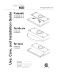
Installation – Mounting Height & Clearance
www.zephyronline.com
ALWAYS, when possible, reduce the number of
transitions and turns. If a long duct run is required,
increase duct size from 8” to 10”.
If turns or transitions are required: Install as far
away from duct opening and as far apart between
the two transitions as possible.
A
n.
mi . B
n
i
m .C
x
ma
D
n.
mi . E
n
mi . F
x
ma
Minimum mount height between range top to hood
bottom should be no less than 26”.
in.
” m x.
26” ma
34
Maximum mount height should be no higher than
34”.
It is important to install the hood at the proper
mounting height. Hoods mounted too low could
UHVXOWLQKHDWGDPDJHDQG¿UHKD]DUGZKLOHKRRGV
mounted too high will be hard to reach and will
ORRVHLWVSHUIRUPDQFHDQGHI¿FLHQF\
”
36
If available, also refer to range manufacturer’s
height clearance requirements and recommended
hood mounting height above range. Always check
your local codes for any differences.
Hood Heights
minimum ducted (A)
minimum recirculating (B)
maximum (C)
Standard
Duct Cover
26-1/2”
31”
50”
Extension
Duct Cover
41-1/2“
46“
80”
Duct cover extension kit available for ceiling
heights up to 12 feet. Turn to page 18 for part
number and ordering information.
Ceiling Heights
minimum ducted (D) 88-1/2” (7’ 4-1/2”) 103-1/2“ (8‘ 7-1/2”)
minimum recirculating (E) 93” (7’ 9”)
108“ (9‘)
maximum (F) 120” (10’)
150” (12’ 6”)
DUCTING
A minimum of 8” round duct is recommended to
PDLQWDLQPD[LPXPDLUÀRZHI¿FLHQF\
Always use rigid type metal ducts only. Flexible
GXFWVFRXOGUHVWULFWDLUÀRZE\XSWR
Use calculation worksheet to compute total duct
ZRUN3DJH
6
DAMAGE-SHIPMENT / INSTALLATION:
3OHDVHIXOO\LQVSHFWXQLWIRUGDPDJHEHIRUH
installation.
,IWKHXQLWLVGDPDJHGLQVKLSPHQWUHWXUQWKH
unit to the store in which it was bought for
repair or replacement.
,IWKHXQLWLVGDPDJHGE\WKHFXVWRPHUUHSDLU
or replacement is the responsibility of the
customer.
,IWKHXQLWLVGDPDJHGE\WKHLQVWDOOHULIRWKHU
WKDQWKHFXVWRPHUUHSDLURIUHSODFHPHQWPXVW
be made by arrangement between customer
and installer.
NEVER exhaust air or terminate duct work into spaces between walls, crawl spaces, ceiling, attics or garages.
All exhaust must be ducted to the outside, unless using the recirculating option.
Use single wall rigid Metal ductwork only.
)DVWHQDOOFRQQHFWLRQVZLWKVKHHWPHWDOVFUHZVDQGWDSHDOOMRLQWVZFHUWL¿HG6LOYHU7DSHRU'XFW7DSH
Some Ducting Options
Roof Pitch w/
Flashing & Cap
(blower
housing)
(blower
housing)
side wall cap
w/ gravity damper
Soffit or crawl space
(blower
housing)
ductless
recirculating
side wall cap
w/ gravity damper
(blower
housing)
7
Installation – Ducting Options
WARNING FIRE HAZARD
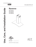
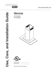
front of hood
side of hood
12 13/16”
12 13/16”
7 13/16”
11 15/16”
Z1C-00VO
min. ducted - 41 1/2”
min. recirc. - 46”
max. - 80”
2 5/8”
14 1/4”
STANDARD
min. ducted - 26 1/2”
min. recirc. - 31”
max. - 50”
23 3/16”
22 1/16”
29 5/16”, 35 7/16”
4 1/8”
top of hood
6 1/16”
Installation – +RRG6SHFL¿FDWLRQV
www.zephyronline.com
AC In
8
71
5/1
6”
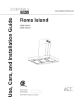
0HDVXUHIURPUDQJHWRSWRKRRGERWWRPDQGPDUNOLQH$´
PLQLPXPIURPUDQJHWRS
2.
Plum and mark center line.
11 1/8”
0DUNPRXQWLQJKHLJKWOLQH%´IURPOLQH$
0DUNPRXQWLQJVSUHDGIURP&/´
)DVWHQ0[´VFUHZVLQWRVWXGVRQOLQH%EXWGR
not tighten all the way. Note: Wood blocking may need
to be added behind the drywall if no studs are present.
Wall anchors may also be used but check local codes
for compliance. Failure to use suitable wall anchors
and screws to hold the weight of the hood could result
in personal injury or damage to the cooking surface or
counter.
14 3/4”
26” min
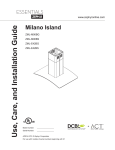
5HPRYHWDSHDQGVFUHZVVHFXULQJHOHFWURQLFVPRXQWLQJ
bracket to hood. Reposition electronics mounting bracket as
VKRZQLQ),*%DQGVHFXUHWRPRWRUKRXVLQJXVLQJWKH
previously removed screws.
5HPRYHVFUHZVVHFXULQJHOHFWULFDOMXQFWLRQER[WR
HOHFWURQLFVPRXQWLQJSODWH5HPRYHMXQFWLRQER[),*%
Brackets are
5HPRYHWKHDOXPLQXPPHVK¿OWHUV
pre-installed
9.
1
Hang hood onto the mounting screws and hand tighten each
VFUHZ),*$6HFXUHWKLUG0[´VFUHZWKURXJKLQVLGH
RIKRRGLQWRZDOOIRUH[WUDVXSSRUW),*$
10. Center and attach duct cover mounting bracket to wall just
EHORZWKHFHLOLQJRUVRI¿WXVLQJ0[´VFUHZV
11. Install electrical and duct work. Seal duct work with aluminum
duct tape. Re-install electrical junction box with cable lock and
LQVWDOOWKHHOHFWULFDO),*%
2
12. Power up hood and check for leaks around duct tape.
3ODFHWHOHVFRSLFGXFWFRYHUVRQWRKRRGDQGH[WHQGLQQHUWRS
duct cover upwards and secure to duct coverEUDFNHWXVLQJ
M3.5 x 8 screws.
FIG. A
5HLQVWDOODOXPLQXPPHVK¿OWHUV
2
* If using hood in recirculating mode you must secure the air diverter
plate onto wall before installing duct work and duct covers. Turn
to page 10 for more details.
!
WARNING: Electrical wiring must be done by a qualified person(s) in
accordance with all applicable codes and standards. This range hood must be
properly grounded. Turn off electrical power at service entrance before wiring.
Cable Lock
1
3
Cable Lock
$FDEOHORFNLQJFRQQHFWRUQRWVXSSOLHGPLJKW
be required by local codes. Check with local
requirements and codes, purchase and install
appropriate connector if necessary.
Motor Housing
FIG. B
9
Installation – Mounting the Hood
! CAUTION: At least two installers are
required due to the weight and size of the
hood.
Installation – Ductless Recirculating
www.zephyronline.com
Ductless recirculation is intended for applications where an exhaust duct work is not possible to be installed.
When converted, the hood functions as a recirculating hood rather than an exhaust hood. Fumes and exhaust
IURPFRRNLQJDUHGUDZQDQG¿OWHUHGE\DVHWRIRSWLRQDOFKDUFRDO¿OWHUV7KHDLULVWKHQSXUL¿HGDQGUH
circulated back within the home.
We recommend to ALWAYS exhaust air outside of the home by employing existing or installing new duct
ZRUNLISRVVLEOH7KHKRRGLVPRVWHIIHFWLYHDQGHI¿FLHQWDVDQH[KDXVWKRRG2QO\ZKHQWKHH[KDXVWRSWLRQ
is not possible should you recourse to converting the hood into a recirculating hood.
:KHQFRQYHUWHGWREHDUHFLUFXODWLQJKRRGDVHWRIFKDUFRDO¿OWHUVDUHUHTXLUHGRQWRSRILWVVWDQGDUG
Aluminum Mesh Filter set. Order according to its Part number below. The standard Aluminum Mesh Filters
DUHLQWHQGHGWRFDSWXUHUHVLGXHIURPFRRNLQJDQGWKHRSWLRQDOFKDUFRDO¿OWHUVKHOSWRSXULI\IXPHVH[KDXVWHG
from cooking for re-circulation.
RECIRCULATING KIT (REQUIRED IF NO DUCTING IS USED)
.LWLQFOXGHVFKDUFRDO¿OWHUVFKDUFRDO¿OWHUEUDFNHWDQGDLUGLYHUWHUSODWH
Hood Model
ZVO-E30AG, ZVO-M90AG
Part No.
ZRC-00VO
Filters in Pkg.
2
1. Purchase recirculating kit per the part number above
6HFXUHDLUGLYHUWHUSODWHWRZDOOEHORZGXFWFRYHUEUDFNHW),*&5XQ
8” ducting from top of hood and secure to air diverter plate.
5HPRYHDOXPLQXPPHVK¿OWHUVIURPKRRG,QVWDOOFKDUFRDO¿OWHUEUDFNHW
LQVLGH¿OWHURSHQLQJ1RWHVFUHZVWRVHFXUHFKDUFRDO¿OWHUEUDFNHWDUH
SUHLQVWDOOHGLQWKHKRRGDQGPXVW¿UVWEHUHPRYHG&OLSFKDUFRDO¿OWHUV
RQWRFKDUFRDO¿OWHUEUDFNHW),*&
5H,QVWDOODOXPLQXPPHVK¿OWHUV
(QDEOHFKDUFRDO¿OWHUFKDQJHLQGLFDWRURQFRQWUROSDQHO5HIHUWRGHWDLOV
RQSJ
&KDUFRDO¿OWHUVPXVWEHUHSODFHGDIWHUHYHU\KRXUVRIXVHRU
approximately every 3 to 4 months based on the average of 1 - 2 hrs.
RIGDLO\FRRNLQJWLPH7KHPLFURSURFHVVRULQWKHFRQWUROVZKHQVHW
ZLOOHODSVHDQGFRXQWXVDJHWLPHDQGLQGLFDWHZKHQFKDUFRDO¿OWHU
replacement is required every 120 hrs.
NOTE: See manual included with recirculating kit for more detailed
instructions.
Charcoal Filter Replacements
Hood Model
ZVO-E30AG, ZVO-M90AG
Part No.
Z0F-C002
Qty to Order
2
'2127:$6+&+$5&2$/),/7(56&KDUFRDO¿OWHUVPD\QHHG
to be changed more often depending on cooking habits.
10
FIG. C
5 Display (speed level, delay off, filter clean/change,clean air)
Lighted Glass Button
clean mesh filter
clean air
replace charcoal filter
Adjust 6 Speed Levels
Lights On/Dim/Off
1 Power / Delay Off Button
Power Button Function
Button will turn power on and off for entire hood (fan and lights).
- Hood will remember the last speed and light level it was turned off at.
(Example: Press Button to turn off hood when on fan speed 4 and high lights. Press
Button again and the hood
will turn back on at speed 4 and high lights level.)
Delay Off Button Function
- Press and hold Button for two seconds and the fan will turn on speed 1. The
Graphic will illuminate. After five minutes
the fan and lights will automatically turn off.
- Pressing Button while Delay Off Function is enabled will turn the hood off and cancel the Delay Off Function.
ACT Verification
- Airflow Control Technology (ACT) allows the installer to set the maximum blower CFM to align with local codes and regulations.
- To verify the maximum blower CFM:
- With hood off, hold the Button for three seconds. The blower CFM will be displayed on the LCD.
2 Speed Selection Button
Fan Speed Decrease Button
- Press this button to decrease fan speed. 6 (burst), 5, 4, 3, 2, 1.
- If fan is On Speed 1 and this button is pressed, fan will power Off.
Fan Speed Increase Button
- Press this button to increase fan speed. Fan On, 1, 2, 3, 4, 5, 6 (burst).
- If hood is Off and this button is pressed, fan will turn On Speed 1.
Burst Mode
- This speed level is intended to be used as a quick burst of air extraction when excess cooking fumes and smoke are
generated. After 3 minutes the fan will automatically change to Speed 5.
3 Lights Button
- Lights are two levels, High and Low.
- From off, press one time for High. LCD will show the words “lights hi” for 2 seconds then fade away.
- Press again for Low. LCD will display the words “lights lo” for 2 seconds then fade away.
- Press again to power lights off.
4 Lighted Glass Button
- Press to cycle glass color from White, Blue, Amber and Off.
- Press and hold for 3 seconds to activate demo mode. While in demo mode each color will gradually change every 10 seconds.
- Pressing
to power off the LED lights will also power off the lighted glass.
11
Features & Controls - Touch Controls
Power / Delay Off
Features & Controls – User Interface
www.zephyronline.com
Mesh Filter Clean Indicator (always enabled)
- After 30 hours of fan usage the Graphic and words “clean mesh filter” will illuminate indicating it is time to clean
the mesh filters. Graphic and words will remain illuminated until reset.
- To reset: With hood off, hold the Button for three seconds, after three seconds the
Graphic and words “clean mesh
filter” will turn off and the 30 hour timer will reset.
Charcoal Filter Replace Indicator (disabled by default, must be enabled if recirculating hood)
- To enable Charcoal Filter Replacement Function:
- With hood off, hold
Button and
Button simultaneously for three seconds. The
Graphic will illuminate for
three seconds indicating the Charcoal Filter Replacement Function is enabled.
- To disable Charcoal Filter Replacement Function:
- With hood off, hold
Button and
Button simultaneously for three seconds. The
Graphic will be
illuminated then turn off indicating the Charcoal Filter Replacement Function is disabled.
- After 120 hours of fan usage the
Graphic and words “replace charcoal filter” will illuminate indicating it is time to
replace the charcoal filter. Graphic and words will remain illuminated until reset.
- To reset: With hood off, hold the
Button for three seconds, after three seconds the
Graphic and words “replace
charcoal filter” will turn off and the 120 hour timer will reset.
Clean Air Indicator
- Clean Air is a feature that turns the fan on every 4 hours for 10 minutes to remove stagnant air in the kitchen.
- To enable Clean Air Function:
- With hood off, hold the Button and
Button simultaneously for three seconds. The
Graphic and
words “clean air” will illuminate and the fan will turn on speed 1 for 10 minutes. After 10 minutes the fan
will turn off and the 4 hour timer will begin.
Graphic will remain on when Clean Air Function is enabled, even if fan is not on.
- To disable Clean Air Function:
- With hood off, hold the
Button and
Button simultaneously for three seconds until
Graphic
turns off.
- When the Clean Air Function is enabled the fan will turn on speed 1 for 10 minutes every 4 hours of non fan usage. After 10
minutes the fan will turn off and the 4 hour timer will reset.
- If the user changes the fan speed while the Clean Air Function is in use, the words “clean air” will turn off but the Graphic
will remain illuminated. If the user presses the Button at any time the 4 hour clean air timer will reset.
12
Clean the hood surface periodically with hot soapy water and clean cotton cloth. Do not use corrosive or
abrasive detergent, or steel wool/scouring pads which will scratch and damage surface.
For heavier soil use liquid degreaser.
After cleaning it is recommended that you use non-abrasive stainless steel polish/cleaners, to polish and
buff out the stainless luster and grain. Always scrub lightly, with clean cotton cloth, and with the grain.
Do not use any product containing chlorine bleach. Do not use “orange” cleaners.
Aluminum Mesh Filters
7KHDOXPLQXPPHVK¿OWHUVLQVWDOOHGE\WKHIDFWRU\DUHLQWHQGHGWR¿OWHURXWUHVLGXHDQGJUHDVHIURP
cooking. They need not be replaced on a regular basis but are required to be kept clean.
$IWHUKRXUVRIXVHWKHZRUGV³FOHDQPHVK¿OWHU´ZLOOLOOXPLQDWHRQWKHFRQWUROVFUHHQLQGLFDWLQJWLPHWR
FOHDQWKHDOXPLQXPPHVK¿OWHUV5HIHUWRLQVWUXFWLRQVRQSDJHRQKRZWRUHVHWWKHLQGLFDWRU)LOWHUV
may need to be cleaned more depending on cooking habits.
Remove and clean by hand or in dishwasher on low heat. Spray degreasing detergent and leave to soak if
heavily soiled.
'U\¿OWHUVDQGUHLQVWDOOEHIRUHXVLQJKRRG
Removing Aluminum Mesh Filters
1. Push in on spring loaded handle
3XOOGRZQRQ¿OWHUKDQGHWRUHPRYH¿OWHU
6KRXOG¿OWHUVZHDURXWGXHWRDJHDQGSURORQJHGXVH
replace with following part number:
Hood Model:
ZVO-E30AG, ZVO-M90AG
Part No.
50200045
Qty to Order
2
13
Maintenance – Hood and Filter Cleaning
SURFACE MAINTENANCE:
Troubleshooting
www.zephyronline.com
TROUBLESHOOTING PROCEDURES FOR VERONA WALL
Issue
Cause
What to do
After installation,
the unit doesn’t
work.
1. The power source is not turned ON.
1. Make sure the circuit breaker and the unit’s
power is ON.
2. The power line and the cable locking connector
is not connecting properly.
2. Check the power connection with the unit is
connected properly.
3. The wires on the control board are loose.
3. Make sure the wires on the control board are
connected properly.
4. The switch board and control board wirings are
disconnected.
4. Make sure the wirings between the switch
board and control board are connected
properly.
5. The switch board or control board is defective.
5. Change the switch board or control board.
1. The blower cable is disconnected.
1. Check all wirings from the blower to be sure
all cables are connected properly.
2. The blower is defective, possibly seized.
2. Change the blower.
3. The thermally protected system detects if the
blower is too hot to operate and shuts the blower
down.
3. The blower will function properly after the
thermally protected system cool down.
4. The switch board or control board is defective.
4. Change defective part.
The LCD screen
is blinking.
1. The cable between the switch board and control
board is disconnected.
1. Check the cable connection between the
switch board and control board.
The unit is
vibrating.
1. The motor is not secure in place.
1. Tighten the motor in place.
2. Damaged blower wheel.
2. Replace the blower.
3. The hood is not secured in place.
3. Check the installation of the hood.
Light works, but
blower is not
turning.
The unit is
whistling.
7KH¿OWHULVQRWLQWKHFRUUHFWSRVLWLRQ
$GMXVWWKH¿OWHUVXQWLOWKHZKLVWOLQJVWRSV
2. The duct pipe connections are not sealed or
connected properly.
2. Check the duct pipe connections to be sure all
connections are sealed properly.
The blower is
working, but the
lights are not.
1. Defective LED bulb.
1. Change the LED bulb.
2. The LED bulb wire is loose.
2. Check LED wire connections at the control
board and the LED light bulbs. Reconnect any
loose wires.
The speed levels
of the blower
sound the same.
1. Using the wrong size of ducting.
1. Change the ducting to at least 8” or higher.
2. ACT enabled blower CFM set to 290 or 390
CFM.
2. Noise level distinction between some speeds
may be minimal when ACT enabled blower is
set to 290 or 390 CFM.
The hood is
not venting out
properly.
1. The hood might be hanging too high from the
cook top.
1. Adjust the distance between the cook top and
the bottom of the hood within 26” and 34”
range.
2. The wind from the opened windows or opened
doors in the surrounding area are affecting the
ventilation of the hood.
2. Close all the windows and doors to eliminate
WKHRXWVLGHZLQGÀRZ
3. Blockage in the duct opening or ductwork.
3. Remove all the blocking from the duct work or
duct opening.
4. The direction of duct opening is against the wind.
4. Adjust the duct opening direction.
5. Using the wrong size of ducting.
5. Change the ducting to at least 8” or higher for
the internal blower.
0HVK¿OWHULVORRVH
1. Make sure the metal clips in the handle are
QRWVWXFN2UUHSODFHWKHPHVK¿OWHU
2. Filter spring clip is loose or broken.
8QLQVWDOODQGUHLQVWDOO¿OWHUSXVKXSRQ¿OWHU
ODWFK5HSODFHPHVK¿OWHULIQHHGHG
Mesh Filter is
vibrating.
14
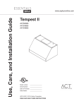
Some local codes limit the maximum amount of CFM a range hood can move. ACT allows you to
control the maximum blower CFM of hoods with Zephyr’s DCBL Suppression System without the need
for expensive make up air kits. ACT enables the installer to easily set the maximum blower speed to
RQHRIWKUHHPRVWFRPPRQO\VSHFL¿HG&)0OHYHOVRU&)07KHXVDJHRI$&7PD\QRWEH
necessary for your installation. Please check your local codes for CFM restrictions.
By default the maximum blower CFM is set to 715.
7RYHULI\LI\RXULQVWDOOHUHQDEOHG$&7:LWKKRRGRIISUHVVDQGKROGWKHSRZHUEXWWRQIRUWKUHHVHFRQGV
Blower CFM will be displayed on the LCD screen. There should also be a foil label located inside the
hood body near the wiring diagram that indicates the blower CFM.
15
Fan Curve Diagrams
ALUÀRZ&RQWURO7HFKQRORJ\$&7
Fan Curve Diagrams
www.zephyronline.com
16
VOLTS
HZ
120
60
MAX AMPS
4
CIRCUIT DIAGRAM
3RZHUFRQVXPSWLRQVKRZQIRUGHIDXOW&)0EORZHUFRQ¿JXUDWLRQ
ACT 590 CFM - Fan Max. 130W @ 1.8A
ACT 390 CFM - Fan Max. 70W @ 1A
ACT 290 CFM - Fan Max. 35W @ .55A
17
Wiring Diagram
ZVO-E30AG, ZVO-M90AG
List of Parts & Accessories
www.zephyronline.com
DESCRIPTION
PART#
Replacement Parts
/LJKW%XOE:/('HDFK
$OXPLQXP0HVK)LOWHUHDFK
=%
Optional Accessories
Recirculating Kit
Replacement Charcoal Filter
Duct Cover Extension
ZRC-00VO
Z0F-C002
Z1C-00VO
To order parts, visit us online at http://store.zephyronline.com or call us at 1.888.880.8368
18
/LPLWHG:DUUDQW\
722%7$,16(59,&(81'(5:$55$17<25)25$1<6(59,&(5(/$7('48(67,216SOHDVHFDOO
=HSK\U 9HQWLODWLRQ //& UHIHUUHG WR KHUHLQ DV ³ZH´ RU ³XV´ ZDUUDQWV WR WKH RULJLQDO FRQVXPHU SXUFKDVHU UHIHUUHG WR
KHUHLQDV³\RX´RU³\RXU´RI=HSK\USURGXFWVWKH³3URGXFWV´ WKDWVXFK3URGXFWVZLOOEHIUHHIURPGHIHFWVLQPDWHULDOV
RUZRUNPDQVKLSDVIROORZV
7KUHH<HDU /LPLWHG :DUUDQW\ IRU 3DUWV )RU WKUHH \HDUV IURP WKH GDWH RI \RXU RULJLQDO SXUFKDVH RI WKH 3URGXFWV ZH
ZLOOSURYLGHIUHHRIFKDUJH3URGXFWVRUSDUWVLQFOXGLQJ/('OLJKWEXOEVLIDSSOLFDEOHWRUHSODFHWKRVHWKDWIDLOHGGXHWR
PDQXIDFWXULQJGHIHFWV:HPD\FKRRVHLQRXUVROHGLVFUHWLRQWRUHSDLURUUHSODFHSDUWVEHIRUHZHHOHFWWRUHSODFHWKH
3URGXFWV
2QH<HDU /LPLWHG :DUUDQW\ IRU /DERU )RU RQH \HDU IURP WKH GDWH RI \RXU RULJLQDO SXUFKDVH RI WKH 3URGXFWV ZH ZLOO
SURYLGHIUHHRIFKDUJHWKHODERUFRVWDVVRFLDWHGZLWKUHSDLULQJWKH3URGXFWVRUSDUWVWRUHSODFHWKRVHWKDWIDLOHGGXHWR
PDQXIDFWXULQJGHIHFWV$IWHUWKHILUVW\HDUIURPWKHGDWHRI\RXURULJLQDOSXUFKDVH\RXDUHUHVSRQVLEOHIRUDOOODERUFRVWV
DVVRFLDWHGZLWKWKLVZDUUDQW\
:DUUDQW\([FOXVLRQV7KLVZDUUDQW\FRYHUVRQO\UHSDLURUUHSODFHPHQWDWRXURSWLRQRIGHIHFWLYH3URGXFWVRUSDUWVDQG
GRHVQRWFRYHUDQ\RWKHUFRVWVUHODWHGWRWKH3URGXFWVLQFOXGLQJEXWQRWOLPLWHGWRDQRUPDOPDLQWHQDQFHDQGVHUYLFH
UHTXLUHGIRUWKH3URGXFWVDQGFRQVXPDEOHSDUWVVXFKDVIOXRUHVFHQWLQFDQGHVFHQWRUKDORJHQOLJKWEXOEVPHVKDQGFKDU
FRDOILOWHUVDQGIXVHVEDQ\3URGXFWVRUSDUWVZKLFKKDYHEHHQVXEMHFWWRIUHLJKWGDPDJHPLVXVHQHJOLJHQFHDFFLGHQW
IDXOW\LQVWDOODWLRQRULQVWDOODWLRQFRQWUDU\WRUHFRPPHQGHGLQVWDOODWLRQLQVWUXFWLRQVLPSURSHUPDLQWHQDQFHRUUHSDLURWKHU
WKDQE\XVFFRPPHUFLDOXVHRIWKH3URGXFWVRUXVHRWKHUZLVHLQFRQVLVWHQWZLWKLWVLQWHQGHGSXUSRVHGQDWXUDOZHDU
RIWKHILQLVKRIWKH3URGXFWVRUZHDUFDXVHGE\LPSURSHUPDLQWHQDQFHXVHRIFRUURVLYHDQGDEUDVLYHFOHDQLQJSURGXFWV
SDGVDQGRYHQFOHDQHUSURGXFWVHFKLSVGHQWVRUFUDFNVFDXVHGE\DEXVHRUPLVXVHRIWKH3URGXFWVIVHUYLFHWULSV
WR\RXUKRPHWRWHDFK\RXKRZWRXVHWKH3URGXFWVJGDPDJHWRWKH3URGXFWVFDXVHGE\DFFLGHQWILUHIORRGVDFWVRI
*RG RU K &XVWRP LQVWDOODWLRQV RU DOWHUDWLRQV WKDW LPSDFW VHUYLFHDELOLW\ RI WKH 3URGXFWV ,I \RX DUH RXWVLGH RXU VHUYLFH
DUHDDGGLWLRQDOFKDUJHVPD\DSSO\IRUVKLSSLQJFRVWVIRUZDUUDQW\UHSDLUDWRXUGHVLJQDWHGVHUYLFHORFDWLRQVDQGIRUWKH
WUDYHOFRVWWRKDYHDVHUYLFHWHFKQLFLDQFRPHWR\RXUKRPHWRUHSDLUUHPRYHRUUHLQVWDOOWKH3URGXFWV$IWHUWKHILUVW\HDU
IURPWKHGDWHRI\RXURULJLQDOSXUFKDVH\RXDUHDOVRUHVSRQVLEOHIRUDOOODERUFRVWVDVVRFLDWHGZLWKWKLVZDUUDQW\
/LPLWDWLRQVRI:DUUDQW\2852%/,*$7,21725(3$,5255(3/$&($7285237,216+$//%(<28562/($1'
(;&/86,9(5(0('<81'(57+,6:$55$17<:(6+$//127%(/,$%/()25,1&,'(17$/&216(48(17,$/25
63(&,$/'$0$*(6$5,6,1*2872)25,1&211(&7,21:,7+7+(86(253(5)250$1&(2)7+(352'8&76
7+((;35(66:$55$17,(6,17+(35(&(',1*6(&7,21$5((;&/86,9($1',1/,(82)$//27+(5(;35(66
:$55$17,(6:(+(5(%<',6&/$,0$1'(;&/8'($//27+(5(;35(66:$55$17,(6)257+(352'8&76
$1'',6&/$,0$1'(;&/8'($//:$55$17,(6,03/,('%</$:,1&/8',1*7+26(2)0(5&+$17$%,/,7<$1'
),71(66)25$3$57,&8/$5385326(6RPHVWDWHVRUSURYLQFHVGRQRWDOORZOLPLWDWLRQVRQWKHGXUDWLRQRIDQLPSOLHG
ZDUUDQW\RUWKHH[FOXVLRQRUOLPLWDWLRQRILQFLGHQWDORUFRQVHTXHQWLDOGDPDJHVVRWKHDERYHOLPLWDWLRQVRUH[FOXVLRQVPD\QRW
DSSO\ WR \RX 7R WKH H[WHQW WKDW DSSOLFDEOH ODZ SURKLELWV WKH H[FOXVLRQ RI LPSOLHG ZDUUDQWLHV WKH GXUDWLRQ RI DQ\ DSSOLFDEOH
LPSOLHGZDUUDQW\LVOLPLWHGWRWKHVDPHWZR\HDUSHULRGGHVFULEHGDERYH$Q\RUDORUZULWWHQGHVFULSWLRQRIWKH3URGXFWVLVIRU
WKHVROHSXUSRVHRILGHQWLI\LQJWKH3URGXFWVDQGVKDOOQRWEHFRQVWUXHGDVDQH[SUHVVZDUUDQW\3ULRUWRXVLQJLPSOHPHQWLQJ
RUSHUPLWWLQJXVHRIWKH3URGXFWV\RXVKDOOGHWHUPLQHWKHVXLWDELOLW\RIWKH3URGXFWVIRUWKHLQWHQGHGXVHDQG\RXVKDOODVVXPH
DOO ULVN DQG OLDELOLW\ ZKDWVRHYHU LQ FRQQHFWLRQ ZLWK VXFK GHWHUPLQDWLRQ :H UHVHUYH WKH ULJKW WR XVH IXQFWLRQDOO\ HTXLYDOHQW
UHIXUELVKHGRUUHFRQGLWLRQHGSDUWVRU3URGXFWVDVZDUUDQW\UHSODFHPHQWVRUDVSDUWRIZDUUDQW\VHUYLFH7KLVZDUUDQW\LVQRW
WUDQVIHUDEOHIURPWKHRULJLQDOSXUFKDVHUDQGDSSOLHVLQWKH8QLWHG6WDWHVDQG&DQDGD
7R2EWDLQ6HUYLFH8QGHU/LPLWHG:DUUDQW\7RTXDOLI\IRUZDUUDQW\VHUYLFH\RXPXVWDQRWLI\XVDWWKHDGGUHVVRU
WHOHSKRQHQXPEHUVWDWHGEHORZZLWKLQGD\VRIWKHGLVFRYHU\RIWKHGHIHFWEJLYHWKHPRGHOQXPEHUDQGSDUWLGHQWLIL
FDWLRQ QXPEHU DQG VHULDO QXPEHU DQG F GHVFULEH WKH QDWXUH RI DQ\ GHIHFW LQ WKH 3URGXFW RU SDUW $W WKH WLPH RI WKH
UHTXHVW IRU ZDUUDQW\ VHUYLFH \RX PXVW SUHVHQW HYLGHQFH RI \RXU SURRI RI SXUFKDVH DQG SURRI RI WKH RULJLQDO SXUFKDVH
GDWH,IZHGHWHUPLQHWKDWWKHZDUUDQW\H[FOXVLRQVOLVWHGDERYHDSSO\RULI\RXIDLOWRSURYLGHWKHQHFHVVDU\GRFXPHQWD
WLRQWRREWDLQVHUYLFH\RXZLOOEHUHVSRQVLEOHIRUDOOVKLSSLQJWUDYHOODERUDQGRWKHUFRVWVUHODWHGWRWKHVHUYLFHV
3OHDVHFKHFNRXUZHEVLWHIRUDQ\UHYLVLRQVZZZ]HSK\URQOLQHFRP
=HSK\U9HQWLODWLRQ6HUYLFH'HSDUWPHQW+DUERU%D\3DUNZD\$ODPHGD&$
$8*
19
Warranty
67$3/(<2855(&(,37+(5(
3URRIRIWKHRULJLQDOSXUFKDVH
GDWHLVQHHGHGWRREWDLQ
VHUYLFHXQGHUZDUUDQW\
www.zephyronline.com
PRODUCT REGISTRATION
Congratulations on your Zephyr range
hood purchase! Please take a moment to
register your new range hood at
www.zephyronline.com/registration
IT’S IMPORTANT
Prompt registration helps in more ways
than one.
Ensures warranty coverage should you
need service.
Ownership verification for insurance
purposes.
Notification of product changes or recalls.
Zephyr Ventilation
|
2277 Harbor Bay Pkwy.
20
|
Alameda, CA 94502
|
1.888.880.8368
Guide d’utilisation, d’entretien et d’installation
www.zephyronline.com
Verona
ZVO-E30AG
ZVO-M90AG
Numéro de modèle : _________________
Numéro de série :
_________________
+
OCT14.0801 © Zephyr Ventilation LLC.
Pour une utilisation avec des modèles de numéros
de série commençant par 24
C
TM
Airflow Control Technology
www.zephyronline.com
INSTALLATION
Feuille de calcul pour le conduit ...........................
Espace libre et hauteur de montage ...................
Options d’installation pour le conduit ..................
6SpFL¿FDWLRQVGHODKRWWH.........................................
Montage de la hotte ...................................................
Reprise d’air sans conduit .......................................
5
6
7
8
9
10
COMMANDES
&RPPDQGHVjHIÀHXUHPHQW.................................. 11
Interface utilisateur ......................................... 12
ENTRETIEN
1HWWR\DJHGHV¿OWUHVHWGHODKRWWH ...................... 13
DÉPANNAGE
................................................................................
14
TABLEAU DE RENDEMENT DU VENTILATEUR ......... 15-16
SCHÉMA DE CÂBLAGE ........................................................... 17
LISTES DES ACCESSOIRES ET DES PIÈCES ............ 18
GARANTIE ...................................................................................... 19
ENREGISTREMENT DU PRODUIT ..................................... 20
1
Table des matières
MISE EN GARDE DE SÉCURITÉ.......................... 2-3
LISTE DU MATÉRIEL ....................................................... 4
Mise en garde de sécurité
LISEZ ET CONSERVEZ CES INSTRUCTIONS
www.zephyronline.com
AVERTISSEMENT
POUR RÉDUIRE LES RISQUES D’INCENDIE OU DE DÉCHARGE ÉLECTRIQUE, N’UTILISEZ PAS CET APPAREIL AVEC UN TABLEAU
DE COMMANDE À SEMI-CONDUCTEURS.
AVERTISSEMENT
POUR RÉDUIRE LES RISQUES D’INCENDIE, DE DÉCHARGE ÉLECTRIQUE OU DE BLESSURE, RESPECTEZ CES CONSIGNES :
a. N’utilisez cet appareil que de la manière prévue par le fabricant. Si vous avez des questions, communiquez avec le fabricant.
b. Avant de procéder au nettoyage ou à l’entretien de l’appareil, éteignez l’alimentation du panneau électrique et bloquez le dispositif de
déconnexion pour éviter que l’alimentation électrique ne soit accidentellement rallumée. Si le dispositif de sectionnement d’électricité ne peut
être bloqué, attachez un avertissement (comme une étiquette) bien en vue sur le tableau électrique.
ATTENTION
Pour ventilation générale seulement. N’utilisez pas cet appareil pour évacuer des vapeurs et des matériaux explosifs ou dangereux. Prenez garde
lors de l’utilisation d’agents nettoyants ou de détergents. Ne devrait être utilisé que dans la cuisine de votre maison.
AVERTISSEMENT
POUR RÉDUIRE LES RISQUES DE FEU DE GRAISSE SUR LA SURFACE DE CUISSON :
a. Ne laissez jamais l’appareil sans surveillance lors de son utilisation à haute température. Les débordements par bouillonnement causent de la
fumée et des déversements de graisse qui peuvent prendre feu. Faites chauffer l’huile à des températures basses ou moyennes.
E $OOXPH]WRXMRXUVODKRWWHORUVTXHYRXVFXLVLQH]jKDXWHWHPSpUDWXUHRXTXHYRXVIDLWHVÀDPEHUGHVDOLPHQWV
F 1HWWR\H]IUpTXHPPHQWOHVYHQWLODWHXUVGHODKRWWH/DJUDLVVHQHGHYUDLWMDPDLVV¶DFFXPXOHUGDQVOHVYHQWLODWHXUVRXOHV¿OWUHV
d. Utilisez des poêlons aux dimensions adéquates. Utilisez toujours une batterie de cuisine correspondant aux dimensions de l’élément.
H $VVXUH]YRXVTXHOHYHQWLODWHXUOHV¿OWUHVHWOHVVXUIDFHVRODJUDLVVHSRXUUDLWV¶DFFXPXOHUVRQWWRXMRXUVSURSUHV
f. Utilisez le réglage haut de la hotte seulement lorsque nécessaire.
g. Ne laissez pas la hotte sans surveillance lorsque vous cuisinez.
h. Utilisez toujours une batterie de cuisine et des ustensiles convenant au type et à la quantité de nourriture que vous préparez.
AVERTISSEMENT
POUR RÉDUIRE LES RISQUES DE BLESSURE LORS D’UN INCENDIE SUR LA SURFACE DE CUISSON :
a. ÉTOUFFEZ LES FLAMMES avec un couvercle, une plaque à biscuits ou un plateau de métal et éteignez ensuite le brûleur. PRENEZ GARDE
$8;5,648(6'(%5Ó/85(6LOHVÀDPPHVQHGLVSDUDLVVHQWSDVe9$&8(=/(6/,(8;(7$33(/(=/(6(59,&('¶,1&(1',(
b. NE PRENEZ JAMAIS UN POÊLON EN FEU – Vous pourriez vous brûler.
c. N’UTILISEZ PAS D’EAU, ou un linge à vaisselle mouillé – une violente explosion de vapeur s’ensuivra.
d. Utilisez un extincteur SEULEMENT si :
1. Vous savez que vous possédez un extincteur de classe ABC et vous savez vous en servir.
2. Le feu est faible et ne s’est pas répandu depuis son point d’origine.
3. Vous avez appelé le service d’incendie.
9RXVSRXYH]VRUWLUIDFLOHPHQWGHO¶HQGURLWRYRXVFRPEDWWH]OHIHX
AVERTISSEMENT
POUR RÉDUIRE LES RISQUES D’INCENDIE, DE DÉCHARGE ÉLECTRIQUE OU DE BLESSURE, SUIVEZ LES CONSIGNES SUIVANTES :
D /HVWUDYDX[G¶LQVWDOODWLRQHWGHFkEODJHpOHFWULTXHGRLYHQWrWUHIDLWVSDUXQHSHUVRQQHTXDOL¿pHVHORQOHVVWLSXODWLRQVGHWRXVOHVQRUPHVHW
standards en vigueur, dont les normes des constructions ayant une cote de résistance au feu.
b. Pour prévenir les contre-explosions, une certaine quantité d’air est nécessaire pour la combustion et l’évacuation des gaz par le carneau
(cheminée) de l’appareil de combustion. Respectez les directives du fabricant d’outillage de chauffage et les normes de sécurité comme celles
publiées par la NFPA (Association nationale des services d’incendie), par la Société américaine des ingénieurs en chauffage, réfrigération et
climatisation (ASHRAE) et par les normes des autorités locales.
c. Lorsque vous coupez ou percez un mur ou un plafond, assurez-vous de ne pas endommager le câblage électrique ou toute autre installation
technique dissimulée.
d. Les ventilateurs canalisés doivent toujours évacuer l’air à l’extérieur.
e. N’installez JAMAIS un interrupteur à une distance atteignable depuis un bain ou une douche.
f. Assurez-vous que l’alimentation électrique est éteinte avant de procéder à l’in tallation, au câblage ou à l’entretien de l’appareil
2
POUR RÉDUIRE LES RISQUES D’INCENDIE, N’UTILISEZ QUE DES CONDUITS D’AÉRATION EN MÉTAL.
ATTENTION
Pour réduire les risques d’incendie et pour évacuer l’air convenablement, assurez-vous de canaliser l’air à l’extérieur de
la maison. N’installez pas l’échappement du conduit dans les espaces entre les murs, le plafond, le grenier, les vides
sanitaires ou le garage.
FONCTIONNEMENT
/DLVVH]WRXMRXUVOHVJULOOHVGHVUHWpHWOHV¿OWUHVHQSODFH6DQVFHVpOpPHQWVOHVYHQWLODWHXUVHQPDUFKHSRXUUDLHQW
accrocher des cheveux, des doigts ou des vêtements amples.
Le fabricant se dégage de toute responsabilité dans les cas de non-respect des instructions transmises dans le présent
manuel pour l’installation, l’entretien et l’utilisation adéquate du produit. Le fabricant se dégage également de toute
UHVSRQVDELOLWpSRXUGHVEOHVVXUHVTXLUpVXOWHUDLHQWGHODQpJOLJHQFHORUVGHO¶XWLOLVDWLRQ'HSOXVODJDUDQWLHSUHQG¿Q
automatiquement lors de l’entretien inapproprié de l’appareil.
*NOTE : Veuillez communiquer avec nous ou visitez le www.zephyronline.com pour obtenir des révisions avant de
procéder à des travaux sur commande.
EXIGENCES ÉLECTRIQUES
Important :
Respectez tous les codes et règlements en vigueur.
Il est de la responsabilité du client de :
&RPPXQLTXHUDYHFXQLQVWDOODWHXUpOHFWULFLHQTXDOL¿p
- S’assurer que l’installation électrique est adéquate et qu’elle respecte le Code national de l’électricité, la plus récente
édition* du ANSI/NFPA 70 ou des normes du CSA C22.1-94, le Code canadien de l’électricité, section 1, la plus récente
édition** du code C22.2 No.0-M91 ainsi que tous les codes et réglements en vigueur.
6LOHVFRGHVSHUPHWWHQWO¶XWLOLVDWLRQG¶XQ¿OGHJDUGHLVROpHWTXHYRXVHQXWLOLVH]XQLOHVWUHFRPPDQGpTX¶XQpOHFWULFLHQ
TXDOL¿pGpWHUPLQHVLOHFKHPLQHPHQWGX¿OHVWDGpTXDW
N’effectuez pas la mise à la terre à un tuyau de gaz.
'HPDQGH]jXQpOHFWULFLHQTXDOL¿pVLYRXVQ¶rWHVSDVFHUWDLQTXHODKRWWHDpWpPLVHjODWHUUHDGpTXDWHPHQW
N’introduisez aucun fusible dans le circuit neutre ou de mise à la terre.
*National Fire Protection Association Batterymarch Park, Quincy, Massachusetts 02269
** CSA International 8501 East Pleasant Valley Road, Cleveland, Ohio 44131-5575
Cet appareil requiert une alimentation électrique de 120V 60Hz. Il doit être connecté à un circuit terminal individuel
dûment mis à la terre, protégé par un disjoncteur de circuit ou un fusible temporisé de 15 ou 20 ampères. Le câblage doit
FRPSWHU¿OVDYHFPLVHjODWHUUH9HXLOOH]YRXVUpIpUHUDX'LDJUDPPHpOHFWULTXHpWLTXHWpVXUO¶DSSDUHLO
Un raccord de câble (non inclus) pourrait également être exigé par les normes et réglementations locales. Informez-vous
des exigences et des normes locales. Achetez et installez le connecteur approprié si nécessaire.
ZVO-E30AG – 223 Watts, 4 Ampères
ZVO-M90AG – 223 Watts, 4 Ampères
&RQVRPPDWLRQFLGHVVXVHVWGHVVSpFL¿FDWLRQVG¶DOLPHQWDWLRQSDUGpIDXW+RWWHVDYHF=HSK\UWHFKQRORJLHpFRXOHPHQW
G¶DLUGHFRQWU{OHH[FOXVLI$&7DSHUPLVFRQVRPPHPRLQVG¶pQHUJLH9RLUOHVFKpPDGHFkEODJHjOD¿QGHFHPDQXHO
pour plus d’informations.
3
Mise en garde de sécurité
ATTENTION
Liste du matériel
www.zephyronline.com
MODÈLES : ZVO-E30AG & ZVO-M90AG
PIÈCES FOURNIES
1 - Hotte avec ventilateur interne
2 - Filtre à tamis en aluminium
1 - Pièce de recouvrement de conduit (haut et bas)
1 - Support mural de recouvrement de conduit
2 - Ampoules DEL 6W
1 - Registre circulaire antirefoulement de 8” (préinstallé)
1 - Trousse de quincaillerie
CONTENU DE LA TROUSSE DE QUINCAILLERIE
(2) vis à tôle vis à tête
cylindrique bombée
(1) rondelle 5 x 12
(2) vis à bois
M6 x 1”
(3) vis à bois
M6 x 1-1/2”
Capuchons de connexion (3)
PIÈCES NON FOURNIES
- Conduit et tous les outils d’installation
- Raccord de câble (si exigé par les codes en vigueur)
- Accessoire – prolongement pour recouvrement de conduit
- Accessoire – ensemble de reprise d’air
4
Equivalent number
length x used
=
Duct pieces
Total
Total
3-1/ 4” x 10” 1 Ft.
Rect.,
straight
x(
) =
Ft.
6”- 8” Round 30 Ft.
wall cap
with damper
x(
) =
Ft.
7” Round,
straight
1 Ft.
x(
) =
Ft.
6”- 8” Round, 30 Ft.
roof cap
x(
) =
Ft.
8” Round,
straight
1 Ft.
x(
) =
Ft.
6” round to
1 Ft.
3-1/ 4” x 10”
rect.
transition
x(
) =
Ft.
3-1/ 4” x 10” 15 Ft.
Rect. 90 0
elbow
x(
) =
Ft.
x(
) =
Ft.
3-1/ 4” x 10” 9 Ft.
Rect. 45 0
elbow
x(
) =
Ft.
6” round to
16 Ft.
3-1/ 4” x 10”
rect.
transition
90 0 elbow
7” or 8”
Round,
90 0 elbow
15 Ft.
x(
) =
Ft.
3-1/ 4” x 10” 24 Ft.
Rect. 90 0
flat elbow
x(
7” or 8”
Round,
45 0 elbow
9 Ft.
x(
) =
Ft.
3-1/ 4” x 10” 30 Ft.
Rect.
wall cap
with damper
x(
7” or 8”
30 Ft.
Round
wall cap
with damper
x(
) =
Ft.
3-1/ 4” x 10” 5 Ft.
Rect. to
6” round
transition
x(
) =
Ft.
7” or 8”
Round,
roof cap
x(
) =
Ft.
3-1/ 4” x 10” 20 Ft.
Rect. to
6” round
transition
90 0 elbow
x(
) =
Ft.
7” round to
8 Ft.
3 1/ 4” x 10”
rect.
transition
x(
) =
Ft.
) =
Ft.
15 Ft.
x(
) =
Ft.
7” round to
23 Ft.
3-1/ 4” x 10”
rect.
transition
90 0 elbow
x(
6” Round,
90 0 elbow
6” Round,
45 0 elbow
9 Ft.
x(
) =
Ft.
Subtotal column 2 =
Ft.
Subtotal column 1 =
Ft.
Total ductwork
Ft.
) =
) =
Subtotal column 1 =
Ft.
Ft.
Ft.
Longueur maximale du conduit d’aération : Pour un
mouvement d’air convenable, la longueur totale d’un conduit
d’aération ne devrait pas compter plus que l’équivalent
de 100 pieds.
5
30 Ft.
=
Installation – Feuille de calcul pour le conduit d’aération
Equivalent number
length x used
=
Duct pieces
Installation – Espace libre et hauteur de montage
www.zephyronline.com
La hauteur de montage minimale ne devrait pas
être moins de 26”.
La hauteur de montage maximale ne devrait pas
outrepasser 34”.
A
n.
mi . B
n
i
m .C
x
ma
D
n.
mi . E
n
mi . F
x
ma
Il est important d’installer la hotte à la hauteur
de montage adéquate. Les hottes installées
trop basses pourraient être endommagées par
la chaleur en plus de présenter des risques
d’incendie plus élevés tandis que les hottes
LQVWDOOpHVWURSKDXWHVVHURQWGLI¿FLOHVjDWWHLQGUH
HWYHUURQWOHXUHI¿FDFLWpHWOHXUUHQGHPHQWUpGXLWV
in.
” max.
6
2 ”m
34
Si elles sont disponibles, consultez les exigences
de hauteur d’espace libre requise par le fabricant
de la cuisinière ainsi que la hauteur recommandée
de montage de la hotte au-dessus de la surface
de cuisson. Informez-vous toujours des normes et
des réglementations locales en vigueur pour toute
différence par rapport aux normes du fabricant.
”
36
Hauteur de la hotte
Ensemble de recouvrement de conduit disponible
pour les plafonds atteignant 12 pieds. Numéro de
pièce et information pour commander disponibles
à la page 18.
Recouvrement de Prolongement de
recouvrement de
conduit standard conduit
minimum avec conduit (A) 26-1/2”
minimum avec reprise d’air (B) 31”
maximum (C) 50”
42-1/2“
46“
80”
Hauteur de plafond
ENDOMMAGEMENT LORS DE LA LIVRAISON/
INSTALLATION :
9HXLOOH]YRXVDVVXUHUTXHWRXWHVOHVSLqFHV
de l’appareil ne sont pas endommagées avant
l’installation.
minimum avec conduit (D) 88-1/2” (7’ 4-1/2”) 103-1/2“ (8‘ 7-1/2”)
minimum avec reprise d’air (E) 93” (7’ 9”)
108“ (9‘)
maximum (F) 120” (10’)
150” (12’ 6”)
CONDUIT D’AÉRATION
Un conduit circulaire de 8” doit être utilisé pour
assurer une circulation d’air maximale.
6LO¶DSSDUHLOHVWHQGRPPDJpGXUDQWODOLYUDLVRQ
UHWRXUQH]O¶DSSDUHLOjO¶HQGURLWRYRXVO¶DYH]
acheté pour réparation ou remplacement.
N’utilisez que des conduits en métal rigide. Les
conduits souples pourraient réduire la circulation
d’air jusqu’à 50 %.
6LO¶DSSDUHLOHVWHQGRPPDJpSDUOHFOLHQWOD
réparation ou le remplacement est à la charge du
client.
Utilisez la feuille de calcul pour obtenir la longueur
totale du conduit (page 5).
6LO¶DSSDUHLOHVWHQGRPPDJpSDUO¶LQVWDOODWHXU
(si autre que le client), le client et l’installateur
doivent en venir à une entente pour la réparation
ou le remplacement.
Lorsqu’il est possible de le faire, diminuez
TOUJOURS le nombre de pièces et de
changements de direction. Si un long tronçon de
conduit est nécessaire, augmentez le diamètre du
conduit de 8” à 10”.
Si des changements de direction ou des
adaptateurs sont nécessaires, installez-les le
plus loin possible de l’ouverture et le plus éloigné
possible l’un de l’autre.
6
N’évacuez ou ne terminez JAMAIS l’échappement du conduit dans les espaces entre les murs, les vides
sanitaires, le plafond, le grenier, ou le garage. Tous les échappements doivent être dirigés à l’extérieur de la
maison, à moins que l’option de reprise d’air ne soit utilisée.
N’utilisez que des conduits en métal pour cloison simple.
Fixez toutes les pièces du conduit avec des vis à tôle et isolez tous les joints avec du ruban adhésif en toile ou
GXUXEDQUpÀHFWHXUFHUWL¿p
Quelques options pour le conduit d’aération
Pente de la toiture
avec solin et chapeau
(Boîtier de
ventilateur)
(Boîtier de
ventilateur)
Bouche d’aération
de mur latéral avec
clapet antirefoulement
Retombée de plafond ou vide sanitaire
Reprise
d’air sans conduit
(Boîtier de
ventilateur)
Bouche d’aération
de mur latéral avec
clapet antirefoulement
7
(Boîtier de
ventilateur)
Installation – Options pour le conduit d’aération
AVERTISSEMENT DE RISQUE D’INCENDIE
Devant de la hotte
Côté de la hotte
12 13/16”
12 13/16”
7 13/16”
11 15/16”
Z1C-00VO
Min. avec conduit - 41 1/2”
Min. avec reprise d’air - 46”
max. - 80”
2 5/8”
14 1/4”
STANDARD
Min. avec conduit - 26 1/2”
Min. avec reprise d’air - 31”
max. - 50”
23 3/16”
22 1/16”
29 5/16”, 35 7/16”
4 1/8”
Dessus de la hotte
6 1/16”
Installation – 6SpFL¿FDWLRQVGHODKRWWH
www.zephyronline.com
Entrée CA
8
71
5/1
6”
1. Prenez la mesure entre la surface de la cuisinière et la base de la hotte; marquez la ligne A
(min. 26” à partir du dessus de la cuisinière).
Support pour le
recouvrement du conduit
11 1/8”
2. Marquez la ligne centrale avec exactitude.
3. Marquez la ligne de hauteur de montage B (à 14-3/4” de la ligne A).
4. Marquez la largeur de montage à partir de la L/C (11-1/8”).
14 3/4”
5. Fixez (2) vis M6 x 1-1/2” aux poutres de la ligne B. Ne tournez pas les vis jusqu’au fond. Note
9RXVSRXUULH]DYRLUjDMRXWHUGHVUHQIRUFHPHQWVGHERLVGHUULqUHODFORLVRQVqFKHVL
aucune poutre n’est présente. Des dispositifs d’ancrage au mur peuvent également
rWUHXWLOLVpVPDLVYpUL¿H]G¶DERUGOHVUpJOHPHQWDWLRQVORFDOHVDYDQWG¶XWLOLVHUGHWHOV
dispositifs.
26” min
6. Enlevez le ruban et les deux vis qui retiennent le support de montage du dispositif électronique
à la hotte. Replacez le support de montage du dispositif électronique comme sur la FIG. B #3
HW¿[H]OHDXERvWLHUGHPRWHXUjO¶DLGHGHVGHX[YLVTXHYRXVDYH]SUpDODEOHPHQWHQOHYpHV
Les supports
(QOHYH]OHVGHX[YLVTXLUHWLHQQHQWODERvWHGHFRQQH[LRQpOHFWULTXHjODSODTXHGHPRQWDJHGX
GLVSRVLWLIpOHFWURQLTXH(QOHYH]ODERvWHGHFRQQH[LRQ),*%
sont préinstallés
(QOHYH]OHVGHX[¿OWUHVjWDPLV
1
9. Accrochez la hotte aux vis de montage et serrez chaque vis à la main (Fig. A#1). Pour plus de
VRXWLHQ¿[H]XQHWURLVLqPHYLV0[´GDQVOHPXUSDUO¶LQWpULHXUGHODKRWWH)LJ$
&HQWUH]HW¿[H]jO¶DLGHGHYLV0[´OHVXSSRUWGHPRQWDJHGXUHFRXYUHPHQWGH
conduit au mur juste en dessous du plafond ou de la retombée de plafond.
11.Installez le conduit d’aération et l’électricité. Scellez le conduit avec du ruban à conduit
HQDOXPLQLXP5pLQVWDOOH]ODERvWHGHFRQQH[LRQDYHFOHUDFFRUGGHFkEOHHWSURFpGH]j
l’installation électrique (FIG. B#2).
2
0HWWH]ODKRWWHVRXVWHQVLRQHWYpUL¿H]V¶LO\DGHVIXLWHVG¶DLUDXWRXUGXUXEDQjFRQGXLW
FIG. A
13.Fixez les plaques de recouvrement coulissantes du conduit à la hotte et faites glisser la plaque
GHUHFRXYUHPHQWLQWpULHXUHSDUWLHVXSpULHXUHYHUVOHKDXW)L[H]ODDXVXSSRUWGH¿[DWLRQGX
recouvrement de conduit à l’aide de deux (2) vis M3.5 x 8”.
2
5pLQVWDOOH]OHV¿OWUHVjWDPLVHQDOXPLQLXP
6LYRXVXWLOLVH]OHPRGHGHUHSULVHG¶DLUYRXVGHYH]¿[HUODSODTXHGXGpÀHFWHXUG¶DLUDXPXU
avant d’installer le conduit et les pièces de recouvrement du conduit. Vous aurez également
jLQVWDOOHUGHV¿OWUHVjFKDUERQHWGHVVXSSRUWV&RQVXOWH]ODSDJHSRXUREWHQLUSOXVGH
détails.
!
AVERTISSEMENT : Le câblage électrique doit être effectué par une ou
des personnes qualifiées selon les stipulations de tous les normes et
standards en vigueur. Éteignez l’alimentation électrique à l’entrée de
service avant de procéder au câblage.
Raccord de câble :
Raccord de câble
1
3
Un raccord de câble (non inclus) pourrait également
être exigé par les normes et réglementations locales.
Informez-vous des exigences et des normes locales.
Achetez et installez le connecteur approprié si
nécessaire.
Boîtier du moteur
FIG. B
9
Installation – Montage de la hotte
! ATTENTION : Compte tenu du poids
et des dimensions de la hotte, au moins
deux installateurs sont nécessaires.
Installation – Reprise d’air sans conduit
www.zephyronline.com
/DFRQ¿JXUDWLRQGHUHSULVHVDQVFRQGXLWDpWpFRQoXHSRXUOHVDSSOLFDWLRQVRLOHVWLPSRVVLEOHG¶LQVWDOOHUXQFRQGXLW
d’aération. Lorsque transformée, la hotte fonctionne comme une hotte de reprise d’air plutôt que comme un système
G¶pYDFXDWLRQG¶DLU/HVYDSHXUVHWIXPpHVGHFXLVVRQVRQWDVSLUpHVHW¿OWUpHVSDUXQHQVHPEOHRSWLRQQHOGH¿OWUHVj
FKDUERQ/¶DLUHVWHQVXLWHSXUL¿pHWUHGLULJpjO¶LQWpULHXUGHODPDLVRQ
Nous recommandons de TOUJOURS évacuer l’air à l’extérieur de la maison en utilisant le conduit en place ou, s’il y
DSRVVLELOLWpHQLQVWDOODQWXQQRXYHDXFRQGXLW/DKRWWHHVWSOXVHI¿FDFHORUVTX¶XWLOLVpHFRPPHV\VWqPHG¶pYDFXDWLRQ
G¶DLU9RXVQHGHYULH]UHFRXULUjODFRQ¿JXUDWLRQGHUHSULVHG¶DLUTXHORUVTX¶LOHVWLPSRVVLEOHG¶LQVWDOOHUXQFRQGXLW
d’aération.
/RUVTXHODFRQ¿JXUDWLRQGHUHSULVHG¶DLUHVWFKRLVLHXQHQVHPEOHGH¿OWUHVjFKDUERQGRLWrWUHLQVWDOOpVXUO¶HQVHPEOH
GH¿OWUHVjWDPLVHQDOXPLQLXP&RPPDQGH]OHVHQYRXVUpIpUDQWDXQXPpURGHSLqFHFLGHVVRXV/HV¿OWUHVj
WDPLVHQDOXPLQLXPVRQWFRQoXVSRXUFDSWXUHUOHVUpVLGXVGHFXLVVRQHWOHV¿OWUHVjFKDUERQRSWLRQQHOVDLGHQWjOD
SXUL¿FDWLRQGHVYDSHXUVHWIXPpHVGHODFXLVVRQORUVGHODUHSULVHG¶DLU
ENSEMBLE DE REPRISE D’AIR (REQUIS SI AUCUN CONDUIT N’EST UTILISÉ)
/¶HQVHPEOHFRPSUHQGGHV¿OWUHVjFKDUERQXQVXSSRUWj¿OWUHVjFKDUERQHWXQGpÀHFWHXUG¶DLU
0RGqOHGHKRWWH
1XPpURGHSLqFH)LOWUHVSDUSDTXHW
ZVO-E30AG, ZVO-M90AG
ZRC-00VO
2
1. Procurez-vous l’ensemble de reprise d’air en utilisant le numéro de pièce
ci-dessus
)L[H]OHGpÀHFWHXUDXPXUVRXVOHVXSSRUWPXUDOGHUHFRXYUHPHQWGH
conduit (FIG. C). Installez le conduit de 8” à la partie supérieure de la
KRWWHHW¿[H]OHjODSODTXHGXGpÀHFWHXUG¶DLU
5HWLUH]OH¿OWUHjWDPLVHQDOXPLQLXPGHODKRWWH,QVWDOOH]OHVXSSRUWGHV
¿OWUHVjFKDUERQGDQVO¶RXYHUWXUHGX¿OWUH1RWH/HVYLVTXLVHUYHQWj
¿[HUOHVXSSRUWGHV¿OWUHVjFKDUERQHQSODFHVRQWSUpLQVWDOOpHVGDQV
ODKRWWHHWGRLYHQWG¶DERUGrWUHHQOHYpHV)L[H]OHV¿OWUHVjFKDUERQDX
VXSSRUWGHV¿OWUHVjFKDUERQ),*&
5pLQVWDOOH]OH¿OWUHjWDPLVHQDOXPLQLXP
$FWLYH]O¶LQGLFDWHXUGHFKDQJHPHQWGHV¿OWUHVjFKDUERQVXUOHWDEOHDXGH
commande (consultez la page 12 pour plus de détails).
/HV¿OWUHVjFKDUERQGRLYHQWrWUHUHPSODFpVDSUqVKHXUHV
d’utilisation (ou approximativement tous les 3-4 mois à raison de 1-2
heures d’utilisation quotidienne). Le microprocesseur des commandes,
lorsqu’il est activé, calcule le temps d’utilisation écoulé et indique quand
OHUHPSODFHPHQWGHV¿OWUHVjFKDUERQHVWUHTXLVWRXWHVOHVKHXUHV
NOTE : Pour plus de détails, consultez le manuel de l’ensemble de
reprise d’air.
)LOWUHVjFKDUERQGHUHPSODFHPHQW
0RGqOHGHKRWWH
1XPpURGHSL4XDQWLWpjFRPPDQGHU
ZVO-E30AG, ZVO-M90AG
Z0F-C002
2
NE NETTOYEZ PAS LES FILTRES À CHARBON. Vous pourriez avoir à
FKDQJHUOHV¿OWUHVjFKDUERQSOXVVRXYHQWVHORQYRVKDELWXGHVFXOLQDLUHV
10
FIG.C
Touche de verre illuminé
clean mesh filter
clean air
replace charcoal filter
Choix de six vitesses
Lumières : Allumer/
Veilleuse/Éteindre
1-Touche de mise en marche/arrêt automatique
Fonction de mise en marche
- La touche
permet d’allumer et d’éteindre la hotte (ventilateur et lumières).
- Lorsqu’elle est éteinte, la hotte garde en mémoire la dernière vitesse et le dernier niveau d’éclairage
(Exemple : Vous appuyez sur la touche
lorsque le ventilateur est à la vitesse 4 et que les lumières sont à haute
intensité. Si vous appuyez de nouveau sur la touche
pour allumer la hotte, le ventilateur se remet en marche à la vitesse 4
et les lumières s’allument à haute intensité).
Fonction d’arrêt automatique
- Appuyez sur le bouton et tenez-le enfoncé pendant deux secondes pour que le ventilateur s’allume à la vitesse 1. Le
symbole
s’illumine. Après cinq minutes, le ventilateur et les lumières s’éteignent automatiquement.
- Si vous appuyez sur le bouton
lorsque la fonction d’arrêt automatique est activée, la hotte s’éteint et annule la fonction
d’arrêt automatique.
Débit d'air contrôle de la technologie (ACT)
- ACT permet à l'utilisateur de contrôler le maximum CFM de la ventilateur.
- Pour vérifier le CFM du vos ventilateur:
- Avec la hotte désactivé, maintenez le bouton
pendant trois secondes. Le CFM de la ventilateur sera
affiché sur l'écran LCD.
2-Touche de choix de vitesse
Touche de réduction de la vitesse du ventilateur
- Appuyez sur ce bouton pour réduire la vitesse du ventilateur. 6 (Rafale), 5, 4, 3, 2, 1.
- Si le ventilateur est à la vitesse 1 lorsque vous appuyez sur cette touche, il s’éteint.
Touche d’augmentation de la vitesse du ventilateur
- Appuyez sur ce bouton pour augmenter la vitesse du ventilateur. 1, 2, 3, 4, 5, 6 (Rafale).
- Si la hotte est éteinte lorsque vous appuyez sur cette touche, le ventilateur s’allume à la vitesse 1.
Mode Rafale
- Cette vitesse est conçue pour changer l’air intensément et rapidement lorsqu’une grande quantité de fumée est générée.
Après trois minutes, le ventilateur passe automatiquement à la vitesse 5.
3-Touche des lumières
- Il y a deux intensités pour les lumières : haute et basse.
- Lorsqu’elles sont éteintes, appuyez une fois pour allumer les lumières à haute intensité. Les mots « lights hi » apparaissent
pendant deux secondes à l’écran LCD.
- Appuyez de nouveau pour les mettre à basse intensité. Les mots « lights lo » apparaissent pendant deux secondes sur l’écran
LCD.
- Appuyez encore une fois pour éteindre les lumières.
4 -Touche de verre illuminé
- Appuyez pour changer la couleur du verre de blanc à bleu à orange et pour l’éteindre.
- Appuyez et tenez la touche enfoncée pendant trois secondes pour activer le mode démo. En mode démo, la touche passe
graduellement d’une couleur à l’autre toutes les dix secondes.
- En appuyant sur
pour éteindre les lumières DEL, le verre illuminé s’éteindra également.
11
Commandes - &RPPDQGHVjHIÀHXUHPHQW
Touche de mise en
5 Affichage (vitesse, arrêt automatique, nettoyage/changement
marche/arrêt automatique
des filtres, purification d’air)
Commandes – Interface utilisateur
www.zephyronline.com
Indicateur de nettoyage des filtres à tamis (toujours en fonction)
- Après 30 heures d’utilisation du ventilateur, le symbole
et les mots « clean mesh filter » s’illuminent, indiquant qu’il est
temps de nettoyer les filtres à tamis. Le symbole et les mots restent illuminés jusqu’à la réinitialisation de la fonction.
- Pour réinitialiser : Lorsque la hotte est éteinte, appuyez et tenez la touche
enfoncée pendant trois secondes. Après
trois secondes, le symbole
et les mots « clean mesh filter » s’éteignent et le temporisateur de 30 heures est réinitialisé.
Indicateur de remplacement du filtre à charbon (désactivé par défaut, doit être activé avec le mode de reprise d’air)
- Pour activer la fonction de remplacement du filtre à charbon :
- Lorsque la hotte est éteinte, appuyez et tenez simultanément les touches
et
pendant trois secondes. Le
symbole
s’illumine pendant trois secondes, indiquant que la fonction de remplacement des filtres est activée.
- Pour désactiver la fonction de remplacement du filtre à charbon :
- Lorsque la hotte est éteinte, appuyez et tenez simultanément les touches
et
pendant trois secondes. Le
symbole
s’illumine pendant trois secondes puis s’éteint, indiquant que la fonction de remplacement des filtres est
désactivée.
- Après 120 heures d’utilisation du ventilateur, le symbole
et les mots « replace charcoal filter » s’illuminent, indiquant qu’il
est temps de remplacer les filtres à charbon. Le symbole et les mots resteront illuminés jusqu’à la réinitialisation de la fonction.
- Pour réinitialiser : Lorsque la hotte est éteinte, appuyez et tenez la touche
enfoncée pendant trois secondes. Après
trois secondes, le symbole
et les mots « replace charcoal filter » s’éteignent et le temporisateur de 120 heures est
réinitialisé.
Indicateur de purification d’air
- La fonction de purification d’air allume le ventilateur pour une période de dix minutes toutes les quatre heures pour enlever
l’air stagnant qui flotte dans la cuisine.
- Pour activer la fonction de purification d’air :
- Lorsque la hotte est éteinte, appuyez et tenez simultanément les touches
et
pendant trois
secondes. Le symbole
et les mots « clean air » s’illuminent et le ventilateur se met en marche à la
vitesse 1 pendant dix minutes. Après dix minutes, le ventilateur s’éteint et le temporisateur de quatre
heures est réinitialisé.
- Le symbole
reste illuminé lorsque la fonction de purification d’air est activée, même si le ventilateur
n’est pas allumé.
- Pour désactiver la fonction de purification d’air :
- Lorsque la hotte est éteinte, appuyez et tenez simultanément les touches
et
pendant trois
secondes jusqu’à ce que le symbole
s’éteigne.
- Lorsque la fonction de purification d’air est activée, le ventilateur fonctionne à la vitesse 1 pendant dix minutes toutes les
quatre heures, lorsque le ventilateur n’est pas utilisé. Après dix minutes, le ventilateur s’éteint et le temporisateur de quatre
heures est réinitialisé.
- Si l’utilisateur change la vitesse du ventilateur lorsque la fonction de purification d’air est en cours de marche, les mots «
clean air » s’éteignent, mais le symbole
reste illuminé. Si l’utilisateur appuie sur la touche , la période de quatre heures
est réinitialisée.
12
Nettoyez régulièrement les surfaces de la hotte avec de l’eau savonneuse chaude et un chiffon de coton propre.
N’utilisez pas de détergent abrasif ou corrosif, de laines d’acier ou de tampons à récurer; ils égratigneront et
endommageront les surfaces.
Pour les taches plus tenaces, utilisez du produit dégraissant liquide.
Après le nettoyage, vous pouvez polir les surfaces avec des produits de polissage à acier inoxydable non
abrasifs pour redonner de l’éclat et du lustre aux surfaces. Frottez toujours doucement, avec un chiffon de coton
propre, et dans le sens du grain.
N’utilisez pas de produits à blanchir au chlore ou d’agents nettoyants « orange ».
Filtre à tamis en aluminium
/HV¿OWUHVjWDPLVHQDOXPLQLXPLQVWDOOpVSDUOHIDEULFDQWRQWSRXUIRQFWLRQGH¿OWUHUOHVUpVLGXVHWODJUDLVVH
de cuisson. Ils ne nécessitent aucun remplacement sur une base régulière, mais doivent être gardés propres.
$SUqVKHXUHVG¶XWLOLVDWLRQOHVPRWV©FOHDQPHVK¿OWHUªV¶LOOXPLQHQWVXUOHWDEOHDXGHFRPPDQGHLQGLTXDQW
TX¶LOHVWWHPSVGHQHWWR\HUOHV¿OWUHVjWDPLVHQDOXPLQLXP&RQVXOWH]ODSDJHSRXUGHVLQVWUXFWLRQVVXUOD
IDoRQGHUpLQLWLDOLVHUO¶LQGLFDWHXU9RXVSRXUULH]DYRLUjQHWWR\HUOHV¿OWUHVSOXVIUpTXHPPHQWVHORQYRVKDELWXGHV
culinaires.
Enlevez-les et nettoyez-les à la main ou au lave-vaisselle avec de l’eau tiède. Vaporisez avec du détergent pour
graisse et laissez tremper pour éliminer la saleté accumulée.
6pFKH]OHV¿OWUHVHWUpLQVWDOOH]OHVDYDQWG¶XWLOLVHUODKRWWH
3RXUHQOHYHUOHV¿OWUHVjWDPLVHQDOXPLQLXP
1. Poussez sur les poignées à ressort
7LUH]VXUODSRLJQpHGX¿OWUHYHUVOHEDVSRXUHQOHYHU
OH¿OWUH
6LOHV¿OWUHVV¶XVHQWHQUDLVRQGHOHXUkJHRXG¶XQH
utilisation prolongée, remplacez-les par les pièces suivantes :
0RGqOHGHKRWWH 1XPpURGHSLqFH4XDQWLWpjFRPPDQGHU
ZVO-E30AG,
50200045
2
ZVO-M90AG
13
Entretien - 1HWWR\DJHGHODKRWWHHWGHV¿OWUHV
ENTRETIEN DES SURFACES:
Dépannage
www.zephyronline.com
PROCÉDURES DE DÉPANNAGE POUR LA HOTTE VERONA WALL
Problème
Cause
Solution
Après
l’installation,
l’appareil ne
fonctionne pas.
1. Le bloc d’alimentation n’est pas allumé
1. Assurez-vous que l’alimentation du disjoncteur
et de l’appareil est allumée
2. La ligne électrique et le raccord de câble ne sont
pas correctement branchés
9pUL¿H]TXHOHEUDQFKHPHQWGHO¶DSSDUHLODpWp
fait correctement
/HV¿OVpOHFWULTXHVGXWDEOHDXGHFRQWU{OHHWGH
commande sont débranchés
$VVXUH]YRXVTXHOHV¿OVpOHFWULTXHVHQWUHOHV
tableaux de contrôle et de commande sont
branchés convenablement
4. Tableau de contrôle/commande défectueux
4. Remplacez le tableau de contrôle/commande
1. Le moteur est défectueux, possiblement bloqué
1. Remplacez le moteur
2. Le système de protection thermale détecte que
le moteur est trop chaud pour fonctionner et
l’éteint.
2. Le moteur fonctionnera normalement lorsque
le système de protection thermale aura refroidi
3. Tableau de contrôle/commande défectueux
3. Remplacez la pièce défectueuse
/HPRWHXUQ¶HVWSDVELHQ¿[pHQSODFH
1. Fixez solidement le moteur en place
Les lumières
fonctionnent,
mais le moteur
ne tourne pas.
L’appareil vibre.
2. La roue du ventilateur est endommagée
2. Remplacez le ventilateur
/DKRWWHQ¶HVWSDVELHQ¿[pHHQSODFH
9pUL¿H]O¶LQVWDOODWLRQGHODKRWWH
4. Tableau de contrôle/commande défectueux
4. Remplacez la pièce défectueuse
Les niveaux
de vitesse de
ODVRXIÀHULHOH
même son.
1. Utilisation de la mauvaise taille de canalisation.
1. Changer le conduit à au moins 8 “ou plus.
$&7SHUPLVVRXIÀHULH&)0jRX&)0
2. Le niveau de bruit distinction entre certains
des vitesses peut être minime quand ACT
permis ventilateur est réglé à 290 ou 390
CFM.
Le moteur
fonctionne, mais
pas les lumières.
1. L’ampoule DEL est défectueuse
1. Remplacez l’ampoule DEL
/H¿OGHO¶DPSRXOH'(/HVWGHVVHUUp
%UDQFKH]OH¿OGHO¶DPSRXOH'(/
La hotte ne
fonctionne pas
bien.
1. La hotte est possiblement installée trop haut par
rapport à la cuisinière
1. Ajustez la distance entre la surface de la
cuisinière et la base de la hotte entre 26” et
34”
2. Du vent provenant d’une fenêtre ou d’une porte
ouverte avoisinante nuit à la ventilation
2. Fermez toutes les portes et fenêtres pour
éliminer les courants d’air
3. L’ouverture du conduit ou le conduit lui-même
est bloqué
3. Enlevez tout ce qui bloque l’ouverture ou le
conduit d’aération
4. L’ouverture du conduit est contre le vent
4. Ajustez l’orientation de l’ouverture du conduit
5. Mauvaises dimensions de conduit d’aération
5. Remplacez le conduit par un conduit adéquat
de 6” de diamètre ou plus pour le ventilateur
interne
/H¿OWUHHQPpWDO /H¿OWUHHQPpWDOHVWGHVVHUUp
vibre.
1. Assurez-vous que les attaches métalliques
de la poignée ne sont pas bloquées. Ou
UHPSODFH]OH¿OWUHjWDPLV
14
Par défaut, le CFM maximale du le ventilateur est réglé à 715.
3RXU YpUL¿HU VL YRWUH LQVWDOODWHXU D SHUPLV $&7 $YHF OH KRWWH GpVDFWLYp DSSX\H] HW PDLQWHQH] OH ERXWRQ
G¶DOLPHQWDWLRQ SHQGDQW WURLV VHFRQGHV /H &)0 GX OH YHQWLODWHXU VHUD DI¿FKp VXU O¶pFUDQ /&' ,O \ D GHYUDLW
également être une étiquette feuille d’aluminium situé à l’intérieur du corps de la hotte à proximité de la schéma
de câblage qui indique le CFM du le ventilateur.
15
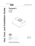
Tableau De Rendement Du Ventilateur
'pELWG¶DLUFRQWU{OHGHODWHFKQRORJLH$&7
Certains codes locaux de limiter le montant maximum de CFM qu’une hotte de cuisinière peut se déplacer.
ACT vous permet de contrôler le maximum CFM de les hottes avec le système de répression DCBL à partir
de Zephyr sans avoir besoin de coûteux kits pour l’air de remplacement. ACT permet à l’installateur de régler
facilement la vitesse maximale du ventilateur à l’un des trois les plus couramment prescrits niveaux de CFM;
RX &)0 /¶XWLOLVDWLRQ GH O¶$&7 SHXWrWUH SDV QpFHVVDLUH SRXU YRWUH LQVWDOODWLRQ 6¶LO YRXV SODvW
YpUL¿H]YRVFRGHVORFDX[SRXUFRQQDvWUHOHVUHVWULFWLRQVGHV&)0
Courbe de rendement du ventilateur, 390 CFM
Entree en CA: 120V, 60 Hz
Diametre du conduit de sortie : 8”
Pression (en TQ)
Tableau De Rendement Du Ventilateur
www.zephyronline.com
Debit (pi3/min)
16
VOLTS
HZ
MAX AMPS
120
60
4
SCHEMA DE CIRCUITS
MOTEUR
CC
DEL DEL
BRANCHEMENT
DES COMMANDES
DEL
CCI DES DEL
INTERRUPTEUR
CCI DES DEL
CCI DES DEL
VERT
HAUTLAMPE
NOIR
BAS
BLANC
CCI DES COMMANDES
BOÎTIER
CCI DES DEL
&RQVRPPDWLRQPRQWUpSRXUGpIDXWGHFRQ¿JXUDWLRQGXYHQWLODWHXU&)0
ACT 590 CFM - Ventilateur Max. 130W @ 1.8A
ACT 390 CFM - Ventilateur Max. 70W @ 1A
ACT 290 CFM - Ventilateur Max. 35W @ .55A
17
6FKpPDGHFkEODJH
ZVO-E30AG, ZVO-M90AG
Listes des pièces et des accessoires
www.zephyronline.com
NO DE PIÈCE
DESCRIPTION
Pièces de remplacement
Ampoule DEL 6W (chaque)
Filtre à tamis en aluminium (chaque)
Z0B-0034
50200045
Accessoires optionnels
Ensemble de reprise d’air
Filtre à charbon de remplacement
Ensemble de prolongement de recouvrement de conduit
ZRC-00VO
Z0F-C002
Z1C-00VO
Pour commander des pièces, visitez-nous en ligne au www.zephyronline.com ou communiquez
avec nous par téléphone au 1-888-880-8368
18
8QHSUHXYHGHODGDWHG¶DFKDWRULJLQDOH
HVWQpFHVVDLUHSRXUREWHQLUGXVHUYLFH
ORUVTXHOHSURGXLWHVWVRXVJDUDQWLH
*DUDQWLHOLPLWpH
32852%7(1,5'86(59,&(6286*$5$17,(2832857287(48(67,21/,e(¬/¶(175(7,(1
YHXLOOH]FRPPXQLTXHUDYHFQRXVDX
=HSK\U 9HQWLODWLRQ //& GpVLJQp DX[ SUpVHQWHV VRXV OH QRP GH © QRXV ª JDUDQWLW DX SUHPLHU DFKHWHXU GpVLJQp DX[
SUpVHQWHVVRXVOHQRPGH©YRXVªRX©YRWUHªGHSURGXLWV=HSK\UOHV©3URGXLWVªTXHOHVGLWVSURGXLWVVRQWH[HPSWV
GHGpIDXWVGHIDEULFDWLRQRXGHPDLQG¶°XYUHVHORQOHVFRQGLWLRQVVXLYDQWHV
*DUDQWLH GH WURLV DQV VXU OHV SLqFHV *DUDQWLH GH WURLV DQV j SDUWLU GH OD GDWH G¶DFKDW RULJLQDOH GX 3URGXLW 1RXV
IRXUQLURQVVDQVIUDLVOHV3URGXLWVRXOHVSLqFHV\FRPSULVOHVDPSRXOHV/('OHFDVpFKpDQWGHUHPSODFHPHQWTXLFRP
SRUWDLHQW GHV GpIDXWV GH IDEULFDWLRQ 1RXV SRXUULRQV FKRLVLU j QRWUH VHXOH GLVFUpWLRQ GH UpSDUHU RX GH UHPSODFHU GHV
SLqFHVDYDQWGHSUHQGUHODGpFLVLRQGHUHPSODFHUOH3URGXLW
*DUDQWLHOLPLWpHG¶XQDQVXUODPDLQG¶°XYUH*DUDQWLHG¶XQDQjSDUWLUGHODGDWHG¶DFKDWRULJLQDOHGX3URGXLW1RXV
FRXYULURQVVDQVIUDLVOHVIUDLVGHPDLQG¶°XYUHDIIpUHQWVjODUpSDUDWLRQGX3URGXLWRXGHVSLqFHVGHUHPSODFHPHQWTXL
FRPSRUWDLHQWGHVGpIDXWVGHIDEULFDWLRQ8QDQDSUqVODGDWHG¶DFKDWRULJLQDOHYRXVVHUH]UHVSRQVDEOHGHWRXVOHVIUDLV
GHPDLQG¶°XYUHDVVRFLpVjODSUpVHQWHJDUDQWLH
([FOXVLRQVGHODJDUDQWLH&HWWHJDUDQWLHQHFRXYUHTXHODUpSDUDWLRQRXOHUHPSODFHPHQWjQRWUHJUpGHSLqFHVRX
GH3URGXLWVGpIHFWXHX[HWQHFRXYUHDXFXQDXWUHFRWDIIpUHQWDX[3URGXLWVGRQWVDQVV¶\OLPLWHUOHVIUDLVOLpVDj
O¶HQWUHWLHQQRUPDOGHV3URGXLWVHWDXUHPSODFHPHQWGHVSLqFHVFRQVRPPDEOHVFRPPHOHVIOXRUHVFHQWLQFDQGHVFHQFH
RXKDORJqQHDPSRXOHVOHVILOWUHVPpWDOOLTXHVOHVILOWUHVjFKDUERQHWOHVIXVLEOHVEjWRXW3URGXLWRXSLqFHD\DQWpWp
HQGRPPDJpGXUDQWOHWUDQVSRUWRXpWDQWOHUpVXOWDWG¶XQPDXYDLVXVDJHG¶XQHQpJOLJHQFHG¶XQDFFLGHQWG¶XQHLQVWDOOD
WLRQLQFRUUHFWHRXQHUHVSHFWDQWSDVOHVQRWLFHVG¶LQVWDOODWLRQUHFRPPDQGpHVG¶XQHQWUHWLHQRXG¶XQHUpSDUDWLRQLQDS
SURSULp GRQW QH QRXV VRPPHV SDV UHVSRQVDEOHV F j XQH XWLOLVDWLRQ FRPPHUFLDOH RX QH FRUUHVSRQGDQW SDV j
O¶XWLOLVDWLRQSRXUODTXHOOHOHV3URGXLWVVRQWFRQoXVGjO¶XVXUHQDWXUHOOHGXILQLjO¶XVXUHGXHjXQHQWUHWLHQLQDGpTXDW
j O¶XWLOLVDWLRQ GH SURGXLWV QHWWR\DQWV FRUURVLIV RX DEUDVLIV GH WDPSRQV QHWWR\HXUV HW GH SURGXLWV GH QHWWR\DJH SRXU OH
IRXUHDX[pFODWVHQWDLOOHVRXILVVXUHVUpVXOWDQWG¶XQDEXVRXG¶XQHPDXYDLVHXWLOLVDWLRQGX3URGXLWIDX[GpSODFH
PHQW G¶XQ WHFKQLFLHQ GH VHUYLFH j YRWUH GRPLFLOH SRXU YRXV PRQWUHU FRPPHQW XWLOLVHU OHV 3URGXLWV J DX[ GRPPDJHV
FDXVpVSDUXQDFFLGHQWXQLQFHQGLHXQHLQRQGDWLRQXQFDVIRUWXLWRXK/HVLQVWDOODWLRQVSHUVRQQDOLVpHVRXPRGLILFD
WLRQVTXLRQWXQLPSDFWPDLQWHQDELOLWpGX3URGXLW6LYRXVYRXVWURXYH]jO¶H[WpULHXUGXWHUULWRLUHTXHQRXVGHVVHUYRQV
GHVIUDLVVXSSOpPHQWDLUHVSRXUUDLHQWV¶DSSOLTXHUSRXUODOLYUDLVRQGHVSURGXLWVjQRVSRLQWVGHVHUYLFHGpVLJQpVSRXUXQH
UpSDUDWLRQVRXVJDUDQWLHRXYRXVSRXUULH]DYRLUjGpERXUVHUOHVIUDLVGHGpSODFHPHQWGXWHFKQLFLHQjYRWUHGRPLFLOHSRXU
TXHOH3URGXLWVRLWUpSDUpHQOHYpRXUpLQVWDOOp8QDQDSUqVODGDWHG¶DFKDWRULJLQDOHGX3URGXLWYRXVrWHVpJDOHPHQW
UHVSRQVDEOHGHWRXVOHVIUDLVGHPDLQG¶°XYUHDVVRFLpVjODSUpVHQWHJDUDQWLH
5HVWULFWLRQVGHODJDUDQWLH1275(2%/,*$7,21'(5e3$5(528'(5(03/$&(5¬1275(*5e/(352'8,7
&2167,78( 9275( 6(8/ (7 81,48( 5(&2856 6286 /$ 35e6(17( *$5$17,( 1286 1( 1286 3257216
3$65(63216$%/(632857287'200$*(,1',5(&7$&&(662,5(283$57,&8/,(55e68/7$1728$<$17
81 /,(1$9(& /¶87,/,6$7,21 28 /( 5(1'(0(17 '(6 352'8,76 /(6 *$5$17,(6 (;35(66(6 '( /$ 6(&
7,2135e&e'(17(6217(;&/86,9(6(77,(11(17/,(8'(7287($875(*$5$17,((;35(66(3$5/(6
35e6(17(612865(-(7216(7(;&/82167287($875(*$5$17,((;35(66(3285/(6352'8,76(7
7287(6 /(6 *$5$17,(6 7$&,7(6 35e98(6 3$5 /$ /2, '217 &(//(6 5(/$7,9(6 ¬ /$ 48$/,7e
0$5&+$1'( 28 ¬ /
$'e48$7,21 '8 352'8,7 3285 81( 87,/,6$7,21 3$57,&8/,Ê5( &HUWDLQV eWDWV RX
SURYLQFHVQ¶DXWRULVHQW SDV OHV UHVWULFWLRQV VXU OD GXUpH G¶XQH JDUDQWLH LPSOLFLWH RX O¶H[FOXVLRQ RX OD UHVWULFWLRQ GHV GRP
PDJHVLQGLUHFWVRXDFFHVVRLUHVSDUFRQVpTXHQWOHVH[FOXVLRQVHWUHVWULFWLRQVPHQWLRQQpHVFLGHVVXVSRXUUDLHQWQHSDV
V¶DSSOLTXHU j YRWUH FDV 'DQV OD PHVXUH R XQH ORL DSSOLFDEOH LQWHUGLW O¶H[FOXVLRQ GH JDUDQWLHV LPSOLFLWHV OD GXUpH GH
WRXWHJDUDQWLHLPSOLFLWHDSSOLFDEOHVHOLPLWHjODSpULRGHGHGHX[DQVGpFULWHFLGHVVXV/¶XQLTXHREMHFWLIGHWRXWHGHVFULS
WLRQRUDOHRXpFULWHHVWGHSUpVHQWHUOHV3URGXLWVHWFHOOHFLQHGHYUDLWSDVrWUHLQWHUSUpWpHFRPPHXQHJDUDQWLHH[SUHVVH
$YDQWG¶XWLOLVHURXGHSHUPHWWUHO¶XWLOLVDWLRQGHV3URGXLWVYRXVGHYUH]GpWHUPLQHUVLOHV3URGXLWVFRQYLHQQHQWDX[XWLOLVD
WLRQVSUpYXHVHWYRXVGHYUH]DVVXPHUWRXWULVTXHHWWRXWHUHVSRQVDELOLWpUHODWLIVjFHVXWLOLVDWLRQV1RXVQRXVUpVHUYRQV
OHGURLWG¶XWLOLVHUGHVSLqFHVUHFRQVWUXLWHVRXUHPLVHVjQHXISRXUUHPSODFHUO¶XQHGHVIRQFWLRQQDOLWpVGDQVOHFDGUHGH
ODSUpVHQWHJDUDQWLHRXGHO¶XQHGHVSDUWLHVGHODSUpVHQWHJDUDQWLH/¶DFKHWHXURULJLQDOQHSHXWWUDQVIpUHUODSUpVHQWH
JDUDQWLHHWFHOOHFLQ¶HVWYDOLGHTX¶DX[eWDWV8QLVHWDX&DQDGD
3RXUREWHQLUGXVHUYLFHVRXVODJDUDQWLH3RXUDYRLUGURLWjGXVHUYLFHVRXVJDUDQWLHYRXVGHYH]DQRXVDYHUWLU
HQXWLOLVDQWO¶DGUHVVHRXOHQXPpURGHWpOpSKRQHLQVFULWFLGHVVRXVGDQVOHVVRL[DQWHMRXUVVXLYDQWODGpWHFWLRQGXGpIDXW
E GRQQHU OH QXPpUR GX PRGqOH OH QXPpUR G¶LGHQWLILFDWLRQ GH OD SLqFH
DLQVL TXH OH QXPpUR GH VpULH HW F GpFULUH OD
QDWXUHGHWRXWGpIDXWGHODSLqFHRXGX3URGXLW$XPRPHQWGHIDLUHODGHPDQGHGHVHUYLFHVRXVJDUDQWLHYRXVGHYUH]
SUpVHQWHUYRWUHSUHXYHG¶DFKDWHWODSUHXYHGHODGDWHG¶DFKDWRULJLQDOH6LQRXVGpWHUPLQRQVTXHOHVH[FOXVLRQVGHOD
JDUDQWLHpQXPpUpHVFLGHVVXVV¶DSSOLTXHQWRXVLYRXVYRXVWURXYH]GDQVO¶LQFDSDFLWpGHQRXVIRXUQLUODGRFXPHQWDWLRQ
QpFHVVDLUH SRXU REWHQLU GX VHUYLFH YRXV VHUH] UHVSRQVDEOH GH WRXV OHV IUDLV G¶H[SpGLWLRQ GH GpSODFHPHQW GH
PDLQG¶°XYUHRXGHWRXWDXWUHFRWDIIpUHQWDXVHUYLFH
9HXLOOH]FRQVXOWHUQRWUHVLWH:HEDXZZZ]HSK\URQOLQHFRPSRXUVDYRLUVLGHVUpYLVLRQVRQWpWpDSSRUWpHVjODJDUDQWLH
=HSK\U9HQWLODWLRQ6HUYLFH'HSDUWPHQW+DUERU%D\3DUNZD\$ODPHGD&$
$8*
19
Garantie
$*5$)(=9275(5(d8,&,
www.zephyronline.com
ENREGISTRMENT DU PRODUIT
Nous vous félicitons d’avoir acheté une
hotte Zephyr. Veuillez prendre un moment
pour enregistrer votre nouvelle hotte au
www.zephyronline.com/registration
C’EST IMPORTANT
Cet enregistrement rapide est utile à
bien des égards.
Il assure la couverture de votre garantie si vous
avez besoin de service après-vente.
À des fins d’assurance, il permet de confirmer
que vous êtes le propriétaire.
Il vous permet de recevoir des avis concernant
des modifications ou des rappels de produits.
Zephyr Ventilation
|
2277 Harbor Bay Pkwy.
20
|
Alameda, CA 94502
|
1.888.880.8368