1
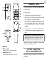
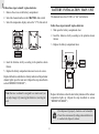
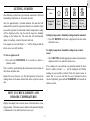
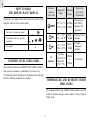
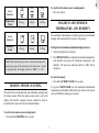
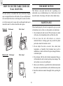
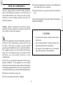
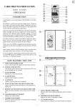
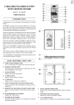
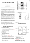
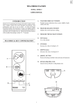
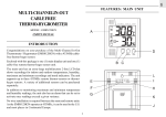
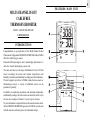
GB
FEATURES: MAIN UNIT
MULTI-CHANNEL IN-OUT
CABLE FREE
THERMO-HYGROMETER
MODEL : EMGR819LR (MRC800)
USER’S MANUAL
INTRODUCTION
Congratulations on your purchase of the Multi-Channel In-Out
Thermometer / Hygrometer EMGR819LR (MRC800) with a 433MHz
cable-free thermo-hygro sensor.
Enclosed with this package is one (1) main display unit and one (1)
cable-free remote thermo-hygro sensor unit.
The main unit has an extra-large multifunction 2-line LCD that
shows recordings for indoor and outdoor temperatures and
humidity, maximum and minimum recordings and trend indicators.
The unit supports up to three 433MHz remote thermo-sensors or
thermo-hygro sensors. A variety of additional sensors can be
purchased separately.
In addition to monitoring maximum and minimum temperature
and humidity readings, the unit also has an alarm that can be set to
activate once readings of channel 1 exceed a given variance.
No wire installation is required between the main and remote units.
As the EMGR819LR (MRC800) operates at 433MHz, it can be used
in North America and most places in Continental Europe.
1
GB
A Extra large two-line Liquid Crystal Display (LCD)
Multifunction display showing temperature and humidity,
max./min. memory as well as trend indicators for the main
unit and remote sensors.
I
°C/°F slide switch
Selects between degree Centigrade (°C) and Fahrenheit (°F)
J
Battery compartment
Accommodates two AA-size batteries
B CHANNEL button
- Selects among different channels
- Activates remote sensor scanning mode
K Retractable table stand
For standing the main unit on a flat surface
L Recessed Wall-mount hole
For mounting the main unit on a wall
C IN/REMOTE
- Selects between the main-unit display and a selected
remote unit
- Activates search mode
M Retractable Antenna
For reception of remote signal
D MEM/CLEAR button
- Recalls the maximum or minimum temperature and
humidity readings
- Clears the maximum and minimum temperature and
humidity memory of remote sensor channels or the main
unit display
FEATURES: REMOTE
THERMO-HYGRO SENSOR
A Two-line LCD
Displays the current temperature and humidity monitored by
the remote unit
E HI/LO button
- Set the upper or lower temperature alarm limits of
channel 1
- Confirms alarm settings
F
B LED indicator
Flashes when the remote unit transmits a reading
C °C/°F slide switch
Selects between Centigrade (°C) and Fahrenheit (°F)
button
Sets the readings for the upper or lower temperature and
humidity channel 1
D Channel slide switch
Designates the remote unit Channel 1, Channel 2 or
Channel 3
G AL ON/OFF button
Activates or deactivates alarm
E RESET
Returns all settings to default values
H RESET
Returns all settings to default values and erases all
memories
F
2
Battery compartment
Accommodates two AA-size batteries
GB
BEFORE YOU BEGIN
To ensure proper functioning of the EMGR819LR (MRC800) follow
this setup procedure.
For best operation:
1. Assign different channels to different remote units.
2. Insert batteries for remote units before doing so for the main
unit (see instructions for battery installation).
3. Place the main unit as close as possible next to the remote unit,
reset the main unit after installing batteries. This will ensure
easier synchronization between the transmission and reception
of signals.
4. Position the remote unit and main unit within effective
transmission range, which, in usual circumstances, is up to 100
meters.
Note that the effective range is vastly affected by the building
materials and where the main and remote units are
positioned. Try various set-ups for best result.
Though the remote units are weather proof, they should be placed
away from direct sunlight, rain or snow.
G Battery door
H Wall-mount holder
Supports the remote unit in wall-mounting
I
BATTERY AND CHANNEL
INSTALLATION: REMOTE UNIT
Removable table stand
For standing the remote unit on a flat surface
The remote thermo-hygro sensor unit uses two (2) UM-3 or “AA”
size batteries.
3
GB
Follow these steps to install / replace batteries:
BATTERY INSTALLATION: MAIN UNIT
1. Remove the screws on the battery compartment.
The main unit uses two (2) UM-3 or “AA” size batteries.
2. Select the channel number on the CHANNEL slide switch.
3. Select the temperature display unit on the °C/°F slide switch.
Follow these steps to install / replace batteries:
1. Slide open the battery compartment door.
2. Insert the batteries strictly according to the polarities shown
therein.
3. Replace the battery compartment door.
4. Insert the batteries strictly according to the polarities shown
therein.
5. Replace the battery compartment door and secure its screws.
Replace the batteries when the low-battery indicator of the particular
channel lights up on the main unit. (Repeat the steps described in
section “BEFORE YOU BEGIN”)
Note that once a channel is assigned to a remote unit, you
can only change it by removing the batteries or resetting the
unit.
Replace the batteries when the low-battery indicator of the indoors
temperature lights up. (Repeat the steps described in section
“BEFORE YOU BEGIN”)
If not disposed of properly, batteries can be harmful.
Protect the environment by taking exhausted batteries
to authorized disposal stations.
4
GB
GETTING STARTED
Kinetic-wave
Icon
Once batteries are placed in a given remote sensor unit, it will start
transmitting information at 40-second intervals.
Designated
Display
Also, for approximately a 3-minute duration, the main unit will
automatically search for signals once batteries are installed. Upon
successful reception, the individual channel temperature reading
will be displayed on the top line and the respective humidity
reading on the bottom line. The main unit will automatically
update its readings at about 40-second intervals.
Indoor
Display
Remote
Remote
Remote
Display
Display
Display
Channel One Channel Two Channel Three
To display temperature / humidity readings from the main unit:
• Press IN / REMOTE until a dot is displayed in the box under
the kinetic-wave.
If no signals are received, blanks “ --- ” will be displayed and the
kinetic wave icon will not show.
To display temperature / humidity readings from a remote
sensor:
To force a signal search:
• Press CHANNEL until the appropriate remote sensor channel is
displayed in the box under the kinetic-wave.
• Press and hold IN/REMOTE for 2-seconds to enforce a
3-minute search.
If no readings are received from one particular channel for more
than 15 minutes, blanks “ --- ” will be displayed until further
readings are successfully searched. Check the remote sensor to
ensure that it is secure and that the correct channel has been
selected. Optionally, press and hold IN/REMOTE for 2-seconds to
enforce a search.
This is useful in synchronizing the transmission and reception of
the remote and main units.
Repeat this step whenever you find discrepancies between the
reading shown on the main unit and that on the respective remote
unit.
HOW TO CHECK REMOTE AND
INDOORS TEMPERATURES
Display of readings from a remote sensor or the main unit is a onestep procedure. The remote sensor channel or the main unit display
is indicated in a box under the kinetic-wave icon.
5
GB
Indicator
displays
on the unit
HOW TO READ
THE KINETIC-WAVE DISPLAY
The kinetic-wave display shows the signal-receiving status of the
main unit. There are three possible forms:
Temperature
Range
Humidity
Range
Shows that
the Current
Environment
20°C to 25°C
(68°F to 77°F)
40%RH70%RH
Ideal range for
both relative
humidity and
temperature
-5°C -+ 50°C
(23°F - 122°F)
OVER70%RH
Contains excess
moisture
-5°C -+ 50°C
(23°F - 122°F)
Below
70%RH
Contains
inadequate
moisture
Less than
20°C( 68°F) or
More than
25°C (77°F)
40%RH
to
70%RH
No comment
The unit is in searching mode.
Transmission data are securely
registered.
No signals.
No
Indicator
COMFORT LEVEL INDICATORS
The comfort level indicators COMFORT, WET or DRY will tell you
if the curent environment is comfortable, too wet or too dry.
The comfort indicators will appear on the display of the main unit
when the following conditions are satisfied:
TEMPERATURE AND HUMIDITY TREND
INDICATORS
The temperature-trend and humidity-trend indicators show the
trends of collected readings. Arrows indicate a rising, steady or
falling trend.
6
Temperature
Trend
• Press any button.
Rising
Steady
Falling
MAXIMUM AND MINIMUM
TEMPERATURE AND HUMIDITY
The maximum and minimum recorded temperature and humidity
readings will automatically be stored in the memory.
Arrow
indicator
Humidity
Trend
Rising
Steady
To display the maximum and minimum display memory:
Falling
1. Select the channel to be checked.
2. Press MEM/CLEAR once to display the maximum temperature
and humidity and again the minimum temperature and
humidity. The respective indicators, MAX or MIN will be
displayed.
Note: If the temperature goes above or below the temperature
measuring range of the main unit or the remote unit ( stated
in specification), the display will show “HHH” or “LLL”.
To clear the memory:
• Press and hold MEM/CLEAR for 2-seconds.
REMOTE SENSOR SCANNING
If you press MEM/CLEAR now, the maximum and minimum
temperatures and humidity will have the same values as the current
ones until different readings are recorded.
The unit can be set to automatically scan and display readings from
the remote sensors. When the remote-sensor mode is active, the
display will show the readings from one channel for about 4second and then proceed to the next channel display.
To activate the remote-sensor scanning mode:
• Press and hold CHANNEL for 2-seconds.
7
GB
To deactivate the remote-sensor scanning mode:
Arrow
indicator
GB
Note:
HOW TO USE CHANNEL-1
TEMPERATURE/HUMIDITY ALARM
The temperature range is from -50°C (-58°F) to +70°C
(158°F).
Upper and lower temperature and humidity limits for channel-1 can
be set so that an alarm activates when the limits are exceeded.
If this is the first time you set the limits, the lower limit will
start from -50°C (-58°F) and the upper limit +70°C (158°F).
Otherwise, the reading will start from the temperature last
selected.
The high and low temperature and humidity displays are selected
by sequentially pressing HI/LO.
The humidity range is from 2% to 98%.
The high-low displays are as follows:
Sequence
Pressing HI/LO once
If this is the first time you set the limits, the lower limit will
start from 2% and the upper limit 98% Otherwise, the reading
will start from the humidity last selected.
Respective Display
Enters HI temperature display
Pressing HI/LO twice
Enters HI humidity display
Pressing HI/LO three times
Enters LO temperature display
Pressing HI/LO a four time
Enters LO humidity display
3. Repeat the steps to set the upper humidity setting and the lower
temperature and humidity settings.
4. When finished, press HI/LO to set another limit or wait
16-seconds and the unit will automatically return to the normal
display. The respective HI, LO or both indicators will light up
to signify the status of the alarm.
To set a high or low temperature or humidity alarm:
If in another channel other than channel one is selected, when the
alarm activates the display will switch to channel-1 and the display
will flash. If left untouched, the alarm will activate for 1-minute.
Press any key to momentarily stop the alarm. The alarm will activate
again if the limit continues to be exceeded.
1. Press HI/LO, channel-1 will be displayed.
2. Press to set the temperature or humidity limit. Each press will
increase increments by one degree or percentage. Press and
hold the button for a rapid-scrolling sequence by increments of
five.
Note: If a second limit is passed while an alarm is active, the
first alarm will complete its 1-minute cycle and the alarm
will continue to activate for a second minute to indicate that
a second limit has been surpassed.
8
GB
To disable an alarm:
TRANSMISSION COLLISION
1. Enter the setting mode by pressing HI/LO.
Signals from other household devices, such as door bells, home
security systems and entry controls, may interfere with those of
this product and cause temporarily reception failure. This is normal
and does not affect the general performance of the product. The
transmission and reception of temperature readings will resume
once the interference recedes.
2. Then, press AL ON/OFF.
The alarm has been disabled and will not sound at the previously
set limit.
To disable a sounding alarm:
• Press any button, the alarm sound will stop.
NOTE ON °C AND °F
DISCONNECTED SIGNALS
The unit of temperature display is selected on the °C/°F slide
switch. Select °C for Centigrade or °F for Fahrenheit.
If without obvious reasons the display for a particular channel
goes blank, press IN/REMOTE to enforce an immediate search.
Note that the remote temperature display on the main unit is
dominated by the selection on the °C/°F slide switch of the
main unit. Whatever the display units of the remote sensors
are, they will be automatically converted to the chosen one
of the main unit.
If that fails, check:
1. The remote unit of that channel is still in place.
2. The batteries of both the remote unit and main unit. Replace as
necessary.
Note that when the temperature falls below freezing point,
the batteries of outdoor units will freeze, lowering their
voltage supply and the effective range.
LOW BATTERY WARNING
When it is time to replace batteries, the respective low-battery
indicator will show up when the respective channel is selected. The
battery level of the main unit will be shown on the indoor temperature
when it is running low.
3. The transmission is within range and path is clear of obstacles
and interference. Shorten the distance when necessary.
9
GB
HOW TO USE THE TABLE STAND OR
WALL MOUNTING
THE RESET BUTTON
This button is only used when the unit is operating in an
unfavorable way or malfunctioning. Use a blunt stylus to hold
down the button. All settings will return to their default values.
The main unit has a retractable table stand, which when flipped
open, can support the unit on a flat surface. Or you can flip the stand
close and mount the unit on a wall using the recessed screw hole.
As for the remote unit, it comes with a wall-mount holder and a
removable stand. Use either to hold the unit in place.
Main unit
Wall-mount
MAINTENANCE
When handled properly, this unit is engineered to give you years
of satisfactory service. Here are a few product care instructions:
Table Stand
1. Do not immerse the unit in water. If the unit comes in contact
with water, dry it immediately with a soft lint-free cloth.
2. Do not clean the unit with abrasive or corrosive
materials.Abrasive cleaning agents may scratch the plastic
parts and corrode the electronic circuit.
Remote unit
Wall-mount
3. Do not subject the unit to excessive: force, shock, dust,
temperature, or humidity. Such treatment may result in
malfunction, a shorter electronic life span, damaged batteries,
or distorted parts.
Table Stand
4. Do not tamper with the unit’s internal components. Doing so
will terminate the unit’s warranty and may cause damage. The
unit contains no user-serviceable parts.
5. Only use new batteries as specified in this instruction manual.
Do not mix new and old batteries as the old batteries may leak.
6. Read this instruction manual thoroughly before operating the
unit.
10
GB
General
SPECIFICATIONS
RF Transmission Frequency : 433 MHz
No. of Remote unit
Main unit
: Maximum of 3
RF Transmission Range
: Maximum 100 meters
Temperature compensation
: 0.1° C ( 0.2°F)
Proposed operating range : - 5.0° C to 50.0°C
( 23.0° F to 122.0°F)
Temperature sensing cycle
: around 40 seconds
Temperature resolution
Power
Display temperature range : -50.0° C to 70.0°C
(-58.0° F to 158.0°F)
: 0.1° C ( 0.2°F)
Temperature compensation : -10.0° C to 60.0° C
(14.0° F to 140.0° F)
Main unit
: 2 pcs UM-3 or “AA” 1.5V
battery
Relative Humidity
Operating range
Remote sensing unit
: 2 pcs UM-3 or “AA” 1.5V
battery
: 25% RH to 90% RH
Remote thermo-hygro unit
Weight
Display temperature range : -50.0° C to 70.0°C
(-58.0° F to 158.0°F)
Main unit
: 200 gm
Remote sensing unit
: 80.5 gm
Proposed operating range
W/Alkaline batteries
: -20.0° C to 60.0°C
( -4.0° F to 140.0°F)
W/Lithium batteries
: -50.0° C to 60.0°C
(-58.0° F to 140.0°F)
Temperature resolution
Dimensions
: 0.1° C ( 0.2°F)
Temperature compensation : -10.0° C to 60.0° C
(14.0° F to 140.0° F)
Relative Humidity
Operating range
: 25% RH to 90% RH
11
Main unit
: 130 x 117 x 26 mm
Remote sensing unit
: 105 x 70 x 21 mm
GB
o Connect the equipment into an outlet on a circuit different from
that to which the receiver is connected.
NOTE ON COMPLIANCE
o Consult the dealer of an experienced radio/TV technician for
help.
This device complies with Part 15 of the FCC Rules. Operation is
subject to the following two conditions: (1) This device may not
cause harmful interference, and (2) This device must accept any
interference received, including interference that may cause
undesired operations.
Name and model number of the product: Remote Thermo Hygro
EMGR819LR / MRC800
Warning: Changes or modifications to this unit not expressly
approved by the party responsible for compliance could void the
user's authority to operate the equipment.
CAUTION
— The content of this manual is subject to change without
further notice.
FCC :
NOTE: This equipment has been tested and found to comply with
the limits for a Class B digital device, pursuant to Part 15 of the
FCC Rules. These limits are designed to provide reasonable
protection against harmful interference in a residential installation.
This equipment generates, uses and can radiate radio frequency
energy and, if not installed and used in accordance with the
instructions, may cause harmful interference to radio
communications.
— Due to printing limitation, the displays shown in this
manual may differ from the actual display.
— The contents of this manual may not be reproduced
without the permission of the manufacturer.
However, there is no guarantee that interference will not occur in a
particular installation. If this equipment does cause harmful
interference to radio or television reception, which can be determined
by turning the equipment off and on, the user is encouraged to try
to correct the interference by one or more of the following measures:
o Reorient or relocate the receiving unit.
o Increase the separation between the equipment.
12
GB
MODEL : EMGR819LR (MRC800)
MULTI-CHANNEL IN-OUT CABLE FREE
THERMO-HYGROMETER
Instruction Manual
****
Mode D'emploi
13