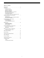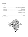
1
Water Conditioning Control System
Dealer Installation, Operation and Maintenance Manual
R&M Water Group
Dealer Dealer Dealer
Technetic Plus Countercurrent 1100
Table of Contents
Introduction . . . . . . . . . . . . . . . . . . . . . . . . . . . . . . . 3
Installation. . . . . . . . . . . . . . . . . . . . . . . . . . . . . . . . 5
Location Selection
Water Line Connection
Drain Line Connection
Brine Line Connection
Brine Tank Overflow Line Connection
Brine Tank and Salt Selection
Connecting the Control
Increasing the Length of the Transformer Cord
Placing Conditioner Into Operation . . . . . . . . . . . . 7
Initial Start-Up
Checking the Brine Draw and Refill Functions
Battery Back-Up Feature
Programming the 1100 Control. . . . . . . . . . . . . . . . 9
Level I Parameters
Level II Parameters
Notes on Technetic Plus Efficiency
Regeneration . . . . . . . . . . . . . . . . . . . . . . . . . . . . . 16
Manual Regeneration
Automatic Regeneration
Reserve Options
Service and Preventive Maintenance . . . . . . . . . . 17
Injector Screen and Injector
Water Meter
Disinfection of Water Conditioners. . . . . . . . . . . . 18
Sodium Hypochlorite 5.25%
Riser Pipe Assembly . . . . . . . . . . . . . . . . . . . . . . . 19
Specifications . . . . . . . . . . . . . . . . . . . . . . . . . . . . 20
Control Valving Identification. . . . . . . . . . . . . . . . 20
Flow Diagrams . . . . . . . . . . . . . . . . . . . . . . . . . . . 21
Pressure Graphs. . . . . . . . . . . . . . . . . . . . . . . . . . . 22
Control Valve Parts List . . . . . . . . . . . . . . . . . . . . 23
Troubleshooting. . . . . . . . . . . . . . . . . . . . . . . . . . . 25
Alarms
Troubleshooting Procedures
2
• Separate Time of Day and Time of Regeneration
Introduction
Settings. The control defaults to a 2:00 a.m. regeneration
time for easy installation, but the installer may set the
regeneration to occur at any time of the day.
The Technetic Plus 1100 Control valve provides sophisticated,
demand-based water conditioning by incorporating a
microprocessor and a water meter to electronically monitor
the amount of water used daily. This fully programmable
control allows you to fine tune the conditioner’s operation to
meet your customer’s application. The Technetic Plus valve
combines design simplicity with reinforced Noryl*
construction to provide an uncommonly reliable appliance.
The inherent reliability of the system means a long life of
efficient, trouble-free water conditioning.
• WQA S-101 Features. The control can be programmed
to freeze the values for salt amount and capacity so the
customer cannot alter them after installation (see
Parameter P18, Table 3.)
• Selectable 12 or 24-Hour Clock. (See Parameter P13.
Table 3.)
• Selectable U.S. or Metric Units of Measure. Use grains
per gallon of hardness, pounds of salt, and kilograins of
capacity for U.S. units. Use milligrams per liter of
hardness, kilograms of salt and kilograms of capacity for
metric units (see Parameter P12, Table 3.)
*Noryl is a trademark of General Electric Co.
Special Features
• Memory Retention. During a power outage, critical
• Selectable Calendar Override. One to thirty days are
operating information in the control’s memory is stored
in a special electronic device. This information includes
the time of day, water usage amounts, daily average
water usage, all programming data and the number of
days since the last regeneration. When power is restored,
the information is returned to the microprocessor and
operation resumes as if an outage never occurred.
available to automatically regenerate the conditioner if
the water usage has not caused a regeneration. The
default value is zero which disables this feature (see
Parameter P14, Table 3.)
• Design Reliability. Solid-state electronics assure many
years of trouble-free performance. The metering system
has only one moving part, the rotating turbine that
measures water usage and generates electrical pulses that
are counted by the microprocessor to determine the need
to regenerate.
• Battery Backup. The non-rechargeable battery backup
feature allows the control to keep track of time and any
water usage for up to 48 hours during a power outage.
• Fully Programmable Regeneration Cycle Times. The
• Guest Cycle. An extra regeneration can be achieved at
control is factory programmed with typical regeneration
cycle times for easy installation. The control allows the
Refill, Rinse, Backwash and Purge cycle times to be set
by the installer to fine tune the conditioner’s operation.
any time by pressing the REGEN button on the
Technetic Plus front panel. It takes just a few minutes for the
regeneration to start. The regeneration process will be
completed in about 1 hour, based on the size of the
system. This feature is beneficial when the customer
expects to use more than the normal amount of water; for
example, guest visits or an extra heavy laundry day.
• Automatic Double Regeneration for Exhausted Resin
Beds. If the water usage exceeds 150% of the system
capacity between regenerations, the control will
automatically call for a second regeneration the next day
even if no water is used. This feature is included to make
sure that an exhausted resin bed is completely recharged.
• Manual Double Regeneration. Back-to-back
regenerations can be run by pressing the REGEN push
button after the first regeneration has been running for at
least one minute.
• Selectable Reserve Options. The control can be
programmed to operate with one of four different reserve
options (see Parameter P15, Table 3.) The options
include starting a regeneration only at a specific time of
day or having an immediate regeneration when the
capacity is exhausted. The control can also have a fixed
reserve which is a percentage of the total system capacity
or a variable reserve which adjusts the reserve depending
upon the water usage patterns of your customer.
3
Superior Design
Superior Operation
• Direct acting system functions independently of water
• Hybrid Distribution System keeps resin compacted and
pressure. No pistons or diaphragms that require a
minimum water pressure to operate.
maximizes salt efficiency.
• Clear aircheck provides viewing of brine draw and refill
• Five-cycle operation provides for down-flow
functions and eliminates the need for an external brine
valve.
conditioned water, soft water refill of the brine tank, upflow brining and slow rinse, up-flow backwash and
down-flow fast rinse.
• Patented proportional brining regenerates only the
exhausted portion of the resin bed for maximum salt
efficiency.
• Valve discs are held closed by water pressure and are
leak tight. Valve seats are in a vertical position, which is
the position least vulnerable to plugging.
• Fewer parts than any control system of comparable
function and most controls of lesser function.
• System operation cannot get out of phase or sequence.
• The valve may be indexed manually without power to
The control always returns to a fixed conditioned water
position after regeneration.
any one of its service or regeneration positions. The
Regeneration Cycle indicator on the cam gear indicates
control valve position.
• Bypass water is automatically available during
regeneration.
• No dynamic seals that could cause leakage through wear
• Soft water is used for brine refill.
or fatigue.
• Control accepts a wide selection of plumbing
connections or modular bypass valves offering complete
versatility and easy plumbing for any installation.
• Drain flow control is built into the valve to control
backwash flow rate. Not included on Model 1130 or
1150FA.
4
Installation
All plumbing must conform to local codes. Inspect the unit
carefully for carrier shortage or shipping damage.
Not in Bypass
In Bypass
Water
Conditioner
Water
Conditioner
Location Selection
The following considerations must be taken into account
when selecting the location for the water conditioning
system.
• Locate the unit as close to a drain as possible.
• If supplementary water treating equipment is required,
make sure that adequate additional space is available.
Locate the brine tank in an accessible place so that salt
can be added easily.
Figure 2
• Do not install any unit closer than 10 feet (3 m) between
Drain Line Connection
the outlet of the conditioner and the inlet of water heater.
Water heaters can transmit heat back down the cold water
pipe into the control valve. Hot water can severely
damage the conditioner. A positive way to prevent hot
water from flowing from a heat source to the conditioner
is to install a check valve in the soft water piping from
the conditioner. If a check valve is installed, make sure
that the water heating unit is equipped with a properly
rated temperature and pressure safety relief valve.
Always conform to local codes.
Ideally located, the unit will be above and not more than 20
feet (6.1 m) from the drain. For such installations, using an
appropriate adapter fitting (not supplied), connect 1/2-inch
(1.3-cm) plastic tubing to the drain line connection of the
control valve.
If the unit is located more than 20 feet (6.1m) from the drain,
use 3/4-inch (1.9-cm) tubing for runs up to
40 feet (12.2 m). Also, purchase appropriate fitting to connect
the 3/4-inch tubing to the 1/2-inch NPT drain connection.
• Do not locate the unit in a area where the temperature
falls below 34oF (1oC) or over
120oF (49oC)
If unit is located where drain line must be elevated, you may
elevate the line up to 6 feet (1.8 m) providing the run does not
exceed 15 feet (4.6 m) and water pressure at the filter is not
less than 40 psi (280 bar). You may elevate an additional 2
feet (61 cm) for each additional 10 psi (70 bar).
• Do not install the unit near acid or acid fumes.
• Do not expose the unit to petroleum products.
Water Line Connection
Where the drain line is elevated but empties into a drain
below the level of the control valve, form a 7-inch
(18-cm) loop at the far end of the line so that the bottom of
the loop is level with the drain line connection. This will
provide an adequate siphon trap.
A bypass valve system must be installed since there are
occasions when the water conditioner must be bypassed for
hard water or for servicing. The most common bypass
systems are the Technetic Plus bypass valves. Figure 1, and
plumbed-in globe valves,
Figure 2. Though both are similar in function, the Technetic Plus
bypass offers simplicity and ease of operation.
Not in Bypass
Where a drain empties into an overhead sewer line, a sinktype trap must be used.
IMPORTANT: Never connect drain line directly into a
drain, sewer line or trap. Always allow an air gap between the
drain line and the wastewater to prevent the possibility of
sewage being back-siphoned into conditioner.
In Bypass
Right Way
Water
Conditioner
Water
Conditioner
Figure 1
Figure 3
5
The power connection is located on the underside of the
control on the left front side. Insert the barrel style
connector into the power plug.
Note: Standard commercial practices have been expressed
here. Local codes may require changes to these suggestions.
Brine Line Connection
2. Plug the wall-mount transformer into an electrical outlet
that is not controlled by a wall-switch.
Install the brine line between the pickup tube in the brine tank
and the 3/8-inch tubing nut on the air check of the control
valve.
Increasing the Length of the Transformer Cord
Note: Make sure that all fittings and connections are tight so
that premature checking does not take place. Premature
checking occurs when the ball in the air check falls to the
bottom before all brine is drawn out of the brine tank. Refer
to the Troubleshooting section in this manual for additional
information.
If it is necessary to extend the length of the transformer cord,
an optional 15-foot (4.6-m) extension cord is available, P/N
1000907, Figure 5 or the cord may be spliced as follows:
1. Strip insulation from wire 5/16 inch (7.87 mm) from wire
end.
2. Insert stripped wire into barrel of connector and crimp.
For best results, crimp twice per wire as shown Figure 6.
Brine Tank Overflow Line Connection
Splice connections or extension wire is not supplied. They are
available at hardware or electrical stores.
In the event of a malfunction, the brine tank overflow
connection directs overflow to the drain instead of spilling on
the floor where it could cause water damage:
1. Locate the fitting hole on the side of the brine tank.
2. Insert the overflow fitting (not supplied) into the tank
and tighten with the plastic thumb nut and gasket as
illustrated in Figure 4.
3. Attach a length of 1/2-inch (1.3-cm) tubing (not
supplied) to the fitting and run to the drain.
Figure 5
Note: Do not elevate the overflow line higher than
3 inches (7.6 cm) below the bottom of the overflow fitting.
Do not tie into the drain line of the control unit. The overflow
line must be a direct, separate line from the overflow fitting
to the drain, sewer, or tub. Allow an air gap as the drain line
connection (Figure 3).
Overflow Fitting
Installed
Brine Tank
Figure 6
Connect 1/2-in (1.3-cm)
I.D. Tubing or Hose and
Run to Drain
There is also a 15-foot splitter cord (not shown) to use one
transformer to operate two 12-volt controls,
P/N 1034264.
Figure 4
Placing Conditioner into Operation
Brine Tank and Salt Selection
Initial Start-Up
The Technetic Plus is designed to operate with a wet salt system.
Do not use a grid plate (salt shelf) in the brine tank. High
quality salt is recommended. Do not use block salt.
After the water conditioning system is physically installed,
we recommend that the conditioner be disinfected before it is
used to treat potable water. Refer to the Disinfection of
Water Conditioners section in this manual. Complete the
following steps to place the conditioner into operation:
Connecting the Control
1. Connect the control to the 12-volt wall transformer cable.
1. Remove the control valve cover by grasping each side of
6
the cover at the bottom, towards the back. Spread the sides
apart slightly and lift off. Figure 7.
Figure 9
6. Open the water supply valve very slowly to
approximately the 1/4-open position, and slowly fill the
resin tank with water.
Figure 7
2. Disconnect power to the control by unplugging the wall
transformer or removing the power wire from the bottom
of the control.
Note: If the water supply valve is opened too rapidly or too
far, resin may be lost. In the BACKWASH position, you
should hear air escaping slowly from the drain line.
3. Turn off the water supply and place the bypass valve(s)
in the “not in bypass” position.
7. When all the air is purged from the resin tank (water
begins to flow steadily into the drain), slowly open the
main supply valve all the way. Allow the water to run
into the drain until clear. Turn off the water supply and
wait for about five minutes to allow all trapped air to
escape from the tank. Open the water supply valve
slowly to the full open position.
4. Press down on the top of the drive gear to disengage the
cam gear, Figue 8.
8. Press down on the top of the drive gear to disengage the
cam gear, Figure 8.
9. With the cam gear disengaged, rotate the cam gear
counterclockwise to just before the Service position,
Figure 9. Connect power to the control and allow the
motor to drive the cam gear to the Service position.
When the cam gear reaches the Service position, the
motor will stop.
Figure 8
Checking the Brine Draw and Refill Functions
1. Disconnect power to the control by unplugging the wall
transformer or unplugging the power cord from the bottom
of the control.
5. With the cam gear disengaged, rotate the cam gear
counterclockwise to the Backwash position,
Figure 9.
2. Press down on the top of the drive gear to disengage the
cam gear. Figure 8.
3. With the cam gear disengaged, rotate the cam gear
counterclockwise to the Refill position until the air
check, Figure 10, fills with water, and water flows
through the brine line into the brine tank. Do not run for
more than three minutes.
4. Press down on the drive gear, and rotate the cam gear
counterclockwise to the Draw/Rinse position. Check that
water is being drawn from the brine tank. The water level
in the brine tank will recede very slowly. Observe the
water level for at least one minute. If the water level does
7
3. The battery connector has special snaps which allow the
battery to be installed properly. Press the new battery
firmly into the snaps.
not recede, if it goes up, or if air enters the transparent air
check chamber and the ball falls and seats, refer to the
Troubleshooting section in this manual.
4. Place the battery into the pocket.
5. When water is being drawn from the brine tank, press
down on the drive gear and rotate the cam gear
counterclockwise to just before the Service position,
Figure 10. Connect power to the control and allow the
motor to drive the cam gear to the Service position, the
motor will stop. Run cold water from a nearby faucet
until the water is clear and soft.
5. Replace the valve cover.
Air Check
Figure 10
Battery Back-Up Feature
The Technetic Plus 1100 is supplied with a battery operation
feature allowing the control to continue to monitor water flow
and maintain the proper time of day during short power
outages. The control uses a standard 9-volt battery (not
supplied).
During a power outage, the display will be turned off and the
motor will not run, but the control will continue to totalize
water flow. If power is out and a regeneration is needed, the
regeneration will be delayed until power is restored. If power
is lost during a regeneration, the control will resume the
regeneration when power is restored.
A typical new 9-volt alkaline battery will provide
approximately two days of power for the control. Older
batteries or those exposed to temperatures over
75oF (23.9oC) will provide power for a shorter length of time.
The control can be operated without a battery, but the control
will not measure water usage or time while the power is off.
The control will save all important operating information and
programming data during a power outage. No
reprogramming is necessary.
Note: It is recommended that the battery be replaced every
year or after any extended power outage.
To install a battery:
1. Remove the cover of the Technetic Plus 1100.
2. The battery pocket is located in the upper left corner of
the control.
8
Programming the Technetic Plus 1100 Control
Figure 11
•
•
•
•
This section covers all aspects of programming the control.
The control is shipped from the factory with default values
for most parameters. These default values will result in a
system capacity of 100 gallons
(1 cubic meter). While the control may operate with these
values, the following parameters must be changed to meet the
actual operating conditions and achieve maximum system
capacity and salt efficiency:
•
•
•
•
•
•
•
•
Time of Regeneration
Hardness
Salt Amount
Capacity
If you continue to press the down arrow ( ↓ ) button, the
parameters start over with Time of Day. Pressing the up arrow
( ↑ ) button displays the parameters in reverse order. Refer to
Table 1 for description of these parameters and available
ranges for each parameter.
Time of Day
Time of Regeneration
Press the SET button and the far right digit of the display
starts flashing. If you want to change this number, press the
up arrow ( ↑ ) button to increase the number or the down
arrow ( ↓ ) button to decease the number. To skip the number
without changing, press the left arrow ( ← ) button. When
you reach the far left digit, pressing the left arrow ( ← ) button
will return you to the far right digit.
Hardness
Salt Amount
Capacity of the Unit
Refill Controller Value
Brine Draw Rate
Slow Rinse Time
Note: If you press and hold either the up arrow ( ↑ ) button or
the down arrow ( ↓ ) button for more than one second, the
flashing number will increment or decrement at the rate of 10
counts per second.
Note that some parameters have a single unit of measure
option such as the Slow Rinse Time which is only entered in
minutes. Other parameters have dual units such as Salt
Amount which can be entered in pounds or kilograms. To
select which units are active, look for a comment in the
NOTES column of Tables 1 and 3. It will reference another
parameter that selects which units are active. For example,
parameter P12 (Table 3) selects U.S. units if it is set to “0” and
metric if it is set to “1”.
When the number is correct, press the left arrow ( ← ) button.
The far right digit stops flashing and the next digit to the left
starts flashing. You can only change the flashing number.
Continue changing numbers until you reach the desired
setting. Press the SET button. The numbers stop flashing and
the control accepts the new setting. After approximately 30
seconds, the control starts alternating the display between
Time of Day and Capacity.
Level I Parameters (Table1)
Level I Parameters are identified as those that have an LED
indicator on the front panel. The green indicator illuminates
next to the name of the active control setting. The end user
has access to all of these parameters which are explained in
the Technetic Plus Operation and Maintenance Manual. In
general, pressing the down ( ↓ ) arrow button displays the
Level I Parameters in the following order:
Note: If the new setting is not accepted because it was outside
the allowable range, the old value will be displayed.
Time of Day
Press the SET button. The display will show the Time of Day
with the minutes digit blinking. If you want to change this
number, press the up arrow ( ↑ ) button to increase the number
• Time of Day
9
or the down arrow ( ↓ ) button to decrease the number. To skip
the number without changing, press the left arrow ( ← )
button. The first number stops flashing and the next number
starts flashing. You can only change the flashing number.
When you have reached the far left digit, pressing the left
arrow ( ← ) button returns you to the far right digit. Continue
changing numbers until you reach the desired setting. Press
the SET button again to enter the value.
Capacity
Time of Regeneration
Note: If the calculation for the system capacity exceeds 9999
gallons (99.99 cubic meters) (P5, Capacity, divided by P3,
Hardness), the control will display 9999 (99.99) for capacity
until the water usage has dropped the remaining capacity
below that number. When water is flowing through the
system, the colon in the Time of Day display will blink.
Capacity is the next value displayed and is expressed in
kilograins (kilograms). Refer to Table 2 for the capacity
setting that corresponds to the resin bed volume and salt
amount. The default value is
1.0 kilograin (0.1 kilograms). To change, press the SET
button and enter a new value. Any value between
0.1 and 140 kilograins (0.01 and 14.00 kilograms) is allowed.
The next value displayed is the Time of Regeneration, it is
similar to Time of Day programing. It has the default value
of 2:00 a.m. If 2:00 a.m. is acceptable, press the down arrow
( ↓ ) button. If this is not acceptable, press the SET button and
change the numbers. Press the SET button again to enter the
value.
At this time, all of the Level I parameters are programed. The
display will alternate between the Time of Day and Capacity
if no keys are pressed for
30 seconds. The Capacity value displayed is the volume
remaining in gallons (cubic meters for metric) before a
regeneration is needed.
Hardness
Hardness is the next value displayed. This value is the water
hardness expressed in grains per gallon (milligrams per liter).
The default value is
10 grains/gallon (100 milligrams per liter). If this is not
acceptable, press the SET button and enter a new value. Any
value between 3 and 250 grains per gallon (30 and 2500
milligrams per liter) is allowed. Press the SET button again
to enter the new value.
To complete the initial programming of the Technetic Plus 1100,
proceed to the Level II Parameters, page 13.
Salt Amount
Salt Amount is the next value displayed. The default value for
Salt Amount is 6 pounds (2.5 kilograms) of salt. Refer to
Table 2, and select a salt dosage based on resin bed volume
and desired system capacity.
Note: This is the total amount of salt for a regeneration,
not pounds per cubic foot. If 6 pounds is not acceptable,
press the SET button and change the value. If 6 pounds is
acceptable, press the down arrow ( ↓ ) button.
10
Table 1 - Level 1 Programming Parameters
Parameter
Description
Time of day
P1
AM or PM
Name
Range of Values
1:00 to 12:59
00:00 to 23:59
1:00 to 12:59 AM
or PM
00:00 to 23:59
Minimum
Increments
Default
Units of
Measure
1
None
Hour:minute
1
2:00 AM
Hour:minute
P2
Time of day of
regeneration
P3
Hardness of
Water
3 to 250
30 to 2500
1
10
10
100
Grains/gallon
milligrams/L
P4
Salt amount
0.5 to 99.5
0.1 to 25.5
0.5
0.1
6
2.5
Pounds
Kilograms
P5
Capacity of
unit
0.1 to 140.0
0.01 to 14.00
0.1
0.01
1.0
0.1
Kilograins
Kilograms
11
Notes
Range depends on value selected for
P13. Enter the current time.
Range depends on value selected for
P13. Skip this parameter to accept
the default or enter a new time.
Unit of measure depends on value
selected for P12. Test water hardness
(compensated hardness) and enter
that value.
Unit of measure and default depends
on value selected for P12. Select salt
amount from Table 2 and enter that
value.
Unit of measure depends on value
selected for P12. Enter the unit
capacity. Refer to Table 2.
Table 2 - Technetic Plus 1100 System Capacity Inputs (Kilograins)
Salt
Setting
(pounds)
RESIN VOLUME (cubic feet)
0.50
0.75
1.00
2.5
7.5
9.0
10.5
1.25
1.50
2.00
2.25
2.50
3.00
3.25
3.50
3.0
8.4
9.9
11.4
12.9
3.5
9.3
10.8
12.3
13.8
4.0
9.9
11.7
13.2
14.7
16.2
4.5
10.2
12.6
14.1
15.6
17.1
5.0
10.5
13.5
15.0
16.5
18.0
21.0
5.5
10.8
14.4
15.9
17.4
18.9
21.9
23.4
6.0
11.1
14.9
16.8
19.8
22.8
24.3
25.8
25.8
6.5
15.2
17.7
19.2
20.7
23.7
25.2
26.7
7.0
15.5
18.6
20.1
21.6
24.6
26.1
27.6
7.5
15.8
19.5
21.0
22.5
25.5
27.0
28.5
31.5
8.0
16.1
19.8
21.9
23.4
26.4
27.9
29.4
32.4
33.9
8.5
16.4
20.1
22.8
24.3
27.3
28.8
30.3
33.3
34.8
36.3
9.0
16.7
20.4
23.7
25.2
28.2
29.7
31.2
34.2
35.7
37.2
9.5
17.0
20.7
24.5
26.1
29.1
30.6
32.1
35.1
36.6
38.1
10.0
17.3
21.0
24.8
27.0
30.0
31.5
33.0
36.0
37.5
39.0
10.5
21.3
25.1
27.9
30.9
32.4
33.9
36.9
38.4
39.9
11.0
21.6
25.4
28.8
31.8
33.3
34.8
37.8
39.3
40.8
11.5
21.9
25.7
29.4
32.7
34.2
35.7
38.7
40.2
41.7
12.0
22.2
26.0
29.7
33.6
35.1
36.6
39.6
41.1
42.6
12.5
22.5
26.3
30.0
34.5
36.0
37.5
40.5
42.0
43.5
13.0
22.8
26.6
30.3
35.4
36.9
38.4
41.4
42.9
44.4
13.5
26.9
30.6
36.3
37.8
39.3
42.3
43.8
45.3
14.0
27.2
30.9
37.2
38.7
40.2
43.2
44.7
46.2
14.5
27.5
31.2
38.1
39.6
41.1
44.1
45.6
47.1
15.0
27.8
31.5
39.0
40.5
42.0
45.0
46.5
48.0
15.5
28.1
31.8
39.3
41.4
42.9
45.9
47.4
48.9
16.0
28.4
32.1
39.6
42.3
43.8
46.8
48.3
49.8
16.5
32.4
39.9
43.2
44.7
47.7
49.2
50.7
17.0
32.7
40.2
44.1
45.6
48.6
50.1
51.6
17.5
33.0
40.5
44.3
46.5
49.5
51.0
52.5
18.0
33.3
40.8
44.6
47.4
50.4
51.9
53.4
18.5
33.6
41.1
44.9
48.3
51.3
52.8
54.3
19.0
33.9
41.4
45.2
48.9
52.2
53.7
55.2
19.5
45.5
49.2
53.1
54.6
56.1
20.0
45.8
49.5
54.0
55.5
57.0
Ultra High, greater than 4000 grains per pound
High, 3500 - 4000 grains per pound
Standard, Less than 3500 grains per pound
12
Table 3 - Level II Programming Parameters
Parameter
Name
Description
Range of
Values
Minimum
Increments
Default
Units of
Measure
1 to 99
1
33
1 to 99
1
25
N/A
N/A
N/A
N/A
P8
Refill
Controller
Brine draw
value
Not used
P9
Backwash time
3 to 30
1
14
Minutes
P10
Slow Rinse
time
8 to 125
1
40
Minutes
P11
Fast Rinse time
2 to 19
1
4
Minutes
P12
Units of
measure
0 to1
1
0
P13
Clock mode
0 to 1
1
0
P14
Calendar
override
0 to 30
1
0
P15
Reserve type
0 to 3
1
0
P16
Fixed reserve
capacity or
initial average
value
0 to 70
1
30
P17
Operation type
0 to 1
1
1
P18
Salt/Capacity
change lock
out
0 to 1
1
0
P19
Factory
defaults
0 to 3
1
9
P6
P7
13
Days
Percent of
capacity
Notes
Select value from Table 4 and enter that
number.
Select Brine Draw value from Table 4 and
enter that number.
N/A
Skip this parameter to accept the default
or enter a value.
Select Time from Table 4 and enter that
value.
Skip this parameter to accept the default
or enter a value.
0 = U.S., 1 = metric. Skip this parameter
to accept U.S. or enter
1 for metric.
0 = 12-hour clock, 1 = 24-hour clock.
Skip this parameter for a 12-hour clock or
enter 1 for a 24-hour clock.
0 = no calendar override. Skip this
parameter for no calendar override or
enter a value.
0 = variable reserve, 1 = fixed reserve, 2 =
variable reserve with immediate regen, 3
= fixed reserve with immediate regen.
Skip this parameter to accept the default
or enter a different reserve type.
Description depends on the value entered
for P15. Skip this parameter to accept the
default or enter a different value.
0 = Not used, 1 = 5 cycle counter current,
partial salting.
0 = none, 1 = salt/capacity change locked
out. Skip this parameter to accept the
default or enter 1 to lock out salt/capacity
change.
Loads in factory default values.
Do not change this parameter.
Level II Parameters
reach P19, the display will go back to P1.
When the parameter number you want to change is displayed,
press the left arrow ( ← ) button to display the data assigned
to that parameter. Press the SET button and the far right digit
on the display starts flashing. If you want to change this
number, press the up arrow ( ↑ ) button or the down arrow (
↓ ) button. To skip the number without changing, press the
left arrow button. When the number is correct, press the SET
button. The numbers stop flashing and the control accepts the
new setting. If the new setting was not accepted, the display
will show the previous setting. Refer to Table 3 for allowable
values for that parameter.
The programming in Level II is critical to the
operation of the Technetic Plus 1100 Control.
Refill control value P6, brine draw value P7, and slow rinse
time P10 must be programmed according to conditioner
system size using Table 4. Other programming parameters in
Level II can be used to increase the efficiency of the water
conditioning system.
The Operating and Maintenance Manual for this product does
not mention these parameters, so the end user does not
normally have access to these values. To access Level II
Parameters, simultaneously press and hold the down arrow (
↓ ) and up arrow ( ↑ ) button for three seconds.
To change or view other parameters, press the left arrow ( ←
) button to have the display show “P” numbers. Now use the
up arrow ( ↑ ) button or the down arrow ( ↓ ) button to move
to the parameter number you wish to change.
If the control was alternating between Time of Day and
Capacity when the above button sequence is entered, the
display shows P1. If a different Level I Parameter was
displayed, the display shows the “P” number for that
parameter. Refer to Table 3 to find the “P” number associated
with each parameter.
To exit the Level II programming mode, simultaneously press
and hold the down arrow ( ↓ ) and up arrow ( ↑ ) buttons for
three seconds, or wait 30 seconds, without pressing a button.
The control starts alternating the display between Time of
Day and Capacity.
Use the up arrow ( ↑ ) button or the down arrow ( ↓ ) button
to move from one parameter to the next. The display cycles
through the ”P” numbers shown in Tables 1 and 3. When you
Table 4 - Technetic Plus System Sizes
Tank Sizes
Resin Volume
Inches
Metric
Ft3
Liters
Refill
Controller
Brine Draw
Value
Slow Rinse
Time
7x35
18x89
0.50
15
14
9
67
7x40
18x101
0.50
15
14
9
67
8x40
21x101
0.75
21
14
7
83
8x44
21x112
0.75
21
14
7
83
9x35
23x89
0.75
21
33
9
70
9x48
23x122
1.00
28
33
9
94
10x35
26x89
1.00
28
33
15
53
10x44
26x112
1.25
35
33
15
67
10x47
26x119
1.25
35
33
15
67
10x54
26x137
1.50
44
33
15
80
12x48
30x122
2.00
56
33
16
83
12x52
30x132
2.25
64
33
16
94
13x54
33x137
2.50
71
33
18
107
14x47
35x119
2.50
71
33
21
60
14x65
35x165
3.00
85
33
21
72
14x65
35x165
3.25
91
33
21
78
14x65
35x165
3.50
99
33
21
84
14
Refill Control
this is set to the correct value before entering any data for
parameters P3, P4, or P5.
Each Technetic Plus control valve is supplied with a
refill/backwash control based on the water conditioner
system size. To verify that the correct control is installed,
check the number located on the face of the refill/backwash
control, Figure 12. This number should match the diameter of
the resin tank. To operate correctly, the control must have
parameter P6 programmed to the correct refill controller
value. The default value in P6 is 33. Find the correct value in
Table 4. If 33 is not correct, press the SET button and enter
the correct value from Table 4.
• Parameter P13 selects the clock display mode. If the 12hour mode is selected, a PM indicator is used. If the 24hour mode is selected, the PM indicator is not used.
• Parameter P14 is used to set the calendar override
feature. The default value is zero. If set to zero, the
feature is disabled. Refer to Calendar Override, page
16 for more information on the calendar override feature.
• Parameter P15 selects a variable reserve type, 0 to 3. For
more information on reserve options, refer to Page 17.
• Parameter P16 is used to calculate the initial average
Note: Do not overtighten the plastic cap. Seat the cap lightly
into position. Overtightening may cause breakage of the
plastic cap that may not be immediately evident.
daily water usage values. The control multiplies the total
capacity by the percentage entered for Parameter P16
and uses that value as the initial average daily usage for
each day of the week until water usage establishes new
averages. The default is set for 30% of the capacity. In
most installations this is acceptable.
• Parameter P17 has been preset to 1. Do not change this
setting. P17 must be set to 1 for 1100 operation.
Improper regenerations will occur if P17 is set to 0.
• Parameter P18 allows the installer to lock the Salt
Amount and Capacity values so they cannot be changed.
When Parameter 18 is set to 1, those two settings can
only be viewed when the control is in the Level II mode.
The settings will be skipped when the control is in the
Level I mode. When Parameter 18 is set to zero, the Salt
Amount and Capacity can be viewed and changed in
either Level I or Level II.
Figure 12
Brine Draw Value
Brine draw value P7 is used by the control to calculate the
brine draw time. The brine draw value is an estimate of the
flow rate of brine through the injector. This value varies with
injector size and conditioner system size. The default value in
P7 is 25. Refer to Table 4 and find the correct brine draw
value for your conditioner system. Press the SET button and
enter a new brine draw value from Table 4.
• Parameter P19 is used at the factory to enter default
values. This parameter does not need to be changed.
Using this parameter will erase the values for all other
parameters and replace them with default values.
Improper regenerations will occur if P19 is set to a 0
or 3. P19 should be set on default number 9.
• The control does not use parameter P8. No entry is
needed for this parameter.
• Parameter P9 is used to set the backwash time in minutes.
The default in P9 is 14 minutes. If a different backwash
time is desired, press the SET button and enter a new
value.
Slow Rinse Time
Parameter P10 determines the slow rinse time, which is based
on conditioner system size. The default value for P10 is 40
minutes. Refer to Table 4 to find the correct slow rinse time
for your conditioner system. Press the SET button and enter
a new value for P10.
• Parameter P11 determines the fast rinse time. The default
value is 4 minutes. If a different fast rinse time is desired,
press the SET button and enter a new value.
• Parameter P12 selects the units of measure. Be sure that
15
Notes on Technetic Plus Efficiencies
applications with working pressure above 60 psi, remove the
“low pressure” injector and install an alternate “high
pressure” injector. The injectors are coded according to size
by the number of “bumps” molded onto the end of the
injector. Refer to Table 5 to find the correct injector based on
tank diameter and water pressure. To order replacement
injectors use the 7-digit part numbers indicated.
In order to consistently achieve the system capacities and salt
efficiencies listed in Table 2, it may be necessary to change
the injector assembly supplied with the Technetic Plus. Each
Technetic Plus control valve is supplied with a standard “low
pressure” injector assembly based on system tank diameter.
This injector assembly is intended for system applications
with working water pressures below 60 psi. For system
Table 5 Injector Selection
Resin Tank Diameter, Inches (centimeters)
Water Pressure
20 to 60 psi
(138 to 414 bar)
61 to 120 PSI
(420 to 827 bar)
7 (17.8)
8 (20.3)
9 (22.8)
10 (25.4)
12 (30.5)
13 (33)
14 (35.5)
2
1032984
3
1032979
4
1032977
5
1032980
6
1032982
7
1032981
8
1032983
1
1032976
2
1032984
3
1032979
4
1032977
5
1032980
6
1032982
7
103281
Regeneration
Time of Day and Regen Time Remaining.
When the control begins a regeneration, the display will
alternate between Time of Day and Regen Time Remaining.
The Regen Time Remaining is shown in minutes. The control
will start and stop an internal motor which drives the cam
gear through the various regeneration positions. The control
uses the information entered in the parameters shown in Table
3 to determine how long each part of the cycle should last.
Automatic Regeneration
There are two ways to have the control automatically initiate
a regeneration: calendar override or normal metered water
usage.
Calendar Override
This feature is set in parameter P14. It can be set for
1 to 30 days. If it is set to zero, this feature is disabled. When
this feature is active, the control keeps track of the number of
days since the last regeneration and when that number equals
the value set in P14, a regeneration is automatically started at
the Time of Regeneration set in P2.
If power fails during a regeneration cycle, the cycle
completes normally when the power is restored.
Note: The REGEN button is only active when the display is
alternating between Time of Day and Capacity. When
programming Level I or II parameters, the REGEN button is
not active.
Normal Metered Water Usage
The Regen Time Remaining in regeneration will continue to
count down until the cam gear reaches the Service position.
The control compares the water usage to the calculated
volume capacity of the system. The control uses the Capacity
parameter P5 divided by the Hardness parameter P3 to
calculate the volume capacity of the system. It also uses a
reserve value to determine if a regeneration is necessary. If
the water usage since the last regeneration is greater than the
system capacity minus the reserve, a regeneration is needed.
Manual Regeneration
To initiate a manual regeneration, press the REGEN button.
This button is located on the front of the control. When you
press the REGEN button, the control performs a full
regeneration of the conditioner.
Note: If the water usage exceeds 150% of the system capacity
between regenerations, the control will automatically call for
a second regeneration the next day even if no water is used.
This feature is included to make sure that an exhausted resin
bed is completely recharged.
If you press this button again more than one minute after
regeneration begins, but before the regeneration is
complete, a second regeneration will start when the first
regeneration is finished.
The display will freeze and only show the Regen Time
Remaining as an indication that the second regeneration will
be performed. When the first regeneration is complete, the
second one will begin and the display will alternate between
Reserve Options
There are two types of reserve options for this control: fixed
reserve and historical water usage pattern. They are selected
16
silicone lubricant and reinstall the control into the valve.
with parameter P15.
5. Using a screw driver, unscrew and remove the injector
screen and injector cap.
Fixed Reserve
When the fixed reserve is selected, the control multiplies the
maximum system capacity by the percent value set in
parameter P16 and uses the result as a reserve.
6. Clean screen using a fine brush, flush until clean.
7. Using a needle nose pliers, pull injector straight out.
Water Usage Pattern
8. Flush water into the injector screen recess of the valve
body to flush debris out through the injector recess.
The other reserve option allows the control to adjust the
reserve based upon the historical water usage pattern of the
system. The control keeps track of the water usage for each
day of the week and uses that day’s average usage multiplied
by 1.2 as the reserve for that day. Every day at the Time of
Regeneration, the control recalculates the day’s average
water usage. If less than 10% of a day’s average water usage
is used, the control will not change the day’s average. If more
than twice the day’s average is used, the control uses the
actual usage in the reserve calculation.
9. Clean and flush the injector.
10. Lubricate the O-rings on the injector, injector cap and
injector screen with silicone lubricant.
11. Reinstall the injector, injector cap and injector screen. Do
not overtighten the plastic cap.
12. Rotate the cam gear counterclockwise to a position
between Purge and Service, then slowly open the water
supply valve or return the bypass valve(s) to the Service
position.
Since a new installation has no history of water usage, the
control multiplies the percent of capacity value set in
parameter P16 by the total system capacity to determine
starting average for each day of the week. The factory set
default value for P16 is 30 which means that 30% of the total
system capacity is used for the starting average for each day.
13. Reconnect the electrical power to the unit. The cam gear
will rotate until the switch lever opens, turning off the
drive motor in the Service position.
14. Reset the time of day and reinstall the control valve.
cover.
Program parameter P15 is also used to select whether the
control waits until the Time of Regeneration set in parameter
P2 to start a regeneration, or if the control should begin a
regeneration immediately when the capacity remaining is less
than the reserve.
Water Meter
In rare instances, the turbine wheel of the water meter can
collect small particles of oxidized iron, eventually preventing
the wheel from turning.
Service and Preventative Maintenance
If the flow indicator light does not blink when conditioned
water is flowing from the unit, it is an indication that the
turbine wheel is not turning.
Injector Screen, Injector and Refill/Backwash
Control
1. Disconnect electrical power supply to the unit.
All maintenance items are located on the lower right side of
the valve. See Figure 12.
2. Shut off the water supply or put the bypass valve(s) into
bypass position.
Inspect and clean the brine tank and filter screen on end of
brine pickup tube once a year or when sediment appears in the
bottom of the brine tank.
Clean the injector, injector screen and refill/backwash control
once a year as follows:
1. Disconnect electrical power to the unit.
2. Shut off the water supply or put bypass valve(s) into
bypass position.
3. Relieve resin tank pressure:
A. Remove control valve cover.
B. Press down on the top of the drive gear to disengage
the cam gear.
C. With the cam gear disengaged, rotate the cam gear
counterclockwise to the Backwash position.
4. Using a screwdriver, unscrew and remove the
refill/backwash control. Clean and flush the control with
a strong stream of water. Lubricate the O-rings with
17
Disinfection of Water Conditioners
3. Relieve resin tank pressure:
A. Remove control valve cover.
The construction materials of the water conditioning system
do not support bacterial growth or contaminate the water
supply. However, we recommend that the conditioner be
disinfected after installation and before the conditioner can
become fouled with organic matter during normal usage or
with bacteria from the water supply. Periodic disinfection is
recommended for all conditioners. Use one of the following
methods of disinfection based on operating conditions, style
of conditioner, type of resin, and disinfectant available.
B. Press down on the top of the drive gear to disengage
the cam gear.
C. With the cam gear disengaged, rotate the cam gear
counterclockwise to the Backwash position.
Check that there is no water flow through the drain line
before performing service or preventative maintenance.
4. Disconnect the water conditioner from the plumbing.
5. Using needle-nose pliers, remove the outer gland and the
turbine wheel from the outlet of the valve. Generally it
will not be necessary to remove the inner gland.
Sodium Hypochlorite 5.25%
Sodium Hypochlorite solutions can be used with polystyrene
resin, synthetic gel zeolite, greensand, and bentonites and re
available under trade names such as Clorox*. Adjust the
dosage if stronger commercial solutions are used.
6. Clean all iron deposits and/or debris off the turbine
wheel. Excessive accumulation of iron may be removed
from the components with a solution of sodium
hydrosulfite (or sodium bisulfite). Rinse the components
thoroughly in clean water after using the iron removal
solution.
The recommended dosage for 5.25% solutions is:
• Polystyrene resin: 1.2 fluid ounces per cubic foot.
• Non-resinous exchangers: 0.8 fluid ounce per cubic foot.
7. Flush accumulated iron deposits and/or debris from the
inside of the valve outlet.
Complete the following steps to disinfect the conditioner:
Add the sodium hypochlorite solution to the brine well of the
brine tank. Make sure that the brine tank has water in it so the
solution is carried into the conditioner. Proceed with normal
regeneration. Refer to the Manual Regeneration section.
8. Reinstall the turbine wheel into the outlet side of the
valve, being certain that the turbine wheel shaft is
carefully seated into the bearing of the inner gland.
9. Carefully reinstall the outer gland into the outlet side of
the valve. Check turbine rotation.
*Clorox is a trademark of the Clorox Co.
10. Reconnect the water conditioner to the plumbing and
follow Initial Start-up, page 7.
11. Open a downstream faucet (conditioned water) and
check to be certain that the flow indicator (colon) is
blinking.
Turbine Wheel
Outer Gland
Inner Gland
Turbine Assembly
Figure 13
18
Riser Pipe Assembly
The dimensions provided here will make it easy for
assemblers to cut the riser pipe when building the Technetic Plus
softeners.
1 in (25.4 mm)
2 in (51 mm)
Solvent Bond
1 in (25.4 mm)
Solvent Bond
Resin Bed
Figure 14
Outside Diameter
Inner Pipe
1.050 ± 0.004 in
26.67 ± 0.10 mm
Outer Pipe
1.315 ± 0.005 in
33.40 ± 0.13 mm
Wall Thickness
Inner Pipe
0.060 + 0.020 in
- 0.000 in
1.52
+ 0.51 mm
- 0.00 mm
Outer Pipe
0.063 + 0.020 in
- 0.000 in
1.60 + 0.51 mm
- 0.00 mm
19
Specifications
Hydrostatic Test Pressure . . . . . . . . . . . . . . . . . . . . . . . . . . . . . . . . . . . . . . . . . . . . . . . . . . . . . . . . . . . . . . . . . . .300 psi (2069 bar)
Working Pressure. . . . . . . . . . . . . . . . . . . . . . . . . . . . . . . . . . . . . . . . 20 to 120 psi (138 to 827 bar), 100 psi maximum in Canada
Voltage . . . . . . . . . . . . . . . . . . . . . . . . . . . . . . . . . . . . . . . . . . . . . . . . . . . . . . . . . . . . . . . . . . . . . . . . . . . . . 102 to 132 VAC, 60 Hz
Current. . . . . . . . . . . . . . . . . . . . . . . . . . . . . . . . . . . . . . . . . . . . . . . . . . . . . . . . . . . . . . . . . . . . . . . . . . . . . . . . . . . . . . . . . . . 50 mA
Operating Temperature . . . . . . . . . . . . . . . . . . . . . . . . . . . . . . . . . . . . . . . . . . . . . . . . . . . . . . . . . . . . . . . 34o to 120oF (1o to 49oC)
Humidity . . . . . . . . . . . . . . . . . . . . . . . . . . . . . . . . . . . . . . . . . . . . . . . . . . . . . . . . . . . . . . . . . . 10% to 100%, condensing allowed
Transformer . . . . . . . . . . . . . . . . . . . . . . . . . . . . . . . . . . . . . . . . . . . . . . . .Wall-mount with plug options, rated for indoor use only
Water Flows. . . . . . . . . . . . . . . . . . . . . . . . . . . . . . . . . . . . . . . . . . . . . . . . . . . . . . . . . . . . . . Accurate over range of 0.5 to 23 gpm
Pressure Tank Thread . . . . . . . . . . . . . . . . . . . . . . . . . . . . . . . . . . . . . . . . . . . . . . . . . . . . . . . . . . . . . . . . . . . . . 2 1/2 inch - 8 male
Brine Line Connection . . . . . . . . . . . . . . . . . . . . . . . . . . . . . . . . . . . . . . . . . . . . . . . . . . . . . . . . . . . . . . . . . . . 3/8-inch Tubing Nut
Drain Line Thread . . . . . . . . . . . . . . . . . . . . . . . . . . . . . . . . . . . . . . . . . . . . . . . . . . . . . . . . . . . . . . . . . . . . . . . . 1/2-inch NPT male
Service Connections . . . . . . . . . . . . . . . . . . . . . . . . . . . . . . . . . . . . . . . . . . . . . . . . . . . . . . 1-inch NPT or BSPT brass pipe adapter
3/4-inch BSPT brass pipe adapter
1-inch or 3/4-inch copper tube adapter
22-mm or 28-mm copper tube adapter
1-inch or 3/4-inch PVC tube adapter
25-mm PVC tube adapter
1-inch or 3/4-inch NPT plastic pipe adapter
1-inch or 3/4-inch BSPT plastic pipe adapter
Bypass Valve . . . . . . . . . . . . . . . . . . . . . . . . . . . . . . . . . . . . . . . . . . . . . . . . . . . . . . . . . . . . . . . . . . . . . . . . . . . . . . . . . . . . Optional
Valve Disc Identification
Disc 6 - Lower Drain
Disc 5 - Outlet
Disc 3 - Inlet
Disc 2 - Upper Drain
Disc 4 - Bypass
Disc 1 - Brine
Disc 7 - Center Distributor
20
Flow Diagrams
21
Pressure Loss Characteristics
22
1100 Valve Body
23
Part
Part
Code
No.
Qty.
Code
No.
1
1034448
Valve Body Assembly
Description
1
16
1040717
Valve Disc Kit
1
2
1034347
Motor Drive Assembly, 60 Hz
1
17
1001580
Valve Disc Spring
11
1034346
Motor Drive Assembly, 50 Hz
1
18
1034360
Top Plate Assembly with Springs
1
3
1034424
Control Assembly, 1000i , English
1
19
1032416
Air Check Kit
1
4
1034362
Cam Gear, 1100 English
1
20
1032250
Drive Gear
1
1034363
Cam Gear, 1100 Symbols
1
21
1006002
Screw, 8-18 x 1-1/2 inch
2
5
1032881
Bracket
1
22
1031118
Spring
1
6
1005001
Screw, 10-32 x 1/2 inch
1
23
1006093
Top Plate Screw
17
7
1033670
Turbine Group
1
24
1033998
Black Cover
1
8
1034337
7-inch Brine/backwash Control
1
1033996
Beige Cover
1
25
Description
Qty.
1034338
8-inch Brine/backwash Control
1
1001606
3/4-inch Copper Tube Adapter Kit
1
1034339
9-inch Brine/backwash Control
1
1001670
1-inch Copper Tube Adapter Kit
1
1034340
10-inch Brine/backwash Control
1
1001608
22-mm Copper Tube Adapter Kit
1
1034341
12-inch Brine/backwash Control
1
1001609
28-mm Copper Tube Adapter Kit
1
1034342
13-inch Brine/backwash Control
1
1001613
3/4-inch CPVC Tube Adapter Kit
1
1034343
14-inch Brine/backwash Control
1
1001614
1-inch CPVC Tube Adapter Kit
1
9
1032988
Injector Screen Assembly
1
1001615
25-mm CPVC Tube Adapter Kit
1
10
1032976
Injector Assembly, 1 Bump
1
1001769
3/4-inch NPT Plastic Pipe Adapter Kit
1
1032984
Injector Assembly, 2 Bumps
1
1001603
1-inch NPT Plastic Pipe Adapter Kit
1
1032979
Injector Assembly, 3 Bumps
1
1001604
3/4-inch BSPT Plastic Pipe Adapter Kit
1
1032977
Injector Assembly, 4 Bumps
1
1001605
1-inch BSPT Plastic Pipe Adapter Kit
1
1032980
Injector Assembly, 5 Bumps
1
1001611
3/4-inch BSPT Brass Pipe Adapter Kit
1
1032982
Injector Assembly, 6 Bumps
1
1001610
1-inch NPT Brass Pipe Adapter Kit
1
1032981
Injector Assembly, 7 Bumps
1
1001612
1-inch BSPT Brass Pipe Adapter Kit
1
Wall-mount Transformer:
1
1000810
100V Japanese Plug
120V North American Plug
1032983
Injector Assembly, 8 Bumps
1
11
1032985
Injector Cap Assembly
1
26
12
1010140
O-Ring, 1 x 1-1/4 x 1/8 inch
1
1000811
13
1010129
O-Ring, 1-5/16 x 1-1/2 x 3/32 inch
1
1000812
220V Australian Plug
14
1010429
O-Ring, 3-1/8 ID, 3/16 inch
1
1000813
220V British Plug
15
1009056
Cap plug, Black, 1/2 inch
1
1000814
220V European Plug
Series 1265 Bypass Valve
B Y PA S S
B Y PA S S
1
Code
1
Part No.
1040930
Description
1265 Bypass
Qty. Req.
1
24
Troubleshooting
in about
30 minutes. The control will not recognize a fast mode as a
regeneration. Manual regenerations can be initiated only by
pressing the manual regeneration switch on the face of the
control.
The control valve may be manually indexed to each
regeneration position as follows:
1. Remove the control valve cover, Figure 7.
2. Press down on the top of the drive gear to disengage the
cam gear, Figure 8.
Alarms
The Technetic Plus continuously monitors itself and displays an
error message if it detects something wrong.
3. With the cam gear disengaged, rotate the cam gear
counterclockwise to the various positions, Figure 9.
When an error is detected, the display shows the letters “Err”
with a number from 1 to 4. Table 6 lists Err numbers, a
description of each error, the cause of the error, and the
solutions. To clear the error from the display, press any button
on the control. If the error still exists, the control will display
the error message again after 30 seconds.
The control valve may also be operated in a fast mode for
testing the control. To activate the fast mode, follow steps 1
and 2 outlined above to disengage the cam gear. When the
cam gear is disengaged, it should be advanced slightly in a
counterclockwise direction. The switch will then activate the
motor to cause the cam gear to advance through all the cycles
Table 6 - Technetic Plus Errors
Indication
Description
Cause
Solution
Err1
Electronics failure.
Control settings need
reprogramming.
Press any key to load default values. Err 1
Refer to “Programming the Technetic Plus 1100
Control”.
Err2
Improper start of regeneration
(limit switch open when it
should be closed).
Valve cam gear has been
manually rotated during a
regeneration.
Valve cam gear has been
manually rotated out of Service
position.
Faulty motor.
Faulty motor drive.
Faulty switch
Press any key to clear the alarm.
(Note: Alarm automatically clears at
“TIME OF REGEN”).
The control will turn the motor on
and drive the cam gear to the proper location.
Replace motor assembly.
Replace motor assembly.
Replace switch.
Err3
Improper finish of regeneration
(limit switch closed when it
should be open).
Valve cam gear has been
manually rotated out of
Service position.
The control will turn the motor on
and drive the cam gear to the
proper location.
Faulty motor.
Faulty motor drive.
Faulty switch.
Replace motor assembly.
Replace motor assembly.
Replace switch.
One or more settings out of the
allowable range.
Hardness: Adjust range: 3 to 250.
Capacity: Adjust range: 0.1 to 140.0
Refill control: Adjust range per Table 4.
Brine Draw Value: Adjust range per
Table 4.
Err4
Improper control settings
(one or more settings out
of the allowable range).
25
Table 7 - Troubleshooting Procedures
Problem
Possible Cause
Solution
1. Capacity display stays at
9999 even through there is
water usage.
a. Total system capacity was calculated to
be a value greater than 9999.
a. As the water usage continues, the remaining
capacity will drop below 9999 and then other
values will be shown.
2. Control does not respond to
REGEN button.
a. Button is not active in the programming
mode.
a. Refer to the Regeneration section.
3. Control does not display
time of day.
a. Transformer unplugged.
a. Connect power.
b. No electric power at outlet.
b. Repair outlet or use working outlet.
c. Defective transformer.
c. Replace transformer.
d. Defective circuit board.
d. Replace control.
4. Control does not display
correct time of day.
a. Outlet operated by a switch.
a. Use outlet not controlled by switch.
b. Power outages.
b. Reset Time of Day and replace battery.
5. Now water flow display
when water is flowing (colon
does not blink).
a. Bypass valve in bypass position.
a. Shift bypass valve into service position.
b. Meter probe disconnected or not fully
connected to meter housing.
b. Fully insert probe into meter housing.
c. Restricted meter turbine rotation due to
foreign material in meter.
c. Remove meter housing, free up turbine and
flush with clean water. Turbine should spin
freely. If not, refer to the Water Meter
Maintenance section.
d. Defective meter probe.
d. Replace control.
e. Defective circuit board.
e. Replace control.
6. Control display is frozen at
Regen Time Remaining.
a. Back to back regenerations were
requested.
a. Refer to Manual Regeneration section.
7. Control regenerates at the
wrong time of day.
a. Power outages.
a. Reset time of day to correct time of day and
replace battery.
b. Time of day set incorrectly.
b. Reset time of day to correct time of day.
c. Time of regeneration set incorrectly.
c. Reset time of regeneration.
a. Motor not operating.
a. Replace motor assembly.
b. Motor runs backwards.
b. Replace motor assembly.
c. No electric power at outlet.
c. Repair outlet or use working outlet.
d. Incorrect voltage or frequency (Hz).
d. Replace timer and/or transformer with one of
correct voltage and frequency (Hz).
8. Cam Gear stalled in
regeneration cycle.
e. Replace gear.
e. Broken gear.
f.
f.
g. Remove foreign object obstruction from
valve discs or cam gear.
Defective switch.
g. Binding of cam gear.
Replace switch.
h. Install pressure regulator to reduce pressure.
h. Water pressure greater than 125 psi
during regeneration.
i.
9. Continuous regeneration.
Cam gear does not stop at the
end of regeneration.
Problem
i.
Replace control.
Defective circuit board.
a. Defective switch.
a. Replace switch.
Possible Cause
26
Solution
Table 7 - Troubleshooting Procedures
10. Control does not regenerate
automatically or when
REGEN button is depressed.
11. Control does not regenerate
automatically but does
regenerate when REGEN
button is depressed.
12. Run out of soft water
between regenerations.
a. Transformer unplugged.
a. Connect power.
b. No electric power at outlet.
b. Repair outlet or use working outlet.
c. Defective motor.
c. Replace motor assembly.
d. Defective switch.
d. Replace switch.
a. If water flow display is not operative,
refer to item 5 in this table.
a. Refer to item 5 in this table.
b. Incorrect hardness and capacity
settings.
b. Set new control values. Refer to the
Programming section.
c. Defective circuit board.
c. Replace control.
a. Improper regeneration.
a. Repeat regeneration making certain that
correct salt dosage is used.
b. Fouled resin bed.
b. Use resin cleaner.
c. Incorrect salt setting.
c. Set salt setting to proper level. Refer to the
Programming section in this manual.
d. Incorrect hardness or capacity settings.
e. Water hardness has increased.
d. Set to correct values. Refer to the
Programming section of this manual.
f.
e. Set to new value. Refer to the Programming
section of this manual.
Restricted meter turbine rotation due to
foreign material in meter housing.
f.
g. Water usage below 1/5 gallon per
minute.
h. Brine draw value from Table 4 is
incorrect.
g. Repair leaky plumbing and/or fixtures.
i.
h. Set correct brine draw value.
Incorrect salt type, or use of grid plate
(salt shelf).
i.
13. Control does not draw brine
14. Brine tank overflow.
Problem
Remove meter housing, free up turbine, and
flush with clean water. Turbine should spin
freely, if not, replace meter.
Do not use block salt or grid plate (salt shelf)
in brine tank.
a. Low water pressure.
a. Increase water pressure (20 psi at
conditioner).
b. Restricted drain line.
b. Remove obstruction.
c. Injector or injector screen plugged.
c. Clean injector and screen. Refer to the
Cleaning the Injector/Injector Screen section
in this manual.
d. Injector defective.
d. Replace injector and cap.
e. Valve disc 3 and/or 5 not closed.
e. Manually operate cam gear to flush out
foreign matter holding disc open. Replace if
needed.
f.
f.
Air check valve prematurely closed.
Briefly put control into brine refill status.
Refer to the Manual Regeneration section in
this manual. Replace or repair air check valve
if needed.
a. Brine valve disc 1 held open.
a. Manually operate cam gear to flush out
foreign matter holding disc open.
b. Valve disc 2 not closed during brine
draw, causing brine refill.
b. Manually operate cam gear to flush out
foreign matter holding disc open.
c. Air leak in brine line to air check.
c. Check all connections in brine line for leaks.
d. Salt setting too high.
d. Set in new values. Refer to Programming
section in this manual.
Possible Cause
27
Solution
Table 7 - Troubleshooting Procedures
15. Intermittent or irregular
brine draw.
a. Low water pressure.
a. Increase water pressure (20 psi at
conditioner).
b. Defective injector.
b. Replace both injector and injector cap.
a. Unit did not regenerate.
a. Check for power.
b. No salt in brine tank.
b. Add salt to brine tank.
c. Plugged injector.
c. Remove injector and flush it and injector
screen.
d. Air check valve closed prematurely.
d. Put control momentarily into REFILL to free
air check. Replace or repair air check if
needed. Refer to instructions.
e. Incorrect salt type or use of grid plate
(salt shelf) in brine tank.
e. Do not use block salt or grid plate (salt shelf)
in brine tank.
17. Control backwashes at
excessively low or high rate.
a. Incorrect backwash controller.
a. Replace with correct size controller.
b. Foreign matter affecting controller
operation.
b. Remove and clean controller.
18. Flowing or dripping water at
drain line or brine line after
regeneration.
a. Drain valve (2 or 6) or brine valve (1)
held open by foreign matter.
a. Manually operate cam gear to flush out
foreign matter holding disc open.
b. Weak valve stem return spring on top
plate.
b. Replace spring.
c. Resin in valve.
c. Clean valve and backwash control.
a. Improper regeneration.
a. Repeat regeneration making sure that the
correct salt dosage is used.
b. Leaking of bypass valve.
b. Replace O-ring.
c. O-ring around riser tube damaged.
c. Replace O-ring.
d. Incorrect salt type or use of grid plate
(salt shelf) in brine tank.
d. Do not use block salt or grid plate (salt shelf)
in brine tank.
16. No conditioned water after
regeneration.
19. Hard water leakage during
service.
www.Technetic Plus.com