1
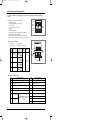
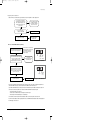
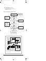
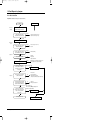
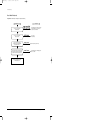
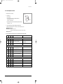
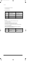
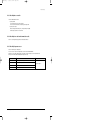
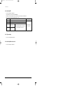
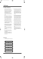
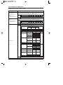
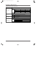
24296A(3)_2
5/29/06 9:54 AM
Page 12-1
12. Troubleshooting
12-1 Items to be checked first
1. The input voltage should be rating voltage ±10% range.
The air conditioner may not operate properly if the voltage is out of this range.
2. Is the link cable linking the indoor unit and the outdoor unit linked properly?
The indoor unit and the outdoor unit shall be linked by 4 wires.
2 wires are for power and other 2 wires are for communication, total 4 wires on each indoor unit. Check the terminals if the
indoor unit and outdoor unit are properly linked by the same number of cables and if connecting position on the terminal is
correct. Otherwise the air conditioner may not operate properly.
3. When a problem occurs due to the contents illustrated in the table below it is a symptom not related to the malfunction of the
air conditioner.
No
Operation of air conditioner
Explanation
1
In a COOL operation mode, the compressor does not
operate at a room temperature higher than the setting
temperature that the INDOOR FAN should operate.
In a HEAT operation mode, the compressor does not
operate at a room temperature lower than the setting
temperature that indoor fan should operate.
In happens after a delay of 3 minutes when the compressor
is reoperated. The same phenomenon occurs when a power
is on.
As a phenomenon that the compressor is reoperated after a
delay of 3 minutes, the indoor fan is adjusted automatically with
reference to a temperature of the air blew
2
Fan speed setting is not allowed in AUTO(
DRY(
) mode.
The speed of the indoor fan is set to LL in DRY mode.
Fan speed is 5 steps and is selected automatically in AUTO
mode.
3
Compressor stops operation intermittently in
DRY(
) mode.
Compressor operation is controlled automatically in DRY mode
depending on the room temperature and humidity.
4
Compressor of the outdoor unit is operating although
it is turned off in a HEAT mode.
When the unit is turned off while de-ice is activated, the
compressor continues operation for up to 12 minutes (maximum) until the deice is completed.
5
Timer LED(
) only of the indoor unit lights up and
the air conditioner does not operate.
Timer is being activated and the unit is in ready mode.
The unit operates normally if the timer operation is cancelled.
6
The compressor and indoor fan stop intermittently in
HEAT mode.
The compressor and indoor fan stop intermittently if room
temperature exceeds a setting temperature in order to protect
the compressor from overheated air in a HEAT mode.
7
Indoor fan and outdoor fan stop operation
intermittently in a HEAT mode.
The compressor operates in a reverse cycle to remove
exterior ice in a HEAT mode, and indoor fan and outdoor fan
do not operate intermittently for within 20% of the total heater
operation.
8
The compressor stops intermittently in a
COOL mode or DRY mode, and fan speed of the
indoor unit decreases.
The compressor stops intermittently or the fan speed of the
indoor unit decreases to prevent inside/outside air frozen
depending on the inside/outside air temperature.
Samsung Electronics
) or
12-1
24296A(3)_2
5/29/06 9:54 AM
Page 12-2
12-2 Checking and Testing operations
To complete the installation, perform the following checks and tests to ensure that the air conditioner is operating
correctly.
1.
1.
1.
1.
1.
1.
1.
1.
1.
1.
1.
Review all the following elements in the installation:
• Installation site strength
• Piping connection tightness not to leak any gas
• Connection wiring
• Heat-resistant insulation of the piping
• Drainage
• Earthing wire connection
• Setting number of the indoor unit installed (Outdoor unit SW)
• Addressing mode (AUTO or MANUAL)
• Address number on each indoor unit (Manual addressing mode)
• Correct operation for checking connection (follow the step below)
AUTO
Addressing
1
MANUAL
Addressing
2
3
4
Number of
indoor unit
7 segment
LED
2digits x 2
K1
K2
K3
K4
2. ■ Key Options of PCB Display
2. ■ - K1 : Test button
- K2 : Function button
2. ■ - K3 : Reset button
- K4 : View mode change button
SW02
Key
K1
K2
K3
K4
Switch
Push
SW01
(OFF)
DIS01
1
Heat mode
Try-run
(Display:
)
Refrigerant
Charging
(Display:
)
2
-
Cool mode
Try-run
(Display:
)
Number of
indoor unit
Indoor unit
address
K1
Reset
3
-
Pump down
(Display:
)
4
-
Checking of
pipe connection
(Display:
)
DIS02
K2
View mode
change
K3
K4
View data display
Outdoor PCB Display
2. ■ K4 View mode Display changes
Push
Push
Display Explanation
0
Present Compressor Frequency
7
Fan RPM (H: high, L: low, Blank: off)
1
Target Compressor Frequency
8
Discharge temperature
2
Order Compressor Frequency
9
OLP temperature
3
EEV0 current step
10
Condenser temperature
4
EEV1 current step
11
Outdoor temperature
12
Primary current
5
EEV2 current step
13
Target Discharge temperature
14
Total capacity of the indoor units
15
Safety control code
6
12-2
Display Explanation
EEV3 current step
MH040FXEA2/MH052FXEA2/MH14✳✳2X/
MH16✳✳2X/MH18✳✳2X/MH19✳✳2X
Always Zero
Samsung Electronics
24296A(3)_2
5/29/06 9:54 AM
Page 12-3
Troubleshooting
2. Apply the power to the outdoor unit.
Outdoor unit will try to communicate the specified number of indoor units by SW01 on outdoor display PCB.
Does LED show "Normal display"?
"Normal display" means, right 2 digit of
LED on Display PCB displays '00' and
left 2 digit of LED displays indoor unit
address number.
Yes
OK : This number is displayed
only while communicating,
so each number is displayed
for a short time in order.
Yes
Is error code started with ''
displayed on the LED?
No
''
Nothing is displayed on the LED.
Yes
Check the power source,
power cable & FUSE on
the outdoor unit.
Check the indoor unit, outdoor unit or wiring
according the error code table.
2. ■ In case of AUTO ADDRESSING mode (SW2-1:ON)
Press K2 switch 4 times to start
"PIPE CHECK MODE". After starting this
mode, LED on the left is displayed "K5"
Yes
"PIPE CHECK MODE" finished without error
: It takes 5 to 50 minutes to complete.
(This time depends on the outdoor
temperature and number of indoor unit.)
• Press K2 switch once to cancel this mode.
• During this mode LED on the right 2 digit
shows EEV number and the indoor
address which is checking at the
time.(See right figure)
K5
Yes
OK : LED shows
"Normal display" & press K3
to restart the system.
EEV Indoor
number unit
0,1,2,3 Address
LED display under PIPE CHECK MODE
Yes
If finished with error, Right digit will show
the EEV number which is the wrong PIPE
connection. In case of two or more wrong
connection, error EEV number will display
each for 1 second in order.
No
display
Yes
After Confirm the error,
press K3 to system reset.
No
Do this mode again.
Error EEV
number
0,1,2,3
LED display when PIPE CHECK ERROR
- This mode is for finding the combination between indoor unit and each valve on the outdoor unit. Because refrigerant flow is
controlled with EEV in the outdoor, controller should know which EEV will control which indoor unit.
- Once "PIPE CHECK MODE" is done normally, each indoor unit will remember the given address number by the outdoor unit
and no need to do this checking. But in case of listed below, PIPE CHECK MODE should be done again.
2. - • Re-install the system (ie.house moving)
2. - • Remove indoor unit, Add new indoor unit, Change indoor PCB for repair.
2. - • Mode change from "manual addressing" to "auto addressing"
- On this mode the controller will ignore the manual address number set on the rotary switch on the indoor PCB.
- To confirm the indoor address number assigned by this mode, use "TEST MODE" and the address number will be displayed on
the LED display on the indoor unit.
Samsung Electronics
12-3
24296A(3)_2
5/29/06 9:54 AM
Page 12-4
Troubleshooting
■ In case of MANUAL ADDRESSING mode. (SW02-1:OFF)
2. ■ Checking the address number correctly on each indoor unit PCB.
2. ■ - "PIPE CHECK MODE" is also able to use.
● If Error code is displayed on indoor or outdoor LED, check as follows;
SW01 setting number and the number of
indoor unit installed are the same.
Yes
SW01 setting number must same
as the number of indoor unit.
Yes
Check communication wire and
power wire connection.
Yes
Check PIPE connection,
because gas flow to a different
indoor unit will cease these error.
Yes
Confirm power cable connection,
especially miss-wiring between
communication cable and
power cable.
Yes
Some indoor unit has no power.
No
Error code E101 or E185 is displayed on
indoor unit LED
No
AC power line could be
connected to outdoor
communication terminal,
F1&F2. So check the wiring not
only communication line but
also power line.
Yes
Error code E460 is displayed on
outdoor unit LED.
No
Error code E401, E404 or E416 is
displayed on outdoor unit LED.
No
In case of communication error by
wrong wiring on the indoor unit,
all indoor units display an error code.
In this case, correction at the wrong point
could solve all indoor unit error display.
RAC(MH✳✳✳FPEA✳ /
MH✳✳VP2-✳✳)
indoor PCB
0
Duct(MH✳✳✳FDEA)
indoor PCB
0
1 way cassette
(MH✳✳✳FKEA)
indoor PCB
Address number switch
0
0
RAC(MH✳✳✳FWEA /
MH✳✳VW2-✳✳)
indoor sub PCB
12-4
0
0
Duct(MH✳✳✳FEEA)
indoor PCB
0
Mini 4 way cassette
(MH✳✳✳FMEA)
indoor PCB
Samsung Electronics
24296A(3)_2
5/29/06 9:54 AM
Page 12-5
12-3 Fault Diagnosis by Symptom
12-3-1 Basic Check Flow
Preparation : multimeter (AC voltage, DC voltage, Resistance)
START
Short check
for safety
Check point
Detach cable cover of the terminal blocks
(HANDLE CABI RH) on outdoor unit.
Check resistance value between
L and N of Main power terminal block.
No Good
• Outdoor unit controller (see 12-3-2)
• Indoor unit controller (see 12-3-3)
No Good
• Power cable (see 12-3-4, 12-2)
• Breaker
OK : over 180KΩ
Apply the power
Power Source
check
Check AC voltage between L and N of
MAIN power terminal block.
OK : 207-253V(50Hz)
Check AC voltage between L and N of
power terminal block for indoor unit.
Outdoor unit
No Good
Terminal block wiring
OK : 207-253V
Is there any display of LED?
No
Yes
No Good
Start operation
Any Error code on LED display?
Wait for 5 minutes to check error
code because some error judgement
needs long time.
• Main PCB,
• Display PCB,
• wiring between PCBs.
Starting by remocon or ON/OFF switch on the indoor
unit or K2 button on the Outdoor PCB display.
Yes
Error code starts in ''
''
Consult error code table
No
Indoor unit
Receiving of remote control signal ?
(Check by buzzer sound)
No
• Remote control
• Remote control battery
• Infrared signal receiving path
(front panel duct, infrared receiving module, wiring)
Yes
Check operation ON/OFF by the button
at lower right of the display module
(By buzzer sound and LED display)
Ok
Any Error code on LED display?
Wait for 5 minutes to check error code
because some error judgement
needs long time
No
• Indoor unit,
• Wiring cable to outdoor unit
Yes
Error code starts in '' ''.
Error code consists of 4 digits and displays first 2
digit and last 2 digit alternatively.
Consult error code table
Check Major parts(See 12-5)
Consult error code(Next Page)
Samsung Electronics
12-5
24296A(3)_2
5/29/06 9:54 AM
Page 12-6
Troubleshooting
Basic Check Flow(cont.)
Preparation : multimeter (AC voltage, DC voltage, Resistance)
Consult Error Code
Check point
,
,
,
,
Is the error code related to
communication ?
,
• Cable wiring between indoor and outdoor
• Communication wire socket check on
outdoor unit controller PCB
No
Is the error code related to
cycle protection ?
,
• Cycle check
• Pipe matching
No
Are some of the indoor units’
operation mode (cooling/heating)
different from others ?
,
Each indoor unit operation mode
No
Error related to outdoor controller except
temperature sensor and communication
between indoor unit and outdoor unit ?
--
Consult LED pattern on wiring diagram on
outdoor controller
No
See Error Code Table and Check
“Main checking point”
12-6
Samsung Electronics
24296A(3)_2
5/29/06 9:54 AM
Page 12-7
Troubleshooting
12-3-2 Checking Outdoor Controller
1. Making sure the wire connections.
Live side
2. Checking AC line
1) Checking FUSE
2) Checking resistance between 'L wire (BRN)' and 'DB01 Live
side' normal value : 190 - 210Ω
If value is ∞ then check R001.
3) Checking resistance between 'N wire (SKYBLU)' and 'DB01 Neutral side'
normal value : 0 - 0.1Ω
Neutral side
BD01
3. Checking ON/OFF pattern of LED1(Red), LED2(Green), LED3(Yellow)
Apply the power then ALL LEDs are on for about 1 second. then changed to as follow.
■ LED1 (Red) : ALWAYS ON
■ LED2 (Green) : Blinking 4 times a second
(This means communication between 2 micoms IC01 and IC50 is normal)
■ LED3 (Yellow) : OFF
● In case of another pattern inverter micom detects some hardware trouble or abnormal condition.
Yellow
Green
Red
Description
Note
Status indication
OFF
OFF
OFF
Power OFF / No power (SMPS error)
ON
ON
ON
Power on reset ( 1~2 seconds )
OFF
Blink
ON
Normal operation
If always in this pattern IC01(inverter micom)
has some trouble.
Hardware trouble
OFF
OFF
ON
Communication Error between
Main micom and inverter micom
Blink
Blink
ON
Current sensor error
ON
Blink
Blink
DC-LINK sensor error
ON
ON
Blink
AC-Line zero crossing error
DC LINK capacitor discharged.(Max 20sec.)
ON
OFF
Blink
Option error (EEPROM error)
After power off this error will display until
Abnormal condition
OFF
OFF
Blink
Comp. peak current (Over Current)
OFF
Blink
OFF
Comp. starting error
ON
OFF
ON
Comp. rotation error
OFF
ON
Blink
DC-Link voltage error
Blink
ON
OFF
Unit Over current protection
Samsung Electronics
12-7
24296A(3)_2
5/29/06 9:54 AM
Page 12-8
Troubleshooting
4. Checking Display PCB LED if Error code is displayed.
See error code table if displayed.
5. Checking DC voltage on each point
Item
Measuring point
Normal value
Q803 E(-)~D101 Cathode (+)
about 1.4 times as much as Power AC Voltage
ex) AC220V → 305~310Vdc
C803 voltage
14.5V~15.5V
Main control 12V
CN59 pin 1~pin 3
12V~15V
Main control 5V
CN59 pin 1~pin 2
4.75V~5.25V
DC LINK
inverter 15V
6. Checking PFC
6. When Input current is over 3.0A PFC circuit will work to control the harmonics of AC current.
Checking is measuring DC-LINK voltage.
PFC ON (Compressor is working) : DC LINK voltage is over 300Vdc (AC line >220V )
After starting compressor DC Link voltage is going down because of compressor load.
But in case of 3.0A above , DC link voltage will go up over 300V. This voltage is in proportion to AC input voltage.
Current can be monitored with "VIEW MODE".
Press K4 key on the outdoor display PCB for several times to change the display to sensor temperature value.
Left 1 digit of the LED is data index and Right 3 digits are the value
Index
C
12-8
Value
Estimated Primary current value from
Compressor current
Remark
The unit is 0.1A
Samsung Electronics
24296A(3)_2
5/29/06 9:54 AM
Page 12-9
Troubleshooting
12-3-3 Checking Indoor controller
1. MH✳✳✳FPEA✳ /MH✳✳VP2-✳✳
1.
1.
1.
1.
1.
1.
1) Checking FUSE
1) This control PCB has 2 fuses, F701 and F702.
1) If F702 is blown PCB circuit has some damage and replace PCB.
2) Checking DC voltage
■ Measure voltage between CN32 pin 1 (+12V) and CN32 pin 2 (GND).
■ Normal voltage is between 11.5V and 12.5V.
12-3-4 Checking Power cable and Communication cable
See 12-2 "Checking and Testing operations" and installation manual.
12-3-5 Checking Temperature sensor
See 12-5 "Fault Diagnosis of Major Parts".
In case of a sensor in outdoor unit, temperature can be monitored with "VIEW MODE".
Press K4 key on the outdoor display PCB for several time to change the display to sensor temperature value.
Left 1 digit of the LED is data index and Right 2 digits are the value.
Index
Value
8
Discharge sensor temperature
9
OLP sensor temperature
A
Condenser sensor temperature
B
Outdoor sensor temperature
Samsung Electronics
Remark
The unit is degree C
12-9
24296A(3)_2
5/29/06 9:54 AM
Page 12-10
Troubleshooting
12-3-6 Checking EEV
See 12-5 "Fault Diagnosis of Major Parts".
Current EEV step value can monitored with "VIEW MODE"
Press K4 key on the outdoor display PCB for several time to change the display to current EEV value.
Left 1 digit of the LED is data index and Right 3 digits is the value.
Index
Value
3
EEV-A step
4
EEV-B step
5
EEV-C step
MH040FXEA2/MH052FXEA2/MH14✳✳2X/MH16✳✳2X/
MH18✳✳2X/MH19✳✳2X Always Zero
6
Remark
The step value range is
between Zero and 480.
EEV-D step
12-3-7 Pipe matching
See 12-2 "Checking and Testing operations".
12-3-8 Checking Motor in indoor unit
See 12-5 "Fault Diagnosis of Major Parts".
12-10
Samsung Electronics
24296A(3)_2
5/29/06 9:54 AM
Page 12-11
12-4 PCB Inspection
12-4-1 Cautions for Part Replacement
1. The human body carries much static electricity.
Before touching a part for repair, replacement or the
similar purpose, be sure to touch a grounded metallic portion by hand to let the static electricity go
through the metallic portion to the earth.
Especially when handling any micro computer or IC,
carefully remove such static electricity before touching them.
2. When repairing any part on a work bench, be sure
to place an insulative sheet on the bench and always
keep the sheet surface neat without any metal fragments. If any such fragment touches a part, a secondary trouble will possibly be caused in the part.
3. Before replacing any parts, be sure to turn off the
power supply. If such replacement is done with the
power supply kept on, an electric shock, short circuit
or destruction of a part may result.
4. During replacement or repair of a part, carefully handle it : The printed circuit board has fine lead wires
(jumper wires) and glass-made parts (diode) on its
substrate.
So if a circuit board is roughly handled, such lead
wires and parts will be easily broken or damaged by
bending or shock.
5. When soldering the lead wires of any new part, be
sure to polish them using an emery paper or the like
before soldering them.
Since the lead wires of any new part are covered
with an oxide film, solder cannot adhere to the lead
wires if not polished.
6. When soldering any part, care should be exercised
not to apply any high-wattage soldering iron to the
part for a long time. Some parts are of so low a heat
resistance that they may be broken or have the
properties changed if a soldering iron is so applied
(Otherwise, the pattern may possibly be separated
and raised).
7. The heat of the soldering iron should be transferred
to the entire object to be soldered. If the solder
pieces are not well fused due to insufficient transfer
of the heat from the soldering iron, no satisfactory
electrical continuity can be assured even if the soldered objects appear well connected to each other.
8. The solder used should be limited to a minimum.
If excessive solder is used, it will cause inter-pattern
contact, which may cause malfunction of the circuit.
9. Although some part of the PCB surface are coated
with coating material for protection from dust and
dirt, soldering is also available to the coating part.
Because this coating is thin and is weak for soldering heat.
But coating material remaining on the solder part
should be cleaned up before soldering a new
component to prevent the solder part from becoming
bad conduction.
12-4-2 Procedure
12-4-2 The parts should be replaced in the following procedure.
Check for any faulty part.
Detach the faulty part.
Replace it with a new part.
Check the operation of the new part.
The repair is completed.
Samsung Electronics
12-11
12-5 Fault Diagnosis of Major Parts
Preparation : multimeter (AC voltage, DC voltage, Resistance)
Part
Indoor
Temperature sensor
Heat exchanger in/out sensor
Outdoor
Temperature sensor
Condenser temperature sensor
Diagnosis
Measure the resistance between terminals of the sensor connector housing. In case of outdoor
unit sensor, "view mode" is used for checking sensor temperature. In case of Indoor temperature
sensor, temperature is displayed on the display unit in "Fan Mode" operation.
Normal
Abnormal
Ambient temperature
Resistance of sensor[KΩ]
15˚C
14.7
20˚C
12.1
25˚C
10
30˚C
8.3
25˚C
6.9
40˚C
5.8
∞, 0Ω...open or short
Measure the resistance between terminals of the sensor connector housing.
In case of outdoor unit sensor, "view mode" is used for checking sensor temperature.
Outdoor
Discharge temperature sensor
OLP temperature sensor
Normal
Abnormal
Ambient temperature
Resistance of sensor[KΩ]
0˚C
553
10˚C
362
20˚C
242
30˚C
166
40˚C
165
50˚C
82
∞, 0Ω...open or short
Measure the resistance between terminals of the Motor connector housing
Normal
At the normal temperature (10˚C - 30˚C)
Resistance[Ω]
Terminals(wire color)
Yellow-Blue
Yellow-Red
MH035FPEA MH052FPEA
*MH✳✳✳✳✳✳✳ MH✳✳✳✳✳-12 MH052FPEA1
250~280
250~280
120~150
420~480
330~370
120~150
Remark
Main
Sub
*MH020FPEA /MH023FPEA/MH026FPEA/MH✳✳✳✳✳-07/MH✳✳✳✳✳-09
Terminal(wire color)
Yellow-Blue
Blue-Red
Indoor Fan Motor
Yellow-Red
Yellow-Blue
Red-Yellow
Yellow-Red
Model
Bender
Resistance(Ω) Remark
SHIBAURA
356~435
MH023/026/035FWEA
SINYA
531~650
MH✳✳VW2-✳✳
DAEYANG
312~381
SUNGSHIN
130~159
MH052FWEA
DAEYANG
211.5~258.5
MH026FKEA
SHIBAURA
314.7~425.7
MH035FKEA
NEW MOTECH 142.8~193.2
MH030FMEA
Main
NEW MOTECH 115.6~156.4
MH035FMEA
MH052FMEA
MH023FEEA
MH026FEEA
MH035FEEA
MH052FEEA
MH052FDEA
SINYA
OYANG
SHIBAURA
MH023/026/035FWEA
SINYA
MH✳✳VW2-✳✳
DAEYANG
SUNGSHIN
MH052FWEA
DAEYANG
MH026FKEA
SHIBAURA
MH035FKEA
NEW MOTECH
*White-Blue
MH030FMEA
MH035FMEA
MH052FMEA
*White-Yellow
MH023FEEA
MH026FEEA
MH035FEEA
MH052FEEA
MH052FDEA
Yellow-Red
SINYA
141.4~190.9
40.1~54.3
46.8~57.2
324.9~397
320~391
252~308
106.2~130
164.7~201.3
214.4~290.2
160.7~217.3
Sub
NEW MOTECH
110.5~149.5
SINYA
122.4~165.6
SINYA
OYANG
50.3~68.1
81.9~100.1
*White wire is not short with Red wire.
Abnormal
12-12
∞, 0Ω...open or short
Samsung Electronics
24296A(3)_2
6/12/06 6:28 PM
Page 12-13
Fault Diagnosis of Major Parts(cont.)
Preparation : multimeter (AC voltage, DC voltage, Resistance)
Part
Diagnosis
Measure the resistance between terminals of the Motor connector housing
Normal
Outdoor Fan Motor
Terminals(wire color)
Resistance[Ω]
95~105
Main 1
Yellow-Blue
95~105
Main 2
Blue-White(run capa line)
60~75
Sub
0~1
Thermal fuse
Red-White Blue(run capa line)
Abnormal
Remark
Red-Blue
∞, 0Ω...open or short
Measure the resistance between terminals of the Motor connector housing
Outdoor unit EEV
Stepping motor
Normal
40-50Ω Orange-Gray, Red-Gray, Yellow-Gray, Black-Gray
Abnormal
∞, 0Ω...open or short
Measure the resistance between terminals
Crank case heater
Normal
1.1-1.3KΩ
Abnormal
∞, 0Ω...open or short
Measure the resistance between terminals of the Motor connector housing
Indoor unit step motor
Flap, Front panel
Normal
Abnormal
Samsung Electronics
Motor
Flap
Front panel
Resistance[Ω]
280~320
110~130
Terminals(wire color)
Red-Yellow, Red-Orange,
Red-Blue, Red-Pink
∞, 0Ω...open or short
12-13