1
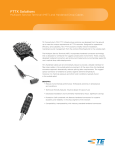
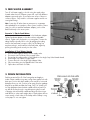
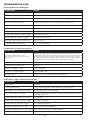
Clear Flo and Clear Flo Plus
®
Reverse Osmosis Systems
Installation & Owner’s Manual
®
Operating Parameters:
Water supply:
Feed water temperature:
Safe operating pressure:
Recommended Turbidity:
Recommended pH Range:
Recommended Max. Hardness:
Total Dissolved Solids (TDS):
Tank Air Pressure:
Potable water
40º F — 85º F
40-80 PSI
<5 NTU
5-8
7 GPG (120 PPM)
2000 PPM
8-11 PSI (empty)
Warning:
• Open the spigot to flush water from first tank.
•U
nit must be connected to a municipal or well water source that
is tested on a regular basis to insure bacteriologically safe water.
• After installation check the unit for leaks.
•D
o not allow unit to freeze. The membrane contains water and
will be destroyed if frozen.
• Change filters regularly.
• Do not plumb unit to hot water. Membrane will be damaged.
• Heed source water operating parameters.
• Do not use with water of unknown quality.
Common System Stages (stages and filters will vary by model and series)
Stage 1 (SDC-25-1005)
Sediment filter 5 micron
Stage 2 (UDF-10KDF.5)
KDF/Carbon filter
Stage 3 (CB-25-1005)
Carbon block
Stage 4 (TW-1812-100D)
100 gallon/day membrane
Stage 5 (AICRO-B)
In-line carbon polishing filter
Change:
Change:
Change:
Change:
Change:
6
6
6
3
6
months – 1 year
months – 1 year
months – 1 year
years – 5 years
months – 1 year
Introduction
Our reverse osmosis drinking water systems have been designed for quick and simple installation and maintenance.
By carefully reading this instruction manual and following the operational guidelines you will insure a successful
installation and reliable operation. Routine maintenance is essential to the longevity and performance of the system.
Filters should be changed regularly, depending on the quality of the feed water supply and quantity of water used.
Liability
The installer is responsible for any leaks resulting from installation of tubing or related fittings. The installer must
check over the entire unit completely while under pressure to ensure unit is not leaking and functioning properly.
Liability resulting from failure to check for leaks while under pressure is the sole responsibility of the installer.
Maximum pressure rating is 80 PSI. If local water pressure exceeds 75 PSI, a pressure regulator must be installed,
reducing the water pressure into the system.
Starting Your Installation
Component Checklist:
1 – Storage Tank
1 – RO System
1 – Faucet, supplied by dealer (with faucet install kit)
1 – Installation Kit
Avoid installation locations where the system might come in contact
with hot water pipes or other hazards. Determine the location for the
faucet. Check to see that drilling the faucet hole will not damage pipes
or wires underneath the sink. Determine the location for the storage tank. A maximum distance of 15 feet from tank
to faucet is possible. A shorter tubing run from tank to faucet will produce a faster flow out of the faucet.
Tubing and Fittings
To insure an optimal seal, tubing should be cut with the end square. An angled cut or distortion or kink of the
tubing will not provide an efficient seal and may cause leaks.
Your system may come with quick-connect or standard compression fittings. With quick-connect style fittings, simply
push the tube into the collet ring until you feel the tubing click into place. To remove, hold the collet ring flush
against the fitting while pulling the tube out in the opposite direction. Standard compression fittings will usually
have a nut, ferrule and insert. First slide the nut over the tubing end followed by the ferrule, then slide the insert
inside the tubing end. Push the tubing into the fitting as far as possible then tighten down the nut on the threads.
2
Note: It is recommended that the system’s expendable filters and membrane be thoroughly rinsed at the
shop prior to installation, and if practical the holding tank should be filled with treated water. If this rinsing
procedure is performed at the installation site, the consumer should take note that it is recommended that
the first tank of water not be consumed. Additionally, carbon filters may leach carbon dust fines on startup.
This may discolor the water initially, but should clear up quickly.
1. FAUCET INSTALLATION — supplied by dealer
Drilling the Faucet Hole
The product water faucet may be installed on any flat surface at least 2” in diameter. Check the underside
of the location for interference. Drill a hole, at least 7/16” (11mm) in diameter, through the countertop
where the faucet will be mounted (most faucets will mount to a hole diameter of up to 1-1/4”). Drilling a
1/4” (6mm) pilot hole first may be helpful. Take caution when drilling the faucet-mounting hole. Different
countertops may require special drill bits and/or installation methods.
Note: Faucet may differ from illustration.
Air Gap Faucets
1. Attach 1/4” black
waste line from R.O.
to smaller 1/4” barb
fitting under faucet.
2. Attach the 3/8”
waste line from
drain saddle to the
larger 3/8” barb.
Note: Some states require the use of an air gap faucet.
Check your local plumbing code to assure compliance.
Mounting the Faucet
Insert the faucet shank down through the drilled hole. Be sure the faucet body, faucet base, and the rubber
faucet base washer are in place above the sink as shown in Diagram A. Install the star lock-washer and nut,
and then tighten firmly while faucet is aligned in the desired location. Do not over tighten. Tip: This step may
be easier with two people. One person holds the faucet in place from above, while the other tightens the
faucet from underneath.
Note: To connect an additional point of use outlet (icemaker, extra faucet, etc.) place a tee-fitting connector
along the line between the faucet and the RO system. A line can then be run from the tee to the outlet device.
Additional fittings and/or connectors may be required. Icemakers may have proprietary connections and/or
specific pressure requirements. Check with your manufacturer for details.
3
2. FEED WATER ASSEMBLY
Turn off cold water supply to the sink using the supply valve
located under the sink. Different systems will come with different
adapters types and styles. Shown below are a few of the most
common options. Only install to cold water supplies and do not
over tighten fittings.
Note: Some shut off valves have an extra port or a separate
valve plumbed for an icemaker or filter system. In either of these
cases you will not need the feedwater adapter, just hook the
feed line directly to this access point.
Scenario 1: Plastic Feed Water
Make sure the black washer is seated in the feedwater adapter.
Tighten feedwater adapter to the valve with an adjustable
wrench. Tighten until snug but do not over tighten. Connect the
tubing feed line (usually red in color) by plugging the tubing
end into the feed water connector collet, cut the tubing line
anywhere along it, and install the inline ball valve, again by
pushing the tubing ends securely into the collets.
Installation of Feed Water Supply
1. Shut off water supply at brass/chrome supply valve.
2. Disconnect riser from brass/chrom supply valve.
3.Ensure that the sealing gasket is fully seated into the Angle Stop Valve female thread.
4. Install Angle Stop Valve on supply valve.
5. Connect the riser to the Angle Stop Adapter Valve.
6. Fully insert tubing into the Sppedfit side of the valve.
7. Open valves and check for leaks.
3. DRAIN INSTALLATION
Peel the protective film off of the foam gasket and apply to
inside of drain saddle, using care to align foam gasket hole with
drain port. Position the drain saddle on the vertical or horizontal
drainpipe from your sink. Position as far away from the garbage
disposal as possible and after the P-trap. Drill 1/4” (6mm) hole
into the drainpipe where the drain saddle will be mounted. Do
not drill all the way through—stop after piercing the first wall
of the pipe. Mount the drain saddle and align the hole using a
small drill bit or other small straight object. Gently tighten the two
screws evenly on both sides of the clamp until the clamp is snug
on the pipe. Do not over tighten.
4
4. STORAGE TANK INSTALLATION
The storage tank may be placed in either the vertical or horizontal position without affecting system performance. Put
four to five wraps of Teflon tape around the metal stem at the top of the tank. Hand tighten the plastic shut off ball
valve found in the installation packet down on to the tank stem. Do not over tighten.
Note: Tank air pressure can be measured at the air stem on the opposite side of tank. It may be covered with a blue
cap. Tank air pressure should be between 8-11 PSI when empty.
5. TUBING CONNECTIONS (systems may not have color-coded tubing or different color codes)
Feed (Red) – connects main water supply feed to elbow fitting on right side of unit
Drain (Black) – c onnects drain saddle to bottom fitting on membrane housing
(inline flow restrictor necessary on this line)
Tank (White) – connects tank ball valve to tee fitting on inline filter
Faucet (Blue) – connects faucet to elbow fitting on left side of inline filter
6. UNIT STARTUP
The RO unit may be mounted on the wall though not necessary. To mount, use the bracket holes on the RO unit
as a guide, and with the screws provided in the install pack, mount the system in the desired location. With all
tubing connections complete, turn on the cold water supply to the RO unit and open all ball valves. Ball valves are
open when the handle runs parallel to the tubing. Immediately check the entire system for leaks. If you notice any
leaks turn off water supply and tighten where necessary. With the RO system on, lift the drinking faucet handle
until water begins to drip out. Next, close the faucet to allow the tank to fill. This may take 3-4 hours depending
on size of system. Once the tank is full it is recommended to flush completely. Open and leave open the drinking
water faucet until the water coming out again slows to a dribble. This signifies the tank is empty. The drinking
faucet can then be closed to allow the tank to fill again. At this point the water is ready for consumption.
5
Clear Flo®
CFRO
14
13
21
12
26
18
11
24
17
15
10
22
20
9
25
19
8
16
4
7
3
6
2
5
23
1
27
Wrench
Part No. FWW25UNA
Part Number
Description
Qty.
Part Number
Description
1
SDC-25-1005
10” 5 micron sediment filter
1
2
FH4200W
White filter housing, 1/4” ports
3
PR-ME0404
Quick connect 1/4” elbow
4
PE-08-BI-0500F-R
1/4” red tubing
5
CB-25-1005
6
15
PR-CV1364
Quick connect 3/8” tank ball valve
1
3
16
Aqua-4
4 gallon R.O. tank
1
2
17
SC500B-14
Drain clamp
1
7 ft
18
SV-6
Self-piercing feed valve
1
10” carbon block
2
19
PR-CV0201W
Automatic shut off valve
1
PR-HN0404
1/4” hex nipple
2
20
FR-***
Flow restrictor
1
7
FM-60
Triple bracket
1
21
PR-MRT0604
Quick connect 1/4” x 3/8” x
3/8” male run T
1
8
C-2500W
Single clip membrane housing
2
22
TW-1812-100D
100 GPD TFC membrane
1
9
PR-CV3142
1
23
PE-12-BI-0500F-Y
3/8” yellow tubing
5 ft
10
DC-2500W
Quick connect 1/4” tube x
1/8” thread with check valve
Double clip membrane housing
to inline
2
24
PE-12-BI-0500F-B
3/8” blue tubing
6 ft
11
MH18
Membrane housing, 1/8” ports
1
25
PE-08-BI-0500F-E
1/4” black tubing
6 ft
12
AICRO-B
10” in-line carbon post filter
1
26
PR-FA06-716
Quick connect 3/8” faucet adapter
1
13
PR-MC0604
Quick connect 3/8” tube x
1/4” thread male connector
1
27
UDF-10KDF.5
10” KDF/carbon filter
1
14
WDF103B
Long reach chrome faucet
1
6
Qty.
Clear Flo® Plus
CFRO-PLUS
14
13
21
12
26
18
22
20
11
24
17
15
10
9
25
19
8
16
4
7
3
6
29
2
5
23
27
28
1
31
30
Part Number
Description
Qty.
Part Number
Description
Qty.
1
SDC-25-1005
10” 5 micron sediment filter
1
17
SC500B-14
Drain clamp
1
2
FH4200W
White filter housing, 1/4” ports
3
18
SV-6
Self-piercing feed valve
1
3
PR-ME0404
Quick connect 1/4” elbow
2
19
PR-CV0201W
Automatic shut off valve
1
4
PE-08-BI-0500F-R
1/4” red tubing
7 ft
20
FR-***
Flow restrictor
1
1
1
5
CB-25-1005
10” carbon block
2
21
PR-MRT0604-B
Quick connect 1/4” x 1/4” x 3/8”
male run T
6
PR-HN0404
1/4” hex nipple
2
22
TW-1812-100D
100 GPD TFC membrane
7
FM-60
Triple bracket
1
23
PE-12-BI-0500F-Y
3/8” yellow tubing
5 ft
8
C-2500W
Single clip membrane housing
2
24
PE-12-BI-0500F-B
3/8” blue tubing
6 ft
9
PR-CV3142
1
25
PE-08-BI-0500F-E
1/4” black tubing
6 ft
10
DC-2500W
Quick connect 1/4” tube x
1/8” thread with check valve
Double clip membrane housing
to inline
2
26
PR-FA06-716
Quick connect 3/8” faucet adapter
1
11
MH18
Membrane housing, 1/8” ports
1
27
UDF-10KDF.5
10” KDF/carbon filter
1
12
AICRO-B
10” in-line carbon post filter
1
Low-flow booster pump kit
1
13
PR-MC0604
Quick connect 3/8” tube x
1/4” thread male connector
1
29
(part of booster kit)
3/8” tank pressure shut-off switch
1
14
WDF103B
Long reach chrome faucet
1
30
(part of booster kit)
Y-splitter cable
1
15
PR-CV1364
Quick connect 3/8” tank ball valve
1
31
(part of booster kit)
Low-flow transformer
1
16
Aqua-4
4 gallon R.O. tank
1
28-31 PM-EC-203-100A
7
TROUBLESHOOTING GUIDE
Not Enough Water From Holding Tank
Possible Cause
Solution
Feed water valve is plugged or closed.
Open valve or unclog.
Sediment/Carbon filter(s) clogged.
Replace filters.
Low incoming water pressure.
Incoming water pressure must be above 40 PSI. Install booster or permeate pump.
Reverse osmosis membrane is fouled.
Make sure incoming water pressure is within operating limits. Make sure drain line is not
clogged. (See High TDS) Correct cause of fouling and replace R.O. membrane.
Air pressure in holding tank is incorrect.
Empty water from holding tank. Air pressure in valve stem should be between 6-8 PSI.
Air bladder in holding tank is ruptured.
Replace holding tank.
Holding tank valve is closed.
Open valve.
No water to drain. Drain flow restrictor is clogged.
Replace drain flow restrictor.
No water to drain. Air cap faucet is clogged.
Clear or replace air gap faucet.
Check valve on R.O. membrane housing is stuck.
Replace check valve.
Automatic shut-off valve malfunctioning.
Replace automatic shut-off valve.
Low Water Pressure From Dispensing Faucet
Possible Cause
Solution
Air pressure in holding tank is incorrect.
(This is the #1 reason for low flow from reverse
osmosis faucet.)
Open faucet and empty water from holding tank. Shut off feed water to system and remove
holding tank from under sink. Locate the air valve stem (just like on a car or bicycle tire) and
add air. If there is still water in the tank, continue to add air until all the water is removed.
Once all the water is removed, continue to add air and pressurize to 6-8 PSI. Re-install the
tank under the sink, turn on feed supply to the system and allow the tank to fill.
Carbon post filter is clogged.
Replace post filter.
Holding tank valve is partially closed.
Open valve.
Faucet is out of adjustment or faulty.
Repair or replace faucet.
Heavy water use. Holding tank empty.
Allow holding tank to refill.
Low water production.
See previous section on “Not Enough Water From Holding Tank.”
Product Water is High in Total Dissolved Solids (TDS)
Possible Cause
Solution
Clogged prefilter.
Replace filter.
Low incoming water pressure.
Incoming water pressure must be > 40 PSI. Install booster or permeate pump.
R.O. membrane is not correctly sealed in Housing.
Check that R.O. membrane is correctly installed.
Reverse osmosis membrane is expended.
If membrane life is unusually short, find and correct the problem. (Average life is 2-3 years.)
Replace R.O. membrane.
Product water and drain water lines are reversed.
Correct plumbing.
No water to drain. Drain Flow Restrictor is clogged.
Replace Drain Flow Restrictor.
No water to drain. Air Gap Faucet is clogged.
Clear or replace Air Gap Faucet.
The Automatic Shut-Off Valve is not closing.
Repair or replace Automatic Shut-Off Valve.
New Carbon Postfilter has not been rinsed completely. Drain Holding Tank twice to rinse new Carbon Postfilter.
The incoming feed water TDS has increased.
An increase in feed water TDS will also give an increase in Product Water TDS.
8
Tastes and Odors in Product Water
Possible Cause
Solution
Carbon post filter is exhausted.
Replace filter.
There is foreign matter in holding tank.
Clean, flush and sanitize the holding tank. Replace filters.
Product water and drain water lines are reversed.
Correct plumbing.
Dissolved gases in feed water.
Pre-treat feed water to remove gasses.
Increase in product water TDS.
See high TDS in product water section.
Drain Water Overflows at the Air Gap Faucet
Possible Cause
Solution
Air gap is clogged.
Clear air gap.
Drain line is clogged.
Clear tubing.
Drain flow rate is too high.
Replace flow restrictor.
Faucet Leaks or Drips
Possible Cause
Solution
Water leaks from faucet spout.
Adjust faucet by turning the tee bar located under the handle to provide a small amount of
free play in the handle when shut off. Should this not work, repair or replace the faucet.
Leaks from beneath the handle.
Repair or replace the faucet.
9
Important Information
Serial Number
Installation Date
Model Number
Service Record (Last Service Date)
Usage Guidelines
•D
o not use with water that is microbiologically unsafe or of unknown quality without adequate
disinfection before or after the equipment.
•W
ater supplies that exceed limits for hardness, iron, manganese and hydrogen sulfide
require pretreatment.
• Do not allow exposure to temperatures below 33°F (1°C).
• Maximum operating temperature: 85°F (38°C).
• Operating pressure: 40-80 pounds per square inch (PSI).
• This system must be installed according to local plumbing codes.
• F or optimal performance, this system requires the regular replacement of all filters to operate
properly. This system’s carbon and particulate filters should be changed at least annually and the
reverse osmosis membrane should be replaced every 3-5 years*. Fluctuation in chlorine, sediment
and TDS levels may affect the frequency of replacement.
*Chlorine may damage the reverse osmosis membrane used in this system. Your drinking water system includes
granular activated carbon which protects the reverse osmosis membrane by reducing or eliminating the presence of
chlorine. Influent chlorine should not exceed 3 mg/L. It is recommended that a water softener is used for water over
7 grains per gallon (GPD).
10
Reverse Osmosis Drinking Water System
Five/One Year Limited Warranty
Congratulations. You have purchased one of the finest water treatment systems available. In the unlikely event
of a problem due to defects in material and workmanship, we proudly warrant our reverse osmosis drinking water
system to the original owner, at original installation location, when installed within recommended parameters from
the date of original installation as follows:
For a period of FIVE YEARS:The entire reverse osmosis drinking water system with the
exception of the reverse osmosis membrane and disposable
sediment and carbon filters.
For a period of ONE YEAR:
The reverse osmosis membrane.
Any part found defective within the terms of this warranty will be repaired or replaced by the dealer at the
manufacturer’s discretion. You pay only freight from our factory and local dealer charges. To obtain local warranty
service, contact original dealer. If original dealer is unknown, contact Water-Right for authorized service dealer in
your area. If no authorized dealer is located in your area, please ship defective part or component freight prepaid to:
Water-Right, Inc.
1900 Prospect Ct.
Appleton, Wisconsin 54914
Water-Right, at its discretion, will repair or replace the part or component at its expense and return part freight collect.
The above provisions of the warranty are valid as long as the system is connected in compliance with local plumbing
codes and in an equivalent manner and condition of the original installation and is owned by the original owner.
This warranty does not cover damages due to accident, fire, flood, freezing, or any other Act of God. Water-Right
is not responsible for damages due to change in water conditions, misapplication, misuse, neglect, vacuum,
oxidizing agents, alteration, or lack of maintenance. No responsibility is assumed for loss of use of the system,
inconvenience, loss or damage to real or personal property or any incidental or consequential damages.
Furthermore, we assume no liability and extend no warranties, express or implied, for the use of this product with
a non-potable water source. To the extent permitted by law, Water-Right disclaims all implied warranties,
including without limitation warranties of merchantability and fitness for particular purpose; to the extent
required by law, any such implied warranties are limited in duration to the period specified above for the
specified components.
Some states do not allow limitations on how long an implied warranty lasts, so the above limitation may not apply
to you. Some states do not allow the exclusion or limitation of incidental or consequential damages, so the above
limitation or exclusion may not apply to you. This warranty gives you specific legal rights, and you may also have
other rights which vary from state to state.
11
Manufactured at:
1900 Prospect Court • Appleton, WI 54914
Phone: 920-739-9401 • Fax: 920-739-9406
© 2014 Clear Flo All rights reserved.
LIT-CLR FLO MAN ENVINK 1/14 1M


![研修テキスト[PDF:3.2MB]](http://vs1.manualzilla.com/store/data/006663526_3-d562ed6b3f7d41d86a4472e13151558e-150x150.png)