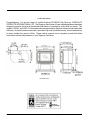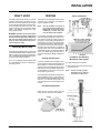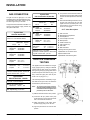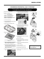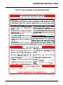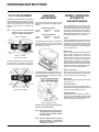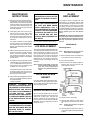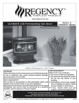
1
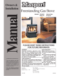
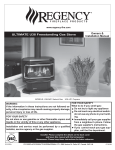
www.regency-fire.com
ULTIMATE U38 Freestanding Gas Stove
MODELS: U38-NG Natural Gas
Owners &
Installation Manual
U38-LP Propane
FOR YOUR SAFETY
WARNING:
If the information in these instructions are not followed exactly, What to do if you smell gas:
Do not try to light any appliance
a fire or explosion may result causing property damage,
Do not touch any electrical switch:
personal injury or loss of life.
do not use any phone in your
FOR YOUR SAFETY
building.
Do not store or use gasoline or other flammable vapors and
Immediately call your gas supplier
liquids in the vicinity of this or any other appliance.
from a neighbour's phone. Follow
the gas supplier's instructions.
Installation and service must be performed by a qualified
If you cannot reach your gas
installer, service agency or the gas supplier.
supplier, call the fire department.
Tested by:
Installer: Please complete the details on the back cover
and leave this manual with the homeowner.
Homeowner: Please keep these instructions for future reference.
918-026a
FPI FIREPLACE PRODUCTS INTERNATIONAL LTD. 6988 Venture St., Delta, BC Canada, V4G 1H4
01/09/06
To the New Owner:
Congratulations! You are the owner of a state-of-the-art ULTIMATE Gas Stove by FIREPLACE
PRODUCTS INTERNATIONAL LTD. The Regency Gas Series of hand crafted appliances has been
designed to provide you with all the warmth and charm of a woodstove, at the flick of a switch. The
models U38-NG, and U38-LP of this series has been approved by Warnock Hersey for both safety and
efficiency. As it also bears our own mark, it promises to provide you with economy, comfort and security
for many trouble free years to follow. Please take a moment now to acquaint yourself with these
instructions and the many features of your Regency Gas Stove.
U38-NG & U38-LP
2
Regency U38 ULTIMATE Freestanding Gas Stove
TABLE OF CONTENTS
Page
Page
Safety Label
Operating Instructions
Specifications ........................................................... 2
Operating Instructions ............................................. 14
Safety Label ............................................................. 4
Lighting Instructions ................................................ 14
Shutdown Instructions ............................................. 14
Installation
General Installation Information ................................... 5
Installation Checklist ................................................. 5
Minimum Clearances to Combustibles ........................ 6
Optional Outside Air .................................................. 6
- Outside Air through Bottom of Pedestal .................. 6
- Outside Air through Rear of Pedestal ...................... 7
Draft Hood ................................................................ 7
First Fire ................................................................ 14
Convection Fan Operation ........................................ 14
Flame Height Adjustment ........................................ 14
Copy of Lighting Plate Instructions ............................ 15
Pilot Adjustment ..................................................... 16
Aeration Adjustment ................................................ 16
Normal Operating Sounds of Gas Appliances ............ 16
Maintenance
High Elevation ........................................................... 7
Venting .................................................................... 7
Maintenance Instructions ......................................... 17
- Venting Requirements ........................................... 7
Log Replacement .................................................... 17
- Flue Mounting Bracket .......................................... 7
Gold Plated Doors ................................................... 17
- Vent Terminations ................................................. 7
Door and Glass Gasket ........................................... 17
- Installation into Existing Woodstove Flue System. ... 7
Glass Replacement ................................................. 17
Gas Connection ........................................................ 8
- Mitred Door ........................................................ 17
System Data ............................................................ 8
- Panel Door ......................................................... 18
Gas Pressure Test .................................................... 8
Fan Maintenance .................................................... 18
Conversion from Natural Gas to Propane ..................... 9
- Replacing Fan .................................................... 18
Conversion to Lower Btu .......................................... 10
Removing Valve ...................................................... 19
Log Installation ....................................................... 10
Parts List ............................................................... 20
Door Installation and Door Latch ............................... 12
U38 Louver Installation ............................................. 12
Warranty
Test for Flue Spillage ............................................... 12
Optional Wall Thermostat ........................................ 12
Warranty ................................................................ 23
Optional Remote Control Installation ......................... 13
Final Check ............................................................ 13
Wiring Diagram ....................................................... 13
Regency U38 ULTIMATE Freestanding Gas Heater
3
SAFETY LABEL
This is a copy of the label that accompanies
each ULTIMATE Freestanding Gas Stove. We
have printed a copy of the contents here for
your review. The safety label is located on the
inside of the drop down pedestal door.
NOTE: Regency units are constantly being
improved. Check the label on the unit and if there
is a difference, the label on the unit is the correct
one.
Copy of the Safety Label for the U38 Freestanding Gas Stove
For the State of Massachusetts, installation and repair must be done by a plumber or gasfitter licensed in the Commonwealth of Massachusetts.
For the State of Massachusetts, flexible connectors shall not exceed 36 inches in length.
For the State of Massachusetts, the appliances individual manual shut-off must be a t-handle type valve.
4
Regency U38 ULTIMATE Freestanding Gas Stove
INSTALLATION
IMPORTANT:
SAVE THESE
INSTRUCTIONS
BEFORE YOU START
Safe installation and operation of this appliance
requires common sense, however, we are
required by the Canadian Safety Standards
and ANSI Standards to make you aware of the
following:
INSTALLATION AND REPAIR
SHOULD BE DONE BY A QUALIFIED SERVICE PERSON. THE APPLIANCE SHOULD BE INSPECTED BEFORE USE AND AT LEAST
ANNUALLY BY A PROFESSIONAL
SERVICE PERSON. MORE FREQUENT CLEANING MAY BE REQUIRED DUE TO EXCESSIVE LINT
FROM CARPETING, BEDDING
MATERIAL, ETC. IT IS IMPERATIVE THAT CONTROL COMPARTMENTS, BURNERS AND CIRCULATING AIR PASSAGEWAYS OF
THE APPLIANCE BE KEPT CLEAN.
DUE TO HIGH TEMPERATURES,
THE APPLIANCE SHOULD BE LOCATED OUT OF TRAFFIC AND
AWAY FROM FURNITURE AND
DRAPERIES.
WARNING: FAILURE TO INSTALL
THIS APPLIANCE CORRECTLY
MAY CAUSE A SERIOUS HOUSE
FIRE AND WILL VOID YOUR WARRANTY.
CHILDREN AND ADULTS SHOULD
BE ALERTED TO THE HAZARDS
OF HIGH SURFACE TEMPERATURES, ESPECIALLY THE FIREPLACE GLASS, AND SHOULD
STAY AWAY TO AVOID BURNS
OR CLOTHING IGNITION.
YOUNG CHILDREN SHOULD BE
CAREFULLY SUPERVISED WHEN
THEY ARE IN THE SAME ROOM AS
THE APPLIANCE.
CLOTHING OR OTHER FLAMMABLE MATERIAL SHOULD NOT BE
PLACED ON OR NEAR THE APPLIANCE.
The ULTIMATE Freestanding Gas Stove must
be installed in accordance with these instructions. Carefully read all the instructions in this
manual first. Consult the "authority having jurisdiction" to determine the need for a permit prior
to starting the installation.
12) Under no circumstances should this appliance be modified. Parts that have to be
removed for servicing should be replaced
prior to operating this appliance.
13) Installation and any repairs to this appliance
should be done by a qualified service person. A professional service person should
be called to inspect this appliance annually.
Make it a practice to have all of your gas
appliances checked annually.
14) Do not strike the glass door.
GENERAL SAFETY
INFORMATION
15) Under no circumstances should any solid
fuels (wood, paper, cardboard, coal, etc.)
be used in this appliance.
1) The appliance installation must conform
with local codes or, in the absence of local
codes, with the current Canadian or National Gas Codes, CAN1-B149 or ANSI-223.1
Installation Codes.
16) The appliance area must be kept clear and
free of combustible materials, (gases and
other flammable vapours and liquids).
2) The appliance when installed, must be electrically grounded in accordance with local
codes, or in the absence of local codes with
the current National Electrical Code, ANSI/
NFPA 70 or CSA C22.1 Canadian Electrical
Code.
3) This appliance is Listed for bedroom installations when used with a Listed Millivolt
Thermostat. Some areas may have further
requirements, check local codes before
installation.
4) This appliance is Listed for Alcove installations, maintain minimum Alcove clearances
as follows, minimum ceiling height of 66",
minimum width of 48" and a maximum depth
of 36".
5) This unit is not approved for installation into
a mobile home.
6) See general construction and assembly
instructions.
7) This appliance must be connected to a vent
and terminate to the outside of the building
envelope. Never vent to another room or
inside a building.
17) Do not connect this gas appliance to chimney flue serving a separate sold-fuel burning appliance.
18) WARNING: Operation of this appliance when
not connected to a properly installed and
maintained venting system or tampering
with the blocked vent shutoff system can
result in carbon monoxide (CO) poisoning
and possible death.
19) This appliance needs fresh air for safe
operation and must be installed so there are
provisions for adequate combustion and
ventilation air.
Emissions from burning wood or gas could
contain chemicals known to the State of
California to cause cancer, birth defects or
other reproductive harm.
INSTALLATION
CHECKLIST
1) Check Clearances to Combustibles, page 6.
2) If you are using outside air, page 6.
3) Install venting, page 7.
8) Inspect the venting system annually for
blockage and any signs of deterioration.
9) Any safety glass removed for servicing
must be replaced prior to operating the
appliance.
10) To prevent injury, do not allow anyone who
is unfamiliar with the operation to use the
fireplace.
4) Make gas connections, page 8. Test the
pilot. Must be as per diagram, page 16.
5) If necessary, convert Natural Gas to Propane (page 9), or convert to lower Btu
(page 10).
6) Test Gas Pressure, page 8.
7) Install log set where indicated on page 10.
11) Wear gloves and safety glasses for protection while doing required maintenance.
Regency U38 ULTIMATE Freestanding Gas Heater
8) Install Front Door, page 12.
5
INSTALLATION
9) Install Louvers, page 12.
OPTIONAL
OUTSIDE AIR
U38-NG & U38-LP Clearances
10) Test for flue spillage (draft test), page 12.
11) Install optional Remote Control, or Wall Thermostat, pages 12 and 13.
12) Final check, page 13.
A Side Wall to Unit
7-1/2" / 190 mm
B Back Wall to Unit
6" / 155 mm
E Side Wall to Unit
2" / 50 mm
Outside air for combustion can be brought in
either through the bottom of the pedestal or
through the rear plate of the pedestal.
U38-NG & U38-LP REFERENCE
Before leaving this unit with the customer, the
installer must ensure that the appliance is firing
DIMENSIONS
correctly and operation fully explained to cusC
Back
Wall
to
Flue
Centerline 10-3/4" / 273 mm
tomer.
D Side Wall to Flue Centerline 20-1/2" / 520 mm
This includes:
F Side Wall to Flue Centerline 11" / 280 mm
1) Clocking the appliance to ensure the correct firing rate (rate noted on label) after
burning appliance for 15 minutes.
For both bottom and rear "outside air" the
Pedestal Cover Plate must be installed. Loosen
the 4 screws on the rear of the pedestal and
slide the cover plate over them. Slide the plate
to the left to center it and tighten down the 4
screws.
Outside Air Through
Pedestal Bottom
Once you have properly marked the position of
your unit as outlined in "General Information"
and "Clearances to Combustibles", cut a properly sized hole though the floor directly under
your pedestal base to the outside. Pipe fresh
air into the pedestal area by using appropriate
metallic duct pipe with a mesh grill at the outside
termination. Do not remove the knockout.
2) If required, adjusting the primary air to
ensure that the flame does not carbon. First
allow the unit to burn for 15-20 min. to
stabilize.
CAUTION: Any alteration to the product that
causes sooting or carboning or that results in
damage is not the responsibility of the manufacturer.
CLEARANCES TO
COMBUSTIBLES
The clearances listed below are MINIMUM distances. Measure the clearance to both the
appliance and the chimney connector. (The
farthest distance is correct if the two
clearances do not coincide.) For example, if
the appliance is set as indicated in one of the
figures but the connector is too close, move the
stove until the correct clearance to the connector is obtained.
Rear View
Minimum ceiling height is 36" / 914 mm
from top of unit.
Outside Air Through
Rear of Pedestal
Remove the blanking plate from the rear of the
pedestal cover plate and bend the two tabs out
90 degrees. Pipe fresh air into the pedestal area
by using duct pipe with a mesh grill at the outside
termination. Attach the pipe to the tabs with
screws.
This unit can be installed on a solid combustible
surface like a wood floor. This unit can also be
installed directly on carpeting or vinyl when the
bottom pedestal cover plate (provided with unit)
is installed.
This appliance may be installed only with the
clearances as shown in the situations pictured.
Do not combine clearances from one type of
installation with another in order to achieve
closer clearances.
Use the minimum clearances shown in the
diagrams below for installation with "B" vent.
Side View
If further reduced clearances are needed, obtain requirements for construction of a protected wall from your local building authorities and
their allowable reductions of the listed clearances.
6
Regency U38 ULTIMATE Freestanding Gas Stove
INSTALLATION
DRAFT HOOD
VENTING
This heater has a draft hood built in. It must not
be altered, obstructed, or blocked in any way,
and the unit must be installed so that the draft
hood is in the same atmospheric pressure zone
as the combustion air inlet to the burner. This
heater must be properly connected to a venting
system. This heater is equipped with a vent
safety shutoff system.
This heater is a vented appliance and must be
connected to a chimney/flue in accordance
with the installation codes.
WARNING: Operation of this heater when
not connected to a properly installed and
maintained venting system or tampering
with the vent safety shutoff system can
result in carbon monoxide (CO) poisoning and possible death.
HIGH ELEVATION
The U38 (with 40,000 BTU rating) is approved
in Canada for altitude 2000 ft. to 4500 ft. (CAN/
CGA-2.17-M91) with the orifice kit (Part # 591975). For Natural Gas installations above 4500
ft. follow current CAN/CGA-B149.1.
In U.S.A., for installations above 2000 ft. refer
to current ANSI Z223.1 Sc8-8.1.2a appendix F,
for resizing orifice.
Note:
Vent Terminations
The rear pedestal cover plate is
only required when outside air is
being used. If using room air for
combustion, remove this plate
from the back of the pedestal.
For your safety this heater is equipped with a
vent safety switch designed to sense incorrect venting and react by shutting down the
gas supply. This thermally actuated switch is
located within the draft hood and will detect
either a blocked chimney or backdraft condition where the chimney flow has reversed. If
this switch shuts the unit down, it indicates a
drafting problem that must be identified and
rectified without delay - the thermally activated
switch must never be bypassed or disconnected as a hazardous or deadly condition can
result.
Installation into Existing
Woodstove Flue System
Venting Requirements
A four inch diameter vent is required. B-Vent,
Class A or Masonry with an approved liner are
all acceptable. For cosmetic or aesthetic purposes 6" outer vent can be used as long as an
approved inner vent is installed. Fasten but do
not penetrate the inner sleeve of the B-Vent
when tightening the screw.
Follow all venting manufacturer’s requirements
and local building codes. In cold climates, we
recommend the use of insulated B-vent, chase,
and liners. For altitudes above 2000 ft. we
recommend that a minimum flue height of 12 ft.
is used.
1) Clean existing Chimney system.
2) Run an approved 4" flex liner or "B" vent into
existing chimney.
Note:
See the chimney systems
manufacturer for detailed
installation instructions.
Flue Mounting Bracket
Attach the flue mounting bracket with the
enclosed screw as shown in the diagram.
Regency U38 ULTIMATE Freestanding Gas Heater
7
INSTALLATION
GAS CONNECTION
The gas line can be rigid pipe, or to make
installation easier, use a listed flexible connector if allowed by local codes. Copper may also
be used if approved by local codes.
The gas connection at the valve is 3/8" NPT. For
minimum and maximum supply pressure see
the System Data Table.
System Data
U38 with 40,000 BTU
U38-NG: For 0 to 2000 feet altitude
U38-LP: For 0 to 4500 feet alttitude
Burner Inlet Orifice Sizes:
Natural Gas
Burner
#31
Propane
#50
Max. Input
Natural Gas
Propane
40,000 Btu/h
38,000 Btu/h
Min. Input
Natural Gas
Propane
22,000 Btu/h
20,000 Btu/h
Supply Pressure
Natural Gas
min. 5" w.c.
Propane
min. 12" w.c.
Manifold Pressure
Natural Gas
3.8"
Propane
11"
+/- 0.2" w.c.
+/- 0.2" w.c.
Electrical: 120 V. 1.13A 60Hz.
Circulation: Variable speed fan, 125/75 CFM.
Log Set: Ceramic fiber, 7 per set.
System Data:
HIGH ELEVATION - U38-NG
For 2,000 - 4,500 feet altitude
Burner Inlet Orifice Sizes:
Natural Gas
Burner #33
Max. Input Rating 36,000 Btu/h
Min. Input Rating 19,000 Btu/h
5) The pressure check should be carried out
with the unit burning and the setting should
be within the limits specified on the safety
label.
System Data
U38 Converted to 30,000 Btu
For 0 to 4500 feet altitude
Burner Inlet Orifice Sizes:
Natural Gas
Burner
#37
6) When finished reading manometer, turn off
the gas valve, disconnect the hose and
tighten the screw (clockwise) with a 1/8"
flat screwdriver. Screw should be snug,
but do not over tighten.
Propane
#52
Max. Input
Natural Gas
Propane
30,000 Btu/h
30,000 Btu/h
Min. Input
Natural Gas
Propane
15,000 Btu/h
15,000 Btu/h
S.I.T. Valve Description
Supply Pressure
Natural Gas
min. 5" w.c.
Propane
min. 12" w.c.
Manifold Pressure
Natural Gas
3.8"
Propane
11"
+/- 0.2" w.c.
+/- 0.2" w.c.
Electrical: 120 V. 1.13A 60Hz.
Circulation: Variable speed fan, 125/75 CFM.
Log Set: Ceramic fiber, 7 per set.
1) Gas cock knob
2) Manual high/low adjustment
3) Pilot Adjustment
4) Thermocouple Connection
5) Main Operator
6) Outlet Pressure Tap
7) Inlet Pressure Tap
8) Pilot Outlet
9) Main Gas Outlet
10) Flange Securing Screw Holes
11) Alternative TC Connection Point
12) Thermoelectric Unit
13) Additional Valve Mounting Hole
GAS PIPE PRESSURE
TESTING
The appliance must be isolated from the gas
supply piping system by closing its individual
manual shut-off valve during any pressure
testing of the gas supply piping system at test
pressures equal to or less than 1/2 psig. (3.45
kPa). Disconnect piping from valve at pressures over 1/2 psig (14" w.c.).
The manifold pressure is controlled by a regulator built into the gas control, and should be
checked at the pressure test point.
Note:
To properly check gas pressure,
both inlet and manifold pressures
should be checked using the valve
pressure ports on the valve.
1) Make sure the valve is in the "OFF" position.
2) Loosen the "IN" (# 7) and/or "OUT" (# 6)
pressure tap(s), turning counterclockwise
with a 1/8" wide flat screwdriver.
3) Attach manometer to "IN" and/or "OUT"
pressure tap(s) using a 5/16" ID hose.
4) Light the pilot and turn the valve to "ON"
position.
8
Regency U38 ULTIMATE Freestanding Gas Stove
INSTALLATION
CONVERSION FROM NATUAL GAS TO PROPANE
THIS CONVERSION MUST BE DONE BY A QUALIFIED GAS FITTER
IF IN DOUBT DO NOT DO THIS CONVERSION !!
Conversion Kit 730-969 Contains:
7) Unscrew the pilot orifice with the allen key
and replace with the LP pilot orifice in the kit.
Qty. Part # Description
1 910-018 SIT Conversion Kit50% Turndown LP
1 910-037 LP Injector (Pilot Orifice)
1 904-641 Burner Orifice #50
1 908-528 Red "PROPANE" label
1 908-255 Label "Converted to Propane"
1 918-032 Instruction Sheet
1) Shut off the gas supply.
2) Open the front door and carefully remove
the logs and lava rock.
3) Remove burner. See diagram below.
8) Remove burner orifice with a 1/2" wrench
and discard. Use a wrench to hold on to the
elbow behind the orifice.
Note: Use a magnetic type screwdriver if possible.
Burner Orifice
9) Reinstall new burner orifice LP stamped
#50 and tighten.
10) Reverse steps 3) to 2).
Pilot assembly is now accessible for
steps 4) to 9).
4) Remove and discard the 3 pressure regulator mounting screws (A), pressure regulator tower (B) and diaphragm (C).
11) Attach the Conversion label "This unit has
been converted to Propane" on top of the
Serial # decal.
12) Replace yellow "Natural Gas" label with red
"Propane" label
5) Insure that the rubber gasket (D) is properly
positioned and install the new HI/LO pressure regulator assembly to the valve using
the new screws (E) supplied with the kit.
Tighten screws securely.
13) Check for gas leaks.
6) Pull off the pilot cap to expose the pilot
orifice.
16) Check for proper flame appearance and
glow on logs.
14) Check inlet and outlet pressures.
15) Check operation of flame control.
Regency U38 ULTIMATE Freestanding Gas Heater
Installer Notice:
These instructions must be left
with the appliance.
9
INSTALLATION
CONVERSION TO LOWER BTU RATING FOR U38
LOG SET
INSTALLATION
THIS CONVERSION MUST BE DONE BY A QUALIFIED GAS
FITTER IF IN DOUBT DO NOT DO THIS CONVERSION !!
Natural Gas Conversion Kit 730-920
Contains:
Qty. Part # Description
1 904-240 Burner Orifice #37 (Natural Gas)
1 918-034 Decal "Converted to 30,000 Btu"
1 918-033 Instruction Sheet
Propane Conversion Kit 730-922
Contains:
Qty. Part # Description
1 904-390 Burner Orifice #52 (Propane)
1 918-034 Decal "Converted to 30,000 Btu"
1 918-033 Instruction Sheet
1) Shut off the gas supply.
Read the instructions below carefully and
refer to the diagrams. If logs are broken
do not use the unit until they are replaced.
Broken logs can interfere with the pilot
operation.
The gas log kit contains the following:
a)
b)
c)
d)
e)
f)
Burner Orifice
g)
7) Reinstall new burner orifice (NG stamped h)
#37 or LP stamped #52) and tighten.
i)
Rear Log
Middle Left Log
Front Left Log
Left Top Log
Front Right Log
Center Log
Middle Right Log
Embers
Lava
902-267
902-230
902-228
902-231
902-229
902-232
902-226
902-151
902-154
8) Reverse steps 3) and 2).
2) Open the front door. Carefully remove the
logs and lava rock.
3) Remove burner. See diagram below.
9) Adjust Vent restrictor setting: To set the
Vent restriction as indicated in the diagram,
simply loosen the screws and push the vent
restrictor plate to the correct position. Tighten the screws.
Unit
Btu/h
Restrictor Opening
U38
40,000
A 1-3/8" (35mm)
U38
30,000
B 1-1/8" (29mm)
Note: Use a
magnetic type
screwdriver if possible.
The "02" refer numbers (i.e. 02-65) are
molded into the rear of each log.
4) Unscrew the 2 Rear
Log Pins and move
to the front hole
position.
5) Remove Rear Log
Bracket and slide
the Log Bracket Restrictor between
the Rear Log Bracket and the burner,
secure with the 2
screws.
02-65
02-56
02-44
02-46
02-45
02-47
02-48
Vent Restrictor setting at High 40,000 Btu/h
1) Carefully remove the logs from the box and
unwrap them. The logs are fragile, handle
with care - do not force into position.
2) Sprinkle the embers on the left and right
sides of the firebox base.
Move Rear Log
Pins forward to
front holes.
Vent Restrictor setting at Low 30,000 Btu/h
10) Attach the label "This unit has been converted to..." on top of the Serial # decal over the
higher Btu information.
Embers.
Embers
11) Check for gas leaks.
12) Check inlet and outlet pressures.
6) Remove burner orifice with a 1/2" wrench
and discard.
10
13) Check operation of flame control. Check for
proper flame appearance and glow on logs.
Regency U38 ULTIMATE Freestanding Gas Stove
INSTALLATION
3) Place Rear Log A)02-65 on the two pins on
the rear log support.
7) Place the Left Top Log D)02-46 on the pin
on Log B)02-56 and on top of the cutout on
Log A)02-65.
11) Position notch in Front Right Log G)02-48
on Log F)02-47 and push the bottom right
edge against the bracket on the burner
tray.
G)02-48
A)02-65
A)02-65
A)02-65
D)02-46
B)02-56
E)02-45
C)02-44
Pins on Rear Log Support
4) Place the Middle Left Log B)02-56 on the
two pins as shown.
Pin
Cutout
Notch
8) Place Front Right Log E)02-45 on the two
pins as shown.
G)02-48
E)02-45
B)02-56
E)02-45
Side View
5) Sprinkle some lava rock just in front of B)
02-56 on the burner holes.
B)02-56
9) Place the lava rock in the area between the
left and right logs, leaving a space in the
middle for log (F) 02-47.
Bracket
The bottom right edge of Log G)02-48 must
sit snugly against the bracket
12) Test fire to ensure proper light off (make
sure flame flows smoothly from one end of
burner to the other. If there is any flame
hesitation, check that area for any blockage of the burner port.
10) Place the notch in Center Log F)02-47 over
Log E)02-45 and across the cutout on Log
A)02-65.
C)02-44
B)02-56
C)02-44
A)02-65
G)
02
-48
F)0
2-4
7
6) Place Front Left Log C)02-44 onto the 2
front pins as shown.
D)
02
-46
lava rock
E)02-45
F)02-47
A)02-65
E)02-45
Notch
Regency U38 ULTIMATE Freestanding Gas Heater
Cutout
11
INSTALLATION
FRONT DOOR
INSTALLATION
LOUVER
INSTALLATION
(packaged separately)
1) Open the two side panels.
1) Attach the top & bottom louvers to the side
stove panel using 2 screws per side.
2) Slide the door
onto the two hinge
pins making sure
the two pieces
are flush together. See diagram 1.
Note: If the flue is blocked or has a strong
reverse flow, the thermally actuated safety switch mounted in the draft hood will
automatically shut off the gas supply
within about 10 minutes. If the heater
turns off because of this during the spillage test, check for the cause of the lack
of draft.
3) Close the door.
The latch plate must
be centered around the
alignment pin. See diagram 2. If the latch plate
interferes with the corner of the stove you
Diagram 1
may want to angle the
plate slightly so the door closes easier.
4) The latches should already be at the proper
setting. If they are too hard or too easy to
close, you may want to adjust them by
loosening the latch catch. See diagram 3.
TEST FOR FLUE
SPILLAGE
A "spillage" test must be made before the
installed unit is left with the customer. Follow
the procedure below:
1) Start all exhaust fans in the home and any
other gas appliances. Then close all doors
and windows.
Diagram 2
5) Remove the blue plastic protective coating
from the glass.
6) Test the seal around the door by placing a
piece of paper between the unit and the
door, close the door and try to pull the
paper out. If it slips out easily, then the door
is not properly sealed. Tighten or loosen
the latch. See diagram 3.
2) Light the unit and set controls to maximum.
3) After five minutes, test that there is a "pull"
on the flue by placing a smoke match,
cigarette or similar device which gives off
smoke, on the edge of the draft hood. See
diagrams.
The thermally activated safety switch
must be manually reset before first startup.
OPTIONAL WALL
THERMOSTAT
A wall thermostat may be installed if desired.
Connect the wires as per the wiring diagrams.
Note that the wires are connected to the "TH"
on the gas valve. Use table below to determine
the maximum wire length:
Note: Preferable if the thermostat is installed on an interior wall.
Regency offers an optional programmable thermostat but any 250-750 millivolt rated nonanticipator type thermostat that is CSA, ULC or
UL approved may be used.
Diagram 3
Note:
12
The door latch may require adjustment as the door gasket material compresses after a few fires
and after glass replacement. Turn
the latch catch inward or outward
to loosen or tighten.
The smoke should be drawn into the draft hood.
If the smoke is not drawn into the draft hood,
turn the unit off and check for the cause of lack
of draft.
.
CAUTION
Do not connect the millivolt
wall thermostat wires
to the 120V wires.
Regency U38 ULTIMATE Freestanding Gas Stove
INSTALLATION
Thermostat Wire Table
Recommended Maximum Lead Length
(Two-Wire) When Using Wall
Thermostat (CP-2 System)
1) Choose a convenient location on the wall to
install the receiver and the receptacle box
(protection from extreme heat is very important). Run wires from the fireplace to that
location, use Thermostat Wire Table.
Wire Size
Max. Length
2) Connect the wires as per the wiring diagram above.
14
16
18
20
22
50 Ft.
32 Ft.
20 Ft.
12 Ft.
9 Ft.
CAUTION
Do not connect the millivolt
remote control wires to
the 120V wires.
GA.
GA.
GA.
GA.
GA.
OPTIONAL REMOTE
CONTROL
Use the Regency Remote Control Kit approved
for this unit. Use of other systems may void
your warranty.
3) Install 3 AAA alkaline batteries in transmitter
and 4 AA alkaline batteries in the receiver.
Install the receiver and its cover in the wall.
Switch the remote receiver to "remote"
mode. The remote control is now ready for
operation.
The remote control kit comes with a hand held
transmitter, a receiver and a wall mounting
plate.
FINAL CHECK
Before leaving this unit with the customer, the
installer must ensure that the appliance is firing
correctly. This includes:
1) Clocking the appliance to ensure the correct firing rate (rate noted on label) at 15
minutes.
2) If required, adjusting the primary air to
ensure that the flame does not carbon. First
allow the unit to burn for 15 min. to stabilize.
3) Check for proper draft.
CAUTION
Any alteration to the product that
causes sooting or carboning that
results in damage to the exterior
facia is not the responsibility of
the manufacturer.
WIRING
This heater does not require a 120V A.C.
supply for operation. In case of a power
failure, the burner switch and the optional
remote control/thermostat will continue to operate. However, a 120V A.C. power supply is
needed for the fan/blower operation.
WARNING: Electrical Grounding Instructions
This appliance is equipped with a three pronged (grounding) plug for your protection
against shock hazard and should be plugged directly into a properly grounded threeprong receptacle. Do not cut or remove the grounding prong from this plug.
Caution: Ensure that the wires do not touch any hot surfaces and are away from
sharp edges.
CAUTION:
Label all wires
prior to disconnection when
servicing controls. Wiring errors can cause
improper and
dangerous operation.
Regency U38 ULTIMATE Freestanding Gas Heater
13
OPERATING INSTRUCTIONS
OPERATING
INSTRUCTIONS
Before operating this appliance, proceed
through the following check list.
1) Read and understand these Instructions
before operating this appliance.
2) Check to see that all wiring is correct and
enclosed to prevent possible shock.
3) Check to ensure there are no gas leaks.
4) Make sure the three pieces of door glass
are properly positioned. Never operate the
appliance with any of the glass removed or
with the door open.
5) Verify that all venting and the cap is unobstructed.
6) Verify log placement. If the pilot cannot be
seen when lighting the unit - the logs or the
embers have been incorrectly positioned.
7) The unit should never to turned off and on
without a minimum of a 60 second wait.
LIGHTING
INSTRUCTIONS
IMPORTANT: The PILOT knob cannot be
turned from pilot to off unless it is partially depressed.
Note:
Open the pedestal door of the unit
before lighting the pilot. Once the
pilot is lit, close the door. You
should never operate the unit with
the door open.
1) If the PILOT knob is in the off position
proceed to Step 4.
Diagram 1
2) Push in PILOT knob slightly and turn clockwise to off. Knob cannot be turned from
pilot to off unless knob is pushed in slightly. Do not force.
14
3) Wait five minutes to allow gas, that may
have accumulated in the main burner compartment, to escape. If you smell gas, follow the instructions on the front of this
manual. If you don't smell gas continue on
to the next step.
4) Turn the PILOT knob counterclockwise to
pilot and align it with the arrow as shown
in diagram 1.
5) Push in PILOT knob all the way in and hold.
Immediately push IGNITOR button until pilot
lights. Continue to hold the PILOT knob in for
approximately one minute, then release the
PILOT knob. The pilot flame should continue
to burn. If the pilot does not remain lit, repeat
operation allowing a longer period before
releasing PILOT knob.
6) Turn PILOT knob counter clockwise to on.
7) Use the Burner ON/OFF switch to turn on
the burner.
DO NOT ATTEMPT TO CLEAN THE
GLASS WHILE IT IS STILL HOT!
Note: When the glass is cold and the
appliance is lit, it may cause condensation and fog the glass. This
condensation is normal and will
disappear in a few minutes as the
glass heats up.
DO NOT BURN THE APPLIANCE
WITHOUT THE GLASS FRONT IN
PLACE.
AUTOMATIC
CONVECTION FAN
OPERATION
The fan operates automatically - turn the knob
on the pedestal control panel to adjust to the
desired speed. The fan will turn on as the stove
comes up to operating temperature. After the
unit has been turned off and cools to below a
useful heat output range the fan will shut off
automatically.
8) Rotate the HEAT control to adjust the flame
height higher or lower.
SHUTDOWN
INSTRUCTIONS
1) Use the Burner ON/OFF switch, thermostat
or remote control to turn off the burner.
2) Push in the PILOT knob slightly and turn
clockwise to off. Do not force.
3) Turn off all electric power to the appliance
if service is to be performed.
ADJUSTING FLAME
HEIGHT
Your heater has an adjustable flame to tailor the
look and heat output to your specific needs. It
is adjusted by turning the flame adjustment dial
on the gas control valve.
FIRST FIRE
The FIRST FIRE in your stove is part of the paint
curing process. To ensure that the paint is
properly cured, it is recommended that you
burn your fireplace for at least four (4) hours
the first time you use it with the fan on. When
first operated, the unit will release an odour
caused by the curing of the paint and the
burning off of any oils remaining from manufacturing. Smoke detectors in the house may go off
at this time. Open a few windows to ventilate
the room for a couple of hours. The glass may
require cleaning.
Turn clockwise to
adjust the flame
higher, counterclockwise for a
lower flame.
Regency U38 ULTIMATE Freestanding Gas Stove
OPERATING INSTRUCTIONS
COPY OF THE LIGHTING PLATE INSTRUCTIONS
Regency U38 ULTIMATE Freestanding Gas Heater
15
OPERATING INSTRUCTIONS
PILOT ADJUSTMENT
AERATION
ADJUSTMENT
Periodically check the pilot flames. Correct flame
pattern has three strong blue flames: 1 flowing
around the thermopile and 1 around the thermocouple, and 1 flowing across the rear of the
burner (it does not have to be touching the
burner).
The burner aeration is factory set but may need
adjusting due to either the local gas supply or
altitude.
Note:
U38-NG
U38-LP
If you have an incorrect flame
pattern, contact your Regency
dealer for further instructions.
U38-NG
U38-LP
U38 with 40,000 Btu/h
Natural Gas:
1/4" open
Propane:
1/2" open
U38 with 30,000 Btu/h
Natural Gas
3/16" open
Propane
3/8" open
The aeration adjustment gears are located on
the right side of the burner box and can be
accessed from the side or from the front when
the louvers are removed.
NORMAL OPERATING
SOUNDS OF
GAS APPLIANCES
It is possible that you will hear some sounds
from your gas appliance. This is perfectly normal due to the fact that there are various gauges
and types of steel used within your appliance.
Listed below are some examples. All are normal operating sounds and should not be
considered as defects in your appliance.
Blower:
Regency gas appliances use high tech blowers
to push heated air farther into the room. It is not
unusual for the fan to make a "whirring" sound
when ON. This sound will increase or decrease
in volume depending on the speed setting of
your fan speed control.
Burner Tray:
The burner tray is positioned directly under the
burner tube(s) and logs and is made of a
different gauge material from the rest of the
firebox and body. Therefore, the varying thicknesses of steel will expand and contract at
slightly different rates which can cause "ticking" and "cracking" sounds. You should also be
aware that as there are temperature changes
within the unit these sounds will likely re-occur.
Again, this is normal for steel fireboxes.
Top View of pilot flame
Incorrect flame pattern will have small, probably yellow flames, not coming into proper contact with the rear of the burner or thermopile.
To adjust the aeration: use the allen key to turn
the turning gear which will adjust the air shutter.
Open the air shutter for a blue flame or close it
for a yellower flame.
Blower Thermodisc:
When this thermally activated switch turns ON
it will create a small "clicking" sound. This is the
switch contacts closing and is normal.
Pilot Flame:
While the pilot flame is on it can make a very slight
"whisper" sound.
Gas Control Valve:
As the gas control valve turns ON and OFF, a
dull clicking sound may be audible, this is normal
operation of a gas regulator or valve.
Top View of pilot flame
Unit Body/Firebox:
Different types and thicknesses of steel will
expand and contract at different rates resulting
in some "cracking" and "ticking" sounds will be
heard throughout the cycling process.
Clockwise to open,
counter-clockwise to close.
Caution: Carbon will be produced if the air
shutter is closed too much.
Note: Any damage due to carboning resulting from improperly setting the
aeration controls is NOT covered
under warranty.
Note: Aeration Adjustment should only
be performed by an authorized
Regency Installer at the time of
installation or service.
16
Regency U38 ULTIMATE Freestanding Gas Stove
MAINTENANCE
MAINTENANCE
INSTRUCTIONS
1) Always shut the valve off before cleaning.
For relighting, refer to lighting instructions.
Keep the burner and control compartment
clean by brushing and vacuuming at least
once a year. When cleaning the logs, use
a soft clean brush as the logs are fragile
and easily damaged.
2) Clean glass (never when unit is hot), appliance, louvers, and door with a damp
cloth. Never use an abrasive cleaner. The
gold louvers (and optional gold door) may
be scratched if abrasives are used to
clean them.
The heater is finished in a heat resistant
paint and should only be refinished with
heat resistant paint (not with wall paint).
Regency uses StoveBright Paint - Metallic
Black #6309.
3) Make a periodic check of burner for proper
position and condition. Visually check the
flame of the burner periodically, making
sure the flames are steady; not lifting or
floating. If there is a problem, call a qualified
service person.
4) The appliance and venting system must be
inspected before use, and at least annually, by a qualified field service person, to
ensure that the flow of combustion and
ventilation air is not obstructed.
During the annual service call, the burners
should be removed from the burner tray
and cleaned. Replace the embers - do not
block the pilot or burner ports.
5) Keep the area near the appliance clear and
free from combustible materials, gasoline
and other flammable
vapours and liquids.
WARNING: CHILDREN AND
ADULTS SHOULD BE ALERTED TO
THE HAZARDS OF HIGH SURFACE
TEMPERATURE AND SHOULD
STAY AWAY TO AVOID BURNS OR
CLOTHING IGNITION. YOUNG
CHILDREN SHOULD BE CAREFULLY SUPERVISED WHEN THEY ARE
IN THE SAME ROOM AS THE APPLIANCE.
CLOTHING OR OTHER FLAMMABLE MATERIAL SHOULD NOT BE
PLACED ON OR NEAR THE APPLIANCE.
DO NOT USE THIS APPLIANCE IF
ANY PART HAS BEEN UNDER
WATER. IMMEDIATELY CALL A
QUALIFIED SERVICE TECHNICIAN
TO INSPECT THE APPLIANCE AND
TO REPLACE ANY PART OF CONTROL SYSTEM AND ANY GAS
CONTROL WHICH HAS BEEN UNDER WATER.
6) Verify proper operation after servicing.
GLASS
REPLACEMENT
Your Regency stove is supplied with high
temperature, 5 mm Neoceram ceramic glass
that will withstand the highest heat that your
unit will produce. In the event that you break
your glass, purchase your replacement from
an authorized Regency dealer only, and follow
the step-by-step instructions for replacement.
Never operate your unit with broken
glass.
WARNING: Do not operate appliance with
the glass front removed, cracked or broken. Replacement of the glass should be
done by a licensed or qualified service
person.
MITRED DOOR
LOG REPLACEMENT
Removing Glass:
The unit should never be used with broken logs.
Turn off the gas valve and allow the unit to cool
before opening door to carefully remove the
logs. The pilot light generates enough heat to
burn someone. If for any reason a log should
need replacement, you must use the proper
replacement log. The position of these logs
must be as shown in the diagram under Log
Installation.
Note: Improper positioning of logs may
create carbon build-up and will
alter the unit’s performance
which is not covered under warranty.
Note:
Wearing gloves will protect your
hands while handling glass.
1) Remove the door from the unit and place on
a soft surface to prevent scratching.
2) Pull out the door gasket.
3) Remove the 24 nuts holding the glass retainers in place. Do not remove the nuts
underneath the retainers.
DOOR AND GLASS
GASKET
If the door gasket requires replacement use
7/8" diameter oval door gasket (Part # 650920). The glass requires 5/8" flat glass gasket.
See your Regency dealer.
GOLD-PLATED DOORS
The 24 carat gold plated finish on the door
requires little maintenance, and need only be
cleaned with a damp cloth. DO NOT use
abrasive materials or chemical cleaners, as
they may harm the finish and will void the
warranty. Clean any fingerprints off before
turning the unit on.
CAUTION: ANY SAFETY SCREEN
OR GUARD REMOVED FOR SERVICING AN APPLIANCE MUST BE
REPLACED PRIOR TO OPERATING THE APPLIANCE.
Regency U38 ULTIMATE Freestanding Gas Heater
4) Remove the door catch plate.
5) Remove glass retainers on sides first (3
each side) then remove two center retainers.
Note: Center glass retainers are glued
to center glass.
6) Remove glass from extrusions. When removing center glass, leave white insulation
in place.
17
MAINTENANCE
Installing Glass
1) Install both center and side glass onto
extrusions as per diagram.
put glue on the screws. Replace the door
gasket, the two ends butt tight together on
the bottom edge of the door.
8) Replace door on the stove and check the
seal.
2) Place glass assembly into door frame.
3) Install retainers by placing 1 drop of glue
where previously glued and put in place.
4) Install side retainers.
To Remove U38 Fan:
1) Unplug or disconnect power source to
stove.
2) Remove all logs and the rear log support,
then remove the 10 screws holding the
access panel in place, see Diagram 1. (Fan
is also accessible by opening the right side
door. See Diagram 2).
3) Unclip the black and white wires from the
fan motor.
5) Install door catch plate.
6) Install the 24 nuts loosely, do not tighten yet.
7) Tighten side panels nuts using the following
procedure:
a.
b.
c.
tighten top & bottom outside corner
nuts (2)
tighten inside nuts (3)
tighten top & bottom inside corners
(2)
FAN MAINTENANCE
Diagram 1
If your fan requires maintenance or replacement, access to the fan is through the access
panel on the rear wall of the firebox.
8) Tighten the 10 nuts on center glass retainer.
9) Repeat step 7 for other side panel.
10) Replace new gasket by gluing it in place.
11) Install door onto stove and check the seal.
PANEL DOOR
1) Remove the door from the unit and place on
a soft surface to prevent scratching.
2) Pull out the door gasket.
3) Remove the nuts holding the glass retainers
in place.
4) Remove the glass retainers (sides, top and
bottom) and the door catch plate.
5) Replace the glass. The glass must have
gasketing around it.
6) Reverse the previous steps, replace the
retainers and fasten with the nuts but do not
overtighten, as this can break the glass.
Note: the door catch plate fits on top of the
left side retainer.
7) Put gasket glue on the retainers, but do not
18
Note: The unit MUST NOT be operated
without the fan access panel securely in place and correctly
sealed.
IMPORTANT: These fans collect a
lot of dust from within your home.
Ensure you maintain these fan motors on a regular basis by vacuuming out the fan squirrel cages,
around the motor, and around the
grills on the back of the stove.
Diagram 2
4) Lift fan off of the 2 pins, tip back and pull
through firebox opening. Disconnect the
green ground wire from the left side of the
fan as soon as you can reach it.
IMPORTANT
Disconnect power supply
before servicing
WARNING: Electrical Grounding Instructions This appliance is
equipped with a three pronged
(grounding) plug for your protection
against shock hazard and should be
plugged directly into a properly
grounded three-prong receptacle.
Do not cut or remove the grounding
prong from this plug.
Replacing U38 Fan:
Reverse the above steps (1 - 4). If necessary
install a new gasket before replacing the fan
access panel. Make sure the fan wires and the
ground wire are reattached.
Regency U38 ULTIMATE Freestanding Gas Stove
MAINTENANCE
REMOVING VALVE
If your valve requires maintenance or replacement, follow these instructions:
9) Carefully lift the burner tray assembly out.
NOTE: Always shut off the gas supply
before removing the valve.
1) Open front pedestal door and unhook chain.
You may want to put a soft cloth on the base
of the unit so that when the pedestal door
is open it doesn't scratch the paint. See
diagram below.
5) Carefully remove the logs and lava rock.
6) At this point you should disconnect the gas
at the valve.
7) Remove the burner by removing the two
1/4" hex head screws. See diagram below.
2) Undo the six screws holding the control
panel in place.
3) Disconnect all wires from the back of the
panel and then remove panel. You should
lay the panel on a soft cloth so it doesn't get
marked up. See diagram below.
10) To replace the burner tray assembly, simply
reverse these instructions.
Note: Use a
magnetic type screwdriver.
8) Remove eight 1/4" hex head screws holding the burner tray assembly in place.
4) Remove the two outside frame pieces by
removing two screws per side. See diagram below.
Regency U38 ULTIMATE Freestanding Gas Heater
19
PARTS LIST
U38 MAIN ASSEMBLY
Part #
Description
9)
10)
560-920
560-921
560-922
560-055
730-034
Top/Bottom Gold Louver Assy
Top/Bottom Brush Nickel Assy
Top/Bottom Black Louver Assy
Fan Access Door
Gasket for Fan Access Door
11)
12)
730-517/P Fan Assembly
910-331/P Fan Motor (120 Volt)
910-794
Power Cord (120 Volt)
15)
16)
17)
18)
*
730-039
904-257
560-025
Pedestal Assembly
Pedestal Door
Pedestal Door Magnet
Pedestal Back
19)
20)
21)
23)
730-530
730-525
560-031
904-258
Short Side Panel Door Assy (Right Side)
Short Side Panel Door Assy (Left Side)
Hinge for Side Panel
Side Panel Door Magnet
1)
20
Part #
Description
24)
948-255
Door Latch c/w Hook
25)
27)
28)
30)
32)
33)
34)
35)
38)
910-250
910-233
*
750-010
730-565
560-535
590-273
590-930
820-058
Spill Switch
Thermodisc - Fan Auto/On/Off
Mounting Bracket - Fan Thermodisc
Rear Panel
Firebox Baffle
False Top Assembly
Flue Attachement Bracket
Ult. 6" Flue Collar (Optional)
Pedestal Base Cover
948-216
918-026
Logo Plate
Manual
*Not available as a replacement part.
Regency U38 ULTIMATE Freestanding Gas Stove
PARTS LIST
U38 BURNER & LOG ASSEMBLY
Part #
Description
910-241
910-190
904-586
910-373
910-372
908-646
650-220
910-330
Burner ON/OFF Switch (3-way)
Piezo Ignitor & Nut
Knob - Fan Control Switch
Knob - Pilot Valve Extension
Flame Adjusting Knob
Control Panel Decal
Control Panel Plate
Fan Speed Control (120 V)
750-524/P
750-526/P
910-378
910-380
904-240
904-690
904-390
904-641
Valve Assembly - Natural Gas
Valve Assembly - Propane
Valve S.I.T. - Natural Gas
Valve S.I.T. - Propane
#37 Orifice - N.G. (at 30,000 Btu/hr)
#31 Orifice - N.G. (at 40,000 Btu/hr)
#52 Orifice - Propane (at 30,000 Btu/hr)
#50 Orifice - Propane (at 38,000 Btu/hr)
71)
72)
730-528
910-034
910-035
Rear Log Bracket Assy
Pilot Assy-S.I.T.- 3 flame - N.G.
Pilot Assy-S.I.T.-3 flame- Propane
75)
730-935
Log Set
78)
80)
81)
84)
730-550
260-565
904-565
*
Burner Assy - NG/LP
Air Shutter Gear Assembly (Female)
Hex Key 3/16" AF
Air Shutter Gear Assembly (Male)
51)
52)
53)
54)
55)
56)
57)
58)
60)
*Not available as a replacement part.
Regency U38 ULTIMATE Freestanding Gas Heater
21
PARTS LIST
U38 DOOR ASSEMBLIES
101)
105)
106)
107)
108)
111)
112)
208)
Part #
Description
730-921
730-924
730-926
730-932
730-928
650-920
*
940-323/P
936-243
940-322/P
*
750-015
940-325/P
Brush Nickel Mitred Door - Complete
Gold Mitred Door - Complete
Black Mitred Door - Complete
Gold Wrap Door - Complete
Gold Panel Door - Complete
Door Gasket Kit
Ceramic Paper
Side Glass
Glass Gasket
Centre Glass
Door Frame Fibre Paper
Door Glass Extrusion
Wrap Glass
*Not available as a replacement part.
22
Regency U38 ULTIMATE Freestanding Gas Stove
WARRANTY
Regency Fireplace Products are designed with reliability and simplicity in mind. In addition, our internal Quality Assurance Team carefully inspects each
unit thoroughly before it leaves our facility. FPI Fireplace Products International Ltd. is pleased to extend this limited lifetime warranty to the original
purchaser of a Regency Product. This warranty is not transferable.
The Warranty: Limited Lifetime
The combustion chamber, heat exchanger, burner tubes/pans, logs and gold plating (against defective manufacture only) are covered under the Limited Lifetime Warranty
for five (5) years for parts and subsidized labour* and parts only thereafter.
Glass is covered for lifetime against thermal breakage only, parts and subsidized labour* for five (5) years and parts only thereafter from date of purchase.
Special Finishes - One year on brushed nickel, louvers and doors. You can expect some changes in color as the product "ages" with constant heating and cooling. FPI
warranties the product for any manufacturing defects on the original product. However, the manufacturers warranty does not cover changing colors and marks, ie. finger
prints, etc applied after the purchase of the product. Damage from the use of abrasive cleaners is not covered by warranty.
Electrical and mechanical components such as blowers, switches, wiring, thermodiscs, FPI remote controls, spill switches, thermopiles, thermocouples, pilot assembly
components, and gas valves are covered for one year parts and subsidized labour* from the date of purchase. Blowers and valves replaced under warranty are considered
repairs and continue as if new with appliance. ie. twelve (12) months from original purchase date of appliance with a minimum of three (3) months coverage from date
of replacement.
FPI venting components (Direct Vent units) are covered parts and subsidized labour* for three (3) years from date of purchase.
Simpson Dura-Vent venting components (Direct Vent units) are covered by Simpson Dura-Vent Inc. warranty.
Conditions:
Any part or parts of this unit which in our judgement show evidence of such defects will be repaired or replaced at FPI's option, through an accredited distributor or agent
provided that the defective part be returned to the distributor or agent Transportation Prepaid, if requested.
It is the general practice of FPI to charge for larger, higher priced replacement parts and issue credit once the replaced component has been returned to FPI and evaluated
for manufacturer defect.
The authorized selling dealer is responsible for all in-field service work carried out on your Regency product. FPI will not be liable for results or costs of workmanship
from unauthorized service persons or dealers.
At all times FPI reserves the right to inspect product in the field which is claimed to be defective.
All claims must be submitted to FPI by authorized selling dealers. It is essential that all submitted claims provide all of the necessary information including customer
name, purchase date, serial #, type of unit, problem, and part or parts requested, without this information the warranty will be invalid.
Exclusions:
This limited Lifetime Warranty does not extend to or include paint, door or glass gasketing or trim.
At no time will FPI be liable for any consequential damages which exceed the purchase price of the unit. FPI has no obligation to enhance or modify any unit once manufactured.
ie. as products evolve, field modifications or upgrades will not be performed.
FPI will not be liable for travel costs for service work.
Installation and environmental problems are not the responsibility of the manufacturer and therefore are not covered under the terms of this warranty policy.
Embers, glass and door gaskets, door handles and paint are not covered under the terms of this warranty policy.
Any unit which shows signs of neglect or misuse is not covered under the terms of this warranty policy.
The warranty will not extend to any part which has been tampered with or altered in any way, or in our judgment has been subject to misuse, improper installation, negligence
or accident, spillage or downdrafts caused by environmental or geographical conditions, inadequate ventilation, excessive offsets, negative air pressure caused by
mechanical systems such as furnaces, fans, clothes dryer, etc.
Freight damage to stoves and replacement parts is not covered by warranty and is subject to a claim against the freight carrier by the dealer.
FPI will not be liable for acts of God, or acts of terrorism, which cause malfunction of the appliance.
Performance problems due to operator error will not be covered by this warranty policy.
Products made or provided by other manufacturers and used in conjunction with the operation of this appliance without prior authorization from Regency, may nullify
your warranty on this product.
Any alteration to the unit which causes sooting or carboning that results in damage to the interior / exterior facia is not the responsibility of FPI.
* Subsidy according to job scale as predetermined by FPI.
Regency U38 ULTIMATE Freestanding Gas Heater
23
Regency fireplace products are designed
with reliability and simplicity in mind. In
addition, our internal Quality Assurance
Team carefully inspects each unit
thoroughly before it leaves our
door.
Fireplace Products International
Ltd. is pleased to extend this
Limited Lifetime Warranty to the
original purchaser of a Regency
Product.
See the inside back cover for details.
Register your Regency online at
http://www.regency-fire.com
Installer: Please complete the following information
Dealer Name & Address: ________________________________________________
______________________________________________________________________
Installer: ______________________________________________________________
Phone #: ______________________________________________________________
Date Installed: _________________________________________________________
Serial No.: _____________________________________________________________
Regency and Ultimate are trademarks of FPI Fireplace Products International Ltd.
© Copyright 2005, FPI Fireplace Products International Ltd. All rights reserved.
Printed in Canada