1
SPECIFICATIONS
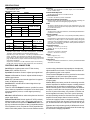
Frequency Response (ref 1 kHz)
Distortion
30 to 20,000 Hz, ±2 dB
0.4% THD, 30 to 20,000 Hz at +15 dBm output; 0.5% or less IM distortion at +15 dBm output
Voltage Gain (at 1 kHz)
INPUT
Common Mode Rejection
OUTPUT
LINE
MICROPHONE
65 dB minimum with input of - 20 dBV at 100 Hz
LINK
Mic
90 dB
40 dB
70 dB
Line
40 dB
-10 dB
20 dB
Link
20 dB
-30dB
--
Control Interaction
Less than 1 dB with any control combination
Overload and Shorting Protection
Shorting outputs, even for prolonged periods, willcause no damage; microphone input will not be damaged by signals up to 3V
Phase
Inputs
INPUT
IMPEDANCE (at 1 kHz)
FOR USE WITH
All outputs in phase with input. Pin 2 is “high” with respect to pin 3; pin
1 is ground. Tips of link input and output phone jacks are in phase with
pin 2 of XLR connectors.
INPUT CLIPPING
LEVEL AT 1kHz
ACTUAL
Mic
150 Ω
1 kΩ
-62 to -6 dBV*
Line
less than 10 kΩ
66 kΩ
-12 to + 44 dBV*
Link
more than 5 kΩ
24 kΩ
+8 dBV
Phantom Power
30 VDC nominal, 3.3k series resistance, automatically disabled with input switch in Line position
Operating Voltage
AC Operation: 120 or 240 VAC ± 10% (internally selectable), 50/60 Hz,
5.5W
DC Operation: 27 VDC nominal at 16 mA typical no- signal, 22 mA typical at 0 VU (+4 dBm) output; 21.5 VDC minimum; battery life approximately 20 hours with alkaline batteries at +4 dBm output in continuous
use; three 9 volt batteries, type NEDA 1604A (Duracell MN1604 or
Eveready 522 recommended)
*Dependent on input control setting
Outputs
INPUT
IMPEDANCE (at 1 kHz)
FOR USE WITH
ACTUAL
INPUT CLIPPING
LEVEL AT 1kHz
Mic
150 Ω
2Ω
-34 dBV
Line
600 Ω
185 Ω
+16 dBV
Link
600 Ω or greater
100 Ω or less
+16 dBV
Temperature Range
Operating: -18° to 57°C (0° to 135°F)
Storage: -29° to 71°C (-20° to 160°F)
Dimensions
Noise
79.5 mm H x 310 mm W x 230 mm D
(3-1/8 in, x 12-7/32 in. x 9-1/16 in.)
Equivalent Input Noise: -129 dBV (low-impedance microphone,
150 Ohms, 300 to 20,000 Hz) into 600 ohm load at full gain
Equivalent Input Hum and Noise: -127 dBV (low-impedance microphone, 150 Ohms, 20 to 20,000 Hz) into 600 ohm load at full gain
Output Noise: -90 dBV maximum (output control full counterclockwise
[off]), -65 dBV maximum (output control full clockwise [on]) (input control
down, 300 to 20,000 Hz)
Output Hum and Noise: -75 dBV maximum (output control down), 65 dBV max. (output control up, input control down, 20 to 20,000 Hz)
Weight
Net: 2.75 kg (6 Ib 1 oz.)
Packaged: 3.15 kg (6 Ib 15 oz.)
Certifications
Listed by Underwriters Laboratories. Inc.; listed by Canadian Standards
Association as Certified
CONTROLS AND CONNECTORS
on when using unbalanced low-impedance microphones;
objectionable hum will result. Turn the Phantom switch off
when phantom power is not required.
On⋅Off Switch: applies power to the FP16A circuitry
Power LED: Indicates unit is on.
Input Gain Screwdriver Control: adjusts input signal level.
Three-Socket XLR Input connector: provides for connection
to microphone or line level input signal sources.
Output 1-6 Screwdriver Control: adjusts individual output
channel signal levels.
Input Mic/Line Slide Switch: selects microphone or line-level input signals.
Norm LED: indicates when internal signal level is approximately 25 dB below clipping.
Link In, Out Phone Jacks: provide for connecting more distribution amplifiers for additional outputs, or adding external
equipment such as equalizers, compressors, or limiters.
When connecting two or more FP16As together for additional outputs, connect the Link Out jack of the "master" unit to
the Link In jacks of the others. Any number of FP16As can
be tied together in this way. The Link In jack is input-only,
and has switching contacts to disconnect the input signal
amplifier from the output channel volume controls.
Overload LED: indicates when internal signal level approaches clipping.
Three-Pin XLR 1-6 Output Connectors: provide for connection to either low-impedance microphone or line level inputs
of power amplifiers, mixers, or other signal processing
equipment.
Mic/Line 1-6 Slide Switches: select microphone or line level
output signal levels.
Connect an equalizer, limiter or compressor to the FP16A by
connecting the FP16A Link Out jack to the external unit's input, and the external unit's output to the FP16A Link In jack.
Phantom On-Off Slide Switch: applies 27 VDC (nominal)
phantom power to pins 2 and 3 of the input connector for
use with condenser microphones. IMPORTANT: Make certain any condenser microphone used is compatible with the
FP16A phantom circuit, and that the FP16A input Mic/Line
switch is in the Mic position. Do not turn the Phantom switch
Signals at the Link jacks are typically 10 dB below line level.
The Link In input impedance is greater than 20 kΩ and may
be considered a bridging impedance.
2