1
Wood-Mizer® Sawmill
Safety, Setup, Operation
& Maintenance Manual
1992 LT30HD
1992 LT40HD
!
rev. C7 - F7
rev. C7 - F7
Safety is our #1 concern! Read and understand all
safety information and instructions before operating, setting up or maintaining this machine.
October 1996
Form #625
This manual is to replace or to be used with all previous information received on the
Wood-Mizer®* sawmill. All future mailings will be an addition to or a revision of individual
sections of this manual as we obtain new information.
The information and instructions given in this manual do not amend or extend the limited
warranties for the equipment given at the time of purchase.
If You Need To Order Parts...
From the continental U.S., call our toll-free Parts hotline at 1-800-448-7881. Please have
the vehicle identification number and your customer number ready when you call.
Wood-Mizer will accept these methods of payment:
Visa, Mastercard, or Select Purchase
COD
Prepayment
Net 15 (with approved credit)
Be aware that shipping and handling charges may apply. Handling charges are based on
size and quantity of order. In most cases, items will ship on the day they are ordered.
Second Day and Next Day shipping are available at additional cost.
If your sawmill was purchased outside of the United States, contact your distributor for
replacement parts.
ii
HD92doc042701
If You Need Service...
From the continental U.S., call us toll-free at 1-800-525-8100. Ask to speak with a Customer Service Representative. Please have your vehicle identification number and your
customer number ready when you call. The Service Representative can help you with
questions about alignment of your mill, blade sharpening, or cutting a particular species of
wood. He also can schedule you for a service call.
Office Hours:
All times are Eastern Standard Time. Please remember that Indiana does not go on Daylight Savings Time in the summer.
Monday - Friday8 a.m. to 5 p.m.
Saturday8 a.m. to 4 p.m.
If your sawmill was purchased outside the United States, contact the distributor for service.
!
IMPORTANT! Read the entire Operator's Manual before
operating the sawmill. Take notice of all safety warnings
throughout this manual and those posted on the machine.
Keep this manual with this machine at all times, regardless
of ownership.
*Wood-Mizer® is a registered trademark of Wood-Mizer Products, Inc.
HD92doc042701iii
Your Vehicle Identification Number And
Customer Number
Each Wood-Mizer sawmill has a 17-digit Vehicle Identification Number (VIN). See the figure below for VIN locations. See the chart at the right for VIN description.
Each sawmill is also identified with a model number which includes the base model and
the engine/motor configuration. An ’s’ after the model number indicates the model is
approved for sale in countries that have adopted German "Gerprüfte Sicherheit: (G.S.)
safety standards. The model number is located on the middle blade housing cover. See
the figure at the right for a description of the model number.
When you pick up your mill, you will receive a customer number. Both the VIN and your
customer number expedite our service to you. Please write these numbers below so you
have quick, easy access to them.
VIN: ___________________________
Customer No: ___________________
Model No: ______________________
VEHICLE IDENTIFICATION NUMBER LOCATIONS.
iv
HD92doc042701
V.I.N. DESCRIPTION.
MODEL NUMBER DESCRIPTION.
v
HD92doc042701
Table of Contents
SECTION 1
1.1
1.2
1.3
1.4
1.5
1.6
1.7
1.8
1.9
1.10
1.11
1.12
Table of Contents
SAFETY & GENERAL INFORMATION
1-1
Blade Handling .......................................................................................................... 1-1
Sawmill Setup............................................................................................................ 1-1
Sawmill Operation..................................................................................................... 1-2
Belt Sizes ................................................................................................................... 1-4
Blade Sizes ................................................................................................................ 1-5
Cutting Capacity ........................................................................................................ 1-6
Engine/Motor Specifications ..................................................................................... 1-7
Overall Dimensions ................................................................................................... 1-8
Components ............................................................................................................... 1-9
Hydraulic Schematic ............................................................................................... 1-10
Hydraulic Components............................................................................................ 1-12
Hydraulic Hoses ...................................................................................................... 1-14
SECTION 2
2.1
2.2
2.3
2.4
2.5
2.6
2.7
2.8
2.9
2.10
2.11
2.12
2.13
2.14
2.15
2.16
2.17
2.18
2.19
2.20
Section-Page
SETUP & OPERATION
2-1
Stationary Sawmill Setup .......................................................................................... 2-1
Portable Sawmill Setup ............................................................................................. 2-2
Preparing The Sawmill For Operation ...................................................................... 2-5
Replacing The Blade ................................................................................................. 2-6
Tensioning The Blade................................................................................................ 2-7
Tracking The Blade ................................................................................................... 2-8
Starting The Engine (or Motor) ............................................................................... 2-10
Hydraulic Control Operation ................................................................................... 2-11
Loading, Turning, And Clamping Logs .................................................................. 2-15
Clamp Extension .................................................................................................... 2-18
Up/Down Operation ................................................................................................ 2-19
Blade Guide Arm Operation.................................................................................... 2-20
Clutch/Brake Operation........................................................................................... 2-21
Power Feed Operation ............................................................................................. 2-22
Cutting The Log ...................................................................................................... 2-24
Edging...................................................................................................................... 2-25
Blade Height Sight Gauge ....................................................................................... 2-26
Blade Height Scale .................................................................................................. 2-27
Water Lube Operation ............................................................................................. 2-30
Preparing The Sawmill For Towing ........................................................................ 2-31
HD92doc042701
i
Table of Contents
SECTION 3
3.1
3.2
3.3
3.4
3.5
3.6
3.7
3.8
3.9
3.10
3.11
3.12
3.13
3.14
3.15
3.16
3.17
Table of Contents
MAINTENANCE
3-1
Wear Life................................................................................................................... 3-1
Blade Guides ............................................................................................................. 3-2
Hydraulic Log Loader ............................................................................................... 3-3
Blade Housing ........................................................................................................... 3-4
Carriage Track, Wiper & Scrapers ............................................................................ 3-5
Track Rollers ............................................................................................................. 3-6
Vertical Mast Rails .................................................................................................... 3-7
Drum Switches .......................................................................................................... 3-8
Miscellaneous Lubrication ........................................................................................ 3-9
Blade Tensioner....................................................................................................... 3-10
Blade Wheel Belts ................................................................................................... 3-11
Brake Strap Adjustment .......................................................................................... 3-12
Hydraulic System .................................................................................................... 3-14
Drive Bearing .......................................................................................................... 3-16
Up/Down System..................................................................................................... 3-17
Power Feed .............................................................................................................. 3-20
Miscellaneous Maintenance .................................................................................... 3-22
SECTION 4
4.1
4.2
4.3
4.4
4.5
4.6
4.7
4.8
4.9
4.10
Section-Page
TROUBLESHOOTING GUIDE
4-1
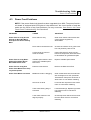
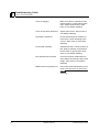
Sawing Problems ....................................................................................................... 4-1
Electrical Problems.................................................................................................... 4-3
Power Feed Problems ................................................................................................ 4-5
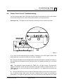
Power Feed Circuit Troubleshooting......................................................................... 4-7
Hydraulic Problems ................................................................................................... 4-9
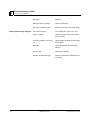
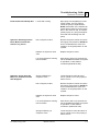
Engine/Motor and Drive Pulleys Alignment........................................................... 4-12
Power Feed Variable Speed Switch Test................................................................. 4-13
Power Feed Preliminary Test .................................................................................. 4-14
Power Feed Mechanical Test................................................................................... 4-15
Hydraulic Pressure Test........................................................................................... 4-16
HD92doc042701
ii
Table of Contents
SECTION 5
5.1
5.2
5.3
5.4
5.5
5.6
5.7
5.8
5.9
5.10
5.11
5.12
5.13
5.14
5.15
5.16
5.17
5.18
5.19
5.20
Table of Contents
Section-Page
SAWMILL ALIGNMENT
5-1
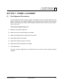
Pre-Alignment Procedures......................................................................................... 5-1
Frame Setup............................................................................................................... 5-2
Blade Installation And Alignment............................................................................. 5-3
Saw Head Slide Pad Adjustment............................................................................... 5-5
Adjusting The Lower Track Rollers.......................................................................... 5-7
Adjusting Main Bed Rails To Blade ......................................................................... 5-9
Blade Guide Arm Vertical Adjustment ................................................................... 5-11
Blade Guide Arm Horizontal Adjustment............................................................... 5-12
Aligning The Blade Guides ..................................................................................... 5-14
Blade Deflection ...................................................................................................... 5-15
Blade Guide Vertical Tilt Adjustment..................................................................... 5-16
Blade Guide Spacing ............................................................................................... 5-18
Horizontal Tilt Adjustment...................................................................................... 5-19
Horizontal Adjustment Of Side Supports................................................................ 5-20
Vertical Adjustment Of Side Supports .................................................................... 5-21
Clamp Stop Adjustment .......................................................................................... 5-22
Aligning The Pivot Bed Rails.................................................................................. 5-23
Sight Gauge Adjustment.......................................................................................... 5-25
Saw Head Tilt .......................................................................................................... 5-26
Blade Height Scale Adjustment............................................................................... 5-27
HD92doc042701
iii
Safety & General Information
Blade Handling
1
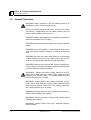
SECTION 1 SAFETY & GENERAL INFORMATION
This symbol calls your attention to instructions concerning your personal safety. Be sure
to observe and follow these instructions. This symbol accompanies a signal word. The
word DANGER refers to hazards that can cause death or serious, irreversible personal
injury. The word WARNING suggests a safety hazard that can cause personal injury.
CAUTION refers to hazards that can cause damage to the equipment or property only.
Read all safety instructions before operating this equipment and observe all safety warnings!
Safety instructions are listed in this section by the following operations:
1.1
Blade Handling
Sawmill Setup
Sawmill Operation
Blade Handling
WARNING! Always wear gloves and eye protection when
handling bandsaw blades. Keep all persons away from
area when coiling or carrying a blade.
1.2
Sawmill Setup
DANGER! Chock the trailer wheels to prevent movement
before unhitching it from the towing vehicle.
DANGER! Put front outrigger down before moving cutting
head from the rest position.
WARNING! Do not set up the mill on ground with more than
a 10 degree incline. If setup on an incline is necessary, dig
out areas for outrigger legs to keep mill level. Setting up the
mill on an incline could cause it to tip over!
Safety & General Information
HD92doc042701
1-1
Safety & General Information
1 Sawmill Operation
1.3
Sawmill Operation
DANGER! Never operate or tow the sawmill without all
guards and covers in place and secured.
Be sure the blade housing and pulley covers are in place
and secure. If applicable, use the safety retainer pin and
cable to fasten blade housing covers.
DANGER! Always disengage the clutch/brake mechanism
whenever the sawmill is not cutting.
DANGER! Always keep hands away from moving bandsaw
blade.
DANGER! Keep all persons a safe distance away from
work area when operating sawmill or loading and turning
logs.
DANGER! Be sure the power feed switch is in the neutral
position before turning the key switch to the ON or ACC
position. This prevents unwanted carriage movement.
DANGER! Check to be sure the saw head is resting firmly
on the rest pin and mast rail stops and that the safety chain
is secured before towing the sawmill.
WARNING! Always secure the cutting head with a 5/16”
chain with a least 1900 lbs. working load capacity before
adjusting the up/down chain. The cutting head may fall,
causing severe injury or death.
WARNING! Always secure the cutting head with a 5/16”
chain with a least 1900 lbs. working load capacity before
removing the up/down motor belt. The cutting head may
fall, causing severe injury or death.
WARNING! Always wear eye, ear, respiration, and foot protection when operating the sawmill.
WARNING! Secure all loose clothing and jewelry before
operating the sawmill.
WARNING! Always make sure log is clamped securely
before sawing.
1-2
HD92doc042701
Safety & General Information
Safety & General Information
Sawmill Operation
1
CAUTION! Always be sure that all safety warning decals
are clean and readable. Replace all damaged warning
decals. Contact your local distributor, or call your Customer
Service Representative to order more decals.
CAUTION! Be sure the pivot end rails, turning arm, clamp,
and toe boards are out of the way before loading a log onto
the bed. Also, be sure the cutting head is moved far enough
forward so the log does not hit it.
CAUTION! Failure to fully extend the log clamp before towing can result in damage to the clamping assembly during
towing.
!
IMPORTANT! It is always the owner's responsibility to comply with all applicable federal, state and local laws, rules
and regulations regarding the ownership, operation and
towing of your Wood-Mizer sawmill. All Wood-Mizer mill
owners are encouraged to become thoroughly familiar with
these applicable laws and comply with them fully while
using or towing the mill.
Always properly dispose of all sawing byproducts, including
sawdust and other debris.
Safety & General Information
HD92doc042701
1-3
Safety & General Information
1 Belt Sizes
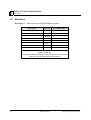
1.4
Belt Sizes
See Table 1-1. Belt sizes for the LT30HD/40HD are shown.
Description
Belt Size
Wood-Mizer Part #
24hp Gas Engine Drive Belt
2BX742
P10277-2
20hp Diesel Engine Drive Belt
2BX682
P12139-2
15hp Electric Motor Drive Belt
2BX702
P04857-2
Alternator Belt (G24)
A33
P11542
Alternator Belt (D20/E15)
A30
P11628
Blade Pulley Belts
B57
1
P04185
Power Feed Drive Belt
4L280
P04031
Up/Down Drive Belt
3L290
P04349
1
To insure proper blade tracking, use Goodyear, Dayco Super II, or
Browning belts only.
2Two belts originally supplied on machines prior to rev E3. Replace
with one common-backed belt as listed above.
TABLE 1-1
1-4
HD92doc042701
Safety & General Information
Safety & General Information
Blade Sizes
1.5
1
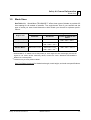
Blade Sizes
See Table 1-2. Wood-Mizer TRU•SHARP™ offers three types of blades to provide efficient sawing for all models of sawmills. The engine/motor size of your sawmill and the
type of wood you saw should determine which blade you choose for optimum performance.
Gas/Diesel
Engine Size
Recommended Blade For Sawing:
Softwood
Hardwood
Frozen or Hard-to-Cut
Wood
5 hp - 14hp
.042 x 7/8 x 1 1/4”
.035 x 7/8 x 1 1/4”
.045 x 7/8 x 1 1/4” F 1
16hp or more
.045 x 7/8 x 1 1/2”
.042 x 7/8 x 1 1/4”
.045 x 7/8 x 1 1/2” 2
.045 x 7/8” x 1 1/4” F1
Electric Motor
.045 x 7/8 x 1 1/2”
.042 x 7/8 x 1 1/4”
.045 x 7/8 x 1 1/2” 2
.045 x 7/8 x 1 1/4” F1
TABLE 1-2
1
TRU•SHARP™ “F” blades use a 9/29 profile (9° hook angle and 29° back angle) and are designed to cut frozen and/or extremely dense, hard-to-cut wood. Standard TRU•SHARP™
blades use a 10/30 profile.
2
Customer may choose preferred blade.
See The Blade Handbook for blade hook angle, tooth height, and tooth set specifications.
Safety & General Information
HD92doc042701
1-5
Safety & General Information
1 Cutting Capacity
1.6
Cutting Capacity
See Table 1-3.
below.
The log size capacities of the LT30HD and LT40HD sawmills are listed
Max.
Diameter 1
Max.
Length 1
LT30HD
36" (91.5 cm) 2
16' 8" (5.1 m)
LT40HD
36" (91.5 cm) 2
21' (6.4 m)
LT30HD with Optional 12'
Bed Extension 3
36" (91.5 cm) 2
28' 8" (8.7 m)
LT40HD with Optional
12' Bed Extension 3
36" (91.5 cm) 2
33' (10.1 m)
TABLE 1-3
1
Maximum log capacity for a basic mill is 4400 lbs. (1996 Kg).
Maximum diameter capacity prior to revision C8 is 32"
3
Logs over 4400 lbs. must be distributed so that neither the basic mill or extension is loaded beyond the 4400 lb. maiximum weight rating. Loading
logs heavier than 4400 lbs. (1996 Kg.) on a mill equipped with bed extension requires auxilliary log handling equipment.
2
See Table 1-4. The production capacity of the LT30HD and LT40HD sawmills is listed
below. Productivity is based on sawing 1" lumber. The low end of the range is based on a
single operator with no support equipment. The high end of the range is based on two
operators with support equipment.
1-6
Model
Production Capacity
LT30HD/40HD 24hp gas engine
2,000 - 3,400 bdft./day
LT30HD/40HD 15hp electric motor
2,000 - 3,400 bdft./day
LT30HD/40HD 20hp diesel engine
2,000 - 3,200 bdft./day
HD92doc042701
Safety & General Information
Safety & General Information
Engine/Motor Specifications
1.7
1
Engine/Motor Specifications
See Table 1-5.
listed below.
The power options available for the LT30HD and LT40HD sawmills are
Engine/Motor
Type
Manufacturer
Model
Number
24HP Gasoline
Onan
P224
20HP Diesel
Acme
ADX740
15HP Electric
Baldor
Custom
TABLE 1-5
Safety & General Information
HD92doc042701
1-7
Safety & General Information
1 Overall Dimensions
1.8
Overall Dimensions
See Table 1-6. The overall dimensions of the LT30HD sawmill are listed below.
LT30HD
LT30HD with Surge
Brake Trailer Pkg.
Length
19' 11" (5.3 m)
21' 9" (6.6 m)
Width
8' (2.4 m)
8' 2" (2.5 m)
Height
7' 6" (2.3 m)
7' 6" (2.3 m)
Weight
2433 lbs. (1105 Kg)
2780 lbs. (1262 Kg)
TABLE 1-6
See Table 1-7. The overall dimensions of the LT40HD sawmill are listed below.
1-8
LT40HD
LT40HD with Surge Brake
Trailer Pkg.
Length
24' 4" (7.4 m)
26' 2" (8.0 m)
Width
8' (2.4 m)
8' 2" (2.5 m)
Height
7' 6" (2.3 m)
7' 6" (2.3 m)
Weight
2513 lbs. (1141 Kg)
2860 lbs. (1298 Kg)
HD92doc042701
Safety & General Information
Safety & General Information
Components
1.9
1
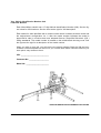
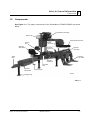
Components
See Figure 1-1. The major components of the Wood-Mizer LT30HD/LT40HD are shown
below.
Engine/Drive Assembly
Water Lube
Outer Blade Guide Arm
Blade
Tensioner
Control
Box
Operator
Seat Option
Hydraulic
Log Turner
Side Support
Hydraulic
Log Clamp
Hydraulic
Log Loader
Trailer
Hitch
Hydraulic
Toe Board
Pivot Bed
Rail
Hydraulic
Control Box
Manual Winch
HD0001
Outrigger Leg
FIG. 1-1
Safety & General Information
HD92doc042701
1-9
Safety & General Information
1 Hydraulic Schematic
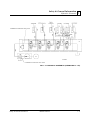
1.10 Hydraulic Schematic
FIG. 1-2 HYDRAULIC SCHEMATIC (REVISIONS E7+).
1-10
HD92doc042701
Safety & General Information
Safety & General Information
Hydraulic Schematic
1
FIG. 1-3 HYDRAULIC SCHEMATIC (REVISIONS C7 - E6).
Safety & General Information
HD92doc042701
1-11
Safety & General Information
1 Hydraulic Components
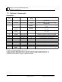
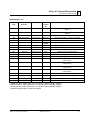
1.11 Hydraulic Components
REVISIONS E7+
Component
Mfg. Part No. Manufacturer
Wood-Mizer
Part.#
Description
C1
A09665
Wood-Mizer
A09665
Hydraulic Cylinder, 1.5" Bore X 3.5" Stroke,
Spring Return
C2
A09665
Wood-Mizer
A09665
Hydraulic Cylinder, 1.5" Bore X 3.5" Stroke,
Spring Return
C3
P12847
J-D Hydraulic
P12847 1
Hydraulic Cylinder, 3" Bore X 8" Stroke (Rev.
F5+)
TQ3008
Q0002
Monarch Can.
P09128 2
Hydraulic Cylinder, 3" Bore X 8" Stroke (Rev.
E7 - F4)
TQ3008
Q0002
Monarch Can.
P09128 2
Hydraulic Cylinder, 3" Bore X 8" Stroke (Rev.
E7 - F4)
C5
P12845
J-D Hydraulic
P12845 3
Hydraulic Cylinder, 2" Bore X 6" Stroke
C6
P12846
J-D Hydraulic
P12846 4
Hydraulic Cylinder, 2.5" Bore X 6" Stroke
C7
P12847
J-D Hydraulic
P12847 1
Hydraulic Cylinder, 3" Bore X 8" Stroke
Monarch Hyd.
N/A
Hydraulic Pump, Motor Driven
P1
SV1
A09207
Wood-Mizer
A09207
Sequence Valve
SV2
A09207
Wood-Mizer
A09207
Sequence Valve
V1
07129
Monarch Hyd.
P12700
Valve, 5-Valve Salami
VF1
28000-502-2.5
Vonberg
P11566
Valve, Hydraulic Velocity Fuse
VF2
28000-502-2.5
Vonberg
P11566
Valve, Hydraulic Velocity Fuse
M
08058 5
Monarch Hyd.
P09955
Motor, Hydraulic Pump
1 Welded
cylinder P12847 replaces tie rod cylinder P09128 originally supplied before Rev. F5.
tie rod cylinder P09128 for Rev. C7 - F4.
3 Welded cylinder P12845 replaces tie rod cylinder P09125 originally supplied before Rev. F5.
4 Welded cylinder P12846 replaces tie rod cylinder P09127 originally supplied before Rev. F5
5 Replaces Monarch #08111 originally supplied before 8/94.
2 Use
1-12
HD92doc042701
Safety & General Information
Safety & General Information
Hydraulic Components
1
REVISIONS C7 - E6
Component
Manufacturer
Part No.
Manufacturer Wood-Miz
er Part
No.
C1
A09665
Wood-Mizer
A09665
Hydraulic Cylinder, 1.5" Bore X 3.5" Stroke, Spring
Return
C2
A09665
Wood-Mizer
A09665
Hydraulic Cylinder, 1.5" Bore X 3.5" Stroke, Spring
Return
C3
TQ3008 Q0002
Monarch Can.
P09128
Hydraulic Cylinder, 3" Bore X 8" Stroke
C4
TQ3008 Q0002
Monarch Can.
P09128
Hydraulic Cylinder, 3" Bore X 8" Stroke
1
Description
Hydraulic Cylinder, 2" Bore X 6" Stroke
C5
P12845
J-D Hydraulic
P12845
C6
P12846
J-D Hydraulic
P12846 2
Hydraulic Cylinder, 2.5" Bore X 6" Stroke
C7
P12847
J-D Hydraulic
P12847 3
Hydraulic Cylinder, 3" Bore X 8" Stroke
CV1
A11687
Wood-Mizer
A11687
Check Valve
CV2
A11687
Wood-Mizer
A11687
Check Valve
P1
O2414
Monarch Hyd.
N/A
Hydraulic Pump, Motor Driven
SV1
A09207
Wood-Mizer
A09207
Sequence Valve
SV2
A09207
Wood-Mizer
A09207
Sequence Valve
V1
00647
Monarch Hyd.
P11581
Valve, 4-way Manually Operated (Integral Part Of
P/N P10371)
V2
00524
Monarch Hyd.
P10143
Valve, 4-way Manually Operated (Integral Part Of
P/N P10371)
V3
00524
Monarch Hyd.
P10143
Valve, 4-way Manually Operated (Integral Part Of
P/N P10371)
V4
00524
Monarch Hyd.
P10143
Valve, 4-way Manually Operated (Integral Part Of
P/N P10371)
V5
A09680
Wood-Mizer
A09680
Dump Valve, Manually Operated
VF1
28000-502-2.5
Vonberg
P11566
Valve, Hydraulic Velocity Fuse
VF2
28000-502-2.5
Vonberg
P11566
Valve, Hydraulic Velocity Fuse
M
08058 4
Monarch Hyd.
P09955
Motor, Hydraulic Pump
1
Welded cylinder P12845 replaces tie rod cylinder P09125 originally supplied.
Welded cylinder P12846 replaces tie rod cylinder P09127 originally supplied.
3
Welded cylinder P12847 replaces tie rod cylinder P09128 originally supplied.
4
Replaces Monarch #08111 originally supplied.
2
Safety & General Information
HD92doc042701
1-13
Safety & General Information
1 Hydraulic Hoses
1.12 Hydraulic Hoses
REVISIONS F5+
Component
Color
Code
Application
Wood-Mize
r Part No.
Description
H3
Plain
Log Turner Cylinder Base
P12533
Hose, 1/4" X 14" Hydraulic
W/Fittings
H4
Orange
Log Turner Cylinder Top
P12535
Hose, 1/4" X 27" Hydraulic
W/Fittings
H5
Yellow
Front Toe Board (LT30HD)
P12539
Hose, 1/4" X 84" Hydraulic
W/Fittings
Yellow
Front Toe Board (LT40HD)
P12541
Hose, 1/4" X 106" Hydraulic
W/Fittings
Pink
Side Support Cylinder Base
(LT30HD)
P12545
Hose, 1/4" X 151" Hydraulic
W/Fittings
Pink
Side Support Cylinder Base
(LT40HD)
P12549
Hose, 1/4" X 173" Hydraulic
W/Fittings
White
Clamp Cylinder Top (LT30HD)
P12544
Hose, 1/4" X 142" Hydraulic
W/Fittings
White
Clamp Cylinder Top (LT40HD)
P12548
Hose, 1/4" X 164" Hydraulic
W/Fittings
Dark
Orange
Clamp Cylinder Base (LT30HD)
P12543
Hose, 1/4" X 135" Hydraulic
W/Fittings
Dark
Orange
Clamp Cylinder Base (LT40HD)
P12546
Hose, 1/4" X 157" Hydraulic
W/Fittings
Plain
Side Support Cylinder Top
(LT30HD)
P12547
Hose, 1/4" X 159" Hydraulic
W/Fittings
Plain
Side Support Cylinder Top
(LT40HD)
P12550
Hose, 1/4" X 186" Hydraulic
W/Fittings
Purple
Rear Toe Board (LT30HD)
P12549
Hose, 1/4" X 173" Hydraulic
W/Fittings
Purple
Rear Toe Board (LT40HD)
P12551
Hose, 1/4" X 197" Hydraulic
W/Fittings
H11
Green
Loading Arm Branch Top
P12537
Hose, 1/4" X 50" Hydraulic
W/Fittings
H12
Green
Loading Arm Branch Top
P12537
Hose, 1/4" X 50" Hydraulic
W/Fittings
H13
Yellow
Loading Arm Branch Base
P12538
Hose, 1/4" X 55" Hydraulic
W/Fittings
H14
Yellow
Loading Arm Branch Base
P12538
Hose, 1/4" X 55" Hydraulic
W/Fittings
H6
H7
H8
H9
H10
1-14
HD92doc042701
Safety & General Information
Safety & General Information
Hydraulic Hoses
1
REVISIONS F5+
H15
H16
H17
Blue
Loading Arm Cylinder Top
(LT30HD)
P12545
Hose, 1/4" X 151" Hydraulic
W/Fittings
Blue
Loading Arm Cylinder Top
(LT40HD)
P12549
Hose, 1/4" X 173" Hydraulic
W/Fittings
Red
Loading Arm Cylinder Bottom
(LT30HD)
P12545
Hose, 1/4" X 151" Hydraulic
W/Fittings
Red
Loading Arm Cylinder Bottom
(LT40HD)
P12549
Hose, 1/4" X 173" Hydraulic
W/Fittings
None
Hydraulic Pump To Valve
P12705
Hose, 3/8" X 22" Hydraulic
W/Fittings
Safety & General Information
HD92doc042701
1-15
Safety & General Information
1 Hydraulic Hoses
REVISIONS C7 - F4
Component
Color
Code
Application
Wood-Mize
r Part No.
Description
H1
Brown
Toe Board Return (Rev. C7- E6
Only)
P12534
Hose, 1/4" X 22" Hydraulic
W/Fittings
H2
Brown
Toe Board Return (Rev. C7- E6
Only)
P12534
Hose, 1/4" X 22" Hydraulic
W/Fittings
H3
Gold
Log Turner Cylinder Base
P12533
Hose, 1/4" X 14" Hydraulic
W/Fittings
H4
Grey
Log Turner Cylinder Top
P12535
Hose, 1/4" X 27" Hydraulic
W/Fittings
H5
Bright Yellow
Front Toe Board (LT30HD)
P12539
Hose, 1/4" X 84" Hydraulic
W/Fittings
Bright Yellow
Front Toe Board (LT40HD)
P12541
Hose, 1/4" X 106" Hydraulic
W/Fittings
Silver
Side Support Cylinder Base
(LT30HD)
P12545
Hose, 1/4" X 151" Hydraulic
W/Fittings
Silver
Side Support Cylinder Base
(LT40HD)
P12549
Hose, 1/4" X 173" Hydraulic
W/Fittings
White
Clamp Cylinder Top (LT30HD)
P12544
Hose, 1/4" X 142" Hydraulic
W/Fittings
White
Clamp Cylinder Top (LT40HD)
P12548
Hose, 1/4" X 164" Hydraulic
W/Fittings
Orange
Clamp Cylinder Base (LT30HD)
P12543
Hose, 1/4" X 135" Hydraulic
W/Fittings
Orange
Clamp Cylinder Base (LT40HD)
P12546
Hose, 1/4" X 157" Hydraulic
W/Fittings
Plain
Side Support Cylinder Top
(LT30HD)
P12547
Hose, 1/4" X 159" Hydraulic
W/Fittings
Plain
Side Support Cylinder Top
(LT40HD)
P12550
Hose, 1/4" X 186" Hydraulic
W/Fittings
Black
Rear Toe Board (LT30HD)
P12549
Hose, 1/4" X 173" Hydraulic
W/Fittings
Black
Rear Toe Board (LT40HD)
P12551
Hose, 1/4" X 208" Hydraulic
W/Fittings
H11
Dark
Green
Loading Arm Branch Top
P12537
Hose, 1/4" X 52" Hydraulic
W/Fittings
H12
Dark
Green
Loading Arm Branch Top
P12537
Hose, 1/4" X 52" Hydraulic
W/Fittings
H13
Dark Yellow
Loading Arm Branch Base
P12538
Hose, 1/4" X 55" Hydraulic
W/Fittings
H14
Dark Yellow
Loading Arm Branch Base
P12538
Hose, 1/4" X 55" Hydraulic
W/Fittings
H6
H7
H8
H9
H10
1-16
HD92doc042701
Safety & General Information
Safety & General Information
Hydraulic Hoses
1
REVISIONS C7 - F4
H15
H16
H17
Blue
Loading Arm Cylinder Top
(LT30HD)
P12545
Hose, 1/4" X 151" Hydraulic
W/Fittings
Blue
Loading Arm Cylinder Top
(LT40HD)
P12549
Hose, 1/4" X 173" Hydraulic
W/Fittings
Red
Loading Arm Cylinder Bottom
(LT30HD)
P12545
Hose, 1/4" X 151" Hydraulic
W/Fittings
Red
Loading Arm Cylinder Bottom
(LT40HD)
P12549
Hose, 1/4" X 173" Hydraulic
W/Fittings
None
Hydraulic Pump To Valve (Rev.
E7+Only)
P12705
Hose, 3/8" X 22" Hydraulic
W/Fittings
Safety & General Information
HD92doc042701
1-17
Setup & Operation
Stationary Sawmill Setup
2
SECTION 2 SETUP & OPERATION
2.1
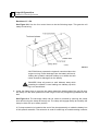
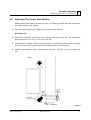
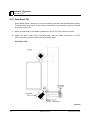
Stationary Sawmill Setup
See Figure 2-1. Set up the mill on firm footing. Level by eye. Fasten the mill to the floor or
platform, or tie down to footing to stop any creep after prolonged use.
NOTE: Make sure the unit is level before securing. It IS possible to twist the mill frame by
jacking one foot higher than the others.
DANGER! Do not operate a stationary sawmill without the
feet securely fastened to the floor. If the feet are not
securely fastened, loading and turning large logs could
cause the sawmill to tip over.
FIG. 2-1
*NOTE Rear leg standard on LT40/LT40HD after 3/92. Rear leg or outrigger may be retrofitted to previous
models.
Setup & Operation
HD92doc042701
2-1
Setup & Operation
2 Portable Sawmill Setup
2.2
Portable Sawmill Setup
WARNING! If the sawmill is to be set up on inclines of more
than 10 degrees, put blocks under one side of the mill, or
dig holes to prevent the mill from tipping over.
DANGER! Chock the trailer wheels to prevent movement
before unhitching it from the towing vehicle.
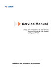
1. Unhitch the mill from the vehicle.
See Figure 2-2.
FIG. 2-2
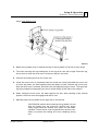
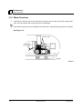
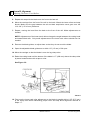
2. Lower and set the front three outriggers. Lift the weight from the locking pin using the jack
handle. Pull the locking pin to release the outrigger and lower the outrigger as necessary.
Secure with the locking pin.
DANGER! Put front outrigger down before moving cutting
head from the rest position.
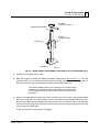
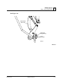
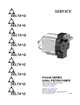
For Fine Adjust Outriggers (FAOs), lower the outrigger as close to the ground as possible,
then secure in place with the locking pin. Adjust the outrigger base so that it contacts the
ground. To adjust, use the provided wrench to turn the height adjustment nut. Turn clockwise to lower. Turn counterclockwise to raise. Maximum adjustment available is 1 1/2”
(3.8 cm).
CAUTION! Do not adjust the FAO outrigger base height
while there is weight on the FAO. Damage to the FAO may
result.
2-2
HD92doc042701
Setup & Operation
Setup & Operation
Portable Sawmill Setup
2
Provided
Adjustment Wrench
Height Adjustment Nut
Existing
Outrigger Guide
Locking Pin
FAO Base
SM0213
FIG. 2-2. BASE HEIGHT ADJUSTMENT (FOR FINE ADJUST OUTRIGGER ONLY).
3. Unhook the carriage safety chain.
4. Start the engine to enable the battery-operated accessories (See Section 2.7). Use the
up/down switch on the control panel to raise the cutting head from the carriage rest pin.
Remove the locking pin and swing the rest pin down below bed level.
CAUTION! Always make sure the engine is running before
operating the sawmill controls. Operating the controls without the engine running will result in power drainage from
the battery.
5. Use the carriage fwd/rev switch (left side of control box) to move the cutting head toward
the front end of the mill. The hydraulic control levers become operational when the contacts at the bottom of the carriage touch the power strip on the frame tube. The hydraulic
control levers will only work when the cutting head is close enough to the front end of the
mill to touch the power strip.
Lower and set the remaining rear outriggers.
Setup & Operation
HD92doc042701
2-3
Setup & Operation
2 Portable Sawmill Setup
6. Level the sawmill by adjusting the outriggers to raise or lower each end of the sawmill.
Adjust all outriggers evenly to avoid twisting the mill frame by jacking one outrigger higher
than the others.
For FAO(s), fine tune the outrigger base height as necessary. Move the cutting head to
the opposite end of the mill from the outrigger. Raise the entire outrigger (to remove the
sawmill weight from it) and adjust the outrigger base as necessary. Lower the entire outrigger and use the locking pin to secure in position.
CAUTION! Do not adjust the FAO outrigger base height
while there is weight on the FAO. Damage to the FAO may
result.
7. Remove the fenders by lifting them out of the slots.
CAUTION! To prevent fender damage, remove fenders
before operating sawmill or loading logs.
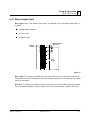
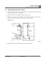
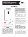
8. Raise the two side supports that will prevent a log from falling off the side of the mill when
loaded.
See Figure 2-3.
Pivot End Rail
Side Support
Bed Rail
Stop Block
SM0130
FIG. 2-3
2-4
HD92doc042701
Setup & Operation
Setup & Operation
Preparing The Sawmill For Operation
2.3
2
Preparing The Sawmill For Operation
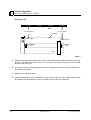
1. TUV Trailers only:
See Figure 2-4. Disassemble the perimeter fence. Remove the six locking pins and two
hold-down nuts. Unplug the tail light board from the auxiliary adapter. Remove all four
sections of the perimeter fence.
FIG. 2-4
Adjust the jockey wheel down by turning the crank clockwise until the wheel is planted
firmly on the ground. Set the brake by pushing the lever away from the hitch coupler. See
Trailer Option Manual for TUV trailer hitch operation.
Setup & Operation
HD92doc042701
2-5
Setup & Operation
2 Replacing The Blade
2.4
Replacing The Blade
WARNING! Always wear gloves and eye protection whenever handling bandsaw blades. Changing blades is safest
when done by one person! Keep all other persons away
from work area when changing blades. Do not change the
blade with the engine running.
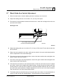
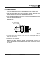
See Figure 2-5. Remove the blade housing cover(s) that are over the drive wheels. Turn
the tension handle to release the blade tension until the wheel is pulled in and the blade is
lying loose in the blade housing. Lift the blade out of the blade housing.
When installing a blade, make sure the teeth are pointing the correct direction. The teeth
should be pointing toward the operator side of the mill when you are looking at the blade
below the blade guides. Install the blade so it is lying around the wheels.
Position 1 1/4” wide blades on the wheels so the gullet is 1/8" (3.0 mm) out from the edge
of the wheel. Position 1 1/2” wide blades on the wheels so the gullet is 3/16” (4.5 mm) out
from the edge of the wheel.
Close the middle blade housing cover.
Next, turn the tension handle until the blade is tensioned correctly.
2-6
HD92doc042701
Setup & Operation
Setup & Operation
Tensioning The Blade
2.5
2
Tensioning The Blade
See Figure 2-5. Tension the blade by turning the hydraulic tensioning handle clockwise
until the tension gauge indicates the recommended tension.
Blade Tensioner
Gauge
Blade Tensioner
Handle
Cant Control
Handle
SM0043
FIG. 2-5
See Table 2-1. The recommended tensions for different blades is shown below.
Blade Type
Acceptable
Range
Ideal Tension
.035" x 7/8" x 1
1/4"
1800 - 2100
psi
2000 psi
.042" x 7/8" x 1
1/4"
2100 - 2400
psi
2300 psi
.045" x 7/8" x 1
1/2"
2100 - 2400
psi
2300 psi
TABLE 2-1
The tension gauge should be checked occasionally when adjusting the cant control or
while cutting. Ambient temperature changes will cause tension to change. Adjust the tension handle as necessary to maintain the recommended tension level.
CAUTION! The blade tension should be released when the
mill is not in use. Changes in temperature could cause
increased pressure in the tensioner and loss of fluid from
the gauge.
Setup & Operation
HD92doc042701
2-7
Setup & Operation
2 Tracking The Blade
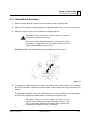
2.6
Tracking The Blade
Make sure the middle blade housing cover is closed and all persons are clear of the open
side of the saw head.
Start the engine (or motor). Pull lightly on the clutch handle, rotating the blade until the
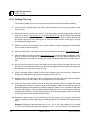
blade positions itself on the wheels.
See Figure 2-6. Position 1 1/4” wide blades so the gullet is 1/8" (3.0 mm) out from the
edge of the blade wheel (±1/32 [.75 mm]). Position 1 1/2” blades so the gullet is 3/16” (4.5
mm) out from the edge of the blade wheel (±1/32 [.75 mm]).
1/8" (3.0 m)
± 1/32" (0.75 mm)
1 1/4"
Blade
3/16" (4.5 mm)
± 1/32" (0.75 mm)
1 1/2"
Blade
SM0044C
FIG. 2-6
To adjust where the blade travels on the blade wheels, use the cant control handle shown
in Figure 2-5.
If the blade is too far out, back the blade onto the wheel by turning the cant control counterclockwise. If the blade is too far in, turn the cant control clockwise until the gullet of the
blade is is the correct distance from the front edge of the wheel.
2-8
HD92doc042701
Setup & Operation
Setup & Operation
Tracking The Blade
2
Retension the blade to the recommended tension to compensate for any adjustments you
have made in the cant control. Replace the covers.
DANGER! Never operate the sawmill without all guards
and covers in place and secured.
Be sure the blade housing and pulley covers are in place and secure. If applicable, use
the safety retainer pin and cable to fasten blade housing covers.
!
Setup & Operation
IMPORTANT! After aligning the blade on the wheels,
always double-check the blade guide spacing and location.
See Section 5 for more information.
HD92doc042701
2-9
Setup & Operation
2 Starting The Engine (or Motor)
2.7
Starting The Engine (or Motor)
See the appropriate manual supplied with your specific engine/motor configuration for
starting and operating instructions.
DANGER! Read the entire manual before operating your
Wood-Mizer sawmill.
DANGER! Never operate the sawmill without all guards
and covers in place and secured.
Be sure the blade housing and pulley covers are in place and secure before starting the
sawmill. If applicable, use the safety retainer pin and cable to fasten blade housing covers.
DANGER! Do not start the engine or motor when the
clutch/brake lever is in the engaged (down) position.
Always be sure the blade is disengaged and all persons are
away from the blade before starting the engine.
DANGER! Make sure the carriage fwd/rev switch is in the
neutral position before turning the key switch to the ON or
ACC position. This will prevent unintended carriage movement.
WARNING! Always wear eye, ear, and respiration protection when operating this equipment.
2-10
HD92doc042701
Setup & Operation
Setup & Operation
Hydraulic Control Operation
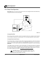
2.8
2
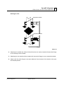
Hydraulic Control Operation
Revisions E7+
See Figure 2-7. Use the five control levers to do the following steps. This gets the mill
ready to load a log.
Turner
Rear
Toe Board
Front
Toe Board
Loader
Clamp
HD0027
FIG. 2-7
Setup & Operation
HD92doc042701
2-11
Setup & Operation
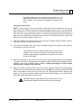
2 Hydraulic Control Operation
Revisions C7 - E6
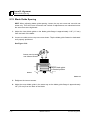
See Figure 2-8. Use the four control levers to do the following steps. This gets the mill
ready to load a log.
FIG. 2-8
CAUTION! Never operate the hydraulic controls without the
engine running. Power drainage from the battery will result.
Holding the hydraulic switches halfway up or down also will
cause excessive drainage from the battery.
DANGER! Keep all persons a safe distance away while
operating the sawmill. Leave loading arm halfway up while
log is on sawmill bed.
1. Lower the clamp lever to move the log clamp toward the loading side of the mill. Be sure
the clamp is in the down position so it will not get in the way of logs being loaded onto the
bed.
See Figure 2-9. The two-stage clamp can be raised or lowered by lowering the clamp
lever and moving the clamp all the way out. The clamp will engage the flip arm and flip the
clamp in either the up or down position.
A 3" clamp extension is located at the end of the clamp assembly or inside the battery box
of all hydraulic sawmills. The extension is used for small logs or boards needing a shorter
2-12
HD92doc042701
Setup & Operation
Setup & Operation
Hydraulic Control Operation
2
clamp. See Section 2.10
FIG. 2-9
2. Raise the log loader lever to extend the legs of the log loader out as far as they will go.
3. The chain securing the log loading arm to the log turner arm will be tight. Raise the log
turner lever to raise the turner arm until there is slack in the chain.
4. Unchain the loading arm from the turner arm.
5. Lower the turner lever to completely lower the turner arm. Notice that after the turner arm
is all the way down, the side support braces will begin to lower. Release the turner lever
after the turner arm is lowered, but before the side supports begin to lower. This stops the
log being loaded from damaging the turner and/or falling off the side of the sawmill.
6. When raising the turner lever, the side supports rise first. After reaching a fully vertical
position, the turner arm will engage and start to rise.
7. Manually lower the log loader so the legs rest on the ground.
CAUTION! Be careful when lowering the log loader. Do not
drop the loader onto the ground or perform any action
which might break the velocity fuse valves on the loader
cylinders. These valves control hydraulic flow and are necessary to prevent the loading arm from collasping during
use.
Setup & Operation
HD92doc042701
2-13
Setup & Operation
2 Hydraulic Control Operation
8. Lower the loader lever to lower the loading arm as far as it will go. Logs must be rolled
onto the loading arm one at a time for loading onto the bed of the mill.
9. The front and rear toe boards should be below bed level. Once a tapered log has been
loaded, the front or rear end of the log may be lifted to parallel the heart of the log to the
path of the blade.
Revisions E7+
The front toe board is raised by lifting the front toe board lever up. The rear toe board is
raised by lifting the rear toe board lever up. Once a flat has been made and the log is
ready to be turned, push the appropriate toe board lever down to lower either toe board
until it falls below the level of the bed.
Revisions C7 - E6
The front toe board is raised by lifting the toe board lever up. The rear toe board is raised
by pushing the lever down. Once a flat has been made and the log is ready to be turned,
the toe board release valve should be turned clockwise to lower either toe board until it
falls below the level of the bed.
CAUTION! Always be sure the toe boards are lowered
below bed level before turning or loading logs onto the bed.
Loading and turning logs or cants can cause permanent
damage to the toe boards if they are left in the up position.
2-14
HD92doc042701
Setup & Operation
Setup & Operation
Loading, Turning, And Clamping Logs
2.9
2
Loading, Turning, And Clamping Logs
CAUTION! Be sure the pivot end rails (if applicable), turning arm, clamp, and toe boards are out of the way before
loading a log onto the bed. Be sure logs are positioned on
the bed so that they will not damage the manual winch
when loaded. Also, be sure the cutting head is moved far
enough forward so the log does not hit it.
To Load Logs
1. Move a log up to the loading arm. Use the manual winch, cant hooks, or loading equipment to move the logs to the foot of the loading arms.
2. Roll the log onto the loader so that it is approximately centered with the sawmill bed. The
log turner will operate much easier if the log is centered on the sawmill bed.
3. Raise the loader lever to raise the log onto the sawmill bed. Simply let the loader rise until
the log rolls onto the mill bed.
4. Lower the loading arm. Leave the loading arm about halfway up while squaring the log.
This will stop the log from rolling off the side of the mill.
NOTE: Logs also may be loaded onto the mill with a tractor or other equipment specifically designed for that purpose.
5. Flip the clamp into the up position by lowering the clamp lever until the clamp contacts the
flip arm.
Setup & Operation
HD92doc042701
2-15
Setup & Operation
2 Loading, Turning, And Clamping Logs
To Turn Logs
1. Raise the turner lever to engage the log turner arm. Let the arm rise until it touches the
log and starts to turn it.
2. Spin the log against the side supports until it is turned the way you want it for the first cut.
If you want to turn the log more, do the following steps.
3. Engage the clamp by raising the clamp lever.
4. Clamp the log against the side supports.
5. Lower the turner lever to lower the turner arm below the log.
6. Raise the turner arm to get a new bite on the log.
7. Disengage the clamp.
8. The log can be turned now. Repeat steps 4 through 7 until the log is turned as desired.
To Clamp Logs
See Figure 2-10.
1. Raise the clamp lever and clamp the log against the side supports.
2. Lower the turner lever until the turner arm falls below the bed.
3. When the turner arm is lowered all the way, the side supports will begin to lower. Back the
clamp off slightly, and let the side supports come down until they are positioned below the
level of your first few cuts.
2-16
HD92doc042701
Setup & Operation
Setup & Operation
Loading, Turning, And Clamping Logs
2
To Level A Tapered Log
Use the toe board lever(s) to raise either end of a tapered log, if desired.
Revisions E7+
Raise the appropriate lever to raise the front or rear toe board until the heart of the log
measures the same distance from the bed rails at each end of the log.
Revisions C7 - E6
Raise the lever to raise the front toe board or lower the lever to raise the rear toe board
until the heart of the log measures the same distance from the bed rails at each end of the
log.
Setup & Operation
HD92doc042701
2-17
Setup & Operation
2 Clamp Extension
2.10 Clamp Extension
The clamp extension stored in the battery box or at the end of the clamp tube can be used
for clamping small cants or logs. The clamp extension is used with the hydraulic clamp in
its down position.
Clamp extensions made after 6/92 include a retaining pin which allows the clamp to be
stored on the clamp tube end plate.
See Figure 2-11. Remove the retaining pin and clamp extension from its storage position
at the end of the clamp assembly. Replace the pin in the storage hole.
Remove retaining pin
and clamp extension
from storage position
Slide clamp extension
over lip of
hydraulic clamp
HD0018
Return retaining
pin to storage
location
FIG. 2-11
The clamp should be removed from the clamp and returned to its storage position before
towing the mill.
2-18
HD92doc042701
Setup & Operation
Setup & Operation
Up/Down Operation
2
2.11 Up/Down Operation
1. Install a blade, if needed, and check for correct blade tension. See Section 2.5.
2. Set the cutting head to the desired height. (The blade height sight gauge and scale show
the height of the blade above the bed rails.)
See Figure 2-12. The up/down switch is located on the far right side of the control panel.
Push the switch up to raise the cutting head; push the switch down to lower the cutting
head. Hold the switch in position until the cutting head reaches the desired height, then
release.
FIG. 2-12
The up/down switch is designed to return to the neutral or "off" position when released. If
the switch remains engaged, manually move the switch to the neutral or "off" position.
Repair the up/down drum switch. See Section 4.2 Electrical Problems.
WARNING! Failure to move the up/down switch to the neutral or "off" position when released will result in failure to
stop saw head movement.
CAUTION! DO NOT try to force the carriage above the 35"
(88 cm) mark or below the 1" (2.54 cm) mark. Damage to
the chain may result.
Setup & Operation
HD92doc042701
2-19
Setup & Operation
2 Blade Guide Arm Operation
2.12 Blade Guide Arm Operation
1. Look down the length of the log to see its maximum width. The outer blade guide should
be adjusted to clear the widest section of the log by less than 1" (25.4 mm).
2. Use the blade guide toggle switch on the control panel to adjust the outer blade guide as
necessary. Push the switch to the left to move the arm in. Push the switch to the right to
move the arm out.
See Figure 2-13.
FIG. 2-13
3. Use the blade guide toggle switch to readjust the outer blade guide as you are cutting in
order to keep the guide within 1" (2.5 cm) of the log. Be sure to adjust the arm back out
before returning the carriage.
2-20
HD92doc042701
Setup & Operation
Setup & Operation
Clutch/Brake Operation
2
2.13 Clutch/Brake Operation
1. Clear any loose objects from the area of the blade, motor, and drive belt.
2. Make sure the clamp and side supports are adjusted below the level of your first few cuts.
3. Start the engine or motor as instructed in the engine manual.
DANGER! Never operate the sawmill without all guards
and covers in place and secured.
Be sure the blade housing and pulley covers are in place
and secure. If applicable, use the safety retainer pin and
cable to fasten blade housing covers.
See Figure 2-14. The clutch/brake lever is located next to the engine.
FIG. 2-14
4. To engage the blade, pull the lever down until it locks in the down position. This engages
the drive mechanism, releases the blade brake, and increases the engine speed to full
throttle.
To disengage the blade, raise the clutch/brake lever to the up position. This disengages
the drive belt, engages the blade brake, and returns the engine to idle.
CAUTION! Failing to stop the blade can cause it to be
pulled off by a wood sliver (while traveling in reverse). This
will ruin the blade. Stopping the blade when returning the
carriage also increases the life of the blade.
Setup & Operation
HD92doc042701
2-21
Setup & Operation
2 Power Feed Operation
2.14 Power Feed Operation
See Figure 2-15. The power feed system moves the carriage forward and backward by
using two switches on the control panel.
FIG. 2-15
Carriage Feed Rate
The carriage feed rate switch controls the speed at which the carriage travels forward.
Turn the switch clockwise to increase speed. Turn it counterclockwise to reduce speed.
Carriage Forward and Reverse
The carriage fwd/rev (forward/reverse) switch controls the direction in which the carriage
travels. Turn the fwd/rev switch upward to the CARRIAGE FWD position to move the carriage forward. Turn the switch down to the CARRIAGE REV position to move the carriage
backward.
The middle position (as shown) is the neutral position. The power feed switch is designed
to return to the neutral or "off" position when released from operating in the reverse position. If the switch remains engaged, manually move the switch to the neutral or "off" position. Repair up/down drum switch. See Section 4.2 Electrical Problems.
DANGER! Failure to move the up/down switch to the neutral or "off" position when released will result in failure to
stop saw head carriage movement.
2-22
HD92doc042701
Setup & Operation
Setup & Operation
Power Feed Operation
2
DANGER! Make sure the carriage fwd/rev switch is in the
neutral position before turning the key switch to the on or
ACC position. This prevents unintended carriage movement.
Using The Power Feed
HINT: To get a straight cut in the first part of the board, feed the blade into the log at a
slow speed. This stops the blade from flexing and dipping up or down. Turn the carriage
feed rate switch to a slow speed until the whole width of the blade has entered the cut.
Then use the carriage feed rate switch to increase the feed rate as desired. Maximum
feed rate varies with width and hardness of the wood. Over-feeding results in engine and
blade wear, and also produces a wavy cut.
1. Stop the carriage at the end of the cut by turning the carriage feed rate switch counterclockwise until the carriage stops moving.
2. Throw the clutch/brake lever UP to stop the blade and drop the engine to idle. Remove
the board from the top of the log.
CAUTION! Be sure to stop the blade when returning the
carriage. This will not only prevent the blade from being
pulled off and ruined by a wood sliver, but also will increase
the life of the blade.
3. Return the carriage to the front of the mill by turning the carriage fwd/rev switch DOWN.
The power feed motor will bypass the carriage feed rate switch and the carriage will automatically return at the fastest speed available. Always disengage the blade before
returning the carriage for the next cut.
4. Make sure that the blade does not catch on the end of the log. Raise the carriage slightly
to make sure the blade clears the log when returned. HINT: Try to stop the blade while the
heel of the blade is still on the log. Then bring the carriage back without adjusting the
blade up. This lets you keep the blade at the current height setting so you can make the
next blade height adjustment more quickly.
DANGER! Always keep away from the trailer axle to avoid
being caught between the axle and moving saw carriage.
Setup & Operation
HD92doc042701
2-23
Setup & Operation
2 Cutting The Log
2.15 Cutting The Log
The following steps guide you through normal operation of the Wood-Mizer sawmill.
1. Once the log is placed where you want it and clamped firmly turn the key switch to the
ACC position.
2. Determine where to make your first cut. The sight gauge and the blade height scale will
help you to do this (See Section 2.17 and See Section 2.18). Set the blade to the desired
height with the up/down switch. Make sure that the blade will clear all side supports and
the clamp. Adjust the outer blade guide to clear the widest section of the log by moving
the blade guide toggle switch.
3. Make sure all covers and guards are in place. Start the engine. Engage the clutch/brake
lever to start the blade spinning.
4. Start the water lube if necessary to prevent sap buildup on the blade. See Section 2.19.
5. Feed the blade into the log slowly (See Section 2.14). Once the blade completely enters
the log, increase the feed rate as desired. Always try to cut at the fastest speed you can
while keeping an accurate cut. Cutting too slowly will waste blade life and lower production!
6. As you get to the end of the log, slow down the feed rate. When the teeth exit the end of
the log, turn the feed rate all the way down and disengage the clutch/brake lever. Remove
the slab that you have just cut from the log.
7. Use the carriage fwd/rev switch to return the carriage to the front of the mill. Always disengage the blade before returning the carriage for the next cut.
8. Repeat until the first side of the log is cut as desired. Set aside the usable flitches (boards
with bark on one or both sides). You can edge them on the mill later.
9. Lower the toe boards, if they were used. Use the hydraulic levers to release the clamp
and engage the log turner. Turn the log 90 or 180 degrees. Make sure the flat on the log is
placed flat against side supports if turned 90 degrees. Make sure it is placed on bed rails
if turned 180 degrees. If the log was turned 90 degrees and you are using toe boards to
compensate for taper in the log, raise the front or rear toe board again on the second side
of the log until the heart is parallel with the bed.
10. Repeat the steps used to cut the first side of the log until the log is square. Cut boards
from the remaining cant by adjusting the blade height for the thickness of boards that you
want.
Example: Remember that the blade cuts a 1/16 - 1/8" (1.6-3.2 mm) wide kerf. If you want
1" (25.4 mm) thick boards, lower the carriage 1 1/16 - 1 1/8" (27-28.6 mm) for each board.
2-24
HD92doc042701
Setup & Operation
Setup & Operation
Edging
2
2.16 Edging
The following steps guide you through edging boards on the Wood-Mizer sawmill.
1. Raise the side supports to 1/2 the height of the flitches, or the boards that need to be
edged.
2. Stack the flitches on edge against the side supports.
3. Clamp the flitches against the side supports halfway up the flitch height. (Wider flitches
should be placed to the clamp side. When they are edged, flip them over to edge the second side without disturbing the other flitches or without having to pull them from the middle of the stack).
4. Adjust the blade height to edge a few of the widest boards.
5. Loosen the clamp and turn the edged boards over to edge the other side.
6. Repeat steps 2-4.
7. Loosen the clamp and remove the boards that have good clean edges on both sides.
Clamp the remaining flitches and repeat steps 2-5.
Setup & Operation
HD92doc042701
2-25
Setup & Operation
2 Blade Height Sight Gauge
2.17 Blade Height Sight Gauge
See Figure 2-16. The sight gauge is provided on the cutting head carriage to help you
decide where to make the first cuts on a log.
SM0047
Sight gauge eye-level
with bottom of blade
FIG. 2-16
Move the carriage forward until the blade is close to the end of the log.
Position yourself so that your eyes are level with the bottom of the sight gauge spring.
With one eye closed, move your head up or down until the bottom of the sight gauge is
lined up with the bottom of the blade.
Sight down the length of the log. You should be able to see where the blade will pass
through the log down its entire length. Raise or lower the cutting head until you get the
blade height you want.
HINT: After judging by eye where you want to make your first slab cut, check the scale.
Move the up/down crank to fine-tune the blade height to an even measurement on the
blade height scale.
Example: Adjust the blade up to 15" rather than cut at 14 13/16". This will make adjustments for the next cuts easier to figure on the scale.
2-26
HD92doc042701
Setup & Operation
Setup & Operation
Blade Height Scale
2
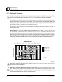
2.18 Blade Height Scale
See Figure 2-17. The blade height scale is attached to the carriage head frame. It
includes:
a blade height indicator
an inch scale
a quarter scale
Blade Height
Indicator
6
Quarter
Scale
5
14
4
8
15
6 5
4
16
4
8
5
17
6
4
18
5
8
Inch
Scale
4
6
3H0007
FIG. 2-17
Rev C7-D2: The indicator is attached to the frame and moves up and down with the carriage head. A retrofit is available so that the indicator remains at eye level and the scales
move up and down.
Rev D3+: The scales are attached to the frame and move up and down with the carriage
head. The blade indicator, used to read the inch and quarter scales, remains stationary.
Setup & Operation
HD92doc042701
2-27
Setup & Operation
2 Blade Height Scale
The Inch Scale
The horizontal red line on the blade height indicator shows how many inches the bottom
of the blade is above the bed of the mill. If you know the height of your blade at each cut,
you can determine the thickness of lumber you are sawing.
Example: You want to cut 1" (25 mm) random width boards from a log. Use the sight
gauge to position the blade for the first cut. Move the carriage to an even measurement
on the inch scale. Make a trim cut. Return the carriage for the second cut and lower it 1
1/8" (29 mm) below the original measurement. (The extra 1/8" (3 mm) allows for saw kerf
and shrinkage of the lumber.)
Rev. F2+: The scale is shaded. White identifies areas where the blade could encounter a
side support or the clamp. Yellow identifies areas where the blade could encounter a side
support only.
2-28
HD92doc042701
Setup & Operation
Setup & Operation
Blade Height Scale
2
The Quarter Scale
See Table 2-2. Two quarter scales are provided with four sets of marks. Each set represents a specific lumber thickness. Saw kerf and shrinkage allowance are included, but
actual board thickness will vary slightly depending on blade thickness and tooth set.
To choose which scale to use, determine what finished thickness you want to end up with.
The Grade Hardwood Quarter Scale provides thicker finished boards usually required by
commercial buyers. The Standard Quarter Scale allows for kerf and shrinkage of finished
boards suitable for most custom applications. Always check with your customer before
you saw to determine what actual finished thickness is required.
Standard Quarter Scale
Scale
Actual Board Thickness
4/4
1" (25 mm)
5/4
1 1/4" (32 mm)
6/4
1 5/8" (41 mm)
8/4
2 1/8" (54 mm)
Grade Hardwood Quarter Scale1
Scale
Actual Board Thickness
4/4
1 1/8" (29 mm)
5/4
1 3/8" (35 mm)
6/4
1 5/8" (41 mm)
8/4
2 1/8" (54 mm)
TABLE 2-2
1 Supplied
after 5/95.
To use the quarter scale, look at the blade height indicator. Line up the horizontal red line
on the indicator with the nearest mark on the scale you want to use. Make a trim cut.
When you return the carriage for a second cut, lower the carriage to the next mark on the
scale. This mark shows where the blade should be positioned to cut a certain thickness of
lumber, without having to measure on the inch scale.
Example: You want to cut 1" (25 mm) (4/4) random width boards from a log. Use the sight
gauge to position the blade for the first cut. Adjust the quarter scale so a 4/4 mark is
aligned with the red line on the indicator. Make a trim cut. Return the carriage for the second cut. Now, instead of having to measure down 1 1/8" (29 mm) on the inch scale, you
can simply lower the blade so the indicator is aligned with the next 4/4 mark on the quarter scale. Turn the log 90 degrees and repeat.
Setup & Operation
HD92doc042701
2-29
Setup & Operation
2 Water Lube Operation
2.19 Water Lube Operation
See Figure 2-18. The Water Lube System keeps the blade clean. Water flows from a
5-gallon (18.9 liter) bottle through a hose to the blade guide where the blade enters the
log. A valve in the bottle cap controls the amount of water flow.
FIG. 2-18
Not all types of wood require the use of the Water Lube System. When it is needed, use
just enough water to keep the blade clean. This saves water, and lowers the risk of staining the boards with water. Usual flow will be 1-2 gallons (3.8-7.6 liters) per hour. A squirt
of liquid dishwashing detergent in the water bottle will help clean the blade when cutting
wood with a high sap content.
WARNING! Never use flammable fuels or liquids instead of
water with this accessory. If these type of liquids are necessary to clean the blade, remove it and clean with a rag.
Before removing the blade, engage the clutch/brake lever. Let the blade spin with water
running on it for about 15 seconds. This will clean the blade of sap buildup. Wipe the
blade dry with a rag before storing or sharpening.
If you are sawing in freezing temperatures, remove the water lube bottle from the sawmill
when done sawing and store it in a warm place. Blow any remaining water from the water
lube hose.
2-30
HD92doc042701
Setup & Operation
Setup & Operation
Preparing The Sawmill For Towing
2
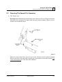
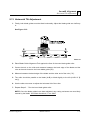
2.20 Preparing The Sawmill For Towing
The Wood-Mizer trailer package makes transporting your sawmill easy and convenient.
To get your sawmill ready for towing, follow these instructions.
1. Move the saw carriage to the front end of the sawmill. Raise the rear outriggers.
2. Use the hydraulic controls to move the log clamp all the way toward the loading side of
the mill.
CAUTION! Failure to fully extend the log clamp before towing can result in damage to the clamping assembly during
towing.
3. Use the hydraulic controls to raise the log turner and loader as high as they will go. Manually lift the loader and hook the loader chain to the elbow of the turner. Use the hydraulic
turner lever to lower the turner until the chain is tight. Push the loader lever down to bring
the loader arm channels up to the loader.
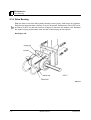
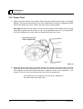
4. Move the carriage forward to the travel position over the rear bed rail.
5. Position the holes in the saw head over the travel rest pin.
6. Lower the saw head until it is seated firmly on the rest pin.
See Figure 2-19.
FIG. 2-19
Setup & Operation
HD92doc042701
2-31
Setup & Operation
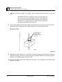
2 Preparing The Sawmill For Towing
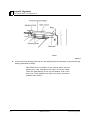
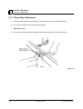
7. Continue lowering the head 3/4" (19mm). until it contacts the stop blocks on the mast
rails.
CAUTION! Failure to properly secure the saw head can
result in severe machine damage. Lower the saw head onto
the rest pin until it contacts the rest pin collar, then lower the
saw head 3/4" (19mm) further to insure that the saw head
cannot be dislocated from the rest pin.
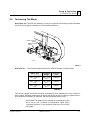
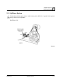
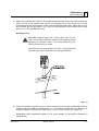
8. If necessary, adjust the two stops located at the bottom of the mast so the saw head contacts them after it is lowered 3/4" (19mm) past where it contacts the rest pin.
See Figure 2-20.
Loosen jam nut
and turn bolt
to raise or lower
stop bolt
SM0111
FIG. 2-20
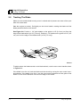
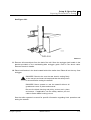
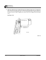
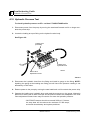
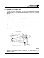
9. Engage the clutch/brake lever. This keeps the drive belt tight and the motor from bouncing while traveling. Be sure to disengage the clutch/brake handle after reaching the destination to avoid deformation of the drive belt.
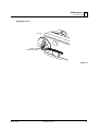
10. Hook the carriage safety chain located at the bottom of the carriage to the bracket at the
bottom of the mast.
2-32
HD92doc042701
Setup & Operation
Setup & Operation
Preparing The Sawmill For Towing
2
See Figure 2-21.
FIG. 2-21
11. Remove all loose objects from the bed of the mill. Store the outrigger jack handle in the
bracket provided on the rear/loading-side outrigger guide. Reel in the winch cable.
Remove the winch handle.
12. Place both fenders in the slots located behind the trailer tires. Raise all but the very front
outrigger.
DANGER! Check to be sure the saw head is resting firmly
on the rest pin and mast rail stops and that the safety chain
is secured before towing the sawmill.
DANGER! Never operate or tow the sawmill without all
guards and covers in place and secured.
Be sure the blade housing and pulley covers are in place
and secure. If applicable, use the safety retainer pin and
cable to fasten blade housing covers.
See the trailer operator’s manual for specific information regarding hitch operation and
towing the sawmill.
Setup & Operation
HD92doc042701
2-33
Maintenance
Wear Life
3
SECTION 3 MAINTENANCE
This section lists the maintenance procedures that need to be performed.
The Short Interval Maintenance Schedule lists procedures that need to be performed
every 4, 8 or 25 hours.The Maintenance Log lists procedures that need to be performed
every 50, 100, 200, 300, 500, or 1000 hours. Keep track of machine maintenance by filling in the machine hours and the date you perform each procedure.
0
3.1
This symbol identifies the interval (hours of operation) at which each maintenance procedure should be performed.
Wear Life
See Table 3-1. This chart lists estimated life expectancy of common replacement parts if
proper maintenance and operation procedures are followed. Due to the many variables
which exist during sawmill operation, actual part life may vary significantly. This information is provided so that you may plan ahead in ordering replacement parts.
Part Description
Estimated
Life
Up/Down Motor Brushes
375 hours
B57 Blade Wheel Belts
500 hours
Up/Down Motor
750 hours
Hydraulic Pump Solenoid
750 hours
Power Feed Motor
Brushes
750 hours
Up/Down Drum Switch
1000 hours
Blade Guide Rollers
1000 hours
Hydraulic Pump Motor
Brushes
1000 hours
Power Feed Drum Switch
1200 hours
Drive Belt
1250 hours
Power Feed Motor
1500 hours
Power Feed Belt
2000 hours
Up/Down Belt
2000 hours
TABLE 3-1
Maintenance
HD92doc042701
3-1
Maintenance
3 Blade Guides
3.2
Blade Guides
See Figure 3-1.
1. Lubricate the blade guide rollers every four hours of operation. Use one squeeze of a
NLGI No. 2 grade lithium grease from a grease gun to lubricate the bearings and remove
4
any sawdust.
Grease blade
guide rollers (2)
SM0052B
FIG. 3-1
CAUTION! Do not over-grease. Over-greasing will push the
seals out of the blade guide bearings.
2. Check the rollers for performance and wear every blade change. Make sure the rollers
are clean and spinning freely. If not, rebuild them. Replace any rollers which have worn
smooth or have become cone shaped. See The LT30HD/40HD Parts manual for blade
guide rebuild kits and complete roller assemblies.
3. The blade guide set screws on sawmills built after 9/93 are stainless steel which prevent
corrosion from making the screws difficult to adjust. Screws on older sawmills may be
replaced with the stainless steel screw.
3-2
HD92doc042701
Maintenance
Maintenance
Hydraulic Log Loader
3.3
8
3
Hydraulic Log Loader
Remove all sawdust and debris from around the velocity fuse valves every 8 hours of
operation. The valves are located at the bottom of the log loader cylinders.
Maintenance
HD92doc042701
3-3
Maintenance
3 Blade Housing
3.4
Blade Housing
1. Remove the excess sawdust from the blade wheel housings and sawdust chute every
blade change.
See Figure 3-2.
2. Make sure the blade screw (or cam bearing on machines before 11/91) in the top center
of the C-frame is 1/16" (1.5 mm) below the bottom of the blade. If not, loosen the nut and
adjust the screw as necessary. Check the screw every blade change. Failing to maintain
this adjustment will lead to early blade breakage.
1/16“ (1.6 mm)
SM0054
FIG. 3-2
3-4
HD92doc042701
Maintenance
Maintenance
Carriage Track, Wiper & Scrapers
3.5
3
Carriage Track, Wiper & Scrapers
See Figure 3-3.
1. Clean the upper and lower track rails to remove any sawdust and sap buildup every eight
hours of operation. Lubricate the lower track rail by wiping it with Dexron III ATF.
8
NOTE: If the top rail is not factory painted, apply a rust inhibitor such as Sherwin-Williams
P.D.R.P #710 when the sawmill is not in use. Use a clean, dry cloth and a light lubricant
such as WD-40 to remove the protection coat before operating the sawmill.
FIG. 3-3
2. Remove sawdust from the upper cam housings. Loosen the thumb screws on the upper
cam housing covers and open. Brush any sawdust buildup from the housings.
8
3. Check the track scrapers as needed. Make sure the scrapers fit firmly against the rail. If a
track scraper needs to be adjusted, loosen the thumb screw, push the scraper downward
until it fits firmly against the rail, and retighten the thumb screw.
4. Clean and lubricate the track wiper every twenty-five hours of operation. Unbolt the wiper,
remove it from the sawmill, and remove any sawdust buildup. Soak the felt wiper with
25
Dexron III transmission fluid, 10W30 motor oil or 3-in-1 turbine oil. Replace the wiper.
CAUTION! Reinstall the wiper so that it lightly touches the
track rail. If the wiper presses too firmly against the rail, it
can cause the power feed to bind.
Maintenance
HD92doc042701
3-5
Maintenance
3 Track Rollers
3.6
Track Rollers
See Figure 3-4.
1. Lubricate the greasable track roller bearings every fifty hours of operation. Use a NLGI
No. 2 grade lithium grease.
50
FIG. 3-4
3-6
HD92doc042701
Maintenance
Maintenance
Vertical Mast Rails
3.7
50
3
Vertical Mast Rails
Clean and lubricate the vertical mast rails every 50 hours of operation. Clean with solvent
and remove any rust with a light-grade sand paper or emery cloth. Lubricate the mast with
motor oil or automatic transmission fluid (ATF).
CAUTION! Never use grease on the mast rails as it will collect sawdust.
Maintenance
HD92doc042701
3-7
Maintenance
3 Drum Switches
3.8
50
Drum Switches
Lubricate the up/down and power feed drum switch contacts inside the control panel
every fifty hours of operation. Use only contact grease supplied by Wood-Mizer. Remove
the control panel cover. Use a cotton swab to apply grease to the switch contact ends.
WARNING! Drum switch grease contains Petroleum Hydrocarbon Lubricant. Eye and skin irritant. If introduced into
eyes, flush with water for at least 15 minutes. If film or irritation persists, seek medical attention. Wash skin with soap
and water. If ingested, do not induce vomiting - contact a
physician. KEEP OUT OF THE REACH OF CHILDREN.
3-8
HD92doc042701
Maintenance
Maintenance
Miscellaneous Lubrication
3.9
3
Miscellaneous Lubrication
1. Apply a thin film of a NLGI No. 2 grade lithium grease to the blade guide arm every fifty
hours of operation to help prevent it from rusting.
50
2. Grease the clamp mechanism, loading arm, and side supports with a NLGI No. 2 grade
lithium grease every fifty hours of operation.
50
3. Oil all chains with Dexron III ATF every fifty hours of operation.
50
CAUTION! Do not use chain lube. It causes sawdust
buildup in chain links.
Maintenance
HD92doc042701
3-9
Maintenance
3 Blade Tensioner
3.10 Blade Tensioner
1. Lubricate the chrome rods of the tensioner system with a heavy duty teflon spray lubricant, such as Gunk L508, every fifty hours of operation.
50
2. Lubricate the tensioner screw handle with a NLGI No. 2 grade lithium grease as needed.
See Figure 3-5.
FIG. 3-5
3-10
HD92doc042701
Maintenance
Maintenance
Blade Wheel Belts
3
3.11 Blade Wheel Belts
1. Rotate the blade wheel belts and check them for wear. Rotating the belts every 50 hours
will give you longer belt life. Replace belts as necessary. Use only B57 belts manufac50
tured by Goodyear or Browning.
2. Periodically check all belts for wear. Replace any damaged or worn belts as needed.
Maintenance
HD92doc042701
3-11
Maintenance
3 Brake Strap Adjustment
3.12 Brake Strap Adjustment
200
Hydraulic Sawmills Revisions F2+: Check the brake strap for wear every 200 hours of
operation. Replace if damaged or worn.
Also check and adjust the brake strap if the blade does not stop quickly, unusual sounds
occur when the brake is applied, or a sudden change is noticed in the clutch handle position when the clutch is disengaged. To access the brake strap, remove the belt cover
located underneath the engine. Engage the clutch/brake lever. Loosen the two brake
strap clamping bolts and slide the lower brake strap clamping plate and metal-backed
brake strap forward until snug. Retighten the bolts. Replace the belt cover.
Metal-backed
brake strap
Brake strap
clamping bolts (2)
Lower
clamping plate
SM0056B
FIG. 3-5
50
3-12
Hydraulic Sawmills Revisions F1 and Prior: Check the brake strap after the first 20 hours,
and every 50 hours thereafter. If the blade does not stop quickly, the brake strap needs
adjusting. To access the brake strap, remove the two belt covers located underneath the
engine. Engage the clutch/brake lever. Loosen the two brake strap clamping bolts and
pull the brake strap about 1/2" (12.7 mm) through the clamping plates. Retighten the
bolts. Replace the belt guards.
HD92doc042701
Maintenance
Maintenance
Brake Strap Adjustment
3
See Figure 3-6.
Metal-backed
brake strap
Brake strap
clamping bolts (2)
Lower
clamping plate
SM0056B
FIG. 3-6
Maintenance
HD92doc042701
3-13
Maintenance
3 Hydraulic System
3.13 Hydraulic System
1. Check the hydraulic fluid level every fifty hours of operation. Add fluid as necessary. The
level in the hydraulic pump should be 4 1/2" (114 mm) with all cylinders collapsed.
50
If humidity is a problem or the mill is used outside in humid weather, drain and replace two
quarts (.95 liters) of fluid every six months. This will drain any accumulated water and
help prevent pump failure due to water ingestion. It also will prevent excessive fluid wear
and allow the fluid to maintain its hot end performance.
If humidity is not a problem, drain and replace one gallon (3.8 liters) of fluid every year to
prevent fluid wear.
See Figure 3-7. If you are operating in temperatures -20° to 100° F (-29° to 38° C), use
an all-weather hydraulic fluid such as Exxon Univis J26. For alternate fluids and/or other
temperature ranges, refer to the chart below. Operating above the recommended temperature range of a fluid could result in excessive pump wear. Operating below the recommended temperature range could result in reduced hydraulic cylinder speed. To change
fluid types, replace one gallon of the current fluid with one gallon of the alternate fluid.
TEMPERATURE
F -30° -20° -10° 0° 10° 20° 30° 40° 50° 60° 70° 80° 90° 100° 110° 120°
C -35° -29° -23° -18° -12° -7° -1°
5°
10° 16° 21° 27° 32° 38° 44° 49°
HYDRAULIC FLUID
Level A Fluid
Level B Fluid
Level C Fluid
HD0049B
FIG. 3-7
2. Hydraulic Sawmills Revisions E7+ Only: Replace the hydraulic system cartridge filter
every 500 hours of operation.
500
3. Hydraulic Sawmills purchased before 12/93 Only: Service the hydraulic drive motor
(D.C. Motor) every 500 hours of operation. Refer to the Electrical Problems section of the
500
Monarch manual, page 7, section 2, steps A-H. Also make sure the slots between the
commutator segments are clear of foreign material.
3-14
HD92doc042701
Maintenance
Maintenance
Hydraulic System
3
To check for excessive end play, as listed in step H, perform the following:
Remove the rear head assembly.
Position (push) the armature shaft to assure that it's drive tab is fully engaged with
the pump shaft slot.
Position (push) the stator frame so it is tight against the pump.
Lay a 6" (15 cm) straightedge across the shaft's exposed bearing journal so it is in
contact with the end of the stator's outer wrap.
Measure the gap between the straightedge and the fiber thrust washers located
against the end of the commutator.
Add fiber washers as needed to give a .02 to .05 inch (.51 to 1.27 mm) gap.
Make sure the washer which contacts the end of the commutator is made of steel.
Assemble the rear head assembly to the motor.
4. Periodically check all hydraulic lines and fitting as needed. Replace as necessary.
Maintenance
HD92doc042701
3-15
Maintenance
3 Drive Bearing
3.14 Drive Bearing
1000
Refill the fluid in the drive-side cylinder bearing housing every 1000 hours of operation.
Remove the top and bottom oil plugs. Pour an Automatic Transmission Fluid (ATF) such
as Dexron III ATF into the top hole until it begins to flow from the bottom hole. Reinstall
the square oil plug to the bottom hole and the vented oil plug to the top hole.
See Figure 3-8.
FIG. 3-8
3-16
HD92doc042701
Maintenance
Maintenance
Up/Down System
3
3.15 Up/Down System
1. Grease the up/down gear reducer shaft bearing with a NLGI No. 2 grade lithium grease
every 1000 hours of operation.
1000
See Figure 3-9.
FIG. 3-9
Maintenance
HD92doc042701
3-17
Maintenance
3 Up/Down System
2. Adjust the up/down belt as needed. Remove the up/down housing cover. To tighten the
belt, loosen the two motor mount nuts. Adjust the bolt underneath the motor upward so
there is 3/8" (9.5 mm) deflection with a 7 lb. (3.2 Kg) deflection force. Tighten the jam nut
to secure the bolt in place. Retighten the motor mount nuts. Replace the drive pulley
cover.
See Figure 3-10.
FIG. 3-10
3-18
HD92doc042701
Maintenance
Maintenance
Up/Down System
3
3. Adjust the up/down chain tension as needed. Measure chain tension with the head all the
way to the top of the vertical mast. Secure the carriage with a chain at the top. Find the
chain adjusting bolt at the bottom of the mast, behind the battery box. Adjust the nuts on
the bolt until you can get about 1 1/2" (3.8 cm) total deflection in the center of the chain
with a 5 lb. (2.3 Kg) deflection force.
See Figure 3-11.
DANGER! Always secure the cutting head with a 5/16”
chain with at least 1900 lbs. working load capacity before
adjusting the up/down chain. The cutting head may fall,
causing severe injury or death.
CAUTION! Do not over-tension the chain. Over-tensioning
the chain may lead to early failure of the gear reducer.
FIG. 3-11
4. Check the up/down gearbox oil level. Add a synthetic gear oil such as Mobil SHC 634 as
needed. Drain and refill the gearbox with 14 - 16 ounces of oil after the first 100 hours of
sawmill operation. Repeat every 5000 hours or once a year, whichever comes first.
Wood-Mizer offers replacement gear oil in 8 ounce bottles (2 required for complete oil
replacement).
Maintenance
HD92doc042701
3-19
Maintenance
3 Power Feed
3.16 Power Feed
1. Adjust the power feed belt as needed. When the power feed belt gets loose, it will begin
slipping. This causes the carriage to not move forward when cutting. To retighten the belt,
remove the feed motor cover. Loosen the three motor mounting bolts.
See Figure 3-12. Pivot the motor so that the motor pulley moves away from the large
feed pulley. Tighten the belt so there is 1/8" (3 mm) deflection with a 7 lb. (3.2 Kg) deflection force. Retighten the motor bolts and replace the feed motor cover.
FIG. 3-12
2. Adjust the power feed chain as needed. Measure the power feed chain tension with the
saw head all the way toward the front of the mill. Use the two lock nuts at the rear of the
mill to tighten or loosen the power feed chain. Adjust the chain until it measures 7 to 8
inches (17.8 to 20.3 cm) from the top of the top rail at its lowest point.
CAUTION! Do not overtighten the feed chain. Damage to
the power feed motor may result.
3-20
HD92doc042701
Maintenance
Maintenance
Power Feed
3
See Figure 3-13.
3H0018B
Feed Chain
Adjustment Nuts
FIG. 3-13
Maintenance
HD92doc042701
3-21
Maintenance
3 Miscellaneous Maintenance
3.17 Miscellaneous Maintenance
1. Check the mill alignment every setup. See Section 5, Alignment.
2. Make sure all safety warning decals are readable. Remove sawdust and dirt. Replace any
damaged or unreadable decals immediately. Order decals from your Customer Service
Representative.
WARNING! Keep all safety warning decals clean and visible. If decal becomes worn or damaged, replace immediately.
3. Check all battery and fuse box connections are tight and free of corrosion. In 7/93, the
fuse block assembly was upgraded to prevent connections from coming loose and overheating. The fuse block can be retrofitted to LT30HD/40HD rev D3-E2.
3-22
HD92doc042701
Maintenance
SEE SECTION 3.4
SEE SECTION 3.4
Remove Excess Sawdust From Blade Wheel Housings And Sawdust Chute
Check Blade Screw (or cam bearing)
f:\manuals\forms\63592
Clean And Lubricate Upper Track Wiper
HD92doc040301
SEE SECTION 3.3
Clean Sawdust From Hydraulic Loader Velocity Fuse Valves
SEE SECTION 3.5
SEE SECTION 3.5
Remove Sawdust From Upper Cam Housings
EVERY 25 HOURS
SEE SECTION 3.5
Clean And Lubricate Track
EVERY 8 HOURS
SEE SECTION 3.2
SEE SECTION 3.2
MANUAL
REFERENCE
Check Blade Guide Roller Performance
EVERY BLADE CHANGE
Lubricate Blade Guide Rollers
EVERY 4 HOURS
PROCEDURE
LT30HD/40HD Short Interval Maintenance Schedule
See Section 3.6
See Section 3.8
See Section 3.9
See Section 3.15
See Section 3.16
See Section 3.15
See Section 3.16
See Section 3.12
See Section 3.11
See Section 3.15
See Section 3.16
See Section 3.15
See Section 3.10
See Section 3.13
See Section 3.13
See Section 3.13
See Section 3.13
See Section 3.14
See Section 3.15
Lubricate drum switches
Grease pivot points and bearings/Oil chains
Check belt tensions
Check brake strap tension
Rotate drive/idle blade wheel belts/Check all belts for
wear
Check feed & up/down chain tensions
Check up/down gear box fluid level
Lubricate blade tensioner handle and rods
Inspect hydraulic lines & fittings
Check hydraulic fluid level
Replace hydraulic system filter (Rev E7+)
Service Hydraulic Drive Motor (Rev C7 - E6)
Replace cylinder drive bearing fluid
Grease up/down shaft bearing
f:\manuals\forms\624
See Section 3.7
Grease track rollers (If greasable rollers)
MANUAL
REFERENCE
Clean & lube mast rails
PROCEDURE
50 HRS
150 HRS
HD92doc042701
100 HRS
200 HRS
25O HRS
300 HRS
350 HRS
400 HRS
450 HRS
TOTAL HOURS OF OPERATION
FILL IN THE DATE AND THE MACHINE HOURS AS YOU PERFORM EACH PROCEDURE.
A SHADED BOX INDICATES MAINTENANCE IS NOT NEEDED AT THIS TIME.
WOOD-MIZER LT30HD/LT40HD MAINTENANCE LOG
500 HRS
See Section 3.6
See Section 3.8
See Section 3.9
See Section 3.15
See Section 3.16
See Section 3.15
See Section 3.16
See Section 3.12
See Section 3.11
See Section 3.15
See Section 3.16
See Section 3.15
See Section 3.10
See Section 3.13
See Section 3.13
See Section 3.13
See Section 3.13
See Section 3.14
See Section 3.15
Lubricate drum switches
Grease pivot points and bearings/Oil chains
Check belt tensions
Check brake strap tension
Rotate drive/idle blade wheel belts/Check all belts for
wear
Check feed & up/down chain tensions
Check up/down gear box fluid level
Lubricate blade tensioner handle and rods
Inspect hydraulic lines & fittings
Check hydraulic fluid level
Replace hydraulic system filter (Rev E7+)
Service Hydraulic Drive Motor (Rev C7 - E6)
Replace cylinder drive bearing fluid
Grease up/down shaft bearing
f:\manuals\forms\624
See Section 3.7
Grease track rollers (If greasable rollers)
MANUAL
REFERENCE
Clean & lube mast rails
PROCEDURE
600 HRS
650 HRS
HD92doc042701
550 HRS
700 HRS
75O HRS
800 HRS
850 HRS
900 HRS
950 HRS
TOTAL HOURS OF OPERATION
FILL IN THE DATE AND THE MACHINE HOURS AS YOU PERFORM EACH PROCEDURE.
A SHADED BOX INDICATES MAINTENANCE IS NOT NEEDED AT THIS TIME.
WOOD-MIZER LT30HD/LT40HD MAINTENANCE LOG
1000 HRS
See Section 3.6
See Section 3.8
See Section 3.9
See Section 3.15
See Section 3.16
See Section 3.15
See Section 3.16
See Section 3.12
See Section 3.11
See Section 3.15
See Section 3.16
See Section 3.15
See Section 3.10
See Section 3.13
See Section 3.13
See Section 3.13
See Section 3.13
See Section 3.14
See Section 3.15
Lubricate drum switches
Grease pivot points and bearings/Oil chains
Check belt tensions
Check brake strap tension
Rotate drive/idle blade wheel belts/Check all belts for
wear
Check feed & up/down chain tensions
Check up/down gear box fluid level
Lubricate blade tensioner handle and rods
Inspect hydraulic lines & fittings
Check hydraulic fluid level
Replace hydraulic system filter (Rev E7+)
Service Hydraulic Drive Motor (Rev C7 - E6)
Replace cylinder drive bearing fluid
Grease up/down shaft bearing
f:\manuals\forms\624
See Section 3.7
MANUAL
REFERENCE
Grease track rollers (If greasable rollers)
PROCEDURE
1100 HRS
1150 HRS
HD92doc042701
1050 HRS
1200 HRS
125O HRS
1300 HRS
1350 HRS
1400 HRS
1450 HRS
TOTAL HOURS OF OPERATION
FILL IN THE DATE AND THE MACHINE HOURS AS YOU PERFORM EACH PROCEDURE.
A SHADED BOX INDICATES MAINTENANCE IS NOT NEEDED AT THIS TIME.
WOOD-MIZER LT30HD/LT40HD MAINTENANCE LOG
Clean & lube mast rails
]
1500 HRS
See Section 3.6
See Section 3.8
See Section 3.9
See Section 3.15
See Section 3.16
See Section 3.15
See Section 3.16
See Section 3.12
See Section 3.11
See Section 3.15
See Section 3.16
See Section 3.15
See Section 3.10
See Section 3.13
See Section 3.13
See Section 3.13
See Section 3.13
See Section 3.14
See Section 3.15
Lubricate drum switches
Grease pivot points and bearings/Oil chains
Check belt tensions
Check brake strap tension
Rotate drive/idle blade wheel belts/Check all belts for
wear
Check feed & up/down chain tensions
Check up/down gear box fluid level
Lubricate blade tensioner handle and rods
Inspect hydraulic lines & fittings
Check hydraulic fluid level
Replace hydraulic system filter (Rev E7+)
Service Hydraulic Drive Motor (Rev C7 - E6)
Replace cylinder drive bearing fluid
Grease up/down shaft bearing
f:\manuals\forms\624
See Section 3.7
Grease track rollers (If greasable rollers)
MANUAL
REFERENCE
Clean & lube mast rails
PROCEDURE
1600 HRS
1650 HRS
HD92doc042701
1550 HRS
1700 HRS
175O HRS
1800 HRS
1850 HRS
1900 HRS
1950 HRS
TOTAL HOURS OF OPERATION
FILL IN THE DATE AND THE MACHINE HOURS AS YOU PERFORM EACH PROCEDURE.
A SHADED BOX INDICATES MAINTENANCE IS NOT NEEDED AT THIS TIME.
WOOD-MIZER LT30HD/LT40HD MAINTENANCE LOG
2000 HRS
See Section 3.6
See Section 3.8
See Section 3.9
See Section 3.15
See Section 3.16
See Section 3.15
See Section 3.16
See Section 3.12
See Section 3.11
See Section 3.15
See Section 3.16
See Section 3.15
See Section 3.10
See Section 3.13
See Section 3.13
See Section 3.13
See Section 3.13
See Section 3.14
See Section 3.15
Lubricate drum switches
Grease pivot points and bearings/Oil chains
Check belt tensions
Check brake strap tension
Rotate drive/idle blade wheel belts/Check all belts for
wear
Check feed & up/down chain tensions
Check up/down gear box fluid level
Lubricate blade tensioner handle and rods
Inspect hydraulic lines & fittings
Check hydraulic fluid level
Replace hydraulic system filter (Rev E7+)
Service Hydraulic Drive Motor (Rev C7 - E6)
Replace cylinder drive bearing fluid
Grease up/down shaft bearing
f:\manuals\forms\624
See Section 3.7
Grease track rollers (If greasable rollers)
MANUAL
REFERENCE
Clean & lube mast rails
PROCEDURE
2100 HRS
2150 HRS
HD92doc042701
2050 HRS
2200 HRS
225O HRS
2300 HRS
2350 HRS
2400 HRS
2450 HRS
TOTAL HOURS OF OPERATION
FILL IN THE DATE AND THE MACHINE HOURS AS YOU PERFORM EACH PROCEDURE.
A SHADED BOX INDICATES MAINTENANCE IS NOT NEEDED AT THIS TIME.
WOOD-MIZER LT30HD/LT40HD MAINTENANCE LOG
2500 HRS
See Section 3.6
See Section 3.8
See Section 3.9
See Section 3.15
See Section 3.16
See Section 3.15
See Section 3.16
See Section 3.12
See Section 3.11
See Section 3.15
See Section 3.16
See Section 3.15
See Section 3.10
See Section 3.13
See Section 3.13
See Section 3.13
See Section 3.13
See Section 3.14
See Section 3.15
Lubricate drum switches
Grease pivot points and bearings/Oil chains
Check belt tensions
Check brake strap tension
Rotate drive/idle blade wheel belts/Check all belts for
wear
Check feed & up/down chain tensions
Check up/down gear box fluid level
Lubricate blade tensioner handle and rods
Inspect hydraulic lines & fittings
Check hydraulic fluid level
Replace hydraulic system filter (Rev E7+)
Service Hydraulic Drive Motor (Rev C7 - E6)
Replace cylinder drive bearing fluid
Grease up/down shaft bearing
f:\manuals\forms\624
See Section 3.7
Grease track rollers (If greasable rollers)
MANUAL
REFERENCE
Clean & lube mast rails
PROCEDURE
2600 HRS
2650 HRS
HD92doc042701
2550 HRS
2700 HRS
275O HRS
2800 HRS
2850 HRS
2900 HRS
2950 HRS
TOTAL HOURS OF OPERATION
FILL IN THE DATE AND THE MACHINE HOURS AS YOU PERFORM EACH PROCEDURE.
A SHADED BOX INDICATES MAINTENANCE IS NOT NEEDED AT THIS TIME.
WOOD-MIZER LT30HD/LT40HD MAINTENANCE LOG
3000 HRS
Troubleshooting Guide
Sawing Problems
4
SECTION 4 TROUBLESHOOTING GUIDE
4.1
Sawing Problems
PROBLEM
CAUSE
SOLUTION
Blades Dull Quickly
Dirty logs
Clean or debark logs, especially on
entry side of the cut
When grinding teeth, heating
too much and causing teeth to
soften
Grind just enough metal to restore
sharpness to the teeth. Use
water/coolant while sharpening blade
Poor sharpening techniques
Make sure the tip is being sharpened
completely. See Sharpener Manual.
Rubber belts on blade wheels
worn to a point that blade contacts metal pulley - look for
shiny spots on edge of wheels
Change blade wheel belts (B-57)
Poor sharpening techniques
See Sharpener Manual
Tension too tight
Tension blade to recommended specifications
Cant adjustment is incorrect
Readjust
Flat/worn belts
Replace B-57 belts
Frozen bearings
Replace bearings
Stiff bearings
Grease bearings
Blade Does Not Stop Immediately After Disengaging
Brake strap too loose
Adjust brake strap
Drive Belts Come Off Pulleys
When Disengaging Blade
Brake strap too loose
Adjust brake strap
Brake drum misaligned
Realign on drive shaft
Brake strap tightened with one
edge too loose and one edge
too tight
Adjust brake strap
Engine/motor and drive pulleys out of alignment
Align pulleys See Section 4.6
Engine/Motor and Drive Pulleys Alignment.
Blades Break Prematurely
Blade Does Not Track Right
on Drive Wheel
Blade Guides Do Not Spin
While Cutting
Drive Belts Wear Prematurely
or Jump
Troubleshooting Guide
HD92doc042701
4-1
Troubleshooting Guide
4 Sawing Problems
Boards Thick Or Thin On
Ends Or Middle Of Board
Height Adjustment Jumps or
Stutters When Moving Up or
Down
Lumber Is Not Square
Sawdust Builds Up On Track
Wavy Cuts
4-2
Stress in log which causes log
to not lay flat on the bed
After log has been squared, take
equal cuts off opposing sides. Take a
board off the top. Turn the log 180
degrees. Take a board off. Repeat,
keeping the heart in the middle of the
cant, and making it your last cut
Set in teeth
Resharpen and reset blade
Bed rails misaligned
Realign sawmill.
Mast needs lubrication
Lubricate mast track surface
Up/down chain improperly
adjusted
Adjust up/down chain.
Vertical wear pads are too
tight
Adjust pads.
Drive belt(s) loose
Adjust belts.
Vertical side supports not
square to bed
Adjust side supports.
Blade not parallel to bed rails
Adjust bed rails parallel to blade.
Sawdust or bark between cant
and bed rails
Remove particles
Tooth set problems
Resharpen and reset blade
Excessive oiling
Do not oil track
Track wipers worn
Adjust wipers to firmly contact track
Track is sticky
Clean track with solvent and apply silicone spray
Excessive feed
Slow feed rate
Improperly sharpened blade
(This will be the problem 99%
of the time!)
Resharpen blade. See Sharpener
Manual - read entire manual!
Blade guides improperly
adjusted
Adjust blade guides.
Sap buildup on blade
Use Water Lube.
Tooth set problem
Resharpen and reset blade
HD92doc042701
Troubleshooting Guide
Troubleshooting Guide
Electrical Problems
4.2
4
Electrical Problems
PROBLEM
CAUSE
SOLUTION
Up/down Elevator Excessively Slow
Vertical wear pads too tight
Adjust pads.
Up/down belt loose
Adjust belt to be as loose as possible
without slipping
Worn contacts in drum switch
Replace switch or remove control
panel cover and clean contacts
Burned-out motor
Replace motor
Bad connection on battery
post or loose wire
Check for loose wire or terminal connections
Worn or dirty contacts in drum
switch
Manually move the power feed or
up/down switch back to neutral or
"off" position. Replace drum switch or
remove control panel cover and
clean and lubricate contacts NOTE:
Use only contact grease supplied by
Wood-Mizer.
Drum switch spring broken
Manually move the power feed or
up/down switch back to neutral or
"off" position. Replace drum switch
spring
System overload or bind
occurred.
Correct problem. See Section 4.3
Power Feed Problems. Allow motor
to cool before restarting.
Normal operation factors
exceeded (eg: up/down control jockeyed excessively)
Allow motor to cool before restarting.
Everything Works And Then
Cuts Out - Works Again
Bad connection in battery
Check connection
Nothing Works Electrically
Dead battery
Check for short circuit or turn OFF
key
Bad circuit breaker
Replace
Up/down Or Power Feed
Motors Do Not Work
Up/Down Or Power Feed
Switches Remain Engaged
When Switch Is Released
Up/Down Or Power Feed
Motors Overheat And Loose
Power
Troubleshooting Guide
HD92doc042701
4-3
Troubleshooting Guide
4 Electrical Problems
Battery Will Not Stay Charged
4-4
Bad fuse
Replace
Bad connection in battery
Check connections
Corrosion on battery post
Remove connection and clean posts
Key switch left ON
Turn switch OFF when not in use
Short in system
Visually check for bare wires and/or
have checked
Charging system not functioning
Have system checked by authorized
Onan dealer
Bad cells
Check fluid levels and add proper
solution
Idle improper
Adjust low end RPM
Burned out alternator light
Check for loose wire. Replace light if
necessary.
HD92doc042701
Troubleshooting Guide
Troubleshooting Guide
Power Feed Problems
4.3
4
Power Feed Problems
NOTE: If the power feed circuit board has been upgraded since 9/96: The power feed circuit board is equipped with LED lights to help determine if the circuit board or feed rate
switch are the cause of any feed problems you may encounter. See Section 4.4 Power
Feed Circuit Troubleshooting for instructions.
PROBLEM
CAUSE
SOLUTION
Power Feed Is Jerky At Low
Speeds Or Does Not Move
Until Speed Is Above Halfway
Mark
Drum switch is dirty
Clean drum switch and lubricate with
contact grease supplied by
Wood-Mizer
Drum switch contacts are bad
Check that contacts are in good condition and positively close circuit
Components are loose or
wires are broken
Inspect PC board for loose connections and components; Send PC board
to Wood-Mizer for guaranteed repair
Power Feed Is Jerky When
Shaft Of Feed Rate Dial Is
Moved Back And Forth
Variable speed switch is bad perform the variable speed
switch test.
Replace variable speed switch
Power Feed Is Jerky, But
Power Feed Motor Runs Properly At All Speeds
Problem is mechanical.
Refer to the Mechanical Test.
Power Feed Motor Overheats
Middle track oiler is dragging
Clean middle track oiler and lubricate
with 30-weight oil or ATF (Automatic
Transmission Fluid) such as Dexron II.
Allow motor to cool before restarting
Ground is not level
Level mill with carpenter's level. Allow
motor to cool before restarting
Track roller bearing drag is
excessive
Lubricate bearings; Replace tight bearings. Allow motor to cool before
restarting
Lower track rollers are not
aligned properly
Check stop block clearance from lower
bed rail. Allow motor to cool before
restarting
HD92doc042701
4-5
Troubleshooting Guide
Troubleshooting Guide
4 Power Feed Problems
4-6
Chain is dragging
Make sure chain is centered on cam
follower bearing; Clean and lubricate
chain; Adjust chain tension. Allow
motor to cool before restarting
Chain is improperly tensioned
Adjust chain tension. Allow motor to
cool before restarting
Seat load is excessive
Check seat bearings for freedom of
movement; Loosen clamping screw
1/4 turn. Allow motor to cool before
restarting
Power feed is binding
Adjust belt tension; Check condition of
belt, pulleys, bearings, and sprocket;
Check motor for ground fault. Allow
motor to cool before restarting
Saw head load is excessive
Avoid unnecessary modifications to
saw heads that would give them extra
weight. Allow motor to cool before
restarting
Blade is dull or improperly set
Use proper blade maintenance procedures. See Sharpener or Toothsetter
manual. Allow motor to cool before
restarting
HD92doc042701
Troubleshooting Guide
Troubleshooting Guide
Power Feed Circuit Troubleshooting
4.4
4
Power Feed Circuit Troubleshooting
On circuit boards after 9/96, LED lights are provided to help determine if the circuit board
or feed rate switch are the cause of any feed problems you may encounter.
See Figure 4-1. The lights can be viewed by removing the front control box panel.
FIG. 4-1
If you have trouble determining the problem indicated by the LED lights, please note
which lights are on and call customer service for assistance.
IN - This light normally dims and brightens as the feed rate switch is turned up or down. If
the light does not correspond to the feed rate switch, the switch has failed or is not wired
correctly.
OFF - This indicator is active anytime the TEMP, CL or IL light is active. This light indicates the shutdown circuit has been activated. If the light comes on without the CL, IL, or
TEMP light also on, the circuit board is wet or defective. If you determine the board is not
wet, replace it.
IL - This light indicates the circuit board has detected a failure of the output circuit protection or that the power feed motor has been replaced with a motor not provided by
Wood-Mizer. The light will flash about once every second and will deactivate the output
Troubleshooting Guide
HD92doc042701
4-7
Troubleshooting Guide
4 Power Feed Circuit Troubleshooting
circuit. If the power feed motor is a Wood-Mizer replacement, replace the circuit board.
CL - This light indicates an extreme overload condition of the power feed motor or a short
in the wiring between the motor and circuit board. The light will flash about once every
second and deactivate the feed system until the problem is corrected.
TEMP - When lit, this light indicates the temperature of the output circuit is too high and
will shut off the circuit. Once the circuit cools, the light will go off and the feed will become
operational. Temperatures become too high when the power feed motor is overloaded.
OUT - This light normally dims and brightens at the same rate as the IN light when the
feed rate switch is turned up and down. If the OUT light does not correspond with the IN
light, replace the circuit board.
4-8
HD92doc042701
Troubleshooting Guide
Troubleshooting Guide
Hydraulic Problems
4.5
4
Hydraulic Problems
PROBLEM
CAUSE
SOLUTION
You Can Actuate Any Hydraulic Handle, But Get No
Response From The Pump.
Carriage not positioned properly to provide power to the
pump
Move carriage so that contacts touch.
Make sure carriage contact bracket is
adjusted far enough forward to touch
contact on main tube. Check contacts
for tarnish or loose wires
Defective solenoid (may be
indicated by solenoid clicking)
See Monarch manual for troubleshooting solenoid
Tapping on solenoid may fix temporarily. Replace solenoid. NOTE: The
solenoid is not a standard automotive
type. Order from Monarch or
Wood-Mizer only
Low or dead battery
Test battery. Replace or recharge as
necessary
Defective pump motor
Remove motor from pump and
inspect. Repair or replace as necessary
Poor ground connection
Check ground connection between
pump and saw frame
Valve assembly switch contacts are not properly adjusted
Locate the valve switch at the bottom
of the valve assembly. Use a 3MM
allen wrench to loosen the set screw
on each of the five switch contacts.
Press each contact to the valve block
and tighten the contact set screw to
secure in place. CAUTION! Do not
overtighten!
You Can Get Response From
the Pump By Actuating All
But One or Two Handles
(Revisions E7+ Only)
NOTE: Do not adjust the valve switch
or switch spring; they have been preset at the factory.
You Can Get Response From
The Pump By Actuating All
But One Handle (Revisions C7
- E6 Only)
Troubleshooting Guide
Electric contact spring inside
of non-working valve corroded, broken, or dislocated
Check contact spring. Relocate or
replace as necessary
Set screw holding handle to
valve shaft is loose
Tighten set screw so that valve shaft
turns when handle is actuated
HD92doc042701
4-9
Troubleshooting Guide
4 Hydraulic Problems
Pump Motor Runs With Little
Or No Response From The
Cylinders
Pump Motor Runs Continuously When Power Contact Is
Made
Fluid Leaks From Around Cylinder Piston Ram
4-10
Low battery
Test battery. Recharge or replace as
necessary
Debris clogging pressure relief
valve (Revisions C7 - E6
Only)
Clean pressure relief valve. See Monarch manual.
Low fluid level
Check fluid level. Add an all-season
hydraulic fluid such as Amoco Rycon
Oil MV or Mobil Multipurpose ATF
(automatic transmission fluid)
until level is 4 - 4 1/2" from bottom of
reservoir with all cylinders retracted
Pressure relief valve moved
from proper setting
Adjust pressure relief valve.
Low air temperature causing
fluid to thicken
Allow fluid to warm up. Synthetic fluids are available that allow for hydraulic operation in cold weather
conditions (Mobil SHC 526)
Solenoid is stuck closed
Tapping the solenoid may solve this
problem temporarily. Replace solenoid
Valve handle spring is
deformed or broken, causing
the handle to not return to the
neutral position (Revisions C7
- E6 Only)
Replace handle spring
Contact spring is dislocated
and lying across contacts
(Revisions C7 - E6 Only)
Replace contact spring
Worn seals
Replace seals in cylinder. Check piston ram for abrasive weld that may be
causing premature seal failure
HD92doc042701
Troubleshooting Guide
Troubleshooting Guide
Hydraulic Problems
4
Fluid Leak Around Pump Box
Loose seal or fitting
Wipe pump off completely to locate
cause of lead. You may have to
unbolt the pump to wipe behind it.
NOTE: Movement of the sawmill can
cause fluid to slosh up into the foam
filter in the reservoir cap, and subsequently spray out, giving the appearance that fluid is leaking from the
pump
Hydraulic Side Supports Go
Down Before Or At Same
Time As Log Turner
Dirt in sequence valve
Remove sequence valves and clean
thoroughly with kerosene. NOTE: Be
sure to reassemble the valve and
install it in its original position on the
cylinder
Retainer in sequence valve
worn
Replace sequence valve
Low air temperature causing
fluid to thicken
Allow fluid to warm up. Synthetic fluids are available that allow for hydraulic operation in cold weather
conditions (Mobil SHC 526)
Spring weakening in
sequence valve
Locate sequence valve at top of
turner cylinder. Turn heavy spring in
about 1/4 turn
Dirt in sequence valve
Remove sequence valves and clean
thoroughly with kerosene. NOTE: Be
sure to reassemble the valve and
install it in its original position on the
cylinder
Retainer in sequence valve
worn
Replace sequence valve
Low air temperature causing
fluid to thicken
Allow fluid to warm up. Synthetic fluids are available that allow for hydraulic operation in cold weather
conditions. (Mobil SHC 526)
Springs weakening in
sequence valve.
Locate sequence valve at bottom of
turner cylinder. Turn heavy spring in
about 1/4 turn
Hydraulic Turner Goes Up
Before Or At Same Time As
Side Supports
Troubleshooting Guide
HD92doc042701
4-11
Troubleshooting Guide
4 Engine/Motor and Drive Pulleys Alignment
4.6
Engine/Motor and Drive Pulleys Alignment
1. Install the drive belt.
2. Use a straight edge to align the engine/motor pulley to the drive pulley. Also check that
the engine pulley is within 1/8" square with the drive pulley. Loosen the engine mounting
bolts and rotate the engine if necessary.
3. Check front-to-back movement of the engine does not exceed 1/4". Tighten the motor
mount U-bolts if necessary.
4. Engage the clutch handle and adjust the drive belt tension to 7/16" deflection with 10 lb.
of force.
5. Recheck the pulley alignment and engine squareness with the clutch handle engaged.
Adjust if necessary.
6. Adjust the drive belt support to 1/4" (±1/32) from the belt while engaged.
4-12
HD92doc042701
Troubleshooting Guide
Troubleshooting Guide
Power Feed Variable Speed Switch Test
4.7
4
Power Feed Variable Speed Switch Test
With the feed rate dial switch all the way down, move the shaft of the dial back and forth
to see if there is a jerky response. Turn the dial and move the shaft back and forth again.
Repeat several times. If the jerkiness occurs at the same location on the dial several
times, you need to replace the variable speed switch.
Troubleshooting Guide
HD92doc042701
4-13
Troubleshooting Guide
4 Power Feed Preliminary Test
4.8
Power Feed Preliminary Test
This test will determine if the problem is a mechanical or electrical.
1. Remove the drive belt from the power feed drive pulley.
2. Turn the key switch to the ACC position. Put the carriage fwd/rev switch into the forward
position and turn the feed rate dial through all speeds. If the power feed motor runs properly at all speeds, the problem is a mechanical one instead of an electrical one.
4-14
HD92doc042701
Troubleshooting Guide
Troubleshooting Guide
Power Feed Mechanical Test
4.9
4
Power Feed Mechanical Test
1. Remove the weight from the track rollers. They should turn smoothly and easily with very
little play.
2. Make sure the middle track cover is not bent or touching the top rail.
3. Make sure the middle track oiler, if applicable, is free of sawdust buildup.
4. Make sure the power feed chain is not stiff from rust. Also make sure the chain is not too
tight.
5. Check the power feed shaft. Visually inspect the bearings. The shaft should move neither
in or out nor side to side.
6. Make sure the power feed chain cam bearing is not touching the main frame tube.
7. If you have an old-style mill with loop-designed feed chain, inspect the front and rear
sprocket assemblies. Make sure there are no defective bearings.
8. Make sure there is no sap or rust on the rails.
9. Make sure the block on the lower track roller assembly is not rubbing the lower rail. Also
make sure the track rollers are not too tight.
10. Make sure the power feed belt is properly tightened.
Troubleshooting Guide
HD92doc042701
4-15
Troubleshooting Guide
4 Hydraulic Pressure Test
4.10 Hydraulic Pressure Test
To check hydraulic pressure on E7+ revision LT30HD/LT40HD mills:
1. Disconnect power from the pump by moving the saw head forward until it no longer contacts the power strip.
2. Locate the loading arm port fitting on the hydraulic valve body.
See Figure 4-2.
Loading arm
port fitting
Loading arm
hydraulic lever
Relief valve
adjustment screw
HD0043
FIG. 4-2
3. Disconnect the hydraulic hose from the fitting and install a gauge to the fitting. NOTE:
Installing the gauge at the loading arm fitting port will insure the pressure reading is not
affected by a relief valve.
4. Restore power to the pump by moving the saw head back until it contacts the power strip.
5. Operate the loading arm hydraulic lever and read the pressure on the gauge. Hydraulic
pressure is factory-set at 2000 ±100 psi and should not need to be readjusted. The relief
valve adjustment screw shown may be used to fine-tune the hydraulic pressure.
CAUTION! Pressure should not exceed 2100 psi. If it does,
the amp draw will rise above the maximum of 200 amps,
and could cause battery and system problems.
4-16
HD92doc042701
Troubleshooting Guide
Troubleshooting Guide
Hydraulic Pressure Test
4
To check hydraulic pressure on C7 - E6 revision LT30HD/LT40HD mills:
1. Disconnect power from the pump by moving the saw head forward until it no longer contacts the power strip.
2. Locate the fitting on the front toe board cylinder. Disconnect the hydraulic hose from the
fitting and install a gauge to the fitting. NOTE: Installing the gauge at the front toe board
fitting port will insure the pressure reading is not affected by a relief valve.
3. Restore power to the pump by moving the saw head back until it contacts the power strip.
4. Operate the toe board hydraulic lever and read the pressure on the gauge. Hydraulic
pressure is factory-set at 2000 ±100 psi and should not need to be readjusted. Contact
the factory for service.
CAUTION! Pressure should not exceed 2100 psi. If it does,
the amp draw will rise above the maximum of 200 amps,
and could cause battery and system problems.
Troubleshooting Guide
HD92doc042701
4-17
Sawmill Alignment
Pre-Alignment Procedures
5
SECTION 5 SAWMILL ALIGNMENT
5.1
Pre-Alignment Procedures
The Wood-Mizer sawmill is factory aligned. Periodically check the sawmill alignment and
adjust if necessary. This chapter explains how to align the entire sawmill. Care should be
taken in performing these steps. Sawmill alignment determines the accuracy and squareness of your cuts.
The sawmill alignment steps are:
1. Ready the sawmill for alignment
2. Adjust the main bed rails parallel to the blade
3. Adjust the blade guide arm parallel to the bed rails
4. Align blade guides to the blade
5. Adjust side supports square to the bed
6. Adjust pivot bed rails parallel to the blade
7. Final Adjustments
To insure accurate alignment, the sawmill frame must be level and a blade properly
installed.
Sawmill Alignment
HD92doc042701
5-1
Sawmill Alignment
5 Frame Setup
5.2
Frame Setup
Stationary sawmills should be setup on firm, level ground before proceeding with alignment. Shim the feet so the weight of the sawmill is evenly supported.
Portable sawmills should also be setup on firm, level ground. Adjust the two middle outriggers on the main frame tube down just enough to lift weight from the trailer tire.
Adjust the two outer outriggers down just so they touch the ground but do not bear
weight.
5-2
HD92doc042701
Sawmill Alignment
Sawmill Alignment
Blade Installation And Alignment
5.3
5
Blade Installation And Alignment
See Figure 5-1. Install a blade and apply the appropriate tension (See Section 2.5 Tensioning The Blade). Blade tension is adjusted with the tension handle shown.
1/8" (3.0 m)
± 1/32" (0.75 mm)
1 1/4"
Blade
3/16" (4.5 mm)
± 1/32" (0.75 mm)
1 1/2"
Blade
SM0044C
FIG. 5-1
Check the vertical alignment of the blade wheels. The gullet of the blade should ride the
same distance from the front edge of the wheel at the top, bottom, and side of the wheel.
If it does not, loosen and tighten the appropriate adjustment screws on the back of the
wheel. See Figure 5-1
See Figure 5-2. The blade wheels should be adjusted so that the gullet of 1 1/4" blades
ride 1/8" (3 mm) out from the front edge of the wheels (±1/32 [.75 mm]). The gullet of 1
1/2" blades should ride 3/16" (4.5 mm) from the front edge of the wheels (±1/32 [.75
mm]). Do not let the teeth ride on the wheels.
1/8" (3.0 m)
± 1/32" (0.75 mm)
1 1/4"
Blade
3 /16" (4.5 mm)
± 1/3 2" (0. 75 mm)
1 1/2"
Blade
SM0044C
FIG. 5-2
Sawmill Alignment
HD92doc042701
5-3
Sawmill Alignment
5 Blade Installation And Alignment
To adjust where the blade travels on the idle-side blade wheel, use the cant control
shown in Figure 5-1.
1. Start the engine. Pull lightly on the clutch handle to rotate the blade until it locates itself on
the blade wheels. If the blade is too far forward on the wheels, turn the cant control counterclockwise. If it is too far back on the wheels, turn the cant control clockwise.
2. Some adjustment in blade tension may be needed to compensate for adjustments made
with the cant control.
Adjustment with the cant control handle is usually all that is required to track the blade
properly on both blade wheels. The drive-side blade wheel will usually not have to be
adjusted. If necessary, the drive-side wheel can be adjusted as follows:
Look at the drive shaft from the side. Locate the U-bolt on the right holding the bearing
housing to the mounting plates.
Locate the jam nuts on the U-bolt between the two mounting plates. If the blade is running
too far to the front of the drive-side blade wheel, turn the jam nuts toward the bearing
housing. If the blade is too far back, turn the nuts away from the bearing housing.
Make sure to tighten the jam nuts against the mounting plates when adjustment is complete.
5-4
HD92doc042701
Sawmill Alignment
Sawmill Alignment
Saw Head Slide Pad Adjustment
5.4
5
Saw Head Slide Pad Adjustment
There are eight nylon pads positioned between the saw head frame and vertical mast.
The spacing of the pads is factory set and rarely needs adjusting. To check the pad spacing, perform the following steps.
NOTE: The pads on the engine side of the mast are referred to as the "inner" pads. The
pads on the control side of the mast are referred to as the "outer" pads.
NOTE: Shims are often used around the clamping bolts, between the C-frame support
bracket and the mast v-brace. The shims align the v-brace to the mast so that the entire
face of each slide pad makes contact with the mast. Be sure to keep these shims in place
when performing the following adjustment.
See Figure 5-3.
1. Raise the saw head to the top of the vertical mast. Check the top set of four pads.The
outer two pads should be touching the mast rails. There should be a small gap (just wide
enough to slide a business card through) between one of the inner pads and the mast rail.
DANGER! Always secure the cutting head with a 5/16”
chain with at least 1900 lbs. working load capacity before
adjusting the mast pads. The cutting head may fall, causing
severe injury or death.
2. To adjust the spacing of the upper set of pads, lower the saw head until you can access
the upper slide pad adjustment bolts.
3. Loosen the upper locking bolts and turn the adjusting bolt as necessary to provide the
pad spacing described in Step 1.
4. Lower the saw head to the bottom of the vertical mast. Check the bottom set of four pads.
There should be a small gap between one of the outer pads and the mast rail. The gap
should be just wide enough to slide a business card through. The inner two pads should
be touching the mast rails.To adjust the spacing of the lower set of pads, raise the saw
head until you can access the lower slide pad adjustment bolts.
Sawmill Alignment
HD92doc042701
5-5
Sawmill Alignment
5 Saw Head Slide Pad Adjustment
FIG. 5-3
5. Loosen the lower locking bolts and turn the adjusting bolt as necessary to provide the pad
spacing described in Step 4.
CAUTION! Due to variations in the vertical mast, the pad
spacing may vary throughout the travel of the saw head.
Check the pad spacing at the top and bottom ends of the
mast only. Pads adjusted too tight will cause premature
up/down motor failure.
5-6
HD92doc042701
Sawmill Alignment
Sawmill Alignment
Adjusting The Lower Track Rollers
5.5
5
Adjusting The Lower Track Rollers
Making these adjustments correctly will give you square cuts and accurate dimensions
across the width of your boards.
1. Move the saw carriage so the blade is over the rear main bed rail.
See Figure 5-4.
2. Check that both lower track rollers are touching the inside of the rail. The stop-blocks
should be within 1/16-1/8" (1.5-3.0 mm) of the rail.
3. If adjustment is needed, use the horizontal bolts to pull the track rollers to the rail. Adjust
the lower rollers until they both support the weight of the saw head evenly.
4. Use the vertical bolts to close the stop-block gap within 1/16-1/8" (1.5-3.0 mm) from the
rail.
FIG. 5-4
Sawmill Alignment
HD92doc042701
5-7
Sawmill Alignment
5 Adjusting The Lower Track Rollers
5. Repeat this step with the blade over the front main bed rail.
6. Move the carriage from the front of the mill to the back. Watch the lower rollers and stop
blocks. Make sure the gap between the rail and both stop-blocks never goes over the
1/16-1/8" (1.5-3.0 mm) tolerance.
7. Repeat, running the head from the back to the front of the mill. Make adjustments as
needed.
NOTE: Adjustments of the lower track rollers change the angle between the cutting head
and sawmill bed rails. Only small adjustments of the lower track rollers should ever be
needed.
8. Remove the blade guides, or adjust them so that they do not touch the blade.
9. Open the adjustable blade guide arm to within 1/2" (15 mm) of full open.
10. Move the carriage so that the blade is over the log clamp tube.
11. Raise the cutting head until the bottom of the blade is 17" (400 mm) above the clamp tube
by actual measurement with a tape or ruler.
See Figure 5-5.
FIG. 5-5
12. Fine tune the lower track roller adjustment so the blade is parallel within 1/32" (0.75 mm)
to the clamp tube while maintaining proper roller and stop block alignment outlined in
Steps 1-7.
5-8
HD92doc042701
Sawmill Alignment
Sawmill Alignment
Adjusting Main Bed Rails To Blade
5.6
5
Adjusting Main Bed Rails To Blade
1. Move the clamp all the way out to flip the clamp down if neccesary. Adjust the clamp until
it is positioned under the outer blade guide.
2. Move the saw head until the blade is centered over the clamp.
3. Raise the saw head until the blade measures 14 1/2" (360 mm) from the top of the clamp.
Use a rule to determine the actual distance of the blade to the clamp.
See Figure 5-6.
FIG. 5-6
4. Move the saw head to center the blade over the rear-most bed rail.
Sawmill Alignment
HD92doc042701
5-9
Sawmill Alignment
5 Adjusting Main Bed Rails To Blade
See Figure 5-7.
Blade
15“ (375.0 mm)
15“ (375.0 mm)
Bed Rail
Clamping Bolt
Clamping Bolt
Adjustment
Bolt
Adjustment
Bolt
SM0064
FIG. 5-7
5. Measure the distance between the bottom of the blade and the bed rail at each end of the
bed rail. The bed rail should measure 15" (375 mm) (+1/32 [0.75 mm] -0) from the blade
at both ends of the rail.
6. Loosen the bed rail clamping bolts and turn the adjustment bolts to move the bed rails to
the blade if necessary.
7. Retighen the clamping bolts.
8. Without adjusting the saw head height, check all four main bed rails. Adjust them so that
all measure the same distance from the blade at both ends of the bed rail.
5-10
HD92doc042701
Sawmill Alignment
Sawmill Alignment
Blade Guide Arm Vertical Adjustment
5.7
5
Blade Guide Arm Vertical Adjustment
1. Move the saw head so that the blade guide arm is directly over a bed rail.
2. Adjust the blade guide arm out to within 1/2" (15 mm) of full open.
3. Put a block of wood between the bed rail and the arm. Lower the carriage so that the arm
just rests on the block.
See Figure 5-8.
Turn outside rollers to raise
or lower end of blade guide arm
SM0065B
FIG. 5-8
4. Adjust the blade guide arm in to within 1/2" (15 mm) of full closed. Put the block under the
arm as before.
5. When the arm is parallel to the bed, it will touch the block in the open and closed position
with no adjustment of the saw head height.
6. If the arm is too low in the closed position, loosen the lower outside roller and tighten the
upper outside roller (See Step 8.)
7. If the arm is too high in the closed position, loosen the upper outside roller and tighten the
lower outside roller (See Step 8.)
8. The rollers are mounted on cam bolts that raise or lower the arm when turned. To adjust
the rollers, loosen the nut against the blade housing. Locate the cam bolt head inside the
housing and turn until the arm is lowered or raised as needed. Recheck the arm in both
the open and closed positions. Repeat adjustments until the arm is the same distance
from the bed rail in the open and closed position.
9. The blade guide arm should be snug, but not too tight, in the rollers. You should be able to
move it in and out with firm hand pressure. There should be no side-to-side play.
Sawmill Alignment
HD92doc042701
5-11
Sawmill Alignment
5 Blade Guide Arm Horizontal Adjustment
5.8
Blade Guide Arm Horizontal Adjustment
1. Put the blade guide assembly back in the arm (if you took it out). Put the assembly back
so that the flanged collar on the roller is about 1/8" (3.0 mm) from the back of the blade
when the throat is 1/2" (15 mm) from full open.
2. Close the throat to within 1/2" (15 mm) from fully closed. Check to see that the flange is
the same distance from the back of the blade.
See Figure 5-9.
Flange equal
distance from
blade in open
and closed
positions
SM0067
FIG. 5-9
3. If adjustment is needed, the guide rollers can be adjusted in or out on the threaded
mounts to open or close the gap.
5-12
HD92doc042701
Sawmill Alignment
Sawmill Alignment
Blade Guide Arm Horizontal Adjustment
5
See Figure 5-10.
Adjustment Nuts
Adjustment Nuts
SM0066
FIG. 5-10
4. Adjusting the outside two rollers (furthest from the arm motor) inward will cause the flange
to move away from the blade.
5. Adjusting the two outside rollers outward will cause the flange to move toward the blade.
6. Adjust until the roller flange is the same distance from the back of the blade in the open
and closed position.
Sawmill Alignment
HD92doc042701
5-13
Sawmill Alignment
5 Aligning The Blade Guides
5.9
Aligning The Blade Guides
Each Wood-Mizer sawmill has two blade guide assemblies that help the blade maintain a
straight cut. The two blade guide assemblies are positioned on the saw head to guide the
blade on each side of the material being cut.
One blade guide assembly is mounted in a stationary position on the drive side of the saw
head. This assembly is referred to as the "inner" blade guide assembly.
The other blade guide assembly is mounted on the idle side of the saw head. It is referred
to as the "outer" assembly and is adjustable for various widths of materials to be processed.
Blade guide alignment includes four steps:
Blade Deflection
Blade Guide Vertical Tilt
Blade Guide Flange Spacing
Blade Guide Horizontal Tilt
Perform the blade guide alignment after you have aligned the blade on the wheels and
adjusted the blade and blade guide arm parallel to the bed rails. After blade guide alignment, check the scale indicator to make sure it is adjusted properly (See Section 5.20
Blade Height Scale Adjustment).
5-14
HD92doc042701
Sawmill Alignment
Sawmill Alignment
Blade Deflection
5
5.10 Blade Deflection
Perform the following steps to achieve proper blade deflection with the blade guides.
1. Raise the carriage until the blade is 15" (375 mm) above a bed rail. Measure the actual
distance with a tape from the top of the rail to the bottom of the blade.
2. Install the blade guides. Make sure the two set screws shown are threaded into the blade
guide shaft until they touch each other.
See Figure 5-11.
Turn jam nuts to adjust
roller up or down
SM0068
FIG. 5-11
3. Loosen the bottom jam nut and tighten the top jam nut until the blade guide deflects the
blade down 1/4" (6.5 mm).
4. Repeat for the other blade guide.
NOTE: Be sure that the blade guard clears the blade on both guide assemblies. The
guard on the outer guide assembly should be checked with the arm all the way in and all
the way out.
Sawmill Alignment
HD92doc042701
5-15
Sawmill Alignment
5 Blade Guide Vertical Tilt Adjustment
5.11 Blade Guide Vertical Tilt Adjustment
Check that the blade guide does not tilt the blade up or down. A Blade Guide Alignment
Tool (BGAT) is provided to help you measure the vertical tilt of the blade.
1. Open the adjustable blade guide arm 1/2" (15 mm) from full open.
2. Clamp the alignment tool on the blade. Position the tool close to a blade guide roller. Be
sure the tool does not rest on a tooth or burr, and is lying flat on the blade.
See Figure 5-12.
Clip tool to blade
SM0069
FIG. 5-12
3. Measure the distance from the bed rail to the bottom of the tool.
NOTE: If the sawmill is equipped with stainless steel bed rail covers, be sure to measure
from the blade guide alignment tool to the top surface of the cover rather than the bed rail
tube.
4. Move the carriage so that the front end of the tool is positioned above the bed rail.
5. Measure the distance from the bed rail to the bottom edge of the tool.
6. Loosen one set screw at the side of the blade guide assembly.
7. Use the set screws shown to tilt the blade guide until the measurement from the bed rail
to the tool equals the first measurement taken at the center of the tool.
5-16
HD92doc042701
Sawmill Alignment
Sawmill Alignment
Blade Guide Vertical Tilt Adjustment
5
See Figure 5-13.
Loosen jam nuts and turn screws
to tilt roller up or down
SM0070
FIG. 5-13
8. Move the carriage forward so the back end of the tool is over the bed rail.
9. Use the set screws shown to adjust the blade guide tilt until the measurement from the
bed rail to the tool equals the other two measurements taken.
10. Move the tool close to the other blade guide and repeat the previous steps.
NOTE: If major adjustments to blade guide tilt were made, remeasure the distance
between the blade and the bed rails to ensure the correct 1/4" (6.5 mm) blade guide
deflection. Adjust if necessary.
Sawmill Alignment
HD92doc042701
5-17
Sawmill Alignment
5 Blade Guide Spacing
5.12 Blade Guide Spacing
HINT: When adjusting blade guide spacing, loosen the top set screw and one side set
screw only. This will insure horizontal and vertical tilt adjustments are maintained when
the set screws are retightened.
1. Adjust the inner blade guide so the blade guide flange is approximately 1/16" (1.5 mm)
from the back of the blade.
2. Loosen one side and one top set screw shown. Tap the blade guide forward or backward
until properly positioned.
See Figure 5-14.
Loosen one top and
one side set screw
Adjust blade guide
to desired position
SM0071
FIG. 5-14
3. Retighten the two set screws.
4. Adjust the outer blade guide in the same way so the blade guide flange is approximately
1/8" (3.0 mm) from the back of the blade.
5-18
HD92doc042701
Sawmill Alignment
Sawmill Alignment
Horizontal Tilt Adjustment
5
5.13 Horizontal Tilt Adjustment
1. Finally, both blade guides must be tilted horizontally. Adjust the blade guide arm half way
in.
See Figure 5-15.
FIG. 5-15
2. Place Blade Guide Alignment Tool against the face of the outer blade guide roller.
3. Center the tool on the roller and measure between the back edge of the blade and the
ruler at the end closest to the inner blade guide ("B").
4. Measure between the back edge of the blade and the other end of the ruler ("A").
5. The roller should be parallel to the blade (A=B) or tilted slightly to the left (A=B-1/4" [6
mm]).
6. Use the side set screws to adjust the horizontal tilt of the roller.
7. Repeat Steps 3 - 7 for the inner blade guide roller.
NOTE: Once the blade guides have been adjusted, any cutting variances are most likely
caused by the blade. See Blade Handbook, Form #600.
Sawmill Alignment
HD92doc042701
5-19
Sawmill Alignment
5 Horizontal Adjustment Of Side Supports
5.14 Horizontal Adjustment Of Side Supports
The side supports are used to clamp flats on a log to set the squareness of the next cut.
The cut will only be as square as the supports.
1. Swing the side support down.
2. Measure between the face of the support and the main bed tube. Make measurements at
both ends of the side support to make sure that it is parallel to the rail.
See Figure 5-16.
3. Use the two lower bolts to adjust the side support so B=A or +1/32" (0.8 mm).
4. Repeat for remaining side supports.
FIG. 5-16
5-20
HD92doc042701
Sawmill Alignment
Sawmill Alignment
Vertical Adjustment Of Side Supports
5
5.15 Vertical Adjustment Of Side Supports
1. Place a flat board across the bed rails.
2. Swing a side support up so that it is vertical.
3. Pull back at the top of the support to eliminate slack as if a log were being clamped
against it.
See Figure 5-17.
4. Check the angle of each support with a square on the board.
5. The side support should be 90° to the bed rails or leaning forward 1/32" (0.8 mm). Loosen
the top adjustment bolt, adjust the side support, and retighten the bolt.
6. Repeat for the remaining side supports.
FIG. 5-17
Sawmill Alignment
HD92doc042701
5-21
Sawmill Alignment
5 Clamp Stop Adjustment
5.16 Clamp Stop Adjustment
1. Once the side supports are aligned, pivot them down to their horizontal position.
2. Tie a string across the face of the side supports.
See Figure 5-18.
3. Loosen the clamp stop bolts and adjust the clamp stop until it touches the string.
FIG. 5-18
5-22
HD92doc042701
Sawmill Alignment
Sawmill Alignment
Aligning The Pivot Bed Rails
5
5.17 Aligning The Pivot Bed Rails
The two pivot bed rails are used when long cants are cut. (Long cants will often bend
down at the ends.) The pivot bed rails need to be adjusted to the same level as the main
bed rails.
To adjust the pivot bed rails:
1. Adjust the pivot rail 90° to the main bed tube.
2. With the saw head raised so the blade is 14 3/4" from the main bed rails, move the saw
head so that the blade is over one of the pivot bed rails.
3. Measure the distance from the top of the pivot rail to the bottom of the blade. Make this
measurement at each end of the pivot rail.
4. The two measurements should be the same as the main bed rails.
5. Use the bolt shown to adjust the height of the pivot rail.
See Figure 5-19.
FIG. 5-19
6. Use the set screws to adjust the angle of the pivot rail. Pivot the rail and check in 45°
positions as shown.
Sawmill Alignment
HD92doc042701
5-23
Sawmill Alignment
5 Aligning The Pivot Bed Rails
7. Adjust as needed until the pivot rail measures the same distance (±1/32) from the blade in
the 45°, 90°, and -45° positions.
CAUTION! Do not roll logs or large cants onto pivot bed
rails.
!
5-24
IMPORTANT! Logs and large cants will damage the pivot
bed rails or cause misalignment!
HD92doc042701
Sawmill Alignment
Sawmill Alignment
Sight Gauge Adjustment
5
5.18 Sight Gauge Adjustment
After adjustments to the bed rails and blade guides are complete, adjust the sight gauge
so that it accurately shows the position of the blade over the bed rails.
1. Move the saw head so the sight gauge is positioned over a bed rail.
2. Measure from the bed rail to the top of the sight gauge spring.
3. Loosen the nuts securing the sight gauge and adjust until the top of the spring is the same
distance from the bed rail as the blade.
4. Retighten the sight gauge nuts.
5. Bend the sight gauge bracket so the spring is parallel to the bed rails.
Sawmill Alignment
HD92doc042701
5-25
Sawmill Alignment
5 Saw Head Tilt
5.19 Saw Head Tilt
As the blade enters a wide log or cant, the outside of the saw head will drop down slightly.
To compensate for the drop, use the lower track roller horizontal bolts to raise the outside
of the saw head 1/16".
1. Move the saw head so the blade is positioned 14 3/4" (375 mm) above a bed rail.
2. Adjust the lower track roller horizontal bolts until the blade measures 14 13/16"
(376.5 mm) from the bed rail near the outer blade guide.
See Figure 5-20.
FIG. 5-20
5-26
HD92doc042701
Sawmill Alignment
Sawmill Alignment
Blade Height Scale Adjustment
5
5.20 Blade Height Scale Adjustment
After the entire sawmill has been aligned and all adjustments made, check that the blade
height scale indicates the true distance from the blade to the bed rails.
1. Move the saw head so the blade is positioned 14 3/4" (375 mm) above the bed rails by
actual measurement with a rule.
See Figure 5-21.
2. View the blade height scale with eyes level with the indicator.
Blade Height
Indicator
6
Quarter
Scale
5
4
8
14
15
6 5
4
16
4
8
5
17
6
4
18
5
8
Inch
Scale
4
6
3H0007
FIG. 5-21
3. Loosen the indicator bracket mounting bolts and adjust the bracket until the indicator is
aligned with the 14 3/4" (375 mm) mark on the scale (+0 -1/32 [8 mm]).
Sawmill Alignment
HD92doc042701
5-27
INDEX
A
C
alignment
blade guide 5-14
blade installation 5-3
frame setup 5-2
lower track rollers 5-7
main bed rails 5-9
pivot bed rails 5-23
sawmill 5-1
slide pad adjustment 5-5
chain
feed tension 3-20
maintenance 3-9
up/down tension 3-19
clamping logs 2-16
clamp extension accessory 2-18
clutch/brake lever
operation 2-21
B
H
battery
troubleshooting problems 4-3
belt
up/down tension 3-22
blade
breakage, troubleshooting 4-1
deflection 5-15
installation 2-6
tensioning 2-7
tracking 2-8
hydraulic
components 1-12
control operation 2-11
fluid level 3-14
hoses 1-14
schematic 1-10, 1-11
troubleshooting problems 4-9
L
leveling logs 2-17
blade guide
horizontal tilt 5-19
maintenance 3-2
spacing 5-18
vertical tilt 5-16
blade guide arm
operation 2-20
brake strap
tension 3-12
Index
loading logs 2-15
O
operation
edging 2-25
sawing 2-24
HD92doc042701
i
INDEX
P
T
power feed
mechanical troubleshooting test 4-15
operation 2-23
preliminary troubleshooting test 4-14
speed adjustment 2-22
troubleshooting problems 4-5
tensioner
maintenance 3-10
R
track
maintenance 3-5
troubleshooting 4-1
electrical problems 4-3
hydraulic problems 4-9
power feed problems 4-5
sawing problems 4-1
retrofits
blade guide set screws 3-2
fuse block 3-22
turning logs 2-16
S
U
saw head
tilt 5-26
up/down
operation 2-19
sight gauge operation 2-26
troubleshooting problems 4-3
scale
blade height adjustment 5-27
blade height operation 2-27
inch height 2-28
quarter inch 2-29
setup
portable sawmill 2-2
sawmill for operation 2-5
stationary sawmill 2-1
W
water lube
operation 2-30
side supports
horizontal adjustment 5-20
vertical adjustment 5-21
sight gauge
adjustment 5-25
switch
power feed & up/down maintenance 3-8
ii
HD92doc042701
Index