1
OUTBOARD RIGGING
EVINRUDE E-TEC MODELS 40–90 HP
3 CYLINDER MODELS
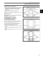
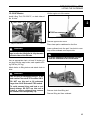
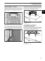
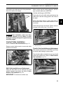
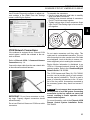
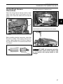
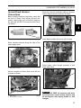
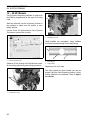
EMM CANbus connector cap is clipped to EMM
cooling water hose. Remove clip from cap and
install on I-Command harness connector.
1
2
If connecting to an existing Deutsch-style I-Command network, connect the purple wires between
the I-Command Ignition and Trim Harness and the
I-Command Engine Interface Cable. This connection supplies power to the network when the key
switch is on. Newer, quick connect-style networks
do not use this connection.
1
4
2
3
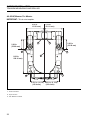
1. Canbus harness connector
2. EMM CANbus connector cap and clip
006743
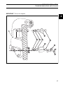
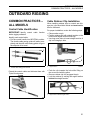
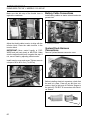
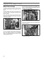
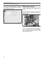
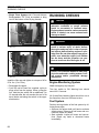
Install clip and connector to hose.
1
2
1.
2.
3.
4.
Trim/Tilt connector
I-Command Ignition connector
SystemCheck connector (with seal)
Network power supply connector
006734
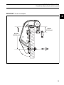
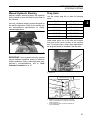
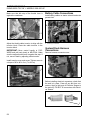
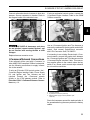
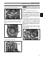
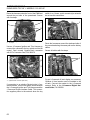
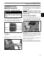
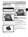
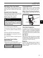
Route I-Command Ignition Harness through wire
channel in flywheel cover. Install electrical cover.
Make sure both harnesses are in front of the tab
and tighten with tie strap.
1
1. CANbus connectors
2. EMM cooling water hose
006744
ALL MODELS
3
2
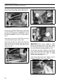
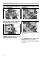
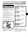
Adjust harness routing as needed and secure with
tie straps.
Use an I-Command Ignition and Trim Harness to
connect the outboard to the key switch and trim/tilt
control. Seal unused SystemCheck connector
with 6-Pin Connector Seal, P/N 586076.
4
1.
2.
3.
4.
Electrical cover
Wire channel
Tab
Tie strap
006737
69
3