1
CODE : 00ZMXM182/S1E
(With optional
SPF/RSPF installed)
DIGITAL MULTIFUNCTIONAL
SYSTEM
(With optional
SPF/RSPF installed)
MX-M182/M182D
MODEL
MX-M202D/M232D
MX-M182
MX-M182D
MX-M202D
MX-M232D
CONTENTS
[ 1 ] GENERAL . . . . . . . . . . . . . . . . . . . . . . . . . . . . . . . . . . . . . . . . . 1 - 1
[ 2 ] CONFIGURATION . . . . . . . . . . . . . . . . . . . . . . . . . . . . . . . . . . . 2 - 1
[ 3 ] SPECIFICATIONS . . . . . . . . . . . . . . . . . . . . . . . . . . . . . . . . . . . 3 - 1
[ 4 ] CONSUMABLE PARTS . . . . . . . . . . . . . . . . . . . . . . . . . . . . . . . 4 - 1
[ 5 ] EXTERNAL VIEWS AND INTERNAL STRUCTURES . . . . . . . 5 - 1
[ 6 ] ADJUSTMENTS . . . . . . . . . . . . . . . . . . . . . . . . . . . . . . . . . . . . 6 - 1
[ 7 ] SIMULATIONS. . . . . . . . . . . . . . . . . . . . . . . . . . . . . . . . . . . . . . 7 - 1
[ 8 ] TROUBLE CODE LIST . . . . . . . . . . . . . . . . . . . . . . . . . . . . . . . 8 - 1
[ 9 ] MAINTENANCE . . . . . . . . . . . . . . . . . . . . . . . . . . . . . . . . . . . . 9 - 1
[10] DISASSEMBLY AND ASSEMBLY . . . . . . . . . . . . . . . . . . . . . . 10 - 1
[11] OPERATIONAL DESCRIPTIONS . . . . . . . . . . . . . . . . . . . . . . 11 - 1
[12] FLASH ROM VERSION UP PROCEDURE. . . . . . . . . . . . . . . 12 - 1
[13] IP ADDRESS SETTING . . . . . . . . . . . . . . . . . . . . . . . . . . . . . 13 - 1
[14] ELECTRICAL SECTION . . . . . . . . . . . . . . . . . . . . . . . . . . . . . 14 - 1
Parts marked with “ “ are important for maintaining the safety of the set.
Be sure to replace these parts with specified ones for maintaining the safety and performance of the set.
SHARP CORPORATION
This document has been published to be used
for after sales service only.
The contents are subject to change without notice.
Disconnect the AC cord before servicing the unit.
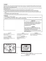
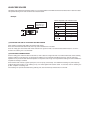
LASER WAVE - LENGTH : 785 15mm
Pulse times : 10.34 s 0.1 s/7mm ; MX-M182, MX-M182D, MX-M202D
8.665 s 0.1 s/7mm ; MX-M232D
Out put power : Max. 0.3mW
CONTENTS
[1] GENERAL
1. Note for servicing . . . . . . . . . . . . . . . . . . . . . . . . . . . . . . . 1 - 1
[2] CONFIGURATION
1. System Configurations . . . . . . . . . . . . . . . . . . . . . . . . . . . 2 - 1
[3] SPECIFICATIONS
1. Copy mode . . . . . . . . . . . . . . . . . . . . . . . . . . . . . . . . . . . . 3 - 1
2. Print mode . . . . . . . . . . . . . . . . . . . . . . . . . . . . . . . . . . . . 3 - 4
3. Scanner mode . . . . . . . . . . . . . . . . . . . . . . . . . . . . . . . . . 3 - 8
[4] CONSUMABLE PARTS
1. Supply system table . . . . . . . . . . . . . . . . . . . . . . . . . . . . . 4 - 1
2. Environmental conditions . . . . . . . . . . . . . . . . . . . . . . . . . 4 - 2
3. Production number identification . . . . . . . . . . . . . . . . . . . 4 - 3
[10] DISASSEMBLY AND ASSEMBLY
1. High voltage section/Duplex transport section . . . . . . . .10 - 1
2. Optical section . . . . . . . . . . . . . . . . . . . . . . . . . . . . . . . . .10 - 2
3. Fusing section . . . . . . . . . . . . . . . . . . . . . . . . . . . . . . . .10 - 4
4. Paper exit section . . . . . . . . . . . . . . . . . . . . . . . . . . . . . .10 - 7
5. MCU . . . . . . . . . . . . . . . . . . . . . . . . . . . . . . . . . . . . . . .10 - 10
6. Optical frame unit . . . . . . . . . . . . . . . . . . . . . . . . . . . . .10 - 10
7. LSU . . . . . . . . . . . . . . . . . . . . . . . . . . . . . . . . . . . . . . . .10 - 10
8. Tray paper feed section/Paper transport section . . . . .10 - 11
9. Bypass tray section . . . . . . . . . . . . . . . . . . . . . . . . . . .10 - 12
10. Power section . . . . . . . . . . . . . . . . . . . . . . . . . . . . . . . .10 - 14
11. Developing section . . . . . . . . . . . . . . . . . . . . . . . . . . . .10 - 15
12. Process section . . . . . . . . . . . . . . . . . . . . . . . . . . . . . . .10 - 16
[5] EXTERNAL VIEWS AND INTERNAL STRUCTURES
13. Others . . . . . . . . . . . . . . . . . . . . . . . . . . . . . . . . . . . . . .10 - 17
1. Appearance . . . . . . . . . . . . . . . . . . . . . . . . . . . . . . . . . . . 5 - 1
2. Internal . . . . . . . . . . . . . . . . . . . . . . . . . . . . . . . . . . . . . . . 5 - 2
3. Operation Section . . . . . . . . . . . . . . . . . . . . . . . . . . . . . . . 5 - 3
4. Motor, solenoid, clutch . . . . . . . . . . . . . . . . . . . . . . . . . . . 5 - 4
5. Sensor, switch . . . . . . . . . . . . . . . . . . . . . . . . . . . . . . . . . 5 - 5
6. PWB unit. . . . . . . . . . . . . . . . . . . . . . . . . . . . . . . . . . . . . . 5 - 6
7. Cross sectional view . . . . . . . . . . . . . . . . . . . . . . . . . . . . . 5 - 7
[6] ADJUSTMENTS
1. Adjustment item list. . . . . . . . . . . . . . . . . . . . . . . . . . . . . . 6 - 1
2. Copier adjustment. . . . . . . . . . . . . . . . . . . . . . . . . . . . . . . 6 - 1
[7] SIMULATIONS
1. Entering the simulation mode . . . . . . . . . . . . . . . . . . . . . . 7 - 1
2. Canceling the simulation mode. . . . . . . . . . . . . . . . . . . . . 7 - 1
3. List of simulations . . . . . . . . . . . . . . . . . . . . . . . . . . . . . . . 7 - 1
4. Contents of simulations . . . . . . . . . . . . . . . . . . . . . . . . . . 7 - 3
[8] TROUBLE CODE LIST
1. Trouble code list . . . . . . . . . . . . . . . . . . . . . . . . . . . . . . . . 8 - 1
2. Details of trouble codes . . . . . . . . . . . . . . . . . . . . . . . . . . 8 - 1
3. Communication result code . . . . . . . . . . . . . . . . . . . . . . . 8 - 6
[9] MAINTENANCE
1. Maintenance table . . . . . . . . . . . . . . . . . . . . . . . . . . . . . . 9 - 1
2. Maintenance display system . . . . . . . . . . . . . . . . . . . . . . 9 - 2
3. Note for replacement of consumable parts . . . . . . . . . . . 9 - 2
[11] OPERATIONAL DESCRIPTIONS
1. Paper feed operation . . . . . . . . . . . . . . . . . . . . . . . . . . . .11 - 1
[12] FLASH ROM VERSION UP PROCEDURE
1. Preparation . . . . . . . . . . . . . . . . . . . . . . . . . . . . . . . . . . .12 - 1
2. Download procedure . . . . . . . . . . . . . . . . . . . . . . . . . . . .12 - 1
3. Version confirming procedure . . . . . . . . . . . . . . . . . . . . .12 - 3
4. Facsimile Data upload procedure . . . . . . . . . . . . . . . . . .12 - 4
5. Updating the MX-NB12 firmware. . . . . . . . . . . . . . . . . . .12 - 5
6. Installation procedure . . . . . . . . . . . . . . . . . . . . . . . . . . .12 - 6
[13] IP ADDRESS SETTING
1. Setting the ip address of the machine by
system settings . . . . . . . . . . . . . . . . . . . . . . . . . . . . . . . .13 - 1
[14] ELECTRICAL SECTION
1. Block diagram . . . . . . . . . . . . . . . . . . . . . . . . . . . . . . . . .14 - 1
2. Actual wiring diagram . . . . . . . . . . . . . . . . . . . . . . . . . . .14 - 2
[1] GENERAL
•poorly ventilated
1. Note for servicing
Pictogram
The label (
) in the fusing area of the machine indicates the
following:
: Caution, risk of danger
: Caution, hot surface
A. Warning for servicing
•exposed to direct sunlight
•The fusing area is hot. Exercise care in this area when removing
misfeed paper.
•Do not disassemble the laser unit. Do not insert a reflective material
such as a screwdriver in the laser beam path.
It may damage eyes by reflection of laser beams.
B. Cautions for servicing
•Do not switch the machine rapidly on and off. After turning the machine
off, wait 10 to 15 seconds before turning it back on.
•Machine power must be turned off before installing any supplies.
•Place the machine on a firm, level surface.
•Do not install the machine in a humid or dusty location.
•When the machine is not used for a long time, for example, during
prolonged holidays, turn the power switch off and remove the power
cord from the outlet.
•When moving the machine, be sure to turn the power switch off and
remove the power cord from the outlet.
•Do not cover the machine with a dust cover, cloth or plastic film while the
power is on. Doing so may prevent heat dissipation, damaging the
machine.
•Use of controls or adjustments or performance of procedures other than
those specified herein may result in hazardous laser radiation
exposure.
•The socket-outlet shall be installed near the machine and shall be easily
accessible.
C. Note for installation place
Improper installation may damage the machine. Please note the
following during initial installation and whenever the machine is moved.
Caution : If the machine is moved from a cool place to a warm place,
condensation may form inside the machine. Operation in this
condition will cause poor copy quality and malfunctions. Leave
the machine at room temperature for at least 2 hours before
use.
Do not install your machine in areas that are:
•subject to extreme temperature or humidity changes, e.g., near an air
conditioner or heater.
The machine should be installed near an accessible power outlet for
easy connection and disconnection.
Be sure to connect the power cord only to a power outlet that meets the
specified voltage and current requirements. Also make certain the outlet
is properly grounded.
Note : Connect the machine to a power outlet which is not used for other
electric appliances. If a lighting fixture is connected to the same
outlet, the light may flicker.
Be sure to allow the required space around the machine for servicing
and proper ventilation.
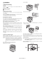
20 cm (8")
•damp, humid, or very dusty
20 cm
(8")
MX-M182 GENERAL 1-1
20 cm
(8")
D. Note for handling PWB and electronic parts
When handling the PWB and the electronic parts, be sure to observe the
following precautions in order to prevent against damage by static
electricity.
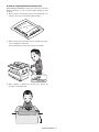
1) When in transit or storing, put the parts in an anti-static bag or an
anti-static case and do not touch them with bare hands.
2) When and after removing the parts from an anti-static bag (case),
use an earth band as shown below:
•Put an earth band to your arm, and connect it to the machine.
3) When repairing or replacing an electronic part, perform the
procedure on an anti-static mat.
MX-M182 GENERAL 1-2
[2] CONFIGURATION
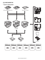
1. System Configurations
AR-VR7
(MX-M182 is standard.)
AR-SP10
AR-RP10
(MX-M182D/M202D/M232D only)
MX-NB12
MX-FX13
MX-M232D
MX-M202D
MX-M182
MX-M182D
MX-XB17
MX-EB14
AR-D36
AR-D37
MX-TR10
MX-PK10
MX-USX1
MX-USX5
MX-US10
MX-US50
MX-USA0
PS3 EXPANSION KIT
Sharpdesk 1 license kit
Sharpdesk 5 license kit
Sharpdesk 10 license kit
Sharpdesk 50 license kit
Sharpdesk 100 license kit
MX-M182 CONFIGURATION 2-1
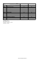
Model
Option
MX-M182
MX-M182D/M202D/M232D
AR-RP10
Reversing single pass feeder (RSPF)
X
O*1
AR-SP10
Single pass feeder (SPF)
O
O*2
AR-D36
250-sheet paper feed unit
O
O
AR-D37
2x250-sheet paper feed unit
O
O
AR-VR7
DOCUMENT COVER
STD
O*2
MX-NB12
NETWORK EXPANSION KIT
O
O
MX-FX13
FACSIMILE EXPANSION KIT
O*3
O*3
MX-XB17
FACSIMILE MOUNTING KIT
O
O
MX-TR10
JOB SEPARATOR
O
O
MX-EB14
EXPANSION MEMORY BOARD
O
O
MX-PK10
PS3 EXPANSION KIT
O*4
O*4
MX-USX1
SHARPDESK 1 LICENSE KIT
O
O
MX-USX5
SHARPDESK 5 LICENSE KIT
O
O
MX-US10
SHARPDESK 10 LICENSE KIT
O
O
MX-US50
SHARPDESK 50 LICENSE KIT
O
O
MX-USA0
SHARPDESK 100 LICENSE KIT
O
O
STD: Standard
O: Option installation enable
*1 Standard for U.S.A
*2 Not available for U.S.A
*3 MX-NB12 or MX-XB17 is required.
*4 MX-NB12 is required.
X: Option installation disable
MX-M182 CONFIGURATION 2-2
[3] SPECIFICATIONS
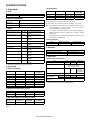
1. Copy mode
(4) Job efficiency
A. Type
Copy mode
Type
Paper exit
Desk-top
center tray / internal
S to S
S to D
D to D
B. Machine composition
MX-M182
MX-M182D
MX-M202D
MX-M232D
20-CPM multi function model
23-CPM multi function model
(1) Option
Model
AR-D36
2x250-sheet paper feed unit AR-D37
SPF
AR-SP10
RSPF*1
Network expansion kit
AR-RP10
MX-NB12
Document cover
Job separator
AR-VR7
MX-TR10
PS3 Expantion kit
MX-PK10
Facsimile expantion kit
MX-FX13
Facsimile mounting kit
MX-XB17
Expantion memory board
MX-EB14
MX-M182/M182D/M202D/
M232D
MX-M182/M182D/M202D/
M232D
MX-M182/M182D/M202D/
M232D
MX-M182D/M202D/M232D
MX-M182/M182D/M202D/
M232D
MX-M182D/M202D/M232D
MX-M182/M182D/M202D/
M232D
MX-M182/M182D/M202D/
M232D
MX-M182/M182D/M202D/
M232D
MX-M182/M182D/M202D/
M232D
MX-M182/M182D/M202D/
M232D
*1: Standard for North America and Latin America.
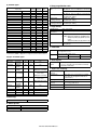
C. Copy speed
(1) Engine speed (ppm)
Paper size
MX-M232D
MX-M202D
A4/8.5" x 11"
A4R/8.5" x 11"R
A5/5.5"x8.5"
B5/16K
B5R/16KR
8.5"x13"
B4/8.5"x14"
A3/11"x17"/8K
23ppm
15/16ppm
23ppm
23ppm
18/16ppm
13ppm
13ppm
12/11/12ppm
20ppm
14/15ppm
20ppm
20ppm
16/15ppm
12ppm
12ppm
11/10/11ppm
23cpm machine
12ppm or more
23ppm
20cpm machine
12ppm or more
20ppm
S to S
MX-M232D
MX-M202D
20cpm (87%)
20cpm (100%)
18cpm (90%)
10cpm (50%)
10cpm (50%)
MX-M182
MX-M182D
18ppm
14/15ppm
18ppm
18ppm
16/15ppm
12ppm
12ppm
11/10/11ppm
(5) First copy time
Tray
1st tray
18/20cpm machine
7.2 sec or less
23cpm machine
5.9 sec or less
AE mode, A4/Letter, single surface copy with OC, in polygon ready state
D. Document
Max. document size
Document reference position
Detection (Platen)
A3, 11" x 17"
Upper left-hand corner
Yes
E. Paper feed
(1) Paper feed section details
Item
Paper capacity
Paper size detection
1st tray
2nd tray*1 Bypass tray
250 sheets 250 sheets 100 sheets
No
(Paper size is set with
the operasion panel.)
Paper type setting
No
No
No
(Heavy
paper setting
is enabled.)
Paper size changing method
The paper guide is set by the user.
Default paper size
AB series
A4
A4
when shipping
Inch series 8 1/2" x11" 8 1/2" x11"
Remaining paper quantity
Only empty detection available
detection
*1: 2-stage standard only for the MX-M202D/M232D
18cpm machine
12ppm or more
18ppm
(3) Document replacement speed (Copy mode)
Copy mode
18cpm (78%)
10cpm (43%)
10cpm (43%)
MX-M182
MX-M182D
15cpm (83%)
10cpm (56%)
10cpm (56%)
Note : The temperature at the end portion of the heat roller may rise too
high, depending on the kind of paper to be used, when in
continuous printing of small-size paper.
To avoid this, when the thermistor at the end portion detects a
higher temperature than the specified level, output is stopped
temporarily.
During temporary stop, Power Save Indicator lamp flashes in the
same manner as warming up.
(2) Engine performance when printing
Model
ROPM OFF
ROPM ON
MX-M202D
S to S : A4/8.5" x 11" document 10 sheets, copy 5 sets
S to D : A4/8.5" x 11" document 10 sheets, copy 5 sets
D to D : A4/8.5" x 11" document 10 sheets (20 pages), copy 5 sets
18-CPM multi function model
Machine
250-sheet paper feed unit
MX-M232D
MX-M182
MX-M182D
18cpm (100%)
S to S : A4/8.5" x 11" document 11 sheets, copy 1 set (Excluding the first
copy)
MX-M182 SPECIFICATIONS 3-1
(2) Feedable paper
H. Copy magnification ratio
Paper size
A3
B4
A4
A4-R
B5
B5R
A5
A5R
A6R
B6R
Ledger 11x17 in
Legal 8.5x14in.
8.5x13.4 *1
Foolscap 8.5x13 in
Letter 11x8.5in
Letter-R 8.5x11in
Executive-R 7.25x10.5in.
Invoice 8.5x5.5 in.
Invoice-R 5.5x8.5 in
8K
16K
16KR
COM10
1st tray 2nd tray
297x420
257x364
297x210
210x297
257x182
182x257
210x148.5
148.5x210
105x148.5
128.5x182
279.4x431.8
215.9x355.6
216x340 *1
215.9x330.2
279.4x215.9
215.9x279.4
184.2x266.7
215.9x139.7
139.7x215.9
270x390
270x195
195x270
104.8x241.3
Yes
Yes
Yes
Yes
Yes
Yes
Yes
N/A
N/A
N/A
Yes
Yes
*1
Yes
Yes
Yes
N/A
Yes
N/A
Yes
Yes
Yes
N/A
Yes
Yes
Yes
Yes
Yes
Yes
N/A
N/A
N/A
N/A
Yes
Yes
*1
Yes
Yes
Yes
N/A
N/A
N/A
Yes
Yes
Yes
N/A
Bypass
tray
Yes
Yes
Yes
Yes
Yes
Yes
Yes
Yes
Yes
Yes
Yes
Yes
*1
Yes
Yes
Yes
Yes
Yes
Yes
Yes
Yes
Yes
Yes
*1: Switches by SIM26-2. (Operation UI supports by 8.5x13 and exclusion.)
(3)Types of feedable paper
Types of paper
1st tray 2nd tray
Bypass tray
Thin paper
56-59g/m2
Yes
Yes
Yes
15-15.9lbs
Plain paper
60-90g/m2
Yes
Yes
Yes
16-24lbs
Heavy paper 91-105g/m2
N/A
N/A
Yes
16-24lbs
(Multi paper feed enable)
Heavy paper 106-128g/m2
N/A
N/A
Yes
24.1-33.5lbs
(A4 or less)
(Multi paper feed enable)
Heavy paper 129-200g/m2
N/A
N/A
Yes
33.6-53.2lbs
(A4 or less)
(Only single paper feed)
Heavy paper 201-256g/m2
N/A
N/A
N/A
53.3-68lbs
Envelope
75-90g/m2
N/A
N/A
Yes
20-24lbs
Postcard
N/A
N/A
Yes
OHP film
N/A
N/A
Yes
Label sheet
N/A
N/A
Yes
Tab paper 20
N/A
N/A
N/A
Fixed magnification
ratio
AB system:
400, 200, 141, 122, 115, 100, 86, 81, 70, 50, 25%
Inch system:
400, 200, 141, 129, 121, 100, 95, 77, 64, 50, 25%
Zooming
25 ~ 400%
SPF/RSPF (50 ~ 200%)
Independent
Available (25 ~ 400%)
zooming (vertical)
SPF/RSPF (50 ~ 200%)
Independent
Available (25 ~ 400%)
zooming (horizontal) SPF/RSPF (50 ~ 200%)
I. Copy density
Density mode
No. of manual
adjustment
Resolution
J. Void width
Void area
Lead edge 1 ~ 4mm
Rear edge 4mm or less
Total of both sides: 6mm or less
Image loss OC
Same size
SPF/RSPF
Same size
3mm or less
4mm or less
K. Auto duplex
Standard/
Option
Standard provision (MX-M182D/M202D/M232D only)
(D D / D S enable only when RSPF is installed)
Not available for MX-M182
L. Paper exit / finishing
Paper exit section
capacity
Full detection
Finishing
Electronic sort
capacity
Offset function
Staple function
999 sheets
G. Warm-up time
Warm-up time
Pre-heat
Jam recovery
Writing: 600 x 600dpi
Reading: 400 (main) x 600 (sub) (PHOTO mode)
400 (main) x 600 (sub) (AUTO exposure
mode)
400 (main) x 600 (sub) dpi (TEXT mode)
Reading: 256 gradations
Writing: Binary
Gradation
F. Multi copy
Max. number of multi copy
Auto / Text / Photo
5 steps (Text / Photo)
25 seconds or less
Available
Within 25 sec
MX-M182 SPECIFICATIONS 3-2
Face down 250 sheets
Upper stage: Yes (Job separator is installed)
Lower stage: No (Copy/printer 250 sheets
count detection)
None
A4/ 8.5" x 11" standard document
(6% coverage) 160 sheets
Yes
None
M. Additional functions
N. Other specifications
MX-M182D/M202D/
M232D
MX-M182
APS
AMS
Auto tray switching
Memory copy
Rotation copy
E-sort
(Sorting function)
E-sort
(Grouping function)
Rotation sort
Prevention of sky shot
Independent zooming
1 set 2 copy
Binding margin
Edge erase
Center erase
Black/white reverse
2in1/4in1
Offset
Preheating
Auto shut-off
System setting
Counter
Coin vendor support
Auditor support
Duplex
Toner save
Account control
O : Available
O
O
O
O
O
Photoconductor type
Photoconductor drum dia.
Copy lamp
Developing system
Charging system
Transfer system
Separation system
Fusing system
Cleaning system
O
O
X
X
O
O. Package form
O
SPF/RSPF: Disable
OC: Enlargement is
disable.
O
Default AB series: 10mm
(5, 10, 15, 20mm)
Inch series: 1/2 inch
(1/4, 1/2, 3/4, 1 inch)
X
O
O
O
The conditions are set by the system setting.
O
The conditions are set by the system setting.
O
O
(1) Copy total
(2) Print total
(3) Scan
(4) Toner residual quantity
O
(Supporting the interface only)
O
(Supporting the interface only)
X
O
O
(Set according to the destination)
O
(Copy/Printer/Scanner Number of control: 50)
P. External view
O
SPF: Disable
OC: Enlargement is
disable.
X : Not available
Body
OPC (Organic Photo Conductor)
30mm
WhiteCCFL
Dry 2-component magnetic brush
development
Saw teeth charging
(+) DC corotron
(-) DC corotron
Heat roller
Contact blade
Body / Accessories
External dimensions
(With the bypass tray closed)
Occupying area
(With the bypass tray opened)
Weight
(Excluding developer)
Standard model
D model
591mm(W) x 573mm(D)
883mm(W) x 573mm(D)
1-tray model:
29.4kg
1-tray model:
29.6kg (OC)
2-tray model:
35.0kg (OC)
1-tray model:
33.2kg (RSPF)
2-tray model:
38.6kg (RSPF)
Q. Power source
Voltage
Frequency
100 - 127V 220 - 240V
50/60Hz common
R. Power consumption
Max. power consumption
1200W
S. Digital performance
Resolution
Gradation
Memory (MAX)
Hard disk
MX-M182 SPECIFICATIONS 3-3
Reading
400 x 600dpi (PHOTO mode)
400 x 600dpi (AUTO exposure mode)
400 (main) x 600 (sub) dpi (TEXT mode)
Writing
600 x 600dpi
Reading
256 gradations
Writing
Binary
256MB (with MX-EB14)
None
2. Print mode
A. Printing function
(1) Platform
Item
Support platform
Content
IBM PC/AT compatible machine
(2) Support OS
Main unit
OS
Windows
Mac
98/Me
NT 4.0 SP5 or later
2000
XP
XPx64
Server 2003
Server 2003x64
Vista
Vistax64
Server 2008
Server 2008x64
Windows 7
Windows 7x64
9.0-9.2.2
X 10.2.8
X 10.3.9
X 10.4.11
X 10.5- 10.5.8
X 10.6-10.6.4
Twain/Button
Manager
No
No
CD-ROM
CD-ROM
CD-ROM
No
No
CD-ROM
CD-ROM
No
No
CD-ROM
CD-ROM
No
No
No
No
No
No
When MX-FX13 is
installed
When MX-NB12 is installed
SPLC
No
No
CD-ROM
CD-ROM
CD-ROM
No
No
CD-ROM
CD-ROM
No
No
CD-ROM
CD-ROM
No
No
No
No
No
No
Custom
PCL6
No
No
CD-ROM
CD-ROM
CD-ROM
CD-ROM
CD-ROM
CD-ROM
CD-ROM
CD-ROM
CD-ROM
CD-ROM
CD-ROM
No
No
No
No
No
No
Custom
PCL5e
No
No
No
No
No
No
No
No
No
No
No
No
No
No
No
No
No
No
No
Custom
PS
No
No
CD-ROM
CD-ROM
CD-ROM
CD-ROM
CD-ROM
CD-ROM
CD-ROM
CD-ROM
CD-ROM
CD-ROM
CD-ROM
No
No
No
No
No
No
PPD
PC-FAX
No
No
CD-ROM
CD-ROM
CD-ROM
CD-ROM
CD-ROM
CD-ROM
CD-ROM
CD-ROM
CD-ROM
CD-ROM
CD-ROM
No
Web
Web
CD-ROM
CD-ROM
CD-ROM
No
No
CD-ROM
CD-ROM
CD-ROM
CD-ROM
CD-ROM
CD-ROM
CD-ROM
CD-ROM
CD-ROM
CD-ROM
CD-ROM
No
No
No
No
No
No
(3) Printer driver function
a. Windows version of SPLC driver
Main
Function
Copies
Collate
Document Style
N-up
N-up Order
N-up Border
User Setting
Image Orientation
Paper
Rotate 180 Degree
Paper Size (paper size)
Custom Paper Size
(paper size)
Fit to Page
(Zoom setting)
Zoom (Zoom setting)
Fit to Page size
(Zoom setting)
Paper Selection
Output
Overseas
1-999
Collate
Uncollate
1-sided
2-sided (Book)
2-sided (Tablet)
2/4/6
Z
Yes / No
Add/Delete
Portrait
Landscape
Yes / No
A3 / B4 / A4 / B5 / A5 / A6 / B6 / Ledger /
Legal/ 8.5x13.4 / Foolscap / Folio / Letter /
Invoice / Executive / 8K / 16K / COM-10 /
DL / C5 / A2(Fit To Page) / Custom *1
1 size
Yes/No
Description
Perform specified numbers of printing.
If "Collate" is specified, plural printing by the number of set is done,
and "Uncollate" is specified, plural printing by page is done.
Simplex or duplex printing is done depending on the setting.
Print direction is different depending on book/tablet for duplex
printing. (* Simplex model have no duplex function.)
Specified numbers of pages are printed on one sheet.
Partition line is added for the plural pages printed on 1 sheet.
Register the setting value for commonly-used driver.
Print in the specified print direction.
Rotate data 180 degrees to print.
Print in the specified paper size. Even if actual paper size is different
from the specified paper size, the image is created in the specified
paper size to print.
Width: 100 - 297mm
Length: 148 - 431.8mm
Print size is changed according to the specified contents.
25-400%
A3 / B4 / A4 / B5 / A5 / A6 / B6 / Ledger /
Legal / 8.5x13.4/ Foolscap / Folio / Letter /
Invoice / Executive / 8K / 16K / COM-10 /
DL / C5
Auto
Paper is fed from the specified paper feed tray.
Bypass (Auto)
Bypass (Manual)
Tray 1/2 (3/4)
Center Tray / Upper Tray
MX-M182 SPECIFICATIONS 3-4
Function
Advanced Brightness
(Image adjustment)
Overseas
0 - 100%
Contrast
(Image adjustment)
0 - 100%.
Text To Black
Water
marks
Option
Vector To Black
Input Resolution
(compatibility)
Hatching Pattern
(compatibility)
Spool format
(compatibility)
Reduction Method
(compatibility)
Print density
(compatibility)
Duplex print
(Compatibility)
Duplex Style
(compatibility)
Print by number of copy
(compatibility)
Watermark
Yes / No
600dpi/300dpi
Description
Adjust the brightness of the image by moving the scale within the
range of 0-100. The illustration image at the upper left of the screen
changes by this adjustment.
Adjust the contrast of the image by moving the scale within the range
of 0-100. The illustration image at the upper left of the screen
changes by this adjustment
Print documents created by CAD software in B/W to improve
visualization of colored line image/text.
Print lines in BW to improve visualization.
Select input resolution (default: 600dpi)
Standard/fine
Select hatching pattern (default: standard)
Yes / No
RAW/EMF
Standard/By Object/ By page
1 - 5 stages
Yes / No
Pattern1/ Pattern2/ Pattern3
Yes / No
None / TOP SECRET / CONFIDENTIAL /
DRAFT / ORIGINAL / COPY
User Setting
Add / Update / Delete
Position
Center
X: ±50
Y: ±50
Size
6 - 300
Angle
±90
Grayscale
0 - 255
Edit Font
Yes
Thick Letter
Yes/No
Italic Face
Yes/No
Character Set
Yes
On First Page only
Yes / No
ROPM
On/Off
Paper Feed Option
1-Tray/2-Tray/3-Tray/4-Tray
Auto Configuration
Yes
Paper Tray (Tray Setting)
Bypass Tray/Tray1/Tray2/Tray3/Tray4
Paper Size to Specify
No specification/ A3 / B4 / A4 / B5 / A5 /
A6 / B6 / Ledger / Legal / 8.5x13.4 /
Foolscap / Folio / Letter / Invoice /
Executive / 8K / 16K / COM-10 / DL / C5 /
Custom
Status Window
Yes
Version Information
Yes
Default: RAW
Default: Standard
Default: 3
Specify duplex printing function with giving priority to driver.
Default: 1
Specify print by set function with giving priority to driver.
Select watermark specified as default.
Add, register and delete watermark.
Adjust the position of watermark vertically and horizontally.
Adjust the size of watermark.
Adjust the angle of watermark.
Adjust the watermark density.
Edit font.
Put watermark only on the first page.
*1: Custom paper size range: Width 100 - 297.0 mm (3.94 -11.69 inch) Length 148 -431.8mm (5.83 - 17.00 inch)
MX-M182 SPECIFICATIONS 3-5
b. Windows version of PCL/PS Driver (PCL: MX-NB12 is expanded)
Function
Main
Paper
Advanced
PCL6
PS
1-999
1-999
Portrait
Portrait
Landscape
Landscape
Rotate 180 Degree
Yes / No
Yes / No
Collate
Collate
Collate
Uncollate
Uncollate
Document Style
1-Sided, 2-Sided(Book) 2-Sided(Tablet),
1-Sided, 2-Sided(Book) 2-Sided(Tablet),
Pamphlet Style (Tiled Pamphlet),
Pamphlet Style (Tiled Pamphlet),
Pamphlet Style (2-up Pamphlet)
Pamphlet Style (2-up Pamphlet)
Job Control Inform job end
Yes/No
Yes/No
Account Number Setting
Yes/No (5 digits)
Yes/No (5 digits)
Confirm Job Control
Yes/No
Yes/No
Binding Edge
N/A
N/A
Margin Shift
N/A
N/A
N-up
N-up
2/4/6/8/9/16
2/4/6/8/9/16
N-up Order
Z
Z
N-up Border
Yes/No
Yes/No
Paper Size
Paper Size
A3 / B4 / A4 / B5 / A5 / B6 / A6 / 11x17 /
A3 / B4 / A4 / B5 / A5 / B6 / A6 / 11x17 /
8.5x14 / 8.5 x 13.4/ 8.5x13 / 8.5x11 / 5.5x8.5 / 8.5x14 / 8.5 x 13.4/ 8.5x13 / 8.5x11 / 5.5x8.5 /
Folio / Executive / COM-10 / DL / C5/ 8K /
Folio / Executive / COM-10 / DL / C5 / 8K /
16K / A0 (Fit To Page) / A1(Fit To Page)/
16K / Custom *1
A2(Fit To Page) / Custom *1
Paper Type
N/A
N/A
Custom Paper Size
1 size
1 size
Zoom Setting Fit to Page
Yes/No
Yes/No
Zoom
25-400%
N/A
Reference Point: Upper left/Center
XY-Zoom
N/A
Width: 25 - 400%
Length: 25 - 400%
Lock Aspect Ratio: On/Off
Reference Point: Upper left/Center
Fit to Page size
A3 / B4 / A4 / B5 / A5 / B6 / A6 / 11x17 /
A3 / B4 / A4 / B5 / A5 / B6 / A6 / 11x17 /
8.5x14 / 8.5 x 13.4 / 8.5x13 / 8.5x11 /
8.5x14 / 8.5 x 13.4 / 8.5x13 / 8.5x11 /
5.5x8.5 / Folio / Executive / COM-10 / DL /
5.5x8.5 / Folio / Executive / COM-10 / DL /
C5 / 8K / 16K
C5 / 8K / 16K
Paper Selection
Auto
Auto
Bypass (Auto)
Auto Bypass (Auto)
Bypass (Manual)
Bypass (Manual)
Tray 1/2/3/4
Tray 1/2/3/4
Graphics mode
Raster/Vector
N/A
Mirror Image
N/A
Horizontal Vertical
PostScript
PS Error Information
N/A
Yes/No
Option
PS Pass-Through
N/A
Yes/No
Bitmap Compression
None / Very High Quality / High Quality /
N/A
Medium Quality / Draft
Compression Job Compression
N/A
None / Fastest / Fast / Medium /
Options
Best Compression
Bitmap Compression
N/A
None / Very High Quality / High Quality /
Medium Quality / Draft
Compatibility Input Resolution
600/300 dpi
N/A
Halftone Setting
N/A
N/A
Hatching Pattern
Standard/Fine
N/A
Spool Format
RAW/EMF
N/A
Print Density
1-5 Stages
1-5 Stages
Print by set (Give priority
Yes / No
N/A
to Driver Setting)
Duplex Printing (Give
Yes / No
N/A
Priority to Driver Setting)
Negative Image
N/A
N/A
Mirror Image
N/A
N/A
Zoom
N/A
N/A
Duplex Style
Pattern1/ Pattern2/ Pattern3
Pattern1 / Pattern2 / Pattern3
Overlay
ON/OFF
ON/OFF
Font Setting
Yes
Yes
Resident Font: 80 fonts
Resident Font: 80 fonts
Copies
Image
Orientation
MX-M182 SPECIFICATIONS 3-6
Advanced
Water marks
Special Mode
Option
PCL6
PS
0 - 100%
0 - 100%
0 - 100%
0 - 100%
Text To Black
Yes / No
Yes / No
Vector To Black
Yes / No
Yes / No
Right binding
Yes/No
Yes / No
Watermark
None / TOP SECRET / CONFIDENTIAL /
None / TOP SECRET / CONFIDENTIAL /
DRAFT / ORIGINAL / COPY
DRAFT / ORIGINAL / COPY
User Setting
Add / Update / Delete
Add / Update / Delete
Position
Center
Center
X: ±50
X: ±50
Y : ±50
Y : ±50
Size
6 - 300
6 - 300
Angle
±90
±90
Grayscale
0 - 255
0 - 255
Edit Font
Yes
Yes
Thick Letter
Yes/No
Yes/No
Italic Face
Yes/No
Yes/No
Character Set
Yes
Yes
Print Pattern
Transparent 1 / Transparent 2 / Overlap /
Transparent / Overlap / Outline
Outline
Frame Line
None/rectangle/Circle
None/rectangle/Circle
On First Page only
Yes / No
Yes / No
Page Interleave
Yes
N/A
Paper
Different 1st (Cover) and
1st Page: On/Off
1st Page : On/Off
Insertion
Last Page
(Last Page Not Support)
(Last Page Not Support)
Setting
Duplex Printing
Yes/No
Yes/No
Paper Tray
Bypass (Auto)
Bypass (Auto)
Bypass(Manual)
Bypass(Manual)
Tray 1/2/3/4
Tray 1/2/3/4
Transparency Inserts
N/A
N/A
Carbon Copy
N/A
N/A
ROPM
On/Off
On/Off
Paper Feed Option
1-Tray/2-Tray/3-Tray/4-Tray
1-Tray/2-Tray/3-Tray/4-Tray
Job Separator
On/Off
On/Off
Option Auto Setting
Yes
Yes
Tray Setting Paper Tray
Bypass Tray/ Tray1/Tray2/Tray3/Tray4
Bypass Tray/ Tray1/Tray2/Tray3/Tray4
Paper Size to Specify
Not Specified/ A3 / B4 / A4 / B5 / A5 / A6 /
Not Specified/ A3 / B4 / A4 / B5 / A5 / A6 /
B6 / Ledger / Legal / 8.5x13.4 / Foolscap /
B6 / Ledger / Legal / 8.5x13.4 / Foolscap /
Folio / Letter / Invoice / Executive / 8K / 16K / Folio / Letter / Invoice / Executive / 8K / 16K /
COM-10 / DL / C5 / Custom)
COM-10 / DL / C5 / Custom)
Print Policy
Yes
Yes
Font
N/A
Yes
Version Information
Yes
Yes
Image
Adjustment
Function
Brightness
Contrast
*1: Custom paper size range: Width 100 - 297.0 mm (3.94 -11.69 inch) Length 148 -431.8mm (5.83 - 17.00 inch)
MX-M182 SPECIFICATIONS 3-7
C. Windows version/Mac version of PPD Driver
(2) Support Image (MX-NB12 is expanded)
Function
WinPPD
Mac PPD
Copies
Yes
Yes
Collate/Uncollate
Yes
Yes
N-UP
Yes
Yes
N-up Order
No
Yes
N-up Border
No
Yes
Duplex
Yes
Yes
Retention
No
No
Document Filling
No
No
User Authentication
No
No
User Number
No
Yes
Job ID (User Name/
No
Yes
Job Name)
Color Mode
No
No
Print Mode
No
No
Image Type
No
No
Neutral Gray
No
No
Pure Black Print
No
No
Black Over Print
No
No
Toner Save
No
No
Color Adjustment
No
No
Source Profile
No
No
Rendering Intent
No
No
Output Profile
No
No
Screening
No
No
Simulation Profile
No
No
Paper Size
A3 / B4 / A4 / B5 / A5 / A3 / B4 / A4 / B5 / A5 /
B6 / A6 / 11x17 /
B6 / A6 / 11x17 /
8.5x14 / 8.5 x 13.4/
8.5x14 / 8.5 x 13.4/
8.5x13 / 8.5x11 /
8.5x13 / 8.5x11 /
5.5x8.5 / Folio /
5.5x8.5 / Folio /
Executive / COM-10 /
Executive / COM-10 /
DL / C5/ 8K / 16K/
DL / C5 / 8K / 16K /
Custom*1
A0 (Fit To Page) / A1 (Fit
To Page) / A2 (Fit To
Page) / Custom*1
Output Tray
Upper Tray Center Tray Upper Tray Center Tray
Mode
Mode
Scanner
File Format
(MX-NB12 is (B/W)
expanded)
*1: Custom paper size range: Width 100 - 297.0 mm (3.94 -11.69 inch)
Length 148 -431.8mm (5.83 - 17.00 inch)
A. Scanner function
(1) Mode
Twain Scan
(Including Button
Manager)
Sub Mode
E-mail
FTP Server
Network Folder (SMB)
Desktop
USB Memory
–
Yes
(MX-NB12 is expanded)
No
Yes
(MX-NB12 is expanded)
Support
Yes
Yes
N/A
N/A
N/A
Yes
Yes
Yes
N/A
N/A
N/A
N/A
Yes
Yes
Yes
N/A
N/A
N/A
N/A
(3) Image Processing
Mode
Exposure Adjustment
Auto
Manual
Original Type *1
Text
Photo
Auto
Resolution (Different depending on
file format/ sending method)
Scanner (MX-NB12 is expanded)
Yes
5 levels
Yes
Yes
Yes
75 x 75 dpi
100x100dpi
150x150dpi
200x200dpi
300x300dpi
400x400dpi
600x600dpi
*1: This setting can only be set at the B/W mode
(4) Push Scan (Button Manager)
Support OS
3. Scanner mode
Mode
Scanner
Type
TIFF
PDF
PDF/A
Encrypted PDF
XPS
File Format TIFF
(Gray Scale) JPEG
PDF
PDF/A
Encrypted PDF
Compact PDF (ACRE installed)
XPS
File Format TIFF
(Color)
JPEG
PDF
PDF/A
Encrypted PDF
Compact PDF (ACRE installed)
XPS
Windows 2000 Professional/Windows XP Home Edition/
Windows XP Professional/Windows Vista/Windows 7
Hardware
(System) Shall meet the operating conditions of each OS
Environment
basically.
(HDD)
8MB or more: 100MB or more is recommended
(Monitor) 800x600 dots or more
Shall be able to display 256 colors or more.
(Other) USB port (2.0)
Selectable
Sharpdesk/ E-mail software/ Fax software/ OCR
destination software/ MS Word/ Any directory
File Format TIFF/PDF/BMP
Yes
MX-M182 SPECIFICATIONS 3-8
(5) Pull Scan (TWAIN)
USB TWAIN (Does not function in Network system)
Windows 2000 Professional/Windows XP Home Edition/ Windows XP Professional/ Windows Vista/Windows 7
USB
(System) Shall meet the operating conditions of each OS basically.
(HDD) 8MB or more: 100MB or more is recommended
(Monitor) 800x600dots or more
Shall be able to display 256 colors or more.
(Other) USB port
Two-sided Scan
Yes
Color Mode
B/W(Mono2)/ B/W(Error Diffusion)/Gray Scale/Full Color
Resolution
75dpi/ 100dpi/ 150dpi/ 200dpi/ 300dpi/ 400dpi/ 600dpi Or Custom: 50 - 9600dpi (simulated)
Scanning Range
A3/ A4/ A4-R/ A5/ A5-R/ B4/ B5/ B5-R/ Ledger/ Letter/ Letter-R/ Executive/ Executive-R/ Foolscap/ Invoice/
Invoice-R/ Legal/ 8.5x13.4/ 8.5x13.5(343x216mm)/ Postcard/ 8K/ 16K/ 16K-R/ Auto/ User Definition
Preview Function
Yes
Zoom Preview Function
Yes
Rotation Scan
Yes (90 / 180/ 270 degrees)
Quick Scan
No
Brightness/Contrast Adjustment
Auto/ Manual(-100 - +100)
Gamma Adjustment
Yes
Color Matching
None/ Printer/ CRT/ LCD display/ ICM
Edge Emphasis
None/ Normal/ High/ Fuzzy
B/W Reverse
Yes
Selection of Light Source Color
Yes (Red/ Green/ Blue/ White)
Threshold Setting
Auto/ Manual (1-254)
Addition of Void Area
Available (Lead Edge/Trail Edge: 2.5mm Right/Left: 3.0mm)
Storing of Setting Contents
Yes
Keeping of Preview Image
Yes
Unit of Display for Scanning Range Pixel/ mm/ inch
Notes' Security Feature
No
Support OS
Interface
Hardware Environment
(6) Network Push Scan (MX-NB12 is expanded)
a. Specification
Support OS
Scan Resolution
Interface
Support Server/Protocol
Output file format
2-sided original scan
Optical Resolution
File creation
Sending method/Linkage
Density
Light Source
Void Area
Control System
Recommended Web browser
Support Mail system
Addressing
Number of registration of
destination
Utility
Windows 2000 Professional/Windows XP Home Edition/ Windows XP Professional/Windows Vista/Windows 7
75x75, 100x100, 150x150, 200x200, 300x300, 400x400, 600x600dpi (main direction x sub direction)
USB 2.0, 10/100BASE-TX
TCP/IP, SMTP, LDAP, FTP
B&W : PDF (w/o compression, G3, G4), TIFF (w/o compression, G3, G4)
Color/Gray scale: JPEG, PDF(JPEG), TIFF(JPEG)
TIFF/PDF supports multi page.
Yes
400x600dpi
File per 1 to 6 page / 1 file for all pages
File server sending scan
Desktop sending scan
E-mail sending scan
USB memory scan
1-5
Yes (Red/ Green/ Blue/ White)
Yes
Embedded Web server
Internet Explorer6.0 or later
Mail server supporting SMTP, Mail server supporting POP3
Rapid / Group / Indication by Direct Address Input / Selection from LDAP Server
Max. 200 All destination including E-mail, File server, Desktop and Group. Multiple E-mail addresses can be
registered as a group and as 1 destination (max. 100). In this case, number of registration of destination may be
less than 200.
Sharpdesk
MX-M182 SPECIFICATIONS 3-9
b. Scanner Setting
Key
Color Mode
Color Mode
Grouping
Format
Format and Compression method
Multi-file/Single file
Resolution
Resolution
Duplex
1-side / 2-sided original
Original size
Vertical original (set vertical)
Horizontal original (set vertical)
Vertical original (set horizontal)
Horizontal original (set horizontal)
Scan size
Selectable items
*Color
Gray
Monochrome
TIFF
TIFF G3
TIFF G4
*PDF
PDF G3
PDF G4
JPEG
Single : 1 page / file
*Multi : All pages / file
Multi : 2 pages / file
Multi : 3 pages / file
Multi : 4 pages / file
Multi : 5 pages / file
Multi : 6 pages / file
75dpi
100dpi
*150dpi
200dpi
300dpi
400dpi
600dpi
*1-side
2-sided
Vertical original (set vertical)
Horizontal original (set vertical)
Vertical original (set horizontal)
Horizontal original (set horizontal)
A3/B4/A4/A4R/B5/B5R/A5/A5
MX-M182 SPECIFICATIONS 3-10
Remark
Set the scan color
*Default is Color.
Specify file format.
*Default is PDF
Specify Single or Multi.
Single: 1 page / file
Multi: Plural pages / file
*Default: All pages / file
Set the output resolution
*Default: 150dpi
Set the original type whether 1-side or 2-sided.
This menu will appear when RSPF is installed.
If 2-sided is specified, original is scanned only by RSPF.
*Default: 1-side
Set the scan size.
[4] CONSUMABLE PARTS
1.Supply system table
A. North America, Middle America, South America
No.
Name
Product name
Content
Life
1
Toner cartridge(Black)
MX-235NT
Toner cartridge
Vinyl bag
x1
x1
16K
Default is Toner save
mode. Life is 19K.
(200V series)
2
Developer
MX-235NV
Developer
x1
50K
3
Drum KIT
AR-205DR
Drum
Drum fixing plate
x1
x1
50K
Remark
Life setting by A4 6% document
B. Brazil
No.
Name
Product name
Content
Life
1
Toner cartridge(Black)
MX-235BT
Toner cartridge
Vinyl bag
x1
x1
16K
2
Developer
MX-235NV
Developer
x1
50K
3
Drum KIT
AR-205DR
Drum
Drum fixing plate
x1
x1
50K
Remark
Life setting by A4 6% document
C. Europe
No.
Name
Product name
Content
Life
1
Toner cartridge(Black)
MX-235GT
Toner cartridge
Vinyl bag
x1
x1
16K
2
Developer
MX-235GV
Developer
x1
50K
3
Drum KIT
AR-205DM
Drum
Drum fixing plate
x1
x1
50K
Remark
Life setting by A4 6% document
D. Australia/New Zealand
No.
Name
Product name
Content
Life
1
Toner cartridge(Black)
MX-235GT
Toner cartridge
Vinyl bag
x1
x1
16K
2
Developer
MX-235GV
Developer
x1
50K
3
Drum KIT
AR-205DM
Drum
Drum fixing plate
x1
x1
50K
Remarke
Life setting by A4 6% document
E. Middle East, Africa (except Iran) /Israel/Philippines/Others
No.
Name
Product name
Content
Life
Remark
1
Toner cartridge(Black)
MX-235FT
Toner cartridge
Vinyl bag
x1
x1
16K
Life setting by A4 6% document
2
Toner cartridge(Black)
MX-236FT
Toner cartridge
Vinyl bag
x1
x1
8.4K
Life setting by A4 6% document
3
Developer
MX-235FV
Developer
x1
50K
4
Drum KIT
AR-205DR
Drum
Drum fixing plate
x1
x1
50K
F. Taiwan
No.
Name
Product name
Content
Life
Remark
1
Toner cartridge(Black)
MX-235FT
Toner cartridge
Vinyl bag
x1
x1
16K
Life setting by A4 6% document
2
Toner cartridge(Black)
MX-236FT
Toner cartridge
Vinyl bag
x1
x1
8.4K
Life setting by A4 6% document
3
Developer
MX-235FV
Developer
x1
50K
4
Drum KIT
AR-205DR
Drum
Drum fixing plate
x1
x1
50K
MX-M182 CONSUMABLE PARTS 4-1
G. Asia(Except the above)/Thailand/Hong Kong
No.
Name
Product name
Content
Life
Remark
1
Toner cartridge(Black)
MX-235AT
Toner cartridge
Vinyl bag
x1
x1
16K
Life setting by A4 6% document
2
Toner cartridge(Black)
MX-236AT
Toner cartridge
Vinyl bag
x1
x1
8.4K
Life setting by A4 6% document
3
Developer
MX-235AV
Developer
x1
50K
4
Drum KIT
AR-205DR
Drum
Drum fixing plate
x1
x1
50K
2. Environmental conditions
A. Transport conditions
B. Use conditions
Humidity (%)
Humidity (%)
(1) Transport conditions
Use environment
conditions
Temperature
Temperature
C. Life(packed conditions)
Photoconductor drum (36 months from the production month)
Developer, toner (24 months from the production month)
Humidity (%)
(2) Storage conditions
Temperature
MX-M182 CONSUMABLE PARTS 4-2
3. Production number identification
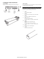
<Toner cartridge>
<Drum cartridge>
The label on the toner cartridge shows the date of production.
The lot number, printed on the front side flange, is composed of 10 digits,
each digit showing the following content:
1
2
3
4
5
6
7
8
9
10
The lot number is of 10 digits. Each digit indicates the content as follows.
The number is printed on the flange on the front side.
Production
place
Serial
number
Year/
Month/
Day
Ver.No.
1:
Number
For this model, this digit is 2.
2:
Alphabet
Indicates the model conformity code. G for this model.
3:
Number
Indicates the end digit of the production year.
4:
Number or X, Y, Z
Indicates the production month.
X stands for October, Y November, and Z December.
5/6:
Number
Indicates the day of the production date.
7:
Number
Indicates the day of the month of packing.
X stands for October, Y November, and Z December.
8/9:
Number
Indicates the day of the packing date.
10:
Alphabet
Indicates the production factory.
MX-M182 CONSUMABLE PARTS 4-3
[5] EXTERNAL VIEWS AND INTERNAL STRUCTURES
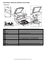
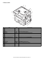
1. Appearance
3
13
8
9
7
4
5
5
14
1
6
10
15
2
12
11
16
17
18
1
USB 2.0 port
Connect to your computer to this port to use the printer and scanner functions.
2
Charger cleaner
Use to clean the transfer charger.
3
Glass cleaner
Use to clean the original scanning glass.
4
Document glass
Place an original that you wish to scan face down here.
5
Handles
Use to move the machine.
6
Power switch
Press to turn the machine power on and off.
7
Centre tray
Copies and printed pages are output to this tray.
8
Top tray (when the job separator tray kit is installed) Received faxes (when the fax option is installed) and print jobs are delivered to this tray.
9
Operation panel
Contains operation keys and indicator lights.
10 Front cover
Open to remove paper misfeeds or replace the toner cartridge.
11 Tray 1
Tray 1 can hold approximately 250 sheets of copy paper (80 g/m2 (20 lbs.)).
12 Tray 2
Tray 2 can hold approximately 250 sheets of copy paper (80 g/m2 (20 lbs.)).
13 Document cover (when installed)
Open to make a copy from the document glass.
14 Side cover
Open to remove misfeed paper.
15 Side cover handle
Pull to open the side cover.
16 Bypass tray guides
Adjust to the width of the paper when using the bypass tray.
17 Bypass tray
Special paper (heavy paper or transparency film) can be fed from the bypass tray.
18 Bypass tray extension
Pull out when feeding large paper such as A3 and B4 (11" x 17" and 8-1/2" x 14").
MX-M182 EXTERNAL VIEWS AND INTERNAL STRUCTURES 5-1
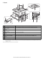
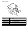
2. Internal
23
21 22
27
24
19
26
20
25
28
29
19 Toner cartridge lock release lever
To replace the toner cartridge, pull out the toner cartridge while pushing on this lever.
20 Toner cartridge
Contains toner.
21 Document feeder tray (when the SPF/
RSPF is installed)
Place the original(s) that you wish to scan face up here. Up to 40 sheets can be placed.
22 Original guides (when the SPF/RSPF is Adjust to the size of the originals.
installed)
23 Feeding roller cover (when the SPF/
RSPF is installed)
Open to remove misfeed originals.
24 Right side cover (when the SPF/RSPF is Open to remove misfeed originals.
installed)
25 Fusing unit release levers
To remove the paper misfeed in the fusing unit, push down on these levers and remove the paper.
26 Roller rotating knob
Rotate to remove misfeed paper.
27 Exit area (when the SPF/RSPF is
installed)
Originals exit the machine here after copying/scanning when the SPF/RSPF is used.
28 Photoconductive drum
Images are formed on the photoconductive drum.
29 Fusing unit paper guide
Open to remove misfeed paper.
Warning: The fusing unit is hot. Do not touch the fusing unit when removing misfeed paper. Doing so may cause a burn or injury.
Do not touch the photoconductive drum (green portion) when removing the misfeed paper. Doing so may damage the drum and cause
smudges on copies.
Note: The model name is on the front cover of the machine.
MX-M182 EXTERNAL VIEWS AND INTERNAL STRUCTURES 5-2
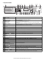
3. Operation Section
1
2 3
01
02
03
04
05
4
5
6
7
8 9
10 11
DEF
JKL
MNO
PQRS
TUV
WXYZ
FAX STATUS
COPY
SHIFT
06
07
08
09
10
11
12
13
14
15
REDIAL/PAUSE
PRINT
INTERRUPT
ABC
GHI
SPEAKER
12
ON LINE
DATA
BACK
OK
SPECIAL
FUNCTION
SCAN
SPEED
16
17
18
19
20
21
22
23
24
25
SYMBOL
FAX
COMM. SETTING
LINE
DATA
COPY EXPOSURE
SCAN COLOUR MODE
FAX PROGRAM
@.-_
PAPER SELECT COPY RATIO AUTO IMAGE OUTPUT 2-SIDED COPY
RESOLUTION ADDRESS FORMAT ORIGINAL SIZE DUPLEX SCAN
RESOLUTION ADDRESS BROADCAST ORIGINAL SIZE DUPLEX SCAN
ACC. #-C
READ-END
SPACE/–
13
14
15
16 17 18 19 20
21 22
23
24 25 26
1
Keys for fax function (when the fax
option is installed)
These are used in fax mode.
2
[COPY] key / indicator
Press to select copy mode. If pressed when "Ready to copy." appears or during warm-up, the total
number of sheets used appears while the key is pressed.
3
[PRINT] key / indicator
Press to select print mode.
• ONLINE indicator
Print jobs can be received when this indicator is lit.
• DATA indicator
This lights steadily when there is a print job in memory that has not been printed, and blinks
during printing.
4
[SCAN] key / indicator
Press to select scan mode. To use the machine as a network scanner, see the "Operation Guide
(NETWORK EXPANSION KIT)" that accompanies the machine.
5
[FAX STATUS] key (when the fax option
is installed)
This key is used in fax mode.
6
Display
Shows various messages.
7
[BACK] key
Press to return the display to the previous screen.
8
Copy number display
The selected number of copies appears. During copying, this shows the remaining number of
copies.
9
[OK] key
Press to enter the selected setting.
10 Numeric keys
Use to select the number of copies.
11 [C] key
Press to clear the set number of copies or stop a copy run.
12 [INTERRUPT] key (
indicator
) / INTERRUPT
Interrupts a copy run to allow an interrupt copy job to be performed.
13 [FAX] key / indicator (when the fax option This key is used in fax mode.
is installed)
LINE indicator, DATA indicator
14 [SPECIAL FUNCTION] key
Press to select special functions.
15 [EXPOSURE] key
Use to select the exposure mode. "AUTO", "TEXT", or "PHOTO" can be selected.
16 [PAPER SELECT] key
Use to manually select a paper tray.
17 [COPY RATIO] key
Press to select a reduction or enlargement copy ratio.
18 [AUTO IMAGE] key
Press to have the copy ratio selected automatically.
19 [OUTPUT] key
Use to select the sort function.
20 [2-SIDED COPY] key
(MX-M182D/MX-M202D/MX-M232D)
Select the two-sided copying mode.
21 Arrow keys
Press to move the highlighting (which indicates that an item is selected) in the display.
22 [ACC.#-C] key (
)
Press the end the use of an account and return the display to the account number entry screen.
23 [0] key
Press during a continuous copy run to display the number of copies completed.
24 [READ-END] key (
)
25 [CA] key
26 [START] key (
When copying in sort mode from the document glass, press this key when you have finished scanning
the original pages and are ready to start copying.
Clears all selected settings and returns the machine to the default settings.
) / indicator
Copying is possible when this indicator is on. Press the key to start copying. This indicator blinks when
auto power shut-off mode has activated. Press the key to return to normal operation.
MX-M182 EXTERNAL VIEWS AND INTERNAL STRUCTURES 5-3
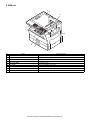
4. Motor, solenoid, clutch
13
1
12
2
3
11
4
6
5
7
8
10
No.
Name
Code
Function operation
1
Mirror motor
2
Toner motor
3
Duplex motor
DPX
Switchback operation and paper exit motor in duplex. (MX-M182D/M202D/M232D)
4
Main motor
MM
Drives the machine.
5
1st tray paper feed clutch
6
PS clutch
7
Bypass tray paper transport clutch
MPTC
Drives the bypass tray paper transport roller.
8
Bypass tray paper feed solenoid
MPFS
Bypass tray paper feed solenoid
9
2nd tray transport clutch
FSCL1
Drives the 2nd tray transport roller. (MX-M202D/M232D)
10 2nd tray paper feed clutch
PSCL2
Drives the 2nd tray paper feed roller. (MX-M202D/M232D)
11 Exhaust fan motor
PSFM
Cools the inside of the machine.
12 Cooling fan motor
VFM
Cools the inside of the machine.
13 Shifter motor
MRM
9
TM
CPSCL1
RRC
SFTM
Drives the optical mirror base (scanner unit).
Toner supply
Drives the pick up roller
Drives the resist roller
Drives the shifter motor.
MX-M182 EXTERNAL VIEWS AND INTERNAL STRUCTURES 5-4
5. Sensor, switch
1
17
20
3
(AB)
(AB)
(INCH)
19
18
4
(INCH)
16
15
5
6
2
7
14
13
8
9
12
No.
Name
Code
11
10
Function operation
1
Mirror home position sensor
MHPS
Detects the mirror (scanner unit) home position.
2
Side door switch
DSWR
Side door open detection
3
Paper exit sensor (paper exit side)
POD1
Detects paper exit.
4
Paper exit sensor (DUP side)
PDPX
Paper transport detection
5
Thermistor
RTH
6
Thermostat
RDTCT
7
Toner density sensor
8
2nd tray detection switch
CSD2
2nd tray detection
9
Bypass tray sensor
MPED
Bypass tray transport detection
10 2nd tray door open/close sensor
DRS2
2nd tray door open/close detection (MX-M202D/M232D)
11 2nd tray door paper pass sensor
PPD2
2nd tray paper entry detection (MX-M202D/M232D)
12 2nd tray paper empty sensor
CSS2
2nd tray paper empty detection (MX-M202D/M232D)
TCS
13 Paper in sensor
Fusing section temperature detection
Fusing section abnormally high temperature detection
Detects the toner density in the developing unit.
PIN
Paper transport detection
14 Tray empty
CSS1
Tray paper entry detection
15 Front cover SW
DSWF
Front cover open detection
16 Power switch
MAIN SW
Turns ON/OFF the main power source.
17 OC sensor
OCSW
Original cover and SPF open/close detection
18 Shifter home position sensor
SFTHP
Shifter home position detection
19 Original size sensor(Main Scaning)
DSIN0
Original size detection
20 Original size sensor(Sub Scaning)
DSIN1
Original size detection
MX-M182 EXTERNAL VIEWS AND INTERNAL STRUCTURES 5-5
6. PWB unit
2
1
8
3
7
9
4
6
5
No.
Name
Function operation
1
Copy lamp Inverter PWB
Copy lamp control
2
CCD sensor PWB
Image scanning
3
Main control PWB
Main control PWB
4
2nd tray PWB
2nd tray control
5
High voltage PWB
High voltage control
6
Power PWB
AC power input/DC power control
7
Operation main PWB
Operation panel input/Display, operation panel section control
8
USB I/F PWB
Connect a USB device
9
LCD OPE PWB
Display and operation panel control
MX-M182 EXTERNAL VIEWS AND INTERNAL STRUCTURES 5-6
7. Cross sectional view
1 2
3
4
56 7
18
8
9
10
11
12
13
14
15
23
22
21 20 19 17 16
No.
Name
Function/Operation
1
Copy lamp
Image radiation lamp
2
Copy lamp unit
Operates in synchronization with No. 2/3 mirror unit to radiate documents
sequentially.
3
LSU unit
Converts image signals into laser beams to write on the drum.
4
Lens unit
Reads images with the lens and the CCD.
5
MC holder unit
Supplies negative charges evenly on the drum.
6
Paper exit roller
Used to discharge paper.
7
Transport roller
Used to transport paper.
8
Upper heat roller
Fuses toner on paper (with the teflon roller).
9
Lower heat roller
Fuses toner on paper (with the silicon rubber roller).
10
Waste toner transport roller
Transports waste toner to the waste toner box.
11
Drum unit
Forms images.
12
Transfer charger unit
Transfer images (on the drum) onto paper.
13
DUP follower roller
Transports paper for duplex.
14
Duplex transport roller
Transports paper for duplex .
15
Resist roller
Takes synchronization between the paper lead edge and the image lead edge.
16
Bypass tray
Bypass tray
17
Bypass tray paper pick up roller
Picks up paper in bypass tray.
18
No. 2/3 mirror unit
Reflects the images from the copy lamp unit to the lens unit.
19
Bypass tray transport roller
Transports paper from the bypass tray.
20
2nd tray paper transport roller
Transports paper from the 2nd tray. (MX-M202D/M232D)
21
2nd tray paper pick up roller
Picks up paper from the 2nd tray. (MX-M202D/M232D)
22
1st tray paper feed roller
Picks up paper from the 1st tray.
23
MG roller
Puts toner on the OPC drum.
MX-M182 EXTERNAL VIEWS AND INTERNAL STRUCTURES 5-7
[6] ADJUSTMENTS
1. Adjustment item list
Section
A
B
Adjustment item
Process
section
Mechanism
section
Adjustment procedure/SIM No.
(1)
Developing doctor gap adjustment
Developing doctor gap adjustment
(2)
MG roller main pole position adjustment
MG roller main pole position adjustment
(3)
Developing bias voltage check
(4)
Main charger voltage check
(1)
Image position adjustment
SIM-50
(2)
Main scanning direction (FR direction) distortion balance
adjustment
No. 2/3 mirror base unit installing position adjustment
(3)
Main scanning direction (FR direction) distortion adjustment
Rail height adjustment
(4)
Sub scanning direction (scanning direction) distortion
adjustment
Winding pulley position adjustment
(5)
Main scanning direction (FR direction) magnification ratio
adjustment
SIM 48-1
(6)
Sub scanning direction (scanning direction) magnification ratio OC mode in copying (SIM 48-1)
adjustment
SPF mode in copying (SIM 48-5)
(7)
Off center adjustment
(1)
Copy mode
Copy lamp unit installing position adjustment
OC mode (SIM 50-12)
SPF mode (SIM 50-12)
C
Image density
adjustment
SIM 46-2
2. Copier adjustment
A. Process section
(2) MG roller main pole position adjustment
(1) Developing doctor gap adjustment
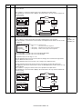
1) Remove the DV front cover, and put the developing tank on a flat
surface.
2) Tie a string to a needle or a pin.
3) Hold the string and bring the needle close to the MG roller
horizontally. (Do not use paper clip, which is too heavy to make a
correct adjustment.) (Put the developing unit horizontally for this
adjustment.)
4) Do not bring the needle into contact with the MG roller, but bring it to
a position 2 or 3mm apart from the MG roller. Mark the point on the
MG roller which is on the extension line from the needle tip.
5) Measure the distance from the marking position to the top of the
doctor plate of the developing unit to insure that it is 18mm.
If the distance is not within the specified range, loosen the fixing
screw A of the main pole adjustment plate, and move the adjustment
plate in the arrow direction to adjust.
1) Loosen the developing doctor fixing screw A.
2) Insert a thickness gauge of 1.5mm to the three positions at 20mm
and 150mm from the both ends of the developing doctor as shown.
20mm
150mm
20mm
A
1
A
DV front cover
3
A
2
3) Push the developing doctor in the arrow direction, and tighten the fixing
screws of the developing doctor in the sequence of 13233.
4) Check the clearance of the developing doctor. If it is within the
specified range, then fix the doctor fixing screw with screw lock.
* When inserting a thickness gauge, be careful not to scratch the
developing doctor and the MG roller.
<Adjustment specification>
Developing doctor gap
Both ends (20mm from the both ends) : 1.5 0.1mm
C (Center) (150mm from the both ends) : 1.5 0.1mm
MX-M182 ADJUSTMENT 6-1
(3) Developing bias voltage check
B. Mechanism section
Note: Use a digital multi-meter with an internal resistance of 10M or
more.
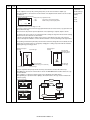
(1) Image position adjustment
1) Set the digital multi-meter range above 500 Vdc.
2) Put the test rod of the digital multi-meter on the developing bias
voltage output check pin.
3) Turn on the power, execute SIM25-1.
Note:In advance to this adjustment, the sub scanning magnification ratio
adjustment must be performed.
a. OC image lead edge position adjustment (SIM 50-1)
1) Set a scale on the OC table as shown below.
2) Make a copy.
3) Check the copy output. If necessary, perform the following
adjustment procedures.
4) Execute SIM 50-01.
Select a desired mode with the arrow keys, enter the adjustment
value with 10-key, and press [OK] key.
When [START] key is pressed, a sheet is printed.
(Mode selection window 1)
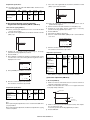
Sim50-1 LEAD EDGE
1:TRAY1
50
2:TRAY2
50
3:MFT
50
1/2 [
1- 99]
50
<Specification>
Mode
Specification
Developing bias voltage
DC - 400±10V
(Copy start window)
(4) Grid bias voltage check
Note: Use a digital multi-meter with an internal resistance of 10M or
more.
Ready to copy.
S
(Mode selection window 2)
Sim50-1 LEAD EDGE
4:DEN-A
50
5:RRC-A
1
6:DEN-B
50
2/2 [
1- 99]
50
(Copy execution window)
Copies in progress.
S
100%
100%
A4
1) Set the digital multi-meter range above 600 Vdc.
2) Put the test rod of the digital multi-meter on the grid bias voltage
output check pin.
3) Turn on the power.
(The voltage is outputted in the grid bias High output mode during
warming up, and in the grid bias Low output mode when warming up
is completed.)
A4
<Adjustment specification>
Adjustment
mode
SIM
Display
text array
OC image lead
edge position
SIM
50-1
RRC-A
R/0.1
Main cassette
print start
position
TRAY1
H/0.1
2nd cassette
print start
position
TRAY2
Multi bypass
tray print start
position
MFT
Lead edge void
DEN-A
Set
value
Spec
value
Lead edge
void:
1 - 4mm
Set
range
1 - 99
Image loss:
3mm or
less
B/0.05
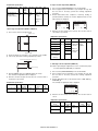
5) Set the OC lead edge position set value (RRC-A) to [1]
The OC image scanning start position is shifted inside the document
edge.
6) Set the main cassette lead edge void adjustment value (DEN-A)* to [1]
The lead edge void becomes the minimum.
<Specification>
Mode
Specification
Grid bias LOW
DC - 380±8V
Grid bias HIGH
DC - 525±10V
MX-M182 ADJUSTMENT 6-2
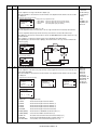
7) Set the main cassette print start position value (TRAY1) to [1] and
make a copy.
The print start position is shifted inside the document edge.
10) Set the lead edge void adjustment value (DEN-A)* again.
• 1 step of the set value corresponds to about 0.1mm shift.
• Calculate the set value from the formula below.
B/0.05 (mm) = Lead edge void adjustment value
<B: Lead edge void (mm)>
5mm
5
4mm
10
2.5mm
5
*The dimension varies depending on the model.
2.5mm
10
8) Measure the image loss R of the copied image. Enter the set value of
the image scanning lead edge position (RRC-A) again.
• 1 step of the set value corresponds to about 0.1mm shift.
• Calculate the set value from the formula below.
R/0.1(mm) = Image loss set value
<R: Image loss measurement value (mm)>
5mm
Example:
When setting the lead edge void to 2.5mm
:2.5 /0.05 = about 50
Note:If the set value is not obtained from the above formula, perform the
fine adjustment.
b. SPF image lead edge position adjustment (SIM50-6)
1) Set a scale on the OC table as shown below.
0mm
5
10
* The scanning edge is set.
(A line may be printed by scanning the document edge.)
Example:
4/0.1 = 40 = about 40
Note: If the set value is not obtained from the above formula, perform the
fine adjustment.
9) Measure the distance H between the paper lead edge and the image
print start position. Set the image print start position set value
(TRAY1) again.
• 1 step of the set value corresponds to about 0.1mm shift.
• Calculate the set value from the formula below.
H/0.1(mm) = Image print start position set value
<H: Print start position measurement value (mm)>
0mm
0mm
5
Note:Since the printed copy is used as a test chart, put the scale in
parallel with the edge lines.
2) Make a copy, Then use the copy output as an original to make an
SPF copy again.
3) Check the copy output. If necessary, perform the following
adjustment procedures.
4) Execute SIM 50-6.
5) Set the SPF lead edge position set value (SIDE1) so that the same
image is obtained as that obtained in the previous OC image lead
edge position adjustment.
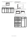
(Mode selection window)
Sim50-6 SPF EDGE
1:SIDE1
50
2:SIDE2
50
3:END EDGE
50
[
1- 99]
50
10
(Copy start window)
*Fit the print edge with the paper edge, and perform the
lead edge adjustment.
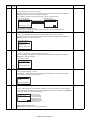
Example:
5/0.1 = 50 = about 50
Note: If the set value is not obtained from the above formula, perform the
fine adjustment.
Ready to copy.
S
100%
A4
MX-M182 ADJUSTMENT 6-3
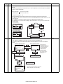
(Copy execution window)
Copies in progress.
S
100%
A4
<Adjustment specification>
Adjustment mode
SPF image lead
edge position
(1st print surface)
SIM
d. Paper off center adjustment (SIM50-10)
Display
text
array
SIM
50-6
Set value Spec value
SIDE1 1 step:
0.1mm
shift
Lead edge
void:
1 - 4mm
Set
range
1 - 99
Image loss:
3mm or
less
1) Set a test chart (UKOG-0089CSZZ) on the document table.
2) Select a paper feed port and make a copy. Compare the copy and
the test chart. If necessary, perform the following adjustment
procedure.
3) Execute SIM 50-10. After completion of warm-up, shading is
performed and the currently set off center adjustment value of each
paper feed port is displayed.
Sim50-10 PRT. CENTER
4:TRAY4
50
5:BYPASS
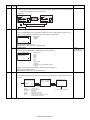
50
6:DUPLEX
50
2/2 [
1- 99]
50
Sim50-10 PRT. CENTER
1:TRAY1
50
2:TRAY2
50
3:TRAY3
50
1/2 [
1- 99]
50
c. Rear edge void adjustment (SIM50-1, SIM50-19)
4) Enter the set value and press the start key. The correction value is
stored and a copy is made.
1) Set a scale as shown in the figure below.
A4(8.5" x 11")
<Adjustment specification>
Adjustment
mod
SIM
Display
text array
Tray1
SIM
50-10
TRAY1
Tray2
Tray3
TRAY3
Tray4
2) Set the document size to A4 (8.5" x 11"), and make a copy at 100%.
3) If necessary, perform the following adjustment procedure.
Specification
Add 1:
Single:
0.1mm shift Center
to R side. ±2.0mm
Set
range
1 - 99
TRAY4 Reduce 1:
BYPASS 0.1mm shift
to L side.
DUPLEX
Manual paper
feed tray
Paper rear edge
TRAY2
Set value
Duplex
(Second print
surface)
Void amount (Standard value: 4mm or less)
e. Side edge void area adjustment (SIM26-43)
Scale image
Note:Before performing this adjustment, be sure to check that the paper
off center adjustment (SIM 50-10) is completed.
Paper rear edge
4) Execute SIM50-01 and select "DEN-B" with the arrow keys.
The currently set adjustment value is displayed.
5) Enter the set value and press the start key. The correction value is
stored and a copy is made.
<Adjustment specification>
Mode
SIM
Display
text array
Rear edge void
SIM
50-1
DEN-B
Set value
Specification
1 step:
4mm or
0.1mm shift less
1) Set a test chart (UKOG-0089CSZZ) on the document table.
2) Select a paper feed port and make a copy. Compare the copy and
the test chart. If necessary, perform the following adjustment
procedure.
3) Execute SIM 26-43 and set the density mode to SIDE VOID (L),
SIDE VOID (R).
The currently set adjustment value is displayed.
Set
range
Sim26-43 SIDE VOID
1:SIDE VOID(L)
3
2:SIDE VOID(R)
3
1 - 99
[
0- 10]
3
4) Enter the set value and press the start key. The correction value is
stored.
<Adjustment specification>
Adjustment
mode
SIM
Side void (left)
26-43
Side void (right)
MX-M182 ADJUSTMENT 6-4
Display
text array
Set value
Specification
SIDE
1 step:
0.5 - 4mm
VOID (L) 0.5mm shift
SIDE
VOID (R)
Set
range
1 - 99
(2) Main scanning direction (FR direction) distortion
balance adjustment
1) Remove the OC glass and the right cabinet.
(1)
(1)
(2)
4) Loosen the set screw of the scanner drive pulley which is not in
contact with No. 2/3 mirror base unit positioning plate.
5) Without moving the scanner drive pulley shaft, manually turn the
scanner drive pulley until the positioning plate is brought into contact
with No. 2/3 mirror base unit, then fix the scanner drive pulley.
(3)
(4)
(3)
2) Loosen the copy lamp unit wire fixing screw.
6) Put No. 2/3 mirror base unit on the positioning plate again, push the
projections on the front frame side and the rear frame side of the
copy lamp unit to the corner frame, and tighten the wire fixing screw.
Wire fixing screw
3) Manually turn the mirror base drive pulley and bring No. 2/3 mirror
base unit into contact with the positioning plate. At that time, if the
front frame side and the rear frame side of No. 2/3 mirror base unit
are brought into contact with the positioning plate at the same time,
the mirror base unit parallelism is proper. If one of them is in contact
with the positioning plate, perform the adjustment of 4).
MX-M182 ADJUSTMENT 6-5
(3) Main scanning direction (FR direction) distortion
adjustment
4) Loosen the mirror base drive pulley fixing screw on the front frame
side or on the rear frame side.
This adjustment must be performed in the following cases:
• When the mirror base drive wire is replaced.
• When the lamp unit, or No. 2/3 mirror holder is replaced.
• When a copy as shown is made.
When La < Lb
Turn the mirror base drive pulley on the front frame side in the
arrow direction A.
(Do not move the mirror base drive pulley shaft.)
When La > Lb
Turn the mirror base drive pulley on the rear frame side in the
arrow direction A.
(Do not move the mirror base drive pulley shaft.)
Lb
La
Rear side
A
Paper exit
direction
Copy
Original
B
1) Set A3 (11" x 17") white paper on the original table as shown below.
Front side
Allow a little space.
5) Tighten the mirror base drive pulley fixing screw.
<Adjustment specification>
La = Lb
Glass holding plate
A3 (11" x 17") white paper
Fit the paper edge and
the glass holding plate edge.
2) Open the original cover and make a normal (100%) copy.
3) Measure the width of the black background at the lead edge and at
the rear edge.
6) Execute the main scanning direction (FR) distortion balance
adjustment previously described in 2) again.
(4) Sub scanning direction (scanning direction) distortion
adjustment
When there is no skew copy in the mirror base scanning direction and
there is no horizontal error (right angle to the scanning direction), the
adjustment can be made by adjusting the No. 2/3 mirror base unit rail
height.
Before performing this adjustment, be sure to perform the horizontal
image distortion adjustment in the laser scanner section.
This adjustment must be performed in the following cases:
•When the mirror base wire is replaced.
•When the copy lamp unit or No. 2/3 mirror unit is replaced.
•When the mirror unit rail is replaced or moved.
•When a following copy is made.
Paper exit direction
La: Lead edge black background width
Lb: Rear edge black background width
Original
If the width (La) of the black background at the lead edge is equal that
(Lb) at the rear edge, there is no need to execute the following
procedures of 4) - 7).
MX-M182 ADJUSTMENT 6-6
Copy A
Copy B
1) Making of a test sheet
Make test sheet by drawing parallel lines at 10mm from the both
ends of A3 (11" x 17") white paper as shown below. (These lines
must be correctly parallel to each other.)
When La > Lb
Shift the mirror base B rail upward by the half of the
difference of La - Lb.
Parallel line
Parallel line
10mm
When La < Lb
Shift the mirror base B rail downward by the half of the
difference of Lb - La.
Example: When La = 12mm and Lb = 9mm, shift the mirror
base B rail upward by 1.5mm.
10mm
When Lc > Ld
Shift the mirror base B rail downward by the half of the
difference of Lc - Ld.
10mm
10mm
When Lc < Ld
Shift the mirror base B rail downward by the half of the
difference of Ld - Lc.
White paper
2) Make a normal (100%) copy of the test sheet on A3 (11" x 17")
paper. (Fit the paper edge with the glass holding plate edge.)
3) Measure the distances (La, Lb, Lc, Ld) at the four corners as shown
below.
La
When moving the mirror base rail, hold the mirror base rail
with your hand.
<Adjustment specification>
Lc
La = Lb, Lc = Ld
5) After completion of adjustment, manually turn the mirror base drive
pulley, scan the mirror base A and mirror base B fully, and check that
the mirror bases are not in contact with each other.
* If the mirror base rail is adjusted to extreme, the mirror base may
contact the frame or original glass. Be careful to avoid this.
Paper exit
direction
Lb
Ld
When La = Lb and Lc = Ld, no need to perform the procedures 4) and 5).
4) Move the mirror base F rail position up and down (in the arrow
direction) to adjust.
(5) Main scanning direction (FR direction) magnification
ratio adjustment (SIM 48-1)
Note:Before performing this adjustment, be sure to check that the CCD
unit is properly installed.
1) Put a scale on the original table as shown below.
2) Execute SIM 48-1.
3) After completion of warming up, shading is operated and the current
correction value of the main scanning direction magnification ratio is
displayed on the screen.
Sim48-1 COPY MAG.
1:F-R
50
2:SCAN
50
[
Note: Do not adjust the rail on the rear side.
If the rail on the rear side is adjusted, an error may occur.
Only the rail on the front side can be adjusted.
1- 99]
50
4) Enter the set values of the items of F and R, and press [START] key.
The correction values are saved and a copy is made.
MX-M182 ADJUSTMENT 6-7
<Adjustment specification>
Note: A judgment must be made with 200mm width, and must not be
made with 100mm width.
Adjustment mode
Main scanning
direction magnification ratio
SIM
Display
text array
48-1
F-R
Set
value
+1
+0.1%
-1
0.1%
Specifications
Set
range
Normal ±
1.0%
1 - 99
(6) Sub scanning direction (scanning direction)
magnification ratio adjustment (SIM 48-1, SIM 48-5)
a. OC mode in copying (SIM48-1)
Note: Before performing this adjustment, be sure to check that the CCD
unit is properly installed.
1) Put a scale on the original table as shown below, and make a normal
(100%) copy.
1) Put a scale on the original table as shown below, and make a normal
(100%) copy to make a test chart.
Note:Since the printed copy is used as a test chart, put the scale in
parallel with the edge lines.
2) Set the test chart on the SPF and make a normal (100%) copy.
3) Compare the scale image and the actual image. If necessary,
perform the following adjustment procedures.
4) Execute SIM 48-5.
5) After warm-up, shading is performed.
6) Check to confirm that the RSPF (SIDE1) mode is selected with the
cross cursor.
Sim48-5 (R)SPF ZOOM
1:RSPF(SIDE1)
50
2:RSPF(SIDE2)
50
[
1- 99]
50
7) Enter the set value and press the start key.
The set value is stored and a copy is made.
2) Compare the scale image and the actual image. If necessary,
perform the following adjustment procedures.
3) Execute SIM 48-1.
4) After completion of warming up, shading is operated and the current
correction value of the sub scanning direction magnification ratio is
displayed on the screen.
Sim48-1 COPY MAG.
1:F-R
50
2:SCAN
50
[
1- 99]
Sim48-1 COPY MAG.
1:F-R
50
2:SCAN
50
1- 99]
Adjustment mode
Sub scanning
direction
magnification
ratio
(Front surface)
SIM
48-5
Sub scanning
direction
magnification
ratio
(Back surface)
50
5) Select [2.SCAN] mode with the cross cursor.
[
<Adjustment specification>
Display
text array
Set
value
RSPF +1
(SIDE1) +0.1%
-1
0.1%
Specifications
Set
range
Normal ±
1.0%
1 - 99
RSPF
(SIDE2)
* "RSPF (SIDE2)" is displayed only when the RSPF is installed.
(7) Off center adjustment (SIM 50-12)
50
a. OC mode (SIM50-12)
6) Enter the set value and press the start key.
The set value is stored and a copy is made.
1) Make a test chart as shown below and set it so that its center line is
fit with the original guide center mark.
* To make a test chart, draw a line on A3 or 11" x 17" paper at the center
in the paper transport direction.
<Adjustment specification>
Adjustment mode
SIM
Sub scanning
48-1
direction
magnification ratio
OC mode
Display
text array
SCAN
Set
value
+1
+0.1%
-1
0.1%
Specifications
Set
range
Normal ±
1.0%
1 - 99
Original guide
Center
Copy paper
(A3 or 17" x 11")
b. RSPF sub scanning direction magnification ratio (SIM48-5)
Note:
•Before performing this adjustment, be sure to check that the CCD unit is
properly installed.
•Before performing this adjustment, the OC mode adjustment in copying
must be completed.
2) Make a normal copy from the manual paper feed tray, and compare
the copy and the test chart.
If necessary, perform the following adjustment procedures.
3) Execute SIM 50-12.
MX-M182 ADJUSTMENT 6-8
4) After completion of warming up, shading is performed and the
current off-center adjustment value is displayed on the LCD.
Sim50-12 ORG. CENTER
1:OC
50
2:SPF(SIDE1)
50
3:SPF(SIDE2)
50
[
1- 99]
50
C. Image density adjustment
(1) Copy mode (SIM 46-2)
1) Set a test chart (UKOG-0162FCZZ) on the OC table as shown
below.
5) Enter the set value and press the start key.
The set value is stored and a copy is made.
UKOG-0162FCZZ
<Adjustment specification>
Adjustment
mode
SIM
Document off- 50-12
center (OC
mode)
Display
text array
OC
Set value
Specifications
Set
range
+1
Shifted to R
side by
+0.mm.
-1
Shifted to L
side by
0.1mm.
Center ±
2.0%
1 - 99
2) Put several sheets of A3 or 11" x 17" white paper on the test chart.
3) Execute SIM 46-2.
4) After completion of warming up, shading is performed, and the
current density level is displayed on the LCD.
Sim46-1 EXP LEVEL
1:AE
50
2:TEXT
50
3:PHOTO 1
50
1/2 [
1- 99]
50
Sim46-1 EXP LEVEL
4:PHOTO 2
50
5:TEXT(TS)
50
6:AE(TS)
50
2/2 [
1- 99]
50
Use the cross cursor to select a mode.
5) Change the set value with the 10-key to adjust the copy image
density.
6) Make a copy and check that the specification below is satisfied.
<Adjustment specification>
Density Display Expomode
text
sure
array
level
Sharp Gray
Chart output
Automatic
AE
-
Text
TEXT
3
Photo
(Error
diffusion)
PHOTO
1
3
"2" is slightly The greater the set
copied.
value is, the darker
"3" is slightly the density is.
The smaller the set
copied.
value is, the lighter
"2" is slightly
the density is.
copied.
Photo
PHOTO
(Dither) 2
3
"2" is slightly
copied.
Toner
save
(Text)
TEXT
(TS)
3
"3" is slightly
copied.
Toner
save
(Automatic)
AE(TS)
-
"2" is slightly
copied.
MX-M182 ADJUSTMENT 6-9
Set value
Set
range
1 - 99
[7] SIMULATIONS
Main
code
22
1. Entering the simulation mode
Perform the following procedure to enter the simulation mode.
[#] key
[ ] key
[C] key
[ ] key
Main code
[START] key
Sub code
[START] key
2. Canceling the simulation mode
When the [CA] key is pressed, the simulation mode is cancelled.
When the interruption key is pressed, the process is interrupted and the
screen returns to the sub code entering display.
* After canceling the simulation mode, be sure to turn OFF/ON the
power and check the operation.
24
Note: If the machine is terminated by a jam error or paper empty during
copying in the adjustment by the simulation, recopying is required.
Note: The values in the simulation columns are not default values but
sample values.
3. List of simulations
Main
code
01
02
03
05
06
07
08
09
10
14
16
20
21
Sub
Contents
code
01 Mirror scanning operation
02 Mirror home position sensor (MHPS) status display
01 Single paper feeder (SPF)/Reversing single pass
feeder(RSPF) aging *2
02 SPF/RSPF sensor status display *2
03 SPF/RSPF motor operation check *2
08 SPF/RSPF paper feed solenoid operation check *2
09 RSPF reverse solenoid operation check *2 *3
11 SPF/RSPF PS release solenoid operation check *2
02 Shifter/job separator sensor status display
03 Shifter operation check
04 Job separator operation check *4
11 Shifter home position check
01 Operation panel display check
02 Fusing lamp and cooling fan operation check
03 Copy lamp lighting check
01 Paper feed/transport solenoid operation check
02 Resist roller solenoid (RRS) operation check
01 Warm-up display and aging with jam detection
06 Intermittent aging
08 Shifting with warm-up display
01 Developing bias output
02 Main charger output (Grid = HIGH)
03 Main charger output (Grid = LOW)
06 Transfer charger output
01 Duplex motor forward rotation check *6
02 Duplex motor reverse rotation check *6
04 Duplex motor RPM adjustment *6
05 Duplex motor switchback time adjustment
Toner motor operation
Trouble cancel (except for U2)
U2 trouble cancel
01 Maintenance counter clear
01 Maintenance cycle setting
25
Sub
code
01
03
04
07
09
11
13
14
15
22
01
02
04
05
06
07
08
09
10
13
14
15
01
02
26
30
41
10
01
02
03
04
05
06
07
08
18
20
22
30
31
36
37
39
42
43
51
54
56
60
69
73
74
01
01
02
03
04
42
01
MX-M182 SIMULATIONS 7-1
Contents
Counters display
Jam memory display
Jam total counter display
System setting code display
Paper feed counter display
FAX-related counter display
CRUM destination display *5
P-ROM version display
Trouble memory display
SPF/RSPF jam counter display *2
Jam total counter clear
Trouble memory clear
SPF/RSPF counter clear *2
Duplex print counter clear *6
Paper feed counter clear
Drum counter clear
Copy counter clear
Printer counter clear
FAX-related counter clear
Scanner counter clear
SPF/RSPF jam total counter clear *2
Scanner mode counter clear
Main motor operation check (Cooling fan motor rotation
check)
Auto developer adjustment (Initial setting of toner
density when replacing developer)
Polygon motor operation check
Job separator setting
Size setting
Auditor setting
Copier duplex setting
Count mode setting
Destination setting
Machine condition check
Manual transfer shaking countermeasures setting
Toner save mode setting
Job separator paper exit mode setting
Language setting clear
CE mark conformity control ON/OFF
Auditor mode exclusive setup
Cancel of stop at maintenance life over
Cancel of stop at developer life over
Memory capacity check
Transfer ON/OFF timing control setting
Side void amount setting
Copy temporary stop function setting
LCD contrast PWM duty setting
Life correction ON/OFF setting
[FAX] key Enable/Disable setting
Toner near end environment setting
Toner save setting display/non-display
Total counter display change setting
Paper sensor status display
Document size detection photo sensor check
Document size detection photo sensor detection level
adjustment
Document size detection photo sensor light receiving/
detection level check
Detection level adjustment when the document size is
settled(15degrees - 20degrees)
Developing counter clear
Main
code
43
44
46
48
49
50
51
53
61
63
64
65
Sub
code
01
02
03
04
12
13
01
Contents
Fusing temperature setting 1
Fusing temperature setting 2
Fusing temperature setting 3
Fusing temperature setting 4
Standby mode fusing fan rotation setting
Paper interval control allow/inhibit setting
Enable/Disable setting of toner density control
correction
16 Toner density control data check and toner density
correction quantity display
34 Transfer current setting
02 Copy density adjustment (600dpi)
10 Copy exposure level adjustment, individual setting
(Text) 600dpi
11 Copy exposure level adjustment, individual setting
(Photo) 600dpi
12 Density adjustment in the FAX mode
(Collective adjustments)
13-16 Density adjustment in the FAX mode
(Individual adjustments)
19 Exposure mode setting
(Gamma table setting/AE operation mode setting/
Photo image process setting)
20 SPF/RSPF exposure correction *2
29 Image contrast adjustment (600dpi)
30 AE limit setting
31 Image sharpness adjustment
39 FAX IMAGE adjustment
01 Main/sub scanning magnification ratio adjustment
05 SPF/RSPF mode sub scanning magnification ratio
adjustment in copying *2
08 FAX magnification ratio adjustment (scan)
09 FAX magnification ratio adjustment (print)
01 Flash ROM program writing mode (MCU)
02 Flash ROM program writing mode (NNB)
01 Image lead edge adjustment
06 Copy lead edge position adjustment (SPF/RSPF) *2
8
FAX lead edge adjustment (scan)
10 Print off-center adjustment
12 Document off-center adjustment
18 Memory reverse position adjustment in duplex copy *1
19 Rear edge void adjustment in duplex copy *5
02 Resist amount adjustment
08 SPF/RSPF scanning position automatic adjustment *2
02 Laser power correction ON/OFF (Invalidity)
03 HSYNC output check
01 Shading check
01 Self print
10 Key ACK time setting display/non-display setting
11 Info lamp setting
Main
code
66
67
Sub
code
01
02
03
04
06
07
10
11
13
17
21
24
30
31
32
33
34
37
38
42
43
52
50
Contents
FAX soft SW setting
FAX soft SW initializing
FAX PWB memory check
Signal send mode
Confidential pass code print
Image memory content output
Image memory contents clear
300bps signal send
Dial number registration
DTMF signal send
FAX information print
FAST SRAM clear
TEL/LIU status change check
TEL/LIU setting
Receive data check
Signal detection check
Communication time measurement
Speaker sound volume adjustment
Time setting/check
PC program writing
PIC adjustment value writing
Pseudo ringer check
USB reception speed adjustment
<Execution inhibit conditions>
*1) Execution is inhibited when the duplex setup is OFF and other than
RSPF is set.
*2) Execution is inhibited when OC.
*3) Execution is inhibited when SPF. (Not RSPF)
*4) Execution is inhibited when the job separator is not installed.
*5) Execution is inhibited when the model is not provided with the
CRUM.
*6) Execution is inhibited when the duplex setup is OFF.
MX-M182 SIMULATIONS 7-2
4. Contents of simulations
Main
code
Sub
code
01
01
Contents
Mirror scanning operation
Used to check the operations of the scanner unit and its control circuit.
Enter the number of times and the magnification ratio, and press [OK] key to operate the scanner unit. The
speed is variable according to the specified magnification ratio. The number of scanning can be specified by
entering a value to the right lower section of the LCD.
•Setting range of magnification ratio: 25%-400%
•Setting range of the number of scanning: 0-999 (When 0 is set, it means unlimited. )
(Scan number input window)
Sim1-1 SCAN CHECK
MHPS
115%
100%
86%
123
ZOOM 100%
5
Set the scan magnification ration.
This magnification ratio accords with the scan speed
in actual copying. The setting range is 25% - 400%.
Specify the scan number to be performed.
The setting range is 0 - 999. When 0 is set,
the number is unlimited.
[OK] key or [START] Key
(Execution
window)
Sim1-1 SCAN CHECK
MHPS
115%
100%
86%
123
ZOOM 100% EXEC
MHPS sensor status
Scan counter
Highlighted during execution
Used to display the status (ON/OFF) of the mirror HP sensor on the LCD during scanning. (Highlighted at
ON)
"EXEC" is displayed to indicate execution is in process. The scan counter is displayed above "EXEC." This
counter is counted up even in simulation.
The copy lamp is lighted during scanning.
[CA] key: Exits the simulation mode.
[INTERRUPT] key: Returns to the sub code input window.
[C] key: Input value clear
Numeric keys: Input of the number of scanning
02
Mirror home positions sensor (MHPS) status display
Used to monitor the mirror home position sensor and display the ON/OF status of the sensor on the LCD.
Sim1-2 SENSOR CHECK
MHPS
MHPS(MIRROR HOME POSITION SENSOR)
ON
:Highlight display
OFF :Normal display
[CA] key: Exits the simulation mode.
[INTERRUPT] key: Returns to the sub code input window.
MX-M182 SIMULATIONS 7-3
Remark
Main
code
Sub
code
02
01
Contents
Remark
Single Paper Feeder(SPF)/Reversing single pass feeder(RSPF)aging
Used to check the operations of the SPF/RSPF unit and its control circuit.
Enter the magnification ratio and press[OK] key or [START] key to drive the SPF/RSPF unit at the speed
corresponding to the setting.
(Magnification ratio selection window)
Select the scan magnification ratio (drive speed).
Sim2-1 SPF AGING
This also accords with the magnification ratio and
115%
1SIDE
the speed in copying similarly to the OC.
100%
2SIDE
The setting range is 50% - 200%.
86%
ZOOM
100%
EXEC
[OK] key or [START] Key
(Execution
window)
Sim2-1 SPF AGING
115%
1SIDE
100%
2SIDE
86%
ZOOM 100% EXEC
*
*
02
"EXEC" is highlighted during execution.
When [INTERRUPT] key is press, the simulation is terminated and the machine returns to the sub code
input window.
When [CA] key is pressed, the simulation is terminated and the machine exits the simulation mode.
SPF/RSPF sensor status display
Only when the SPF/
RSPF is installed.
Used to display the sensor status in the SPF/RSPF section. An active sensor is highlighted.
Sim2-2 SENSOR CHECK
SPFP
L1
W2
OCCV
L2
W3
POUT
W0
SPFC
W1
Displayed name
: Sensor name
SPFP
:SPF document transportation sensor
OCCV
:SPF unit (OC cover) open/close sensor
POUT
:SPF paper exit sensor
SPFC
:SPF paper feed cover open/close sensor
L1
:SPF paper length sensor 1
L2
:SPF paper length sensor 2
W0
:SPF document set sensor
W1
:SPF paper width sensor (small)
W2
:SPF paper width sensor (middle)
W3
:SPF paper width sensor (large)
[CA] key: Exits the simulation mode.
[INTERRUPT] key: Returns to the sub code input window.
03
SPF/RSPF motor operation check
Only when the SPF/
RSPF is installed.
Used to check the operation of the SPF/RSPF motor and its control circuit. When this simulation is
executed, the initial menu shown below is displayed. Select the magnification ratio to drive the motor.
(Initial window = Magnification ratio selection window)
Select the scan magnification ratio (drive speed).
Sim2-3 OUTPUT CHECK
This also accords with the magnification ratio and
115%
the speed in copying.
100%
The setting range is 50% - 200%.
86%
ZOOM
100%
EXEC
[OK] key or [START] Key
(Execution
window)
Sim2-3 OUTPUT CHECK
115%
100%
86%
ZOOM 100% EXEC
"EXEC" is highlighted during execution.
[CA] key: The SPF/RSPF motor is stopped, and the machine exits the simulation mode.
[INTERRUPT] key: The SPF/RSPF motor is stopped, and the machine returns to the sub code input window.
MX-M182 SIMULATIONS 7-4
Main
code
Sub
code
02
08
Contents
Remark
SPF/RSPF paper feed solenoid operation check
Used to drive the SPF/RSPF paper feed solenoid (PSOL) 20 times in the cycle of 500msec of "ON" and
500msec of "OFF." After completion of the process, the machine returns to the sub code input window.
(Initial window)
Sim2-8 SPUS CHECK
(Only when the
SPF/RSPF is
installed.}
(Execution window)
Sim2-8 SPUS CHECK
[OK] key or [START] Key
PRESS OK KEY EXEC
EXEC
When [INTERRUPT] key is pressed, the machine returns to the sub code input window.
When [CA] key is pressed, the machine exits the simulation mode.
09
RSPF reverse solenoid operation check
(Only when the
RSPF is installed.)
Used to drive the RSPF reverse solenoid (RSOL) 20 times in the cycle of 500msec of "ON" and 500msec of
"OFF." After completion of the process, the machine returns to the sub code input window.
(Initial window)
Sim2-9 SPFS CHECK
(Execution window)
Sim2-9 SPFS CHECK
[OK] key or [START] Key
PRESS OK KEY EXEC
EXEC
When [INTERRUPT] key is pressed, the machine returns to the sub code input window.
When [CA] key is pressed, the machine exits the simulation mode.
11
SPF/RSPF PS release solenoid operation check
Used to drive the SPF/RSPF PS release solenoid (CLH) 20 times in the cycle of 500msec of "ON" and
500msec of "OFF." After completion of the process, the machine returns to the sub code input window.
(Initial window)
Sim2-11 CLH CHECK
(Only when the
SPF/RSPF is
installed.)
(Execution window)
Sim2-11 CLH CHECK
[OK] key or [START] Key
PRESS OK KEY EXEC
EXEC
When [INTERRUPT] key is pressed, the machine returns to the sub code input window.
When [CA] key is pressed, the machine exits the simulation mode.
03
02
Shifter/job separator sensor status display
(Sensor of shifter is
Japan only)
Used to monitor the sensors related to the shifter and the job separator and display the sensor status on the (Only when the job
LCD. An active sensor is highlighted.
separator is
installed.)
Sim3-2 SENSOR
SFTHP JSUP JSDL
TRYF
TRYD
*
Displayed name
SFTHP
JSUP
JSDL
TRYF
TRYD
:Sensor name
:Shifter home position sensor
:Job separator upper limit sensor
:Job separator lower limit sensor
:Tray full sensor
: Paper exit sensor
Displayed only when the job separator is installed except for SFTH.
MX-M182 SIMULATIONS 7-5
Main
code
Sub
code
03
03
Contents
Remark
Shifter operation check
Japan only
Used to reciprocate the shifter 4 times.
During execution, the status of the shifter HP sensor is displayed on the right upper section of the screen.
(When the sensor is detected, the display is highlighted.)
[CA] key: Exits the simulation mode.
[INTERRUPT] key: Returns to the sub code input window.
* When the above [CA] key or [INTERRUPT] key is pressed during operation of the shifter, the shifter is
returned to the home position before terminating the operations.
(Initial window)
Sim3-3 SHIFTER CHK
(Execution window)
Sim3-3 SHIFTER CHK
[OK] key or [START] Key
PRESS OK KEY EXEC
04
SFTHP
EXEC
Job separator operation check
Used to operate the job separator up and down for 30sec.
During operation, the status of the upper limit sensor and the lower limit sensor is displayed on the right
upper section of the display.
(Only when the job
separator is
installed.)
[CA] key: Exits the simulation mode.
[INTERRUPT] key: Returns to the sub code input window.
When the operation is interrupted, the job separator is shifted to the home position before terminating the
simulation similarly to the shifter.
(Initial window)
Sim3-4 JOBSEPA CHK
(Execution window)
Sim3-4 JOBSEPA CHK
[OK] key or [START] Key
JSUP
JSDL
PRESS OK KEY EXEC
11
EXEC
Display
name
Sensor
name
JSUP
Job separator
upper limit sensor
JSDL
Job separator
lower limit sensor
Shifter home position check
Japan only
Used to check the operations of the shifter HP sensor and the shifter. When this simulation is executed, the
initial menu is displayed. By the following key operations, the left operation and the right operation of the
home position sensor and the shifter can be executed separately.
[ ] key: Shifts to R side by the specified steps.
[ ] key: Shifts to F side by the specified steps.
[ ] key: Shift to the home position.
[SFTHP] is highlighted when the HP sensor is detected.
(Initial window)
Sim3-11 SHIFTER CHK
SFTHP
[
]:R [
]:HP [
]:F
[CA] key: Exits the simulation mode.
[INTERRUPT] key: Returns to the sub code input window.
MX-M182 SIMULATIONS 7-6
Main
code
Sub
code
05
01
Contents
Remark
Operation panel display check
<LED/LCD check mode>
Used to check the operations (ON, display) of the LED and the LCD on the operation panel.
When this simulation is executed, all LED's on the operation panel (including 7SEG) are lighted and
checking LCD is started.
For the operation check of LCD, the area is divided into two sections; upper section and lower section, and
Dark
Light
Off is repeated in each section. Each display period is
the display cycle of Normal
2sec.
Normal
Dark
Sim5-1 LCD/LED CHK.
Normal
Sim5-1 LCD/LED CHK.
Dark
Sim5-1 LCD/LED CHK.
Sim5-1 LCD/LED CHK.
Light
Sim5-1 LCD/LED CHK.
Light
Sim5-1 LCD/LED CHK.
Off
Sim5-1 LCD/LED CHK.
Sub code input standby window
When [INTERRUPT] key is pressed in the LED check mode, the machine returns to the sub code input
window.
When [CA] key is pressed, the machine exits the simulation mode.
When [START] key is pressed during LCD display, the machine goes to the key input check mode.
<Key input check mode>
Used to check that the keys on the operation panel are properly detected.
When the machine enters the key input check mode, the initial menu is displayed.
(Initial window)
Sim5-1 LCD/LED CHK.
0
When any key is pressed, the value on the right lower side is counted up.
If a key is pressed once, it is not counted again.
When [CA] key is pressed for the first time, it is counted. When it is pressed for the second time, the
simulation mode is terminated.
When [INTERRUPT] key is pressed for the first time, it is counted. When it is pressed for the second time,
the window returns to the sub code input standby window.
* Note for the key input check mode
[START] key must be pressed at the end. If it is pressed midway, the simulation judges that the last key
is pressed and terminates the check mode. Multi input of tow or more keys is ignored.
MX-M182 SIMULATIONS 7-7
Main
code
Sub
code
05
02
Contents
Remark
Fusing lamp and cooling fan operation check
Used to check the operations of the heater lamp and the cooling fan and the peripheral circuits.
When this simulation is executed, the following initial menu is displayed.
(Initial window)
Sim5-2
HT LAMP
(Execution window)
Sim5-2
HT LAMP
[OK] key or [START] Key
PRESS OK KEY EXEC
EXEC
When this simulation is executed, the fusing lamp repeats ON/OFF 5 times in the cycle of 500ms.
The cooling fan motor is rotated during that period. (The cooling fan, however, is rotated for about 8sec.)
After completion of the operation, the machine returns to the sub code input window.
03
Copy lamp lighting check
Used to check the operations of the copy lamp and its peripheral circuit.
When this simulation is executed, the following initial menu is displayed.
(Initial window)
Sim5-3 COPY LAMP
(Execution window)
Sim5-3 COPY LAMP
[OK] key or [START] Key
EXEC
PRESS OK KEY EXEC
When [OK] key or [START] key is pressed, the copy lamp is lighted for about 5sec.
After passing for 5sec, the machine returns to the sub code input window.
06
01
Paper feed/transport solenoid operation check
When this simulation is executed, the names of the solenoids which can be operated are displayed. Select a
load to be operated with the numeric keys.
(Load selection window)
Sim6-1 OUTPUT CHECK
1:CPSOL 4:PSOL3
2:PSOL1 5:HPSOL
3:PSOL2 6:FSOL2
1/2
EXEC
1
Numeric keys
(Load selection window)
Sim6-1 OUTPUT CHECK
1:CPSOL 4:PSOL3
2:PSOL1 5:HPSOL
3:PSOL2 6:FSOL2
1/2
EXEC
2
1: CPSOL :Cassette 1 paper feed solenoid
2: PSOL1
:Cassette 2 paper feed solenoid (*)
3: PSOL2
:Cassette 2 paper feed solenoid (*)
4: PSOL3
:Cassette 3 paper feed solenoid (*)
5: HPSOL :Manual feed tray paper feed solenoid
6: FSOL2
:Cassette 2 transport solenoid (*)
7: FSOL3
:Cassette 3 transport solenoid (*)
(*) Supported only for the model with the option installed.
Skipped for the other models without installation.
After completion
of execution
[OK] key or [START] Key
(Execution window)
Sim6-1 OUTPUT CHECK
1:CPSOL 4:PSOL3
2:PSOL1 5:HPSOL
3:PSOL2 6:FSOL2
1/2
EXEC
2
02
During execution, the selected solenoid repeats
ON/OFF 20 times for every 500ms.
Resist roller solenoid (RRS) operation check
When this simulation is executed, the machine goes to the execution start window. When [OK] key or
[START] key is pressed, the resist roller solenoid (RRS) repeats ON of 500ms and OFF of 500ms 20 times.
(Execution start window)
Sim6-2 RRS CHECK
(Execution window)
Sim6-2 RRS CHECK
[OK] key or [START] Key
PRESS OK KEY EXEC
EXEC
When the operation is completed, the machine returns to the sub code input window.
When [INTERRUPT] key is pressed, the machine returns to the sub code input window. When [CA] key is
pressed, the machine exits the simulation mode.
MX-M182 SIMULATIONS 7-8
Main
code
Sub
code
07
01
Contents
Remark
Warm-up display and aging with jam detection
Used to measure the warm-up time and execute aging with jam detection.
When this simulation is executed, the following warm-up window is displayed.
The time required for starting the warm-up and completing the initializing operation and shifting to the standby state is displayed.
After completion of warm-up, press [CA] key to exit the simulation mode, allowing normal copy operations.
The copy mode at that time is the aging mode with 0sec of intermittent aging.
(Warming up completion window)
Sim7-1 W-UP C-MODE
[CA] key
WARM UP COMPLETED.
(Warming up window)
Sim7-1 W-UP C-MODE
WARMING UP.
(Copy window)
Ready to copy.
S
100%
1
10
8 1/2×11
Canceled by turning off the power or executing a simulation which makes the hardware reset. When the
interruption is pressed to shift to the input standby window, the machine does not enter the aging mode.
06
Intermittent aging
Used to execute intermittent aging of 3sec. The set quantity and the mode are optionally selected.
When this simulation is executed, the following execution start window is displayed.
When [OK] key or [START] key is pressed, the machine exits the simulation mode.
Enter a desired coy mode and a desired copy quantity.
Press [START] key, and intermittent aging will be started.
(Copy window)
Ready to copy.
S
(Execution start window)
Sim7-6 INTERVAL SET
AGING INTERVAL
100%
AER YOU SURE? EXEC
8 1/2×11
It is canceled by turning off the power or executing a simulation with the hard reset.
08
Shifting with warm-up display
Used to measure the warm-up time.
When this simulation is executed, the following warm-up window is displayed.
The time required for starting the warm-up and completing the initializing operation and shifting to the standby state is displayed.
* Though [CA] key is pressed, the machine does not enter the aging mode of intermission 0 sec.
(Warming up window)
Sim7-8 W-UP C-MODE
WARMING UP.
(Warming up completion window)
Sim7-8 W-UP C-MODE
WARM UP COMPLETED.
1
10
Press [CA] key to exit the simulation mode.
(The aging function is omitted from SIM 07-01.)
Note: Toner supply operation is not performed during this simulation.
08
01
Developing bias output
Used to check the developing bias output.
When this simulation is executed, the following execution start window is displayed.
When [OK] key or [START] key is pressed, the developing bias signal is turned ON for 30sec. When
measuring the actual output value, however, use SIM 25-01.
After completion of the process, the machine returns to the sub code input window.
(Execution start window)
Sim8-1 DV BIAS
(Execution window)
Sim8-1 DV BIAS
[OK] key or [START] Key
PRESS OK KEY EXEC
EXEC
[CA] key: Exits the simulation mode.
[INTERRUPT] key: Interrupts output operation and shifts to the sib code input window.
MX-M182 SIMULATIONS 7-9
Main
code
Sub
code
08
02
Contents
Remark
Main charger output (Grid = HIGH)
Used to check the main charger output.
When this simulation is executed, the following execution start window is displayed.
When [OK] key or [START] key is pressed, the main charger is turned on for 30 sec in the grid voltage HIGH
mode.
After completion of the process, the machine returns to the sub code input window.
(Execution start window)
Sim8-2 MHV(H)
(Execution window)
Sim8-2 MHV(H)
[OK] key or [START] Key
PRESS OK KEY EXEC
EXEC
[CA] key: Exits the simulation mode.
[INTERRUPT] key: Interrupts output operation and shifts to the sub code input window.
03
Main charger output (Grid = LOW)
Used to check the main charger output.
When this simulation is executed, the following execution start window is displayed.
When [OK] key or [START] key is pressed, the main charger is turned on for 30 sec in the grid voltage LOW
mode.
After completion of the process, the machine returns to the sub code input window.
(Execution start window)
Sim8-3 MHV(L)
(Execution window)
Sim8-3 MHV(L)
[OK] key or [START] Key
PRESS OK KEY EXEC
EXEC
[CA] key: Exits the simulation mode.
[INTERRUPT] key: Interrupts output operation and shifts to the sub code input window.
06
Transfer charger output
When this simulation is executed, the machine shifts to the following mode select window, and the list of the
modes to be outputted is displayed.
Select an output mode with numeric keys and press [OK] key or [START] key, and the transfer charger
output is made for about 30sec in the specified mode.
(Mode selection window)
Sim8-6 TC OUTPUT
1:NML_A 4:SML_B
2:NML_B 5:BYPASS
3:SML_A
EXEC
2
(Execution window)
Sim8-6 TC OUTPUT
[OK] key or [START] Key
1:NML_A 4:SML_B
2:NML_B 5:BYPASS
3:SML_A
EXEC
2
Window display
Output mode
1:NML_A
Normal size width (front)
2:NML_B
Normal size width (back)
3:SML_A
Small size width (front)
4:SML_B
Small size width (back)
*
*
The items of (back) is not displayed when DUPLEX setting is OFF.
Small size paper is Letter R (A4R) width or below. When an output is completed, the machine shifts to
the mode select window.
[CA] key: Exits the simulation mode.
[INTERRUPT] key: Interrupts the output operation, and shifts to the sub code input window.
MX-M182 SIMULATIONS 7-10
Main
code
Sub
code
09
01
Contents
Remark
Duplex motor forward rotation check
Used to check the duplex motor rotation.
The duplex motor is rotated in the normal direction (paper exit direction) for 30sec.
After completion of the process, the machine shifts to the sub code input window.
(Execution start window)
Sim9-1 DMF CHECK
(Execution is not
allowed when
DUPLEX setting is
OFF.)
(Execution window)
Sim9-1 DMF CHECK
[OK] key or [START] Key
PRESS OK KEY EXEC
EXEC
[CA] key: Exits the simulation mode.
[INTERRUPT] key: Interrupts the output operation, and shifts to the sub code input window.
02
Duplex motor reverse rotation check
Used to check the duplex motor reverse rotation.
The duplex motor is rotated in the reverse direction for 30sec.
After completion of the process, the machine shifts to the sub code input window.
(Execution start window)
Sim9-2 DMR CHECK
(Execution is not
allowed when
DUPLEX setting is
OFF.)
(Execution window)
Sim9-2 DMR CHECK
[OK] key or [START] Key
PRESS OK KEY EXEC
EXEC
[CA] key: Exits the simulation mode.
[INTERRUPT] key: Interrupts the output operation, and shifts to the sub code input window.
04
Duplex motor RPM adjustment
Default:
4
Used to adjust the duplex motor rotation speed.
When this simulation is executed, the following setting window is displayed. Enter an input value with
numeric keys and press [OK] key or [START] key.
The setting range is in 1-13 steps.
(Setting window)
Sim9-4 MOTOR SPEED
1:MOTOR SPEED
[
1-13]
4
4
• 18cpm/20cpm machine:
• 23cpm machine:
Set value : Speed (PPS)
Set value : Speed (PPS)
01
: 637.2PPS (Slow)
01
: 760.2PPS (Slow)
02
: 640.4PPS
02
: 764.1PPS
03
: 643.6PPS
03
: 768.0PPS
04
: 646.9PPS
04
: 771.8PPS
05
: 650.1PPS
05
: 775.7PPS
06
: 653.3PPS
06
: 779.5PPS
07
: 656.5PPS
07
: 783.3PPS
08
: 659.8PPS
08
: 787.2PPS
09
: 662.9PPS
09
: 791.0PPS
10
: 666.2PPS
10
: 794.8PPS
11
: 669.4PPS
11
: 798.6PPS
12
: 672.6PPS
12
: 802.5PPS
When a value outside the setting range is inputted, it is ignored.
[CA] key: Exits the simulation mode.
[INTERRUPT] key: Shift to the sub code input window.
05
Duplex motor switchback time adjustment
Used to adjust the duplex motor switchback time when the motor reverse rotation is controlled.
When this simulation is executed, the following setting window is displayed. Enter an input value with
numeric keys and press [OK] key or [START] key.
The setting range is 50-76.
When the adjustment value is increased by 1, the distance up to reverse start is increased by 3 steps in 1-2
phase excitement.
Sim9-5 SW BACK TIME
1:SW BACK TIME
[ 50-76]
50
50
When a value outside the setting range is inputted, it is ignored.
[CA] key: Exits the simulation mode.
[INTERRUPT] key: Shift to the sub code input window.
MX-M182 SIMULATIONS 7-11
Default:
50
Main
code
Sub
code
10
-
Contents
Remark
Toner motor operation
Used to check the operation of the toner motor.
When this simulation is executed, the following execution start window is displayed. Press [OK] key or
[START] key, and the toner motor is rotated for about 30sec.
After completion of the process, the machine shifts to the sub code input window.
(Execution start window)
Sim10 TONER MOTOR
(Execution window)
Sim10 TONER MOTOR
[OK] key or [START] Key
PRESS OK KEY EXEC
EXEC
[CA] key: Exits the simulation mode.
[INTERRUPT] key: Interrupts the output operation, and shifts to the sub code input window.
14
-
Trouble cancel (except for U2)
* Used to cancel EEPROM writing troubles such as H trouble and execute the hard reset.
When this simulation is executed, the following execution start window is displayed. Press [OK] key or
[START] key to clear the trouble other than U2.
(Execution start window)
Sim14 TROUBLE CLEAR
TROUBLE CLEAR
(WITHOUT U2)
AER YOU SURE? EXEC
16
-
U2 trouble cancel
* Used to cancel the U2 trouble and execute the hard reset.
When this simulation is executed, the following execution start window is displayed. Press [OK] key or
[START] key to clear the U2 trouble.
(Execution start window)
Sim16 TROUBLE CLEAR
U2 TROUBLE CLEAR
AER YOU SURE? EXEC
20
01
Maintenance counter clear
Used to clear the maintenance counter.
Press [OK] key or [START] key on the following window, the maintenance counter is cleared and the
machine returns to the sub code input window.
Sim20-1 COUNTER CLR
MAINTENANCE COUNTER
CLEAR
AER YOU SURE? EXEC
21
01
Maintenance cycle setting
Default:
4
Used to set the maintenance cycle. When this simulation is executed, the current set value is displayed.
Enter a desired code with numeric keys and press [START] key. The set value is saved in the EEPROM and
the machine returns to the sub code input window.
Sim21-1 CYCLE SET.
1:MAINTE CYCLE
[
0- 5]
4
4
0: 5K (5,000 sheets)
1: 7.5K (7,500 sheets)
2: 10K (10,000 sheets)
3: 25K (25,000 sheets)
4: 50K (50,000 sheets)
5: FREE (999,999 sheets)
(Setting range: 0 - 5)
[CA] key: Exits the simulation mode.
[INTERRUPT] key: Returns to the sub code input window.
MX-M182 SIMULATIONS 7-12
Main
code
Sub
code
22
01
Contents
Counters display
Sim22-1 COUNTER 1/4
TOTAL
:nnnnnnn
MAINTE :nnnnnnn
DEV
:nnnnnnn(*)
DRUM
:nnnnnnn
key
key
Sim22-1 COUNTER 2/4
CPY JOB : nnnnnnn
PRT JOB : nnnnnnn
SCN JOB : nnnnnnn
OC SCN : nnnnnnn
key
key
Sim22-1 COUNTER 3/4
SPF
: nnnnnnn
DUPLEX : nnnnnnn
OTHERS : nnnnnnn
MNTCYC : nnnnnnn
key
Counter display
TOTAL
: Total counter
MAINTE : Maintenance counter
DEV
: Development counter
DRUM
: Drum counter
CPY JOB : Copy job counter
PRT JOB : Print job counter
SCN JOB : Scan job counter
OC SCN : OC scan counter
SPF
: SPF/RSPF counter
DUPLEX : DUPLEX counter
OTHERS : Other counter
MNTCYC : Maintenance cycle
DEV TTL : Development rotation accumulated time
DRM TTL : Drum rotation accumulated time
key
Sim22-1 COUNTER 4/4
DEV TTL : nnnnnnn
DRM TTL : nnnnnnn
Though SIM26-74 is set to "1: Scan counter is added," the count is not added to SIM22-01 total counter
display. The setting affects only the total counter display in the system settings.
03
Jam memory display
Used to check the jam kind occurred in the main unit and the SPF/RSPF.
The kinds of jams up to 30 items are displayed sequentially from the latest one. (The oldest one is deleted
sequentially.) This display is used for troubleshooting. (If there are extremely many troubles in a position, it
may be judged that a repair must be executed.)
The kinds and contents of jams to be displayed are as follows.
Sim22-3 JAM HIS. 1/4
XXXXXXX
XXXXXXX
XXXXXXX
XXXXXXX
XXXXXXX
XXXXXXX
XXXXXXX
XXXXXXX
key
key
Sim22-3 JAM HIS. 2/4
XXXXXXX
XXXXXXX
XXXXXXX
XXXXXXX
XXXXXXX
XXXXXXX
XXXXXXX
XXXXXXX
Kinds of jams and display contents
SPPD_ON : SPF paper entry sensor (Not reached)
SPPD_OFF : SPF paper entry sensor (Remaining)
SOUT_ON : SPF paper exit sensor (Not reached)
SOUT_OFF : SPF paper exit sensor (Remaining)
POUT_ON : Paper exit sensor (Not reached)
POUT_OFF : Paper exit sensor (Remaining)
DPX_ON
: DUP sensor (Not reached)
DPX_OFF : DUP sensor (Remaining)
PIN_ON
: Paper feed sensor (Not reached)
PIN_OFF
: Paper feed sensor (Remaining)
PIN2_ON
: Cassette 2 paper feed sensor (Not reached)
PIN3_ON
: Cassette 3 paper feed sensor (Not reached)
PIN4_ON
: Cassette 4 paper feed sensor (Not reached)
[CA] key: Exits the simulation mode.
[INTERRUPT] key: Shifts to the sub code input window.
key, key: Switches to another page.
04
Jam total counter display
Used to display the jam total counter.
Sim22-4 COUNTER
JAM
:
nnnnnn
MX-M182 SIMULATIONS 7-13
Remark
Main
code
Sub
code
22
07
Contents
Remark
System setting code display
Used to display the system setting code.
Sim22-7 SYSTEM
SYS CODE:
nnnnn
09
Paper feed counter display
Used to display the paper feed quantity of each paper feed tray. This simulation shows the use frequency of
each paper feed section.
[CA] key: Exits the simulation mode.
[INTERRUPT] key: Shifts to the sub code input window.
key, key: Switches to another page.
Sim22-9 COUNTER 1/2
BYPASS : nnnnnnn
TRAY1
: nnnnnnn
TRAY2
: nnnnnnn
TRAY3
: nnnnnnn
*
11
Sim22-9 COUNTER 2/2
TRAY4
: nnnnnnn
key
key
TRAY2-TRAY4 are displayed only when they are installed.
FAX-related counter display.
Used to display the current FAX send/receive counter value.
Sim22-11 FAX COUN.
SELECT COUNTER
1:COMM. PAGE
2:COMM. TIME
(1 - 3)
Sim22-11 FAX COUN.
SELECT COUNTER
3:PRINT PAGE
(1 - 3)
[1] key
[2] key
[3] key
[OK] key
[OK] key
[OK] key
Sim22-11 FAX COUN.
COMM. TIME
SND:hhhhhhhh:mm:ss
RCV:hhhhhhhh:mm:ss
Sim22-11 FAX COUN.
PRINT PAGE
xxxxxxxx
Sim22-11 FAX COUN.
COMM. PAGE
SND xx, xxx, xxx
RCV xx, xxx, xxx
Return
13
: Simulation cancel
[CA] key
[INTERRUPT] key : Sub code input window
Return
CRUM destination display
Used to display the CRUM chip destination code saved in the EEPROM. If the display does not match the
destination code saved in the CRUM chip, it is judged as an error.
* This simulation is valid only for the model with the CRUM chip.
Sim22-13 CRUM
CRUM TYPE nn
14
Number
00
01
02
03
04
05
: Setting (Destination)
Number : Setting (Destination)
: Not set.
06
: Destination-X (Iran)
: Destination-A (North America) 99
: Conversion
: Destination-B (Europe)
: Destination-C (SMEF)
: CHN-A
: JPN-A
P-ROM version display
Sim22-14 ROM VER1/2
S/N
: ----------MCU
: --.-NNB
: --.-PNL
: --.--
Sim22-14 ROM VER2/2
FAX
: --.--
S/N
MCU
NNB
PNL
FAX
:Production serial number
:Main unit program version
:NNB program version
:Panel program version
:FAX program version
The version of the option board which is not installed is not displayed.
MX-M182 SIMULATIONS 7-14
Main
code
Sub
code
22
15
Contents
Remark
Trouble memory display
The latest 20 troubles are displayed. (The oldest one is overwritten sequentially.)
[CA] key: Exits the simulation mode.
[INTERRUPT] key: Shifts to the sub code input window.
key, key: Switches to another page.
Sim22-15 TROUBLE 1/2
XX-XX XX-XX XX-XX
XX-XX XX-XX XX-XX
XX-XX XX-XX XX-XX
XX-XX XX-XX XX-XX
Sim22-15 TROUBLE 2/2
XX-XX XX-XX XX-XX
XX-XX XX-XX XX-XX
XX-XX XX-XX
key
key
The display sequence is as shown below.
Sim22-15 TROUBLE 1/2
1
5
9
2
6
10
3
7
11
4
8
12
In this case, (1) is the latest one and (12) is the oldest.
22
SPF/RSPF jam counter display
Used to display the SPF/RSPF JAM counter.
When [INTERRUPT] key is pressed, the machine goes to the sub code input window. When [CA] key is
pressed, the machine exits the simulation mode.
(Only when the
SPF/RSPF is
installed.)
Sim22-22 JAM CNT
SPF
: nnnnnnn
24
01
Jam total counter clear
When this simulation is executed, the clear confirmation window is displayed as shown below.
When [OK] key or [START] key is pressed, the jam total count and the jam memory are cleared and the
machine shifts to the sub code input window.
Sim24-1 COUNTER CLR
JAM COUNTER CLEAR
AER YOU SURE? EXEC
02
Trouble memory clear
Used to clear the trouble memory and the trouble history data in the EEPROM.
When [INTERRUPT] key is pressed, the machine shifts to the sub code input window. When [CA] key is
pressed, the machine exits the simulation mode.
Sim24-2 COUNTER CLR
TROUBLE COUNTER
CLEAR
AER YOU SURE? EXEC
04
SPF/RSPF counter clear
Used to clear the SPF/RSPF paper feed counter.
Sim24-4 COUNTER CLR
SPF COUNTER
CLEAR
AER YOU SURE? EXEC
[CA] key: Exits the simulation mode.
[INTERRUPT] key: Shifts to the sub code input window.
MX-M182 SIMULATIONS 7-15
(Only when the
SPF/RSPF is
installed.)
Main
code
Sub
code
24
05
Contents
Remark
Duplex print counter clear
(Execution is not
allowed when
DUPLEX setting is
OFF.)
Used to clear the duplex print counter.
Sim24-5 COUNTER CLR
DUPLEX COUNTER
CLEAR
AER YOU SURE? EXEC
[CA] key: Exits the simulation mode.
[INTERRUPT] key: Shifts to the sub code input window.
06
Paper feed counter clear
Used to clear the paper feed counter data in each paper feed section.
(Initial window)
Sim24-6 COUNTER CLR
1:BYPASS 4:TRAY3
2:TRAY1
5:TRAY4
3:TRAY2
0
Numeric
Key
(Counter selection window)
Sim24-6 COUNTER CLR
1:BYPASS 4:TRAY3
2:TRAY1
5:TRAY4
3:TRAY2
2
[C] Key
[OK] key or (Confirmation window)
[START] key Sim24-6 COUNTER CLR
Return
1:BYPASS 4:TRAY3
2:TRAY1
5:TRAY4
3:TRAY2
ARE YOU SURE? 2
[OK] key or
[START] key
* TRAY2-TRAY4 are displayed only when they are installed.
[CA] key: Exits the simulation mode.
[INTERRUPT] key: Shifts to the sub code input window.
07
Drum counter clear
Used to clear the drum counter and the drum rotating time.
Sim24-7 COUNTER CLR
DRUM COUNTER
CLEAR
AER YOU SURE? EXEC
[CA] key: Exits the simulation mode.
[INTERRUPT] key: Shifts to the sub code input window.
08
Copy counter clear
Used to clear the copy counter.
Sim24-8 COUNTER CLR
COPIES COUNTER
CLEAR
AER YOU SURE? EXEC
[OK] key or [START] key: Clears the copy counter and shifts to the sub code input window.
[CA] key: Exits the simulation mode.
[INTERRUPT] key: Shifts to the sub code input window.
09
Printer counter clear
Used to clear the printer counter and other counters.
Select a counter to be cleared and press [OK] key or [START] key. The confirmation window is displayed.
Press [OK] key or [START] key again, and the specified counter is cleared and the machine returns to the
initial window.
Numeric key input
Sim24-9 COUNTER CLR
1:PRINT
2:OTHER
1
[OK] key or
[START] key
[BACK] key
Sim24-9 COUNTER CLR
1:PRINT
2:OTHER
ARE YOU SURE?
1
[OK] key or [START] key (Counter clear)
[CA] key: Exits the simulation mode.
[INTERRUPT] key: Shifts to the sub code input window.
MX-M182 SIMULATIONS 7-16
Main
code
Sub
code
24
10
Contents
Remark
FAX-related counter clear
Used to clear the current FAX send/receive counter value (number of pages of send/receive), the
accumulated time of send/receive, and the print counter to 0.
Sim24-10 CLR COUN.
CLEAR FAX COUNTER
1:SEND
2:RECEIVE
(1 - 3)
X
Sim24-10 CLR COUN.
CLEAR FAX COUNTER
3:PRINT PAGE
(1 - 3)
X
CA key
: Simulation cancel
Interrupt key : Sub code input window
[1] key
[2] key
[3] key
[OK] key
[OK] key
[OK] key
Sim24-10 CLR COUN.
SEND
PAGE: xx, xxx, xxx
TIME: hhhhhhhh:mm:ss
EXEC
Sim24-10 CLR COUN.
RECEIVE
PAGE: xx, xxx, xxx
TIME: hhhhhhhh:mm:ss
EXEC
[OK] key
Sim24-10 CLR COUN.
SEND COUN. CLEARED
Sim24-10 CLR COUN.
PRINT PAGE
xxxxxxxx
EXEC
[OK] key
Sim24-10 CLR COUN.
RCV COUN. CLEARED
Return
[OK] key
Sim24-10 CLR COUN.
FAX COUN. CLEARED
Return
Return
When the number of pages of send is cleared, the PC-FAX counter is also cleared.
13
Scanner counter clear
Used to clear the scanner counter.
Sim24-13 COUNTER CLR
SCAN COUNTER
CLEAR
AER YOU SURE? EXEC
[OK] key or [START] key: Clears the scanner counter and shifts to the sub code input window.
[CA] key: Exits the simulation mode.
[INTERRUPT] key: Shifts to the sub code input window.
14
SPF/RSPF jam total counter clear
Used to clear the SPF/RSPF jam total counter.
Sim24-14 COUNTER CLR
SPF JAM COUNTER
CLEAR
AER YOU SURE? EXEC
[OK] key or [START] key: Clears the SPF/RSPF jam total counter and shifts to the sub code input window.
[CA] key: Exits the simulation mode.
[INTERRUPT] key: Shifts to the sub code input window.
15
Scanner mode counter clear
Used to clear the scanner mode counter.
Sim24-15 COUNTER CLR
SCANNER MODE
COUNTER CLEAR
AER YOU SURE? EXEC
[OK] key or [START] key: Clears the scanner mode counter and shifts to the sub code input window.
[CA] key: Exits the simulation mode.
[INTERRUPT] key: Shifts to the sub code input window.
MX-M182 SIMULATIONS 7-17
(Only when the
SPF/RSPF is
installed.)
Main
code
Sub
code
25
01
Contents
Remark
Main motor operation check (Cooling fan motor rotation check)
When [OK] key or [START] key is pressed, the main motor (as well as the duplex motor in the case of the
duplex model) is rotated for 30 sec.
If the developing unit is installed to save toner consumption at that time, the developing bias, the main
charger, and the grid are also outputted.
In addition, since laser discharge is required when the motor is stopped, the polygon motor is also operated.
Check if the developing unit is installed or not. If it is not installed, the previous high voltage is not outputted
and only the motor is rotated.
After completion of 30sec operation, the machine shifts to the sub code input window.
* This simulation must not be executed with the door open/close switch forcibly turned ON.
(Execution start window)
Sim25-1 MAIN MOTOR
(Execution window)
Sim25-1 MAIN MOTOR
[OK] key or [START] Key
PRESS OK KEY EXEC
EXEC
After completion of the process, the machine shifts to the sub code input window.
[CA] key: Exits the simulation mode.
[INTERRUPT] key: Interrupts the output operation, and shifts to the sub code input window.
02
Auto developer adjustment (Initial setting of toner density when replacing developer)
To execute this simulation, perform the following procedures.
[Procedures]
1) Check to confirm that the machine power is turned OFF. Install the DV unit.
2) With the cover open, turn ON the machine power.
3) The machine goes to the SIM25-02 mode. ("Cover open MSG" is displayed. Start LED: OFF.)
4) Close the side cover. (Start LED:ON)
5) Press [OK] key or [START] key.
When [OK] key or [START] key is pressed, the main motor rotates for 3 minutes to determine the toner
sensor reference value and clear the developer rotation time, in addition, the developer counter is cleared.
When the procedures are completed normally, the ATC sensor reference value is displayed on the value
display section. In case of an error, the following screen is displayed.
(Execution start)
(Executing)
Sim25-2 AutoDv ADJ.
Sim25-2 AutoDv ADJ.
DEVELOPER ADJUST
DEVELOPER ADJUST
[OK] key or [START] Key
[nnn]
EXEC
PRESS OK KEY EXEC
(Normally completed)
(EL error)
(EU error)
Sim25-2 AutoDv ADJ.
Sim25-2 AutoDv ADJ.
Sim25-2 AutoDv ADJ.
DEVELOPER ADJUST
COMPLETE
[nnn]
DEVELOPER ADJUST
EL trouble
[nnn]
DEVELOPER ADJUST
EU trouble
[nnn]
Note:
When the machine is not in the simulation mode, if the front cover is closed and the machine power is turned
ON, toner may be supplied from the toner cartridge to the developer cartridge.
Under this state, the toner density reference control level adjustment cannot be performed properly.
If, therefore, the front cover is closed and the machine power is turned ON when the machine is not in the
simulation mode, dispose developer, supply new developer, and adjust the toner density reference level.
It takes about 3 minutes to complete the SIM25-02. Never open the front cover or turn OFF the machine
power during execution of this simulation.
MX-M182 SIMULATIONS 7-18
Main
code
Sub
code
25
10
Contents
Remark
Polygon motor operation check
When [OK] key or [START] is pressed, the polygon motor is rotated for 30sec.
(Execution start window)
Sim25-10 LSU CHECK
(Execution window)
Sim25-10 LSU CHECK
[OK] key or [START] Key
PRESS OK KEY EXEC
EXEC
After completion of the process, the machine shifts to the sub code input window.
[CA] key: Exits the simulation mode.
[INTERRUPT] key: Interrupts the output operation, and shifts to the sub code input window.
26
01
Job separator setting
Used to set YES/NO of installation of the hob separator.
After installation of the job separator, setting must be manually set to YES.
Sim26-1 JBS SET
1:JOB SEPARATOR 0
0=NONE
1=SEPARATOR
0
[ 0-1]
0 : No job separator
1 : Job separator provided
[CA] key: Exits the simulation mode. (When setting is changed, the machine exits the simulation mode and
performs the hard reset.)
[INTERRUPT] key: Shifts to the sub code input window. (When setting is changed, it is invalid.)
[START] key: Setting contents are saved in the EEPROM and the machine shifts to the code input window.
(When setting is changed, the machine does not shift to the code input window.)
02
Size setting
Used to set Enable/Disable of FC (8.5" x 13") size detection and mexican legal size detection.
Window display
1: B4/LG, FC
Code number
0
2: Use Mex Legal
1
0
1
Setting
FC detection disable (The set values to items marked with
are ignored.)
(Follows the setting of items below marked with .)
Mexican legal detection disable (FC detection enable)
Mexican legal detection enable (FC detection disable)
Detection size when FC (8.5" x 13") size and mexican legal size document is used.
Unit to
be used
Document SPF
Destination
Destination
1: B4/LG,
FC: 0
EX Japan AB
series (FC)
Inch series
(FC)
FC(8.5"x13") B4
B4
FC(8.5"x13") LG
LG(8.5"x14") (8.5"x14")
Detection size
1: B4/LG, FC
2: Use Mex
2: Use Mex
Legal: 0
Legal: 1
FC
Mexican legal
(8.5"x13")
(8.5"x13.4")
* For destinations other than the above, this setting is invalid.
Sim26-2 SIZE SET
1:B4/LG,FC
2:Use Max Legal
[ 0-1]
0
0
Code: Setting
0 : Detection disabled
1 : FC detection enabled
0
MX-M182 SIMULATIONS 7-19
Main
code
Sub
code
26
03
Contents
Remark
Auditor setting
Default:
0
Used to set the auditor.
Sim26-3 AUDITOR SET
0
1:AUDITOR
0=P10
1=VENDOR
2=OTHER
0
[ 0-2]
Code: Mode
0 : Built-in auditor mode
1 : Coin vendor
2 : Other
* When the coin vendor mode is selected:
1. Sort auto select is OFF.
2. For Japan, the duplex copy use inhibition setting is ON (inhibited).
3. When the auditor mode exclusive-setting is ON (manual paper feed inhibited) and the standard tray is set
to the manual feed tray, the standard tray setting is set to the main tray.
04
Copier duplex setting
Default:
0: MX-M182
Used to set YES/NO of duplex setting.
1: MX-M182D
This must be set to ON when the duplex unit is installed. If this setting is set to OFF on the duplex machine,
MX-M202D
the duplex motor does not rotate and paper is not discharged normally, resulting in a paper jam.
MX-M232D
Sim26-4 DUPLEX SET
0
1:DUPLEX
0=OFF
1=ON
[ 0-1]
05
Code: Duplex setting
0 : OFF
1 : ON
0
Count mode setting
Default:
0
Used to set the count-up number of the total counter, the developer counter, and the maintenance counter
individually when a special paper (A3/WLT/8K) is passed.
When this simulation is executed, the current set value is displayed.
Sim26-5 COUNT MODE
1
1:COUNT MODE
[ 0-3]
1
Setting
Total/Developer
Maintenance
0
+2
+2
1
+1
+2
2
+2
+1
3
+1
+1
[1]-[3]:
Enter a value with numeric keys, and press [OK] key or [START] key to save the current adjustment value to
the EEPROM. The machine returns to the sub code input window.
MX-M182 SIMULATIONS 7-20
Main
code
Sub
code
26
06
Contents
Destination setting
Used to set the destination of the main unit.
When this simulation is executed, the code number of currently set destination is displayed.
Sim26-6 DESTINATION
0
1:DESTINATION
0=JAPAN
[ 0-6]
0
Remark
Default:
Differs depending
on each destination.
Code
:Setting
0=JAPAN
: Japan AB series
1=INCH
: Inch series
2=AB
: Ex Japan AB series
3=INCH(FC) : Ex Japan inch series (FC)
4=AB(FC)
: Ex Japan AB series (FC)
5=CHINESE : China (EX Japan AB series + Chinese paper support)
6=TAIPEI
: Taiwan (EX Japan AB series + Chinese paper support)
(Setting range 0 - 6)
[0] - [6] (Default: Depends on the model.)
Enter a value with numeric keys, and press [OK] key or [START] key, and the current adjustment value is
saved in the EEPROM.
[CA] key: Exits the simulation mode. (When setting is changed, the machine exits the simulation mode and
performs the hard reset.)
[INTERRUPT] key: Shifts to the sub code input window. (When setting is changed, it is invalid.)
[START] key: Setting contents are saved in the EEPROM and the machine shifts to the code input window.
(When setting is changed, the machine does not shift to the code input window.)
*
When this setting is changed, the following adjustment values and the set values are automatically
changed according to the set destination.
O SIM46-19 ( table setting)
O SIM46-30 (AE limit setting)
O Paper size (A4 for AB series, LT for inch series)
O Maintenance cycle (Returns to the default (Japan/Ex Japan). )
O Mini maintenance cycle (Only when setting is changed to Japan.)
07
Machine condition check
When this simulation is executed, the copy speed of the machine is displayed.
Sim26-7 CPM CHECK
18CPM
Displayed CPM list
18CPM
20CPM
23CPM
[CA] key: Exits the simulation mode.
[INTERRUPT] key: Shifts to the sub code input window.
08
Manual transfer shaking countermeasures setting
Used to set the countermeasures against manual transfer shaking.
When this simulation is executed, the current set value is displayed. Enter a set value with numeric keys and
press [OK] key or [START] key. The set value is saved in the EEPROM.
Sim26-08 TC FADE SET
0
1:TC FADE
0=OFF 1=ON
[ 0-1]
Code: Setting
0: Manual transfer shaking countermeasures OFF
1: Manual transfer shaking countermeasures ON
0
[CA] key: Exits the simulation mode.
[INTERRUPT] key: Shifts to the sub code input window.
18
Toner save mode setting
Default:
0
Used to switch ON/OFF of the toner save mode.
When this simulation is executed, the current set value is displayed. Enter a set value with numeric keys and
press [OK] key or [START] key. The set value is saved in the EEPROM.
* When this setting is changed, the toner save setting of the system settings is also changed accordingly.
Sim26-18 TONER SAVE
1:TONER SV MODE 0
0=OFF 1=ON
[ 0-1]
Code: Setting
0: Toner save OFF
1: Toner save ON
0
[CA] key: Exits the simulation mode.
[INTERRUPT] key: Shifts to the sub code input window.
MX-M182 SIMULATIONS 7-21
Main
code
Sub
code
26
20
Contents
Remark
Job separator paper exit mode setting
Default:
0
Used to set the paper exit mode of the job separator.
* The purpose is to allow the simplified check when the job separator option is installed. It is valid only
during the adjustment simulation. Without installing a printer or a FAX machine, paper is discharged to
the upper stage to check if there is no problem or not.
If SIM26-01 is set to "Job separator not installed," paper is discharged to the lower stage regardless of
this setting.
Sim26-20 JOBSEP OUT
0
1:JOBSEP OUT
0=OFF
1=ON
[ 0-1]
Code: Setting
0: Lower tray
1: Upper tray
0
[CA] key: Exits the simulation mode.
[INTERRUPT] key: Shifts to the sub code input window.
22
Language setting clear
Used to clear the language setting. The scanner head is shifted to the fixing lock position.
(Intial display)
(Execution is started)
Sim26-22 LANGUAGE
LANGUAGE SETTING
[OK] key or [START] Key
CLEAR
Sim26-22 LANGUAGE
LANGUAGE SETTING
CLEAR
AER YOU SURE? EXEC
EXEC
Sim26-22 LANGUAGE
PLEASE SHUT OFF
THE POWER.
After completion of counter clear
and shifting to the lock position.
30
CE mark conformity control ON/OFF
Used to set Yes/No of CE mark conformity.
When this simulation is executed, the current set value is displayed. Enter a value with numeric keys and
press [OK] key or [START] key. The set value is saved to EEPROM and the machine returns to the sub code
input window.
Sim26-30 CE MARK
1:CE MARK CTRL
0
0=OFF
1=ON
[ 0-1]
Code: Setting
0 : CE mark support control OFF
1 : CE mark support control ON
0
[CA] key: Exits the simulation mode.
[INTERRUPT] key: Shifts to the sub code input window.
MX-M182 SIMULATIONS 7-22
Default:
0: 100V series
1: 200V series
Main
code
Sub
code
26
31
Contents
Auditor mode exclusive setup
Remark
Default:
1
Used to set whether paper feed is allowed from the manual paper feed tray of not when the auditor is set to
the coin vendor mode.
Sim26-31 AUDITOR
1:AUDITOR
1
[ 0-2]
*
Code: Setting
0 : Exclusive setting OFF (Manual paper feed enable)
1 : Exclusive setting ON (Manual paper feed disable)
2 : Exclusive setting OFF (Manual paper feed enable) + A3/WLT charge
1
When this setting is set to ON, if the auditor mode is the coin vendor mode and the standard tray setting
is set to the manual paper feed tray, the standard tray setting is set to the main tray.
[CA] key: Exits the simulation mode.
[INTERRUPT] key: Shifts to the sub code input window.
36
Cancel of stop at maintenance life over
Default:
1
"Stop" or "Cancel of stop" can be selected when the maintenance counter reaches the life over.
Sim26-36 MAINTESTOP
1:MAINTE OVER
1
[ 0-1]
Code: Setting
0 : Stop
1 : Cancel of stop
1
[CA] key: Exits the simulation mode.
[INTERRUPT] key: Shifts to the sub code entry menu.
37
Cancel of stop at developer life over
Default:
1
"Stop" or "Cancel of stop" can be selected when the developer counter reaches the life over..
Sim26-37 DEVE STOP
1:DEV LIFE OVER 1
[ 0 - 1]
Code: Setting
0 : Stop
1 : Cancel of stop
1
[CA] key: Exits the simulation mode.
[INTERRUPT] key: Shifts to the sub code entry menu.
39
Memory capacity check
Used to check the capacity of the image memory (SDRAM) installed to the MCU PWB and the capacity of
the IMC compression memory.
Sim26-39 MEMORY CHK
MCU
: 128Mbyte
There are two kinds of the displayed image memory capacity: 16MB and 32MB.
The standard capacity of the IMC compression memory is 16B.
* It is not displayed when IMC is not installed.
[CA] key: Exits the simulation mode.
[INTERRUPT] key: Shifts to the sub code input window.
MX-M182 SIMULATIONS 7-23
Main
code
Sub
code
26
42
Contents
Remark
Transfer ON/OFF timing control setting
Default:
38 (TC ON)
Used to set the ON/OF timing of the transfer charger (TC) individually. Select an item to be changed with the 50 (TC OFF)
arrow keys, and change the set value to a desired value, and press [OK] key or [START] key. The entered
value is saved to the EEPROM and the machine shifts to the sub code input window.
(Value input)
Sim26-42 TC TIMING
1:TC(ON)
38
2:TC(OFF)
50
(Item selection)
Sim26-42 TC TIMING
1:TC(ON)
38
2:TC(OFF)
50
[
1- 99]
Key,
[
50
Key
1- 99]
(Settlement)
Sim26-42 TC TIMING
1:TC(ON)
60
2:TC(OFF)
50
[
60
2
1- 99]
60
[OK] key or [START] Key
Numeric Key
Variation in the adjustment value
•18cpm/20cpm machine
1:TC(ON)
PS release
2:TC(OFF)
TC ON
PIN OFF
TC OFF
Set value
Time (ms)
Difference (ms)
Set value
Time (ms)
Difference (ms)
99
442
+122
99
402
+98
•••
•••
•••
•••
•••
•••
50
344
+24
51
306
+2
•••
•••
•••
50
304
0
38
320
0
49
302
-2
•••
•••
•••
•••
•••
•••
1
246
-74
1
206
-98
•23cpm machine
1:TC(ON)
PS release
2:TC(OFF)
TC ON
PIN OFF
TC OFF
Set value
Time (ms)
Difference (ms)
Set value
Time (ms)
99
367
101
99
334
Difference (ms)
82
•••
•••
•••
•••
•••
•••
50
286
20
51
254
2
•••
•••
•••
50
252
0
38
266
0
49
251
-1
•••
•••
•••
•••
•••
•••
1
204
-62
1
171
-81
*
Setting range is 1 - 99.
In the case of 88mm/s, when the set value is increased by 1, the timing is increased by 2ms.
[CA] key: Exits the simulation mode.
[INTERRUPT] key: Shifts to the sub code input window.
43
Side void amount setting
Used to set the left and right side void amounts. The left side void amount and the right side void amount
can be set individually. Select an item to be changed with the arrow keys and change the set value to a
desired value. The setting range is 0-10. When the value is increased by 1, the void amount is increased by
0.5mm. The default is 5 (= 2.5mm).
(Item selection)
Sim26-43 SIDE VOID
1:SIDE VOID(L)
3
2:SIDE VOID(R)
3
[
Key,
0- 10]
Key
3
(Value input)
Sim26-43 SIDE VOID
1:SIDE VOID(L)
3
2:SIDE VOID(R)
3
[
0- 10]
24
Numeric Key
Display: Set item
1:SIDE BOID(L) : Left side void amount setting
2:SIDE VOID(R) : Right side void amount setting
[CA] key: Exits the simulation mode.
[INTERRUPT] key: Shifts to the sub code input window.
MX-M182 SIMULATIONS 7-24
(Settlement)
Sim26-43 SIDE VOID
1:SIDE VOID(L)
4
2:SIDE VOID(R)
3
[
0- 10]
4
[OK] key or [START] Key
Default:
5 (Void amount:
2.5mm)
Main
code
Sub
code
26
51
Contents
Remark
Copy temporary stop function setting
Default:
1
Used to set whether copying is stopped temporarily when the paper exit tray full is detected. When the
electronic sort function is used, paper exit of 250 sheets (*1) or more can be used for one copy job. If, at that
time, copying (paper discharge) is continued with the tray full, a paper exit jam may occur. To avoid this,
copying is temporarily stopped by this setting.
Sim26-51 COPY STOP
1:COPIES STOP
0
0=NON STOP
1=STOP
[ 0-1]
1
Display: Setting
0 : Temporary stop cancel
1 : Temporary stop
(*1) 150 sheets when the job separator is installed.
[CA] key: Exits the simulation mode.
[INTERRUPT] key: Shifts to the sub code input window.
54
LCD contrast PWM duty setting
Default:
50
Used to set the PWM duty (brightness) at the center value of LCD contrast.
* Setting range: 30-70
* When [OK] key or [START] key is pressed, the set value of LCD contrast is immediately reflected.
Sim26-54 LCD DUTY
1:LCD PWM DUTY 50
[ 30- 70]
50
[CA] key: Exits the simulation mode.
[INTERRUPT] key: Shifts to the sub code input window.
56
Life correction ON/OFF setting
Default:
1: 1
The image correction ON/OFF setting is made according to the usage level (life) of developer.
2: 1
When this simulation is executed, the list of the modes and the current set value are displayed on the LCD. 3: 1
Select an item to be changed with the arrow keys, and change the set value to the required value.
4: 1
(1=ON [Enable], 0=OFF [Disable])
5: 1
When [OK] key or [START] key is pressed, the setting is saved to the EEPROM.
6: 1
7: 1
Sim26-56 LIFE SET
Sim26-56 LIFE SET
Sim26-56 LIFE SET
8: 1
1
1
1
1
1:AE1
2:AE2
3:TEXT
1/3 [ 0- 1]
Screen display
1: AE1
2: AE2
3: TEXT
4: PHOTO 1
4:PHOTO 1
5:PHOTO 2
6:AE(TS)1
2/3 [ 0- 1]
1
1
1
1
: adjustment mode
: AE1 life correction
: AE2 life correction
: TEXT life correction
: PHOTO (Error diffusion) life correction
7:AE(TS)2
8:TEXT(TS)
3/3 [ 0- 1]
Screen display
5:PHOTO 2
6:AE(TS)1
7:AE(TS)2
8:TEXT(TS)
1
1
1
1
: Adjustment mode
: PHOTO(Dither) life correction
: TSAE1 life correction
: TSAE2 life correction
: TSTEXT life correction
[CA] key: Exits the simulation mode.
[INTERRUPT] key: Shifts to the sub code input window.
60
[FAX] key Enable/Disable setting
Default:
0
Used to set Enable/Disable of the [FAX] key when the FAX PWB is not installed.
Though this setting is set to Enable, if the FAX PWB is not installed, a message of "FAX PWB is not
installed" is displayed.
* When the FAX PWB is installed, the display shifts to the FAX window regardless of this setting.
Sim26-60 FAX KEY
1:FAX KEY MODE
[
0-
1]
0
0
FAX PWB
Setting
Yes
0 (Enable)
FAX window display
No
FAX not-installed display
1 (Disable)
FAX window display
Error beep sound
[CA] key: Exits the simulation mode.
[INTERRUPT] key: Shifts to the sub code input window.
MX-M182 SIMULATIONS 7-25
Main
code
Sub
code
26
69
Contents
Remark
Toner near end environment setting (Function)
This simulasion is used to set the operating conditions for toner near end. The setting mode is switched by
[Density select] key.
The set value of the selected mode is displayed on the LCD display.
When the code number is entered and [START] key is pressed, the setting is switched.
<Toner near end display /No display>
Code number
0
1
Setting contents
Toner near end is displayed
Toner near end is not displayed
<Setting of operations at toner end>
Code number
0
1
2
73
Setting contents
Operation setting 1
Operation setting 2
Operation setting 3
Toner save setting display/non-display
Default:
1
Used to set Enable/Disable of the toner save setting in the system settings. If this setting is set to Enable (1),
the toner save setting appears in the system settings to allow setting.
Sim26-73 TS ENABLE
1:TS ENABLE
0
[
0- 1]
Display: Setting
0 : Disable
1 : Enable
0
[CA] key: Exits the simulation mode.
[INTERRUPT] key: Shifts to the sub code input window.
74
Total counter display change setting
Default:
0
Used to set whether the scanner counter value is added to the total counter display in the system settings.
Sim26-74 ADD COUNT
1:ADD SCAN CNT 0
[
0- 1]
0 : Scan counter not added
1 : Scan counter added
0
[CA] key: Exits the simulation mode.
[INTERRUPT] key: Shifts to the sub code input window.
30
01
Paper sensor status display
Used to display the list of paper sensor status on the LCD. An active sensor is highlighted.
The display items and corresponding sensors are shown below.
Sim30-1 SENSOR
POUT DPX
PIN
MBEMP C1EMP C2EMP
C3EMP C4EMP C2PSS
C3PSS C4PSS
Display
POUT
DPX
PIN
MBEMP
C1EMP
C2EMP
C3EMP
C4EMP
C2PSS
C3PSS
C4PSS
: Corresponding sensor
: Paper exit sensor
: DUPLEX sensor
: Paper entry sensor
: Manual feed paper sensor
: No. 1 tray paper sensor
: No. 2 tray paper sensor
: No. 3 tray paper sensor
: No. 4 tray paper sensor
: No. 2 tray paper feed sensor
: No. 3 tray paper feed sensor
: No. 4 tray paper feed sensor
When a multi-stage cassette is not installed as an option, the corresponding sensor name is not displayed.
MX-M182 SIMULATIONS 7-26
Main
code
Sub
code
41
01
Contents
Remark
Document size detection photo sensor check
Used to check the operation of the document sensor.
When this simulation is executed, the status of the document sensor is displayed.
An active sensor display is highlighted.
Sim41-1 PD SENSOR
OCSW PD1
PD2
PD3
PD4
PD5
OC cover open/close sensor status
OCSW
*
02
Document sensor status
Open
Close
PD1 - PD5
Highlighted
Normal display
Document NO Document
YES
Normal display Highlighted
For AB series, PD1-PD5; for inch series, PD1 - PD4.
Document size detection photo sensor detection level adjustment
When this simulation is executed, the detection level of the OC document size detection sensor is displayed.
(Real time display)
Place white paper of A3 or WLT on the document table and press [OK] key or [START] key with the OC
cover open.
When [START] key is pressed, "EXEC" is highlighted and the document detection level at that moment is
saved in the EEPROM. (The saved value is used as the reference for the following document size detection
control.)
Execution window
Sim41-2 PD SENSOR
OCS
1[128] 200 2[128] 200
3[128] 200 4[128] 200
5[128] 200
Sensor position for AB series
Sensor position for Inch series
4 3
5 4
1
2
3
1
2
The values are displayed in the range of 0 - 255.
0 (Black) - 255 (White)
The value in [ ] indicates the adjustment threshold value. "EXEC" is highlighted during execution.
OCSW
1-5
03
Original cover status
Open: Highlighted
Close: Normal display
PD sensor detection level
Document size detection photo sensor light receiving/detection level check
When this simulation is executed, the light receiving level of the document detection photo sensor is
displayed. (Real time display)
The values in parentheses of sensor 4 and 5 are the threshold values of adjustment at SIM41-04. Since
sensors 1 and 3 are not provide with the threshold value of detection at SIM41-04, "0" is always displayed.
Sim41-3 PD SENSOR
OCS
1[000] 200 2[000] 200
3[000] 200 4[050] 200
5[050] 200
04
Detection level adjustment when the document size is settled (15 degrees - 20 degrees)
Set the OC cover to the document size settled state (15 degrees - 20 degrees), and press [OK] key.
1 Initial window
Sim41-4 20 SENSOR
PRESS OK KEY EXEC
2 After-execution window
Sim41-4 20 SENSOR
OCS
1[000] 163 2[000] 148
3[001] 167 4[0C6] 180
5[197] 179
The detection level under the document size settled state is saved in the EEPROM, and the value is
displayed in [ ].
* The document size settled state means the point when the open/close sensor (OCSW) is switched from
ON (highlighted) to OFF (normal display).
MX-M182 SIMULATIONS 7-27
Main
code
Sub
code
42
01
Contents
Remark
Developing counter clear
Used to clear the developing counter. When this simulation is executed, the confirmation window is
displayed to confirm to clear or not. To clear, press [OK] key or [START] key. Not to clear, press
[INTERRUPT] key or [CA] key to exit the simulation mode.
Sim42-1 COUNTER CLR
DEVELOPER COUNTER
CLEAR
ARE YOU SURE? EXEC
[CA] key: Exits the simulation mode.
[INTERRUPT] key: Shifts to the sub code input window.
43
01
Fusing temperature setting 1
When this simulation is executed, the current set value is displayed.
Every time when [ ] key is pressed, the current display value is increased. For the set value, refer to Table 1
and 2.
Every time when [ ] key is pressed, the current display value is decreased. For the set value, refer to Table
1 and 2.
Enter a desired set value (temperature), and press [OK] key or [START] key. The set value is caved in the
EEPROM.
Sim43-1 FUSER TMP 1
1:READY
170
2:NORMAL
165
3:THICK
180
170
Window display
1: READY
2: NORMAL
3: THICK
4: MOTORON
5: MOTOROFF
6: WUPEND
*1:
*2:
*3:
*4:
*5:
Sim43-1 FUSER TMP 2
4:MOTORON
100
5:MOTOROFF
0
6:WEPEND
23
80
Setting item
Main thermistor target temperature during standby
Main thermistor target temperature during plain paper
transmission *5
Main thermistor target temperature during heavy paper
transmission
Main thermistor temperature when starting main motor
preliminary rotation
Main motor preliminary rotation end time (sec)
Warm-up compulsory termination time (sec)
Setting range
150 - 230 *1
Default:
READY: 170
NORMAL:
150 (18/20cpm machine)
165 (23cpm machine)
THICK: 180
MOTORON: 100
MOTOROFF: 0
WUPEND: 23
150 - 230 *2
150 - 230 *3
80 - 160 *4
0 - 90
0 - 90
When the set value is increased by 1, the target temperature is increased by 5°C. (Refer to Table 1.)
When the set value is increased by 1, the target temperature is increased by 10°C. (Refer to Table 2.)
When the set value is increased by 1, the target temperature is increased by 5°C. (Refer to Table 1.)
When the set value is increased by 1, the target temperature is increased by 10°C. (Refer to Table 2.)
The correction temperature applied to the current target temperature differs depending on the paper
size. For details, refer to SIM43-04.
Table 1:
NO.
0
1
2
3
4
5
6
7
8
9
10
11
12
13
14
15
16
Temperature (°C) 150 155 160 165 170 175 180 185 190 195 200 205 210 215 220 225 230
Table 2:
NO.
0
Temperature (°C) 80
1
2
3
4
5
6
7
8
90 100 110 120 130 140 150 160
[CA] key: Exits the simulation mode.
[INTERRUPT] key: Shifts to the sub code input window.
MX-M182 SIMULATIONS 7-28
Main
code
Sub
code
43
02
Contents
Remark
Fusing temperature setting 2
When this simulation is executed, the current set value is displayed.
Every time when [ ] key is pressed, the current display value is increased. For the set value, refer to Table 1.
Every time when [ ] key is pressed, the current display value is decreased. For the set value, refer to Table 1.
Enter a desired set value (temperature), and press [OK] key or [START] key. The set value is caved in the
EEPROM.
Sim43-2 FUSER TMP 2
1:SUSPEND
230
2:RESUME
180
3:COOLDOWN
0
230
Window display
1: SUSPEND
2: RESUME
3: COOLDOWN
Setting item
Sub thermistor temperature when shifting to high temperature alarm
Sub thermistor temperature when canceling high temperature alarm
Main motor rotation time (sec) after completion of a JOB
Setting range
150 - 230 *1
150 - 230 *2
0 - 90
Default:
SUSPEND: 230
RESUME: 180
COOLDOWN: 0
*1, *2: When the set value is increased by 1, the target temperature is increased by 5°C. (Refer to Table 1.)
Table 1:
NO.
0
1
2
3
4
5
6
7
8
9
10
11
12
13
14
15
16
Temperature (°C) 150 155 160 165 170 175 180 185 190 195 200 205 210 215 220 225 230
[CA] key: Exits the simulation mode.
[INTERRUPT] key: Shifts to the sub code input window.
03
Fusing temperature setting 3
When this simulation is executed, the current set value is displayed.
Every time when [ ] key is pressed, the current display value is increased. For the set value, refer to Table 1
and 2.
Every time when [ ] key is pressed, the current display value is decreased. For the set value, refer to
Table 1 and 2.
Enter a desired set value (temperature), and press [OK] key or [START] key. The set value is caved in the
EEPROM.
Sim43-3 FUSER TMP 3
1:PREHEAT
110
2:WARMUP1
100
3:WARMUP2
150
110
Window display
1: PREHEAT
2: WARMUP1
3: WARMUP2
Setting item
Main thermistor target temperature during preliminary heating
When the initial temperature is below 120°C during warm-up
Main thermistor target temperature
When the initial temperature is above 120°C during warm-up
Main thermistor target temperature
Setting range
80 - 160 *1
150 - 230 *2
150 - 230 *3
*1: When the set value is increased by 1, the target temperature is increased by 10°C. (Refer to Table 2.)
*2: When the set value is increased by 1, the target temperature is increased by 5°C. (Refer to Table 1.)
*3: When the set value is increased by 1, the target temperature is increased by 5°C. (Refer to Table 1.)
Table 1:
NO.
0
1
2
3
4
5
6
7
8
9
10
11
12
13
14
15
16
Temperature (°C) 150 155 160 165 170 175 180 185 190 195 200 205 210 215 220 225 230
Table 2:
NO.
0
Temperature (°C) 80
1
2
3
4
5
6
7
8
90 100 110 120 130 140 150 160
[CA] key: Exits the simulation mode.
[INTERRUPT] key: Shifts to the sub code input window.
MX-M182 SIMULATIONS 7-29
Default:
PREHEAT: 110
WARMUP1: 160
WARMUP2: 150
Main
code
Sub
code
43
04
Contents
Remark
Fusing temperature setting 4
When this simulation is executed, the current set value is displayed.
Every time when [ ] key is pressed, the current display value is increased. For the set value, refer to Table 3.
Every time when [ ] key is pressed, the current display value is decreased. For the set value, refer to Table 3.
Enter a desired set value (temperature), and press [OK] key or [START] key. The set value is caved in the
EEPROM.
Sim43-4 FUSER TMP 4
1:TMPFIRST
5
2:TMPLAST
-5
3:CNTFIRTS
3
5
Window display
1: TMPFIRST
2: TMPLAST
3: CNTFIRST
4: CNTTYPE1
5: CNTTYPE2
6: CNTTYPE3
Sim43-4 FUSER TMP 4
4:CNTTYPE1
50
5:CNTTYPE2
50
6:CNTTYPE3
25
50
Setting item
JOB initial correction temperature *3
JOB latter-half correction temperature *4
JOB initial temperature correction number of sheets
JOB latter-half temperature correction number of sheets
(Paper size: A3/WLT)
JOB latter-half temperature correction number of sheets
(Paper size: A4/LT)
JOB latter-half temperature correction number of sheets
(Paper size: except A3/WLT/A4/LT)
Setting range
-20 - 20 *1
-20 - 20 *2
0 - 255
0 - 255
Default:
TMPFIRST: 5
TMPLAST: -5
CNTFIRST: 3
CNTTYPE1: 50
CNTTYPE2: 50
CNTTYPE3: 25
0 - 255
0 - 255
*1, *2: When the set value is increased by 1, the target temperature is increased by 5°C. (Refer to Table 3.)
*3: Correction temperature from starting a JOB to reaching the JOB initial temperature correction number
of sheets
*4: Correction temperature from the JOB initial temperature correction number of sheets to JOB end
Table 3:
NO.
0
1
2
Temperature (°C) -20 -15 -10
3
4
5
6
7
8
-5
0
5
10
15
20
[CA] key: Exits the simulation mode.
[INTERRUPT] key: Shifts to the sub code input window.
43
12
Standby mode fusing fan rotation setting
When this simulation is executed, the currently set code number is displayed.
Select a mode to be changed with the arrow keys and enter a set value with numeric keys.
Enter the mode number to be selected with numeric keys and press [OK] key or [START] key. The set value
is saved in the EEPROM.
Sim43-12 FAN SPEED
1:LOW
0
1
2:HIGH
[ 0-1]
FAN rotation speed
0 : Low speed rotation
1 : High speed rotation
0
Setting mode
LOW
Setting in normal temperature adjustment (190°C or below)
HIGH
When the fusing temperature is 190°C or above
MX-M182 SIMULATIONS 7-30
Default:
LOW:0
HIGH:1
Main
code
Sub
code
43
13
Contents
Remark
Paper interval control allow/inhibit setting
Default:
0
Used to change the paper feed timing of 21st sheet or later to A3 or WLT (depending on the destination
setting) when in multi copy/print of narrow width sheets.
When this simulation is executed, the current set number is displayed. Enter a code number and press
[START] key. The entered number is saved in the EEPROM and the machine returns to the sub code input
window.
Sim43-13 PICK INTVL
1:PICK INTVL
0
[ 0-1]
Code: Setting
0: Disable (Default)
1: Enable
0
<Applicable paper>
1) Cassette paper feed: A4R,B5R,8-1/2"x14",8-1/2"x13",8-1/2"x11",A5,INV
2) Manual paper feed: A4R,B5R,8-1/2"x14",8-1/2"x13",8-1/2"x11",A5,INV,16KRÅ
* A5 is applicable to manual paper fed only in EX Japan AB series.
44
01
Enable/Disable setting of toner density control correction
Default:
COV: 1
Enable/Disable of toner density control correction is set.
LIFE:
When this simulation is executed, the list of the modes and the current set value are displayed on the LCD. 0 (18/20cpm machine)
"Select an item to be changed with the cross key, and change the set value to the required value.
1 (23cpm machine)
(1=ON [Enable], 0=OFF [Disable])"
DRIP: 0
When [OK] key or [START] key is pressed, the setting is saved to the EEPROM.
BETA: 0
UNCONDITIONAL:
Sim44-1 TONER CONT
1
Sim44-1 TONER CONT
1:COV
2:LIFE
3:DRIP
1/2 [ 0- 1]
Display mode
COV
LIFE
DRIP
BETA
UNCONDITIONAL
0
0
0
0
:
:
:
:
:
:
4:BETA
0
5:UNCONDITIONAL 0
2/2
Setting mode
Print ratio correction
Life correction
Drip supply
Purge process
Unconditional toner supply
[ 0- 1]
0
0
Display : Setting
0 : Disable
1 : Enable
<Descriptions of each correction>
Print ratio correction
In this correction, the toner supply interval is determined according to the print ratio to prevent against overtoner.
Note for corrections marked with
Since "Drip supply" and "Purge process" are simulations for analysis, do not set them to "1" [Enable].
If they are set to "1" [Enable], the toner density rises or falls abnormally and developer failure or toner
dispersion occurs.
If they are set to "1" [Enable] erroneously, developer must be replaced, and the inside of the machine and
the process unit must be cleaned.
Unconditional toner supply
When the developing unit and the drum unit are rotating, a small quantity of toner is consumed. For assuring
this operation, toner is supplied according to the rotation time of the developing unit.
16
Toner density control data check and toner density correction quantity display
The output value of the ATC sensor is checked, and the toner density control correction quantity is displayed
on the LCD.
Sim44-16 TONER DISP
1:TONER DEN_LT nnn
2:TONER DEN_ST nnn
Name
:Display content
TONER DEN_LT :Current ATC sensor value
TONER DEN_ST :ATC reference value with life correction
quantity added
[CA] key: Exits the simulation mode.
[INTERRUPT] key: Shifts to the sub code input window.
MX-M182 SIMULATIONS 7-31
Main
code
Sub
code
44
34
Contents
Remark
Transfer current setting
Default:
NML F: 22
Used to set the transfer current value. When this simulation is executed, the list of modes and the current set NML R: 21
value are displayed on the LCD.
SML F: 22
SML R: 21
Sim44-34 TC ADJ.
Sim44-34 TC ADJ.
BYPASS: 22
1:NML F
2:NML R
3:SML F
1/2 [
9- 36]
22
21
22
22
4:SML R
5:BYPASS
21
22
2/2
22
[
9- 36]
Select a set item with the arrow keys and enter a set value with numeric keys. Press [OK] key or [START]
key, and the set value is saved in the EEPROM.
The setting range is 90µA - 360µA. The calculation formula is "Set value x 10 (µA)."
For example, in order to set the transfer current value to 200µA, set the adjustment value to "20."
*
*
46
02
Display mode
: Setting mode
NML F
: Normal size paper (Front)
NML R
: Normal size paper (Back)
SML F
: Small size paper (Front)
SML R
: Small size paper (Back)
BYPASS
: Manual paper pass
Small size paper means A4R (Letter R) width or less.
When selecting the special size of tray, the normal size width setting is made.
Copy density adjustment (600dpi)
Used to set the copy density for each mode.
Sim46-2 EXP. LEVEL
4:PHOTO 2
50
5:TEXT(TS)
50
6:AE(TS)
50
2/2 [
1- 99]
50
Sim46-2 EXP. LEVEL
1:AE
50
2:TEXT
50
3:PHOTO 1
50
1/2 [
1- 99]
50
Window display
: Adjustment mode
1:AE
: AE MODE (600dpi)
2:TEXT
: TEXT MODE (300dpi)
3:PHOTO 1
: PHOTO MODE (Error diffusion)
4:PHOTO 2
: PHOTO MODE (Dither)
5:TEXT (TS)
: TS MODE (TEXT) (600dpi)
6:AE (TS)
: TS MODE (AE) (600dpi)
Used to set the copy density for each mode.
When this simulation is executed, the list of the setting items and the current set value are displayed.
Select an item to be changed with [ ] key and [ ] key and enter the adjustment value with numeric keys.
The setting range is 1 - 99.
When [ ] key or [ ] key is pressed, the page is changed.
Enter the adjustment value with numeric keys and press [OK] key. The entered value is saved in the
EEPROM and the machine shifts to the copy window.
Sample copying can be performed during the simulation.
MX-M182 SIMULATIONS 7-32
Main
code
Sub
code
46
10
Contents
Remark
Copy exposure level adjustment, individual setting (Text) 600dpi
The value on the
example (50) is not
Used to adjust the shift amount and the slanting value for each density level (1-5) when the exposure model the default value.
is TEXT (including TS).
• For the shift amount, the gamma (gradation) is common. The whole sections are made brighter or darker.
When the shift amount is increased, the brightness is decreased. When the shift amount is decreased,
the brightness is increased.
• The slanting value changes the gamma (gradation).
When the set value is increased, the gamma is increased to provide a higher contrast. (Clear black and
white)
When the set value is decreased, the gamma is decreased to provide a lower contrast. (Higher gradation)
Select an adjustment mode with the arrow keys, and enter the set value with numeric keys.
The adjustment range is 1 - 99. When [ ] key or [ ] key is pressed, the page is changed.
The shift amount and the slanting value can be individually set for each of five levels of density for each of
TEXT/TS and TEXT. Therefore, there are 20 patterns of adjustment modes.
Sim46-10 TEXT 600
1:1.0(SHIFT)
2:1.0(GAMMA)
3:2.0(SHIFT)
1/7 [
1- 99]
50
50
50
50
Sim46-10 TEXT 600
4:2.0(GAMMA)
5:3.0(SHIFT)
6:3.0(GAMMA)
2/7 [
1- 99]
50
50
50
50
Sim46-10 TEXT 600
13:TS 2.0(SHIFT)
14:TS 2.0(GAMMA)
15:TS 3.0(SHIFT)
5/7 [
1- 99]
50
50
50
50
Sim46-10 TEXT 600
16:TS 3.0(GAMMA)
17:TS 4.0(SHIFT)
18:TS 4.0(GAMMA)
6/7 [
1- 99]
50
50
50
50
Sim46-10 TEXT 600
7:4.0(SHIFT)
8:4.0(GAMMA)
9:5.0(SHIFT)
3/7 [
1- 99]
Sim46-10 TEXT 600
10:5.0(GAMMA)
11:TS 1.0(SHIFT)
12:TS 1.0(GAMMA)
4/7 [
1- 99]
50
50
50
50
Sim46-10 TEXT 600
19:TS 5.0(SHIFT) 50
20:TS 5.0(GAMMA) 50
1
1.0(SHIFT)
2
1.0(GAMMA)
TEXT density 1 gamma value
3
2.0(SHIFT)
TEXT density 2 shift amount
4
2.0(GAMMA)
TEXT density 2 gamma value
5
3.0(SHIFT)
TEXT density 3 shift amount
6
3.0(GAMMA)
TEXT density 3 gamma value
7
4.0(SHIFT)
TEXT density 4 shift amount
8
4.0(GAMMA)
TEXT density 4 gamma value
9
5.0(SHIFT)
TEXT density 5 shift amount
10 5.0(GAMMA)
50
50
50
50
7/7
[
1- 99]
50
TEXT density 1 shift amount
TEXT density 5 gamma value
11 TS 1.0(SHIFT)
TS TEXT density 1 shift amount
12 TS 1.0(GAMMA)
TS TEXT density 1 gamma value
13 TS 2.0(SHIFT)
TS TEXT density 2 shift amount
14 TS 2.0(GAMMA)
TS TEXT density 2 gamma value
15 TS 3.0(SHIFT)
TS TEXT density 3 shift amount
16 TS 3.0(GAMMA)
TS TEXT density 3 gamma value
17 TS 4.0(SHIFT)
TS TEXT density 4 shift amount
18 TS 4.0(GAMMA)
TS TEXT density 4 gamma value
19 TS 5.0(SHIFT)
TS TEXT density 5 shift amount
20 TS 5.0(GAMMA)
TS TEXT density 5 gamma value
Select an item to be changed and set a desired adjustment value. Press [OK] key, and the machine shifts to
the copy window.
When [START] key is pressed at that time, copying is performed with the previous adjustment value and the
result can be checked.
MX-M182 SIMULATIONS 7-33
Main
code
Sub
code
46
11
Contents
Remark
Copy exposure level adjustment, individual setting (Photo) 600dpi
The value on the
example (50) is not
Used to adjust the shift amount and the slanting value for each density level (1-5) when the exposure model the default value.
is PHOTO (error diffusion and dither).
• For the shift amount, the gamma (gradation) is common. The whole sections are made brighter or darker.
When the shift amount is increased, the brightness is decreased. When the shift amount is decreased,
the brightness is increased.
• The slanting value changes the gamma (gradation).
When the set value is increased, the gamma is increased to provide a higher contrast. (Clear black and
white)
When the set value is decreased, the gamma is decreased to provide a lower contrast. (Higher gradation)
Select an adjustment mode with the arrow keys, and enter the set value with numeric keys.
The adjustment range is 1 - 99. When [ ] key or [ ] key is pressed, the page is changed.
The shift amount and the slanting value can be individually set for each of five levels of density for each of
PHOTO mode (error diffusion and dither). Therefore, there are 20 patterns of adjustment modes.
1
ED 1.0(SHIFT)
2
1.0(GAMMA)
PHOTO (Error diffusion) density 1 shift amount
PHOTO (Error diffusion) density 1 gamma value
3
ED 2.0(SHIFT)
PHOTO (Error diffusion) density 2 shift amount
4
ED 2.0(GAMMA)
PHOTO (Error diffusion) density 2 gamma value
5
ED 3.0(SHIFT)
PHOTO (Error diffusion) density 3 shift amount
6
ED 3.0(GAMMA)
PHOTO (Error diffusion) density 3 gamma value
7
ED 4.0(SHIFT)
PHOTO (Error diffusion) density 4 shift amount
8
ED 4.0(GAMMA)
PHOTO (Error diffusion) density 4 gamma value
9
ED 5.0(SHIFT)
PHOTO (Error diffusion) density 5 shift amount
10 ED 5.0(GAMMA)
PHOTO (Error diffusion) density 5 gamma value
11 DI 1.0(SHIFT)
PHOTO (Dither) density 1 shift amount
12 DI 1.0(GAMMA)
PHOTO (Dither) density 1 gamma value
13 DI 2.0(SHIFT)
PHOTO (Dither) density 2 shift amount
14 DI 2.0(GAMMA)
PHOTO (Dither) density 2 gamma value
15 DI 3.0(SHIFT)
PHOTO (Dither) density 3 shift amount
16 DI 3.0(GAMMA)
PHOTO (Dither) density 3 gamma value
17 DI 4.0(SHIFT)
PHOTO (Dither) density 4 shift amount
18 DI 4.0(GAMMA)
PHOTO (Dither) density 4 gamma value
19 DI 5.0(SHIFT)
PHOTO (Dither) density 5 shift amount
20 DI 5.0(GAMMA)
HOTO (Dither) density 5 gamma value
Sim46-11 PHOTO 600
1:ED 1.0(SHIFT)
50
2:ED 1.0(GAMMA) 50
3:ED 2.0(SHIFT)
50
1/7 [
1- 99]
50
Sim46-11 PHOTO 600
4:ED 2.0(GAMMA) 50
5:ED 3.0(SHIFT)
50
6:ED 3.0(GAMMA) 50
2/7 [
1- 99]
50
Sim46-11 PHOTO 600
7:ED 4.0(SHIFT)
50
8:ED 4.0(GAMMA) 50
9:ED 5.0(SHIFT)
50
3/7 [
1- 99]
50
Sim46-11 PHOTO 600
13:DI 2.0(SHIFT)
50
14:DI 2.0(GAMMA) 50
50
15:DI 3.0(SHIFT)
5/7 [
1- 99]
50
Sim46-11 PHOTO 600
16:DI 3.0(GAMMA) 50
17:DI 4.0(SHIFT)
50
18:DI 4.0(GAMMA) 50
6/7 [
1- 99]
50
Sim46-11 PHOTO 600
19:DI 5.0(SHIFT)
50
20:DI 5.0(GAMMA) 50
7/7
[
1- 99]
Sim46-11 PHOTO 600
10:ED 5.0(GAMMA) 50
11:DI 1.0(SHIFT)
50
12:DI 1.0(GAMMA) 50
4/7 [
1- 99]
50
50
Select an item to be changed and set a desired adjustment value. Press [OK] key, and the machine shifts to
the copy window.
When [START] key is pressed at that time, copying is performed with the previous adjustment value and the
result can be checked.
MX-M182 SIMULATIONS 7-34
Main
code
Sub
code
46
12
Contents
Remark
Density adjustment in the FAX mode (Collective adjustments)
Used to adjust the density in the FAX mode to "AUTO" or "0" - "99".
Sim46-12 EXP LEVEL
AUTO
YY
Sim46-12 EXP LEVEL
AUTO
XX
( 2DIGITS )
13-16
YY
After input
0 - 99
[OK] key
EXEC
Sim46-12 EXP LEVEL
AUTO
YY
Sim46-12 EXP LEVEL
AUTO
YY
PRINT
SCAN
EXEC
XX: Adjustment value of current state
YY: Inputted adjustment value
EXEC
Density adjustment in the FAX mode (Individual adjustments)
Used to adjust the density in the FAX mode to "AUTO" or "0" - "99".
STD.
1:AE
2:MANUAL
(1-2)
X
After input 1 - 4
[OK] key
Sim46-13 EXP LEVEL
(2DIGITS)
XX
YY
[OK] key
XX: Adjustment value of current state
YY: Inputted adjustment value
Sim46-14 EXP LEVEL
FINE
AE PHOTO ON
XX
(2DIGITS)
YY
After input 0 - 99
Sim46-13 EXP LEVEL
STD.
AE
YY
[OK] key
Sim46-14 EXP LEVEL
FINE
AE PHOTO ON
EXEC
Sim46-13 EXP LEVEL
SCAN
YY
EXEC
Sim46-13 EXP LEVEL
STD.
AE
PRINT
YY
EXEC
XX: Adjustment value of current state
YY: Inputted adjustment value
After input 0 - 99
[OK] key
STD.
AE
FINE
3:MANUAL(PHOTO ON)
4:MANUAL(PHOTO OFF)
(1㧙4)
X
FINE
1:AE(PHOTO ON)
2:AE(PHOTO OFF)
(1㧙4)
X
After input 1 - 2
STD.
AE
Sim46-14 EXP LEVEL
Sim46-14 EXP LEVEL
Sim46-13 EXP LEVEL
YY
EXEC
Sim46-14 EXP LEVEL
FINE
AE PHOTO ON
SCAN
YY
EXEC
Sim46-14 EXP LEVEL
FINE
AE PHOTO ON
PRINT
YY
EXEC
MX-M182 SIMULATIONS 7-35
Main
code
Sub
code
46
13-16
Contents
Sim46-15 ':2.'8'.
Sim46-15 ':2.'8'.
U-FINE
3:MANUAL(PHOTO ON)
4:MANUAL(PHOTO OFF)
(1㧙)
X
U-FINE
1:AE(PHOTO ON)
2:AE(PHOTO OFF)
(1㧙)
X
After input 1 - 4
After input 1 - 4
[OK] key
[OK] key
Sim46-15 ':2.'8'.
Sim46-16 ':2.'8'.
S-FINE
AE PHOTO ON
XX
(2DIGITS)
YY
XX: Adjustment value of current state
YY: Inputted adjustment value
U-FINE
AE PHOTO ON
XX
(2DIGITS)
YY
[OK] key
[OK] key
Sim46-15 ':2.'8'.
S-FINE
AE PHOTO ON
XX: Adjustment value of current state
YY: Inputted adjustment value
After input 0 - 99
After input 0 - 99
Sim46-16 ':2.'8'.
YY
U-FINE
AE PHOTO ON
EXEC
YY
EXEC
Sim46-15 ':2.'8'.
Sim46-16 ':2.'8'.
S-FINE
AE PHOTO ON
YY
U-FINE
AE PHOTO ON
YY
SCAN
EXEC
SCAN
EXEC
Sim46-15 ':2.'8'.
19
Sim46-16 ':2.'8'.
Sim46-16 ':2.'8'.
S-FINE
3:MANUAL(PHOTO ON)
4:MANUAL(PHOTO OFF)
(1㧙)
X
S-FINE
1:AE(PHOTO ON)
2:AE(PHOTO OFF)
(1㧙)
X
Remark
Sim46-16 ':2.'8'.
S-FINE
AE PHOTO ON
YY
U-FINE
AE PHOTO ON
YY
PRINT
EXEC
PRINT
EXEC
Exposure mode setting (
table setting/AE operation mode setting/Photo image process setting)
Used to set the following three items. Select an item with the [ ] key or [ ] key and enter a set value with
numeric keys.
(1) :
table setting
(2) : AE operation mode
(3) : PHOTO image process setting
When this simulation is executed, the current set code number of the above three modes are displayed.
Sim46-19 AE MODE
1:AE MODE
2:AE STOP
3:PHOTO
[ 1- 2]
1
0
1
1
(1) AE MODE( table setting)
Used to set the priority operation mode of the AE mode. When the image takes priority regardless of the
toner consumption, set to 1. When the toner consumption must be suppressed regardless of image quality,
set to 2.
Code number
1
2
*
table setting
Priority on image quality
Priority on toner consumption
Default:
2
If this setting is changed, SIM 46-30 returns to the default.
(2) AE STOP (AE operation mode)
Used to set the area for automatic exposure correction in image process.
Code number
0
1
AE operation mode
Lead edge stop
Real time process (All areas)
Default:
0
(3) PHOTO (PHOTO image process setting)
Used to set the image process when the PHOTO mode is selected. Selection is available in the following
two modes:
Code number
Image process mode
1
Error diffusion process
2
Dither process
MX-M182 SIMULATIONS 7-36
Default:
2
Main
code
Sub
code
46
20
Contents
Remark
SPF/RSPF exposure correction
(Only when the
SPF/RSPF is
installed.)
Used to set the exposure correction amount in the SPF/RSPF mode. (Since a slightly darker image is
outputted in the SPF/RSPF mode compares to the OC mode, the difference from the OC mode is corrected
with this simulation. When, therefore, the exposure in the OC mode is corrected, the SPF/RSPF exposure is Default:
50
also changed accordingly.)
Enter a correction value with numeric keys and press [OK] key. The adjustment value is saved in the
EEPROM and the machine shifts to the adjustment copy window. Since this simulation is used to make up
for the exposure difference from the OC mode regardless of the exposure mode, the adjustment is fixed to
TEXT mode and the exposure mode cannot be changed. After completion of copying for check, the machine
returns to the setting window.
Sim46-20 SPF EXP.
1:SPF EXPOSURE 50
[ 1- 99]
50
The adjustment value is in the range of 1 - 99.
Adjustment value (Image change) 99 (Dark) • • • 50 (Default) • • • 1 (Light)
29
Image contrast adjustment (600dpi)
Default:
AE: 50
Used to adjust the image contrast for each mode.
TEXT: 50
When this simulation is executed, the current set value of each mode is displayed in two digits. (Default: 50) PHOTO1: 50
PHOTO2: 50
(Adjustment item selection window)
(Copy start window)
(Copy execution window)
TEXT (TS): 50
Sim46-29 GAMMA SET
Ready to copy.
Copies in progress.
AE (TS): 50
S
S
1:AE
50
2:TEXT
3:PHOTO 1
1/2 [
1-99]
50
50
50
100%
8 1/2×11
Display text
Copy mode
1:AE
AE mode (600dpi)
2:TEXT
TEXT mode (600dpi)
3:PHOTO 1
PHOTO mode (Error diffusion)
4:PHOTO 2
PHOTO mode (Dither)
5:TEXT (TS)
TONER SAVE mode (TEXT)(600dpi)
6:AE (TS)
TONER SAVE mode (AE)(600dpi)
100%
8 1/2×11
Select an adjustment item (mode) with the arrow keys and enter a desired value with numeric keys.
When [OK] key is pressed, the entered value is saved to the EEPROM and the machine shifts to the copy
execution window.
After completion of copying, the machine returns to the adjustment value input window.
When [START] key is pressed instead of [OK] key, the machine shifts to the copy execution window and
performs copying.
[BACK] key
Adjustment
item selection
window
[OK] key
Copy start
window
[START] key
[START] key
Copy execution
window
End of copy execution
MX-M182 SIMULATIONS 7-37
Main
code
Sub
code
46
30
Contents
Remark
AE limit setting
Default:
196
Used to set the limit value in AE and AE (toner save) mode.
When this simulation is executed, the selection window of the adjustment items and the current set value
are displayed.
(Adjustment item selection window)
Sim46-30 AE LIMIT
Window display : Mode
1: AE
: AE limit value
1:AE
0
2: AE (TS)
: AE (Toner save) limit value
2:AE(TS)
0
[
0- 255]
0
Select an item to be changed with [ ] key and [ ] key and enter a desired value with numeric keys. The
entered value is saved to the EEPROM.
The adjustment value is in the range of 0 - 255.
*
31
Note: When SIM26 - 06 (Destination setting) and SIM46 - 19 (Auto exposure mode) are changed, this
setting returns to the default accordingly.
Image sharpness adjustment
Default:
AE: 1
Used to adjust sharpening/shading of image for each mode. When this simulation is executed, the selection TEXT: 1
window of the adjustment items and the current set value are displayed.
PHOTO1: 1
PHOTO2: 1
(Adjustment item selection window)
TEXT (TS): 1
Sim46-31 SHARPNESS
Sim46-31 SHARPNESS
AE (TS): 1
1:AE
2:TEXT
3:PHOTO 1
1/2 [
0- 2]
4:PHOTO 2
5:TEXT(TS)
6:AE(TS)
2/2 [
0- 2]
1
1
1
1
Display text
Copy mode
1:AE
AE mode
2:TEXT
TEXT mode
3:PHOTO 1
PHOTO mode (Error diffusion)
4:PHOTO 2
PHOTO mode (Dither)
5:TEXT (TS)
TONER SAVE mode
6:AE (TS)
TONER SAVE mode
Set value
1
1
1
1
Image quality
0
Shading
1
Standard
2
Sharpening
The adjustment range is in the range of 0 - 2.
Select an adjustment item (mode) with the arrow keys and enter a desired value with numeric keys.
When [OK] key is pressed, the entered value is saved to the EEPROM and the machine shifts to the copy
execution window.
After completion of copying, the machine returns to the adjustment value input window.
When [START] key is pressed instead of [OK] key, the machine shifts to the copy execution window and
performs copying.
(Copy start window)
Ready to copy.
S
100%
[BACK] key
Adjustment
item selection
window
[OK] key
Copy start
window
8 1/2×11
[START] key
(Copy execution window)
Copies in progress.
S
[START] key
100%
8 1/2×11
End of copy execution
MX-M182 SIMULATIONS 7-38
Copy execution
window
Main
code
Sub
code
46
39
Contents
Remark
FAX IMAGE adjustment
Used to adjust the resolution and the filer in the FAX mode.
The current set value of each resolution is displayed.
1:STD.
2:FINE
3:S-FINE
(1 - 7 )
Sim46-39 FAX IMAGE
Sim46-39 FAX IMAGE
Sim46-39 FAX IMAGE
4:U-FINE
5:FINE/HT
6:S-FINE/HT
(1 - 7 )
1
1
1
X
1
1
1
X
7:U-FINE/HT
1
(1 - 7 )
X
1 - 7 input
[OK] key Specify a resolution
to be set.
[BACK] key
Sim46-39 FAX IMAGE
STD.
X
(0 - 2 )
Y
0 - 2 input
[BACK] key
[OK] key
Specify the kind
of a filter to be set.
Sim46-39 FAX IMAGE
STD.
Y
Scanning operation
Printing operation
Sim46-39 FAX IMAGE
Sim46-39 FAX IMAGE
STD.
Y
STD.
Y
SCAN
EXEC
PRINT
EXEC
[OK] key
EXEC
Self print operation is executed.
(The specified kind of the filter is used.)
The specified filter is used even
in the normal operation.
* When "Interrupt" key is pressed on a window other than the operation window, the display shifts to the sub code input window.
48
01
Main/sub scanning magnification ratio adjustment
Used to adjust the magnification ratio in the main scanning (front/rear) direction and the sub scanning
direction.
When this simulation is executed, the selection window of the adjustment items and the current set value
are displayed
(Adjustment item selection window)
Sim48-1 COPY MAG.
Display text array
1:F-R
50
1: F-R
50
2:SCAN
2: SCAN
[
1- 99]
: Adjustment mode
: Main scan direction magnification ratio (OC/SPF/RSPF)
: Sub scan direction magnification ratio (OC)
50
The adjustment value is in the range of 1 - 99.
When the adjustment value is increased by 1, the ratio is increased by 0.1%.
Select an adjustment item (mode) with the arrow keys and enter a desired value with numeric keys.
When [OK] key is pressed, the entered value is saved to the EEPROM and the machine shifts to the copy
execution window.
After completion of copying, the machine returns to the adjustment value input window.
When [START] key is pressed instead of [OK] key, the machine shifts to the copy execution window and
performs copying.
(Copy start window)
Ready to copy.
S
100%
[BACK] key
Adjustment
item selection
window
[OK] key
Copy start
window
8 1/2×11
[START] key
(Copy execution window)
Copies in progress.
S
[START] key
100%
8 1/2×11
End of copy execution
MX-M182 SIMULATIONS 7-39
Copy execution
window
Default:
F-R: 50
SCAN: 50
Main
code
Sub
code
48
05
Contents
Remark
SPF/RSPF mode sub scanning magnification ratio adjustment in copying
Used to adjust the sub scanning magnification ratio in the SPF/RSPF mode.
When this simulation is executed, the selection window of the adjustment items and the current set value
are displayed.
(Adjustment item selection window)
Sim48-5 (R)SPF ZOOM
Display text array : Adjustment mode
1: RSPF (SIDE1) : SPF/RSPF sub scan direction magnification
1:RSPF(SIDE1)
50
ratio adjustment on the front of document
2:RSPF(SIDE2)
50
2: RSPF (SIDE2) : RSPF sub scan direction magnification ratio
setting on the back of document
[
1- 99]
50
The adjustment value is in the range of 1 - 99. When the adjustment value is increased by 1, the ratio is
increased by 0.1%.
Select an adjustment item (mode) with the arrow keys and enter a desired value with numeric keys.
When [OK] key is pressed, the entered value is saved to the EEPROM and the machine shifts to the copy
execution window.
After completion of copying, the machine returns to the adjustment value input window.
When [START] key is pressed instead of [OK] key, the machine shifts to the copy execution window and
performs copying.
To adjust the sub scanning magnification ratio on the back of the document, shift the window to the copy
Simplex" or "Duplex
Duplex" mode with the [DUPLEX] key.
start window and select "Duplex
(Copy start window)
Ready to copy.
S
[BACK] key
Adjustment
item selection
window
100%
Copy start
window
[OK] key
8 1/2×11
[START] key
(Copy execution window)
Copies in progress.
S
Copy execution
window
[START] key
100%
8 1/2×11
*
*
08
End of copy execution
The exposure mode is fixed to "TEXT" with density 3, and cannot be changed.
For the model without RSPF, the adjustment item of document back is not displayed.
FAX magnification ratio adjustment (scan)
Used to adjust and set the FAX document scan magnification ratio and scan and print the document.
Sim48-8
SCAN RATIO
1:OC
2:SPF
3:RSPF
(1-3)
X
After input
1-3
Sim48-8 SCAN RATIO
OC
1:MAIN SCAN
XXX
2:SUB SCAN
XXX
(1-2)
[OK] key
Sim48-8 SCAN RATIO
MAIN SCANNING/OC
XXX
After input
1-2
( 1 - 255 )
YYY
[OK] key
After input
1 - 255
XX: Adjustment value of current state
YY: Inputted adjustment value
Sim48-8
09
SCAN RATIO
Sim48-8
MAIN SCANNING/OC
XXX
MAIN SCANNING/OC
XXX
PRINT
SCAN
EXEC
[OK] key
SCAN RATIO
Sim48-8
SCAN RATIO
MAIN SCANNING/OC
XXX
EXEC
EXEC
FAX magnification ratio adjustment (print)
Used to adjust and set the FAX print magnification ratio and scan and print the document.
Sim48-9
Sim48-9
PRI. RATIO
1:MAIN SCAN
2:SUB SCAN
3:MAIN SCAN/R
(1-4)
PRI. RATIO
4:SUB SCAN/R
XXX
XXX
XXX
XXX
Sim48-9
PRI. RATIO
MAIN SCAN
XXX
(1-4)
PRINT
EXEC
After input
1-4
XX: Adjustment value of current state
[OK] key YY: Inputted adjustment value
Sim48-9
Sim48-9
PRI. RATIO
MAIN SCAN
XXX
( 1 - 255)
PRI. RATIO
YYY
After input
1 - 255
[OK] key
Sim48-9
PRI. RATIO
MAIN SCAN
MAIN SCAN
XXX
XXX
EXEC
SCAN
MX-M182 SIMULATIONS 7-40
EXEC
(Only when the
SPF/RSPF is
installed.)
Default:
RSPF(SIDE1): 50
RSPF(SIDE2): 50
Main
code
Sub
code
49
01
Contents
Remark
Flash Rom program writing mode (MCU)
Used to download the programs and data sections of the main unit MCU board, the FAX board, and the
operation panel.
When this simulation is executed, the machine immediately shifts to the download mode and the following
display is shown.
(When entering the download
mode)
(Receiving download data)
Download Data
Receiving.
Download Mode.
Processing finished.
Turn off the power.
(Processing download data)
Connect the main unit and the
download PC with a USB cable,
and start downloading with the
maintenance tool.
When downloading is started, the
display is changed as follows:
•
•
•
(When an error occurs)
ɢError.
MCU :
FAX :
PNL :
Do not turn the
power off.
*
(When downloading is completed)
----
Contents during processing the
download data
FLASH ROM data erase
Writing the received data into
the FLASH
Sum check
Used to display an error code at the error position in downloading of MCU/FAX/PANEL.
The error codes to be displayed are shown below.
MCU
0xFF
0x00
0x03
0x04
0x05
0x06
0x07
0x08
0x09
0x0A
0x0B
0x0C
0x0D
0x0E
0x0F
0x10
0x11
0x12
0x17
0x18
0x19
0x1A
0x1B
No process
OK
Data receive error (Protocol error 2)
Loader transfer error
Flash Rom delete error (Boot)
Flash Rom delete error (Program)
Flash Rom write error (Boot)
Flash Rom write error (Program)
Flash Rom LOCK error (Boot)
Flash Rom LOCK error (Program)
Sum check error (Loader)
Sum check error (Boot)
Sum check error (Program)
Sum check error (EEPROM)
EEPROM read error
EEPROM write error
EEPROM verify error
Download data length error
FAX communication error
PANEL communication error
Download file error
PANEL
No process
OK
Flash Rom write error (Program section)
Flash Rom write error (Common window data)
Flash Rom write error (Copy window data)
Flash Rom write error (Scan window data)
Flash Rom write error (Print window data)
Flash Rom write error (Fax window data)
Data writing start address illegal error
FROM size error
Destination error
Download file structure error
Sum check error (Boot not-written)
Sum check error (Loader)
Sum check error (After Boot writing)
Sum check error (Print window data)
Sum check error (Fax window data)
Panel-MCU communication error
MX-M182 SIMULATIONS 7-41
Main
code
Sub
code
49
01
Contents
Remark
FAX
0xFF
0x00
0x01
0x02
0x03
0x04
0x05
0x06
0x07
0x08
0x09
0x11
0x12
0x21
0x22
0x23
0x24
0x25
0x31
0x32
0x33
0x34
0x35
0x41
0x42
0x43
02
No process
OK
Download impossible
Total data size error
LOADER no file
DWLD no file
BOOT no file
MAIN no file
FONT download impossible
Option FLASH connection error
Option FLASH no match
LOADER data size error
LOADER work sum check error
BOOT data size error
BOOT work sum check error
BOOT Flash erase error
BOOT Flash write error
BOOT Flash sum check error
MAIN data size error
MAIN work sum check error
MAIN Flash erase error
MAIN Flash write error
MAIN Flash sum check error
FONT data size error
FONT work sum check error
FONT Flash erase error
0x44
0x45
0x52
0x56
0x57
0x58
0x61
0x62
0x63
0x64
0x65
0x71
0x72
0x73
0x74
0x75
0x81
0x82
0x83
0x84
0x85
0x91
0x92
0x93
0x94
0x95
FONT Flash write error
FONT Flash sum check error
Registration data work sum check error
Registration data format error
Registration data items insufficient error
Registration data items overlap error
BOOT data size error
BOOT work sum check error
BOOT Flash erase error
BOOT Flash write error
BOOT Flash sum check error
MAIN data size error
MAIN work sum check error
MAIN Flash erase error
MAIN Flash write error
MAIN Flash sum check error
FONT data size error
FONT work sum check error
FONT Flash erase error
FONT Flash write error
FONT Flash sum check error
DWLD data size error
DWLD work sum check error
DWLD Flash erase error
DWLD Flash write error
DWLD Flash sum check error
Flash Rom program writing mode (NNB)
Used to write the program into NNB by using USB memory.
(Preliminary arrangement)
1. Save the NNB download file to the root directory of the USB memory.
2. Insert the USB memory into the USB port of the NNB board.
When this simulation is executed, the machine immediately shifts to the download mode and the following
display is shown.
(When entering the download
mode)
Downloaded Mode.
(Processing download data)
Do not turn the
power off.
*
•
•
•
(When downloading is
completed)
Processing finished.
Turn off the power.
(When an error occurs)
ġĢġError.
MCU :
NNB :
FAX :
0D
Contents during processing
the download data
FLASH ROM data erase
Writing the received data into
the FLASH
Sum check
Note: The operations are enabled only when the MX-NB12 is active.
It takes 30 seconds for the MX-NB12 from turning ON the power to activating. When turning ON the
power, therefore, wait for 30 seconds before executing SIM49-02.
Once the process is started, never disconnect the USB memory until the end of the process.
It is allowed to save only one NNB download file (*.bm file) in the root directory of the USB memory.
MX-M182 SIMULATIONS 7-42
Main
code
Sub
code
50
01
Contents
Remark
Image lead edge adjustment
Used to adjust the following items related to the lead edge adjustment.
1.Print start position (Offset between output image and paper
Adjusted for each tray.)
2.Image lead edge void (Margin on the output image lead edge)
3.Document scanning start position (Image scanning start position in the sub scanning direction)
When this simulation is executed, the selection window of the adjustment items and the set value are
displayed.
(Adjustment item selection window)
Sim50-1 LEAD EDGE
4:DEN-A
50
5:RRC-A
50
6:DEN-B
50
2/2 [
1- 99]
50
Sim50-1 LEAD EDGE
1:TRAY1
50
2:TRAY2
50
3:MFT
50
1/2 [
1- 99]
50
Display text
:Adjustment mode
1:TRAY1
:Print start position (TRAY1)
2:TRAY2 (*)
:Print start position (TRAY2 - TRAY4)
3:MFT
:Print start position (MULTI BYPASS)
4:DEN-A
:Image lead edge void amount
5:RRC-A
:Document scanning start position
6:DEN-B
:Image rear edge void amount
Note 1: Items marked with (*) are displayed when TRAY2 and following options are not installed.
Note 2: When executing an adjustment copy from the manual paper feed tray, set the following paper.
AB series
A3 paper
Inch series
Double Letter paper
Note 3: When the adjustment value of the print start position adjustment is increased by 1, the ON timing of
the resist roller is delayed and the print result is shifted to the lead edge by 0.1mm.
Note 4: When the adjustment value of the image scanning start position is increased by 1, the scanning
start position is shifted to the home position by about 0.1mm, increasing the image loss amount.
Note 5: When the print start position (TRAY1) is changed, the print start positions (TRAY2 - TRAY4) and the
print start position (MULTI BYPASS) are also changed accordingly.
The adjustment value is in the range of 1 - 99.
Select an adjustment item (mode) with the arrow keys, and enter the set value with numeric keys.
When [OK] key is pressed, the entered value is saved to the EEPROM and the machine shifts to the copy
execution window.
After completion of copying, the machine returns to the adjustment value input window.
When [START] key is pressed instead of [OK] key, the machine shifts to the copy execution window and
performs copying.
(Copy start window)
Ready to copy.
S
100%
[BACK] key
Adjustment
item selection
window
[OK] key
Copy start
window
8 1/2×11
[START] key
(Copy execution window)
Copies in progress.
S
[START] key
100%
8 1/2×11
End of copy execution
MX-M182 SIMULATIONS 7-43
Copy execution
window
Default:
TRAY1: 50
TRAY2: 50
MFT: 50
DEN-A: 50
RRC-A: 50
DEN-B: 50
Main
code
Sub
code
50
01
Contents
Remark
(Adjustment procedure)
(1) Set the print start position (1: TRAY1), the lead edge void amount (4: DEN - A), and the scanning start
position (5: RRC - A) to "1" and make a copy of 100%.
(2) Measure the image loss amount (R mm) of the scale.
Set [5:RRC - A] = 10xR(mm). (Example. Set 40.)
When the value of [5: RRC - A] is increased by 10, the image loss is decreased by1mm.
(3) Measure the distance (H mm) from the paper lead edge to the image print start position.
Set [1:TRAY1] = 10xH(mm). (Example: Set 50.)
When the value of [1:TRAY1] is increased by 10, the image lead edge shifts to the paper lead edge by
1mm.
(4) Set the lead edge void amount to B = 50(2.5mm).
When the value of [4:DEN - A] is increased by 10, the void amount is increased by about 1mm. (For 25
or less, the void amount is zero.)
[Example]
Copy output result
Distance between the
paper lead edge to the
image lead edge
H=5.0mm
06
Paper lead edge
Scale image loss
amount
R=4.0mm
Copy lead edge position adjustment (SPF/RSPF)
Used to perform the image lead edge adjustment in the SPF/RSPF copy.
When this simulation is executed, the selection window of the adjustment items and the current set value
are displayed.
(Adjustment item selection window)
Sim50-6 SPF EDGE
1:SIDE1
50
50
2:SIDE2
3:END EDGE
50
[
1- 99]
50
Display text array : Adjustment mode
1: SIDE1
: Document (front) scan start position adjustment
2: SIDE2
: Document (back) scan start position adjustment
3: END EDGE
: Document rear edge image loss adjustment
The adjustment value is in the range of 1 - 99. When the adjustment value of the document scanning start
position is increased by 1, the scanning timing is advanced, resulting in a smaller image loss.
Select an adjustment item (mode) with the arrow keys and enter a desired value with numeric keys.
When [OK] key is pressed, the entered value is saved to the EEPROM and the machine shifts to the copy
execution window.
After completion of copying, the machine returns to the adjustment value input window.
When [START] key is pressed instead of [OK] key, the machine shifts to the copy execution window and
performs copying.
(Copy start window)
Ready to copy.
S
100%
[BACK] key
Adjustment
item selection
window
[OK] key
Copy start
window
8 1/2×11
[START] key
(Copy execution window)
Copies in progress.
S
[START] key
100%
8 1/2×11
End of copy execution
MX-M182 SIMULATIONS 7-44
Copy execution
window
(Only when the
SPF/RSPF is
installed.)
Default:
SIDE1: 50
SIDE2: 50
END EDGE: 50
Main
code
Sub
code
50
08
Contents
Remark
FAX lead edge adjustment (scan)
Used to adjust and set the FAX document scan lead edge position and scan and print the document.
Sim50-8
SCAN EDGE
1:OC
2:SPF
3:RSPF
(1-3)
X
XX: Adjustment value of current state
YY: Inputted adjustment value
After input
1-3
[OK] key
Sim50-8 SCAN EDGE
OC
1:LEAD EDGE
XX
2:LEFT EDGE
XX
(1-4)
X
Sim50-8
SCAN EDGE
Sim50-8
SCAN EDGE
LEAD EDGE/OC
OC
3:REAR EDGE XX
4:RIGHT EDGS XX
(1-4)
X
PRINT
XX
EXEC
After input
1-4
[OK] key
Sim50-8
Sim50-8 SCAN EDGE
LEAD EDGE/OC
XX
( 43- 57 )
YY
SCAN EDGE
LEAD EDGE/OC
After input
43 - 57
XX
EXEC
Sim50-8
SCAN EDGE
LEAD EDGE/OC
SCAN
XX
EXEC
[OK] key
10
Paper off-center adjustment
Default:
Used to adjust the output area (main scanning direction) of scanned image data on paper.
When this simulation is executed, the selection window of the adjustment items and the current set value
are displayed.
(Adjustment item selection window)
Sim50-10 PRT. CENTER
4:TRAY4
50
5:BYPASS
50
6:DUPLEX
50
2/2 [
1- 99]
50
Sim50-10 PRT. CENTER
1:TRAY1
50
2:TRAY2
50
3:TRAY3
50
1/2 [
1- 99]
50
Display text
:Adjustment mode
1:TRAY1
:Print center offset (TRAY1)
2:TRAY2 (*)
:Print center offset (TRAY2)
3:TRAY3 (*)
:Print center offset (TRAY3)
4:TRAY4 (*)
:Print center offset (TRAY4)
5:BYPASS
:Print center offset (BYPASS)
6:DUPLEX (*)
:Print center offset (DUPLEX 2nd print surface)
Note 1: Items marked with (*) are displayed when TRAY2 and following options are not installed.
Note 2: When executing an adjustment copy from the manual paper feed (BYPASS) tray, set the following
paper according to the destination specification.
AB series
A3 paper
Inch series
Double Letter paper
The adjustment value is in the range of 1 - 99.
When the adjustment value is increased, the output image is shifted to the right. When the adjustment value
is increased by 1, the image is shifted to the right by about 0.1mm.
Select an adjustment item (mode) with the arrow keys, and enter the set value with numeric keys.
MX-M182 SIMULATIONS 7-45
TRAY1: 50
TRAY2: 50
TRAY3: 50
TRAY4: 50
BYPASS: 50
DUPLEX: 50
Main
code
Sub
code
50
10
Contents
Remark
When [OK] key is pressed, the entered value is saved to the EEPROM and the machine shifts to the copy
execution window.
After completion of copying, the machine returns to the adjustment value input window.
When [START] key is pressed instead of [OK] key, the machine shifts to the copy execution window and
performs copying.
(Copy start window)
Ready to copy.
S
[BACK] key
Adjustment
item selection
window
100%
[OK] key
Copy start
window
8 1/2×11
[START] key
(Copy execution window)
Copies in progress.
S
Copy execution
window
[START] key
100%
8 1/2×11
12
End of copy execution
Document off-center adjustment
Default:
Used to adjust the scanning start position in the main scanning direction of the document.
When this simulation is executed, the selection window of the adjustment items and the current set value
are displayed.
(Adjustment item selection window)
Sim50-12 ORG. CENTER
1:OC
50
2:SPF(SIDE1)
50
3:SPF(SIDE2)
50
[
1- 99]
50
Display text array : Adjustment mode
1: OC
: OC document off-center adjustment
2: SPF (SIDE1) : SPF/RSPF document (front) off-center adjustment
3: SPF (SIDE2) : RSPF document (back) off-center adjustment
(Note) 2:SPF(SIDE1) is available only for the model with the SPF/RSPF.
(Note) 3:SPF(SIDE2) is available only for the model with RSPF.
The adjustment value is in the range of 1 - 99.
When the adjustment value is increased, the document scanning position is shifted to the right and the
image is shifted to the left as a result.
When the adjustment value is increased by 1, the scanning area is shifted by 0.1mm.
Select an adjustment item (mode) with the arrow keys, and enter the set value with numeric keys.
When [OK] key is pressed, the entered value is saved to the EEPROM and the machine shifts to the copy
execution window.
After completion of copying, the machine returns to the adjustment value input window.
When [START] key is pressed instead of [OK] key, the machine shifts to the copy execution window and
performs copying.
(Copy start window)
Ready to copy.
S
100%
[BACK] key
Adjustment
item selection
window
[OK] key
Copy start
window
8 1/2×11
[START] key
(Copy execution window)
Copies in progress.
S
[START] key
100%
8 1/2×11
End of copy execution
MX-M182 SIMULATIONS 7-46
Copy execution
window
OC: 50
SPF(SIDE1): 50
SPF(SIDE2): 50
Main
code
Sub
code
50
18
Contents
Remark
Memory reverse position adjustment in duplex copy
Used to adjust the reverse point (scanning end position) on the reversed surface in duplex copy.
When this simulation is executed, the selection window of the adjustment items and the current set value
are displayed
(Adjustment item selection window)
Display text array : Adjustment mode
Sim50-18 DUP REV.
1: OC
: OC memory reverse output position
1:OC
50
2: SPF
: RSPF memory reverse output position
2:SPF
50
[
1- 99]
Default:
OC: 50
SPF: 50
50
The adjustment value is in the range of 1 - 99.
Front surface print in S-D mode and even page print in D-S mode are reverse memory copy operations from
the document rear edge.
When, therefore, the print start position adjustment of the output image is required, adjust as follows:
The image in the reverse memory copy is printed from the scanning rear edge when the document scanning
direction is in the arrow direction as shown below.
If, therefore, the print lead edge is shifted, set the reference chart with the rear edge on the reference
position, and adjust the simulation set value with this simulation so that the print image lead edge matches.
Since printing is started at the print start position from the last memory image data to the head data, the end
data position saved in the memory is changed by changing the scanning end position with the simulation,
adjusting the image lead edge position.
Document transport
direction
Paper transport
direction
Scan lead edge
Scan end position
(Default: Void (1) is not scanned.)
Scan direction
Print lead edge
Lead edge void (1)
Print start position
Rear edge void
Print rear edge
Scan rear edge
Select an adjustment item (mode) with the arrow keys, and enter the set value with numeric keys.
When [OK] key is pressed, the entered value is saved to the EEPROM and the machine shifts to the copy
execution window.
After completion of copying, the machine returns to the adjustment value input window.
When [START] key is pressed instead of [OK] key, the machine shifts to the copy execution window and
performs copying.
(Copy start window)
Ready to copy.
S
100%
[BACK] key
Adjustment
item selection
window
[OK] key
Copy start
window
8 1/2×11
[START] key
(Copy execution window)
Copies in progress.
S
[START] key
100%
8 1/2×11
End of copy execution
MX-M182 SIMULATIONS 7-47
(Execution is
allowed when
DUPLEX setting is
ON, and RSPF is
installed.)
Copy execution
window
Main
code
Sub
code
50
19
Contents
Remark
Rear edge void adjustment in duplex copy
Used to adjust the rear edge void amount in duplex copy.
When this simulation is executed, the selection window of the adjustment items and the current set value
are displayed.
(Adjustment item selection window)
Sim50-19 DUP R VOID
1:PRV(SIDE1)
50
2:PRV(SIDE2)
50
50
3:RRC-D
[
1- 99]
50
Display text array : Adjustment mode
1: PRV (SIDE1) : Paper rear edge void amount (1st print surface)
2: PRV (SIDE2) : Paper rear edge void amount (2nd print surface)
3: RRC-D
: Print start position (2nd print surface)
(Execution is
allowed when
DUPLEX setting is
ON, and RSPF is
installed.)
Default:
PRV(SIDE1): 50
PRV(SIDE2): 50
RRC-D: 50
The adjustment value is in the range of 1 - 99.
When the adjustment value is increased by 1, the rear edge void amount is increased by about 0.1mm.
Select an adjustment item (mode) with the arrow keys, and enter the set value with numeric keys.
When [OK] key is pressed, the entered value is saved to the EEPROM and the machine shifts to the copy
execution window.
After completion of copying, the machine returns to the adjustment value input window.
When [START] key is pressed instead of [OK] key, the machine shifts to the copy execution window and
performs copying
(Copy start window)
Ready to copy.
S
[BACK] key
Adjustment
item selection
window
100%
Copy start
window
[OK] key
8 1/2×11
[START] key
(Copy execution window)
Copies in progress.
S
[START] key
100%
8 1/2×11
51
02
Copy execution
window
End of copy execution
Resist amount adjustment
Used to adjust the contact pressure (warp amount) of paper against the resist roller of the main unit resist
roller and the SPF/RSPF.
When this simulation is executed, the selection window of the adjustment items and the current set value
are displayed.
(Adjustment item selection window)
Sim51-2 RESIST ADJ.
1:TRAY1
50
2:TRAY2
50
3:TRAY3
50
1/4 [
1- 99]
50
Sim51-2 RESIST ADJ.
4:TRAY4
50
5:BYPASS
50
6:RSPF(SIDE1)
50
2/4 [
1- 99]
50
2
Sim51-2 RESIST ADJ.
7:RSPF(SIDE2)
50
8:RSPF A5
50
9:DUPLEX
50
3/4 [
1- 99]
50
Sim51-2 RESIST ADJ.
10:PRE FEED
50
4/4
[
1- 99]
50
Display text
:Adjustment mode
1:TRAY1
:Resist amount in paper feed from TRAY1
2:TRAY2
:Resist amount in paper feed from TRAY2 (*1)
3:TRAY3
:Resist amount in paper feed from TRAY3 (*1)
4:TRAY4
:Resist amount in paper feed from TRAY4 (*1)
5:BYPASS
:Resist amount in paper feed from manual tray
6:RSPF(SIDE1)
:Resist amount on SPF/RSPF document surface (*1)
7:RSPF(SIDE2)
:resist amount on RSPF document back (*1)
8:RSPF A5
:Document resist amount in A5 document back transport (*1)
9:DUPLEX
:Resist amount in DUPLEX print (Second print surface) (*1)
10: PRE FEED
:Pre-feed time of the manual feed tray paper feed. (*2)
MX-M182 SIMULATIONS 7-48
Default:
TRAY1: 50
TRAY2: 50
TRAY3: 50
TRAY4: 50
BYPASS: 50
RSPF(SIDE1): 50
RSPF(SIDE2): 50
RSPF A5: 50
DUPLEX: 50
PRE FEED: 32
Main
code
Sub
code
51
02
Contents
Remark
(*1) Valid only when an option is installed. (If an option is not installed, it is not displayed on the adjustment
window.)
(*2) When heavy paper slips in manual feed copy, or when a paper jam occurs in thin paper copy, adjust this
set value to remove the problem.
•Heavy paper slips.
• Thin paper jams.
Increase the set value.
Decrease the set value.
The adjustment range is 1 - 99.
Select an adjustment item (mode) with the arrow keys, and enter the set value with numeric keys.
When [OK] key is pressed, the entered value is saved to the EEPROM and the machine shifts to the copy
execution window.
After completion of copying, the machine returns to the adjustment value input window.
When [START] key is pressed instead of [OK] key, the machine shifts to the copy execution window and
performs copying.
(Copy start window)
Ready to copy.
S
[BACK] key
Adjustment
item selection
window
100%
Copy start
window
[OK] key
8 1/2×11
[START] key
(Copy execution window)
Copies in progress.
S
Copy execution
window
[START] key
100%
8 1/2×11
53
08
End of copy execution
SPF/RSPF scanning position automatic adjustment
Default:
50
Used to adjust the SPF/RSPF stop position of the mirror unit in the SPF/RSPF copy.
The scanning position is basically determined by the automatic adjustment. It can be also adjusted
manually.
(Automatic adjustment window)
Sim53-8 SPF AUTO
PRESS OK KEY
EXEC
adjustment
OK
50
[OK] key or [START] Key
Sim53-8 SPF AUTO
EXEC
Key
(Manual adjustment window)
Sim53-8 SPF AUTO
50
Key
[START] Key
An optional value can
be entered manually.
When [OK] key or [START] key
is pressed, the entered value
is saved in the EEPROM.
When [START] key is
pressed, the window
shifts to the sub code
input standby window.
When, however, [OK] key
is pressed, the window
does not shift.
Sub code input standby window
50
adjustment
NG
[OK] key or [START] Key
Sim53-8 SPF AUTO
When the automatic adjustment result is NG,
"ERR" is displayed on the value display.
PRESS OK KEY
EXEC
ERR
MX-M182 SIMULATIONS 7-49
Main
code
Sub
code
61
02
Contents
Remark
Laser power correction ON/OFF (Invalidity)
Enable/Disable of the LSU laser power correction during the operation is set.
When [START] key is pressed, the entered set value is saved and the machine enters the sub code input
standby mode.
Sim61-2 LASER PWR
1:LASER POWER
1
[ 0 - 1]
1
Code number :
Mode
0
: Correction Enable
1
: Correction Disable
Note: Changing the setting does not affect the operation.
03
HSYNC output check
When this simulation is executed, the polygon motor is rotated for 30sec together with the LEND signal.
"EXEC" (indicating execution) and "HSYNC" (HSYNC sensor detecting status) are displayed.
Every time when the HSYNC signal is detected, "HSYNC" display is highlighted for 100ms.
(Initial window)
(Execution window)
Sim61-3 LSU CHECK
PRESS OK KEY
63
01
[OK] key or [START] key
Sim61-3 LSU CHECK
HSYNC
EXEC
EXEC
Shading check
Used to display the detection level when the lamp of the white plate for shading correction is lighted.
When the simulation code is entered, the initial window is displayed to urge execution. Press [OK] key or
[START] key to start the simulation. The contents of the operations are as follows:
1.
2.
3.
4.
The mirror base unit is shifted to the white plate for shading correction.
The copy lamp is lighted.
"0" is displayed until the copy lamp light quantity is stabilized.
When the light quantity is stabilized, the level of 1 pixel on the CCD center which is not corrected is
displayed in hexadecimal.
* The white level is displayed for about 10sec. The data update cycle is about 1sec.
5. After passing 10sec, the machine returns to the sub code input window.
Sim63-1 SHADING
PRESS OK KEY
64
01
[OK] key or [START] key
Sim63-1 SHADING
EXEC
061
Self print
Used to perform printing of one page disregarding the optical system status. Also when the print command
is issued from the host, printing is performed.
When this simulation is executed, warm-up is performed and the ready lamp is lighted. (Since, however, the
optical system is invalid, initializing is not performed.)
There are following twenty-one self-printable patterns. Use numeric keys to select a pattern.
The selected pattern is displayed on 7-segment LED.
Code
number
0
1
2
3
4
5
6
7
8
9
10
11
12
Print pattern
Image output
Grid pattern
(*1)
(1) 1/236
(2) 1/128
(3) 1/255
(4) 2/254
(1) 1/1
(2) 2/2
(3) 1/255
(1) 1/1
(2) 1/2
(3) 2/2
(1) 1/1
(2) 1/2
(3) 2/2
Dot print
Equal-pitch pattern
M by N (Sub scan)
Equal-pitch pattern
M by N (Main scan)
Code
number
13
14
15
16
17
18
19
20
21
Print pattern
Image output
Black background
area (A4/A4R)
(Paper F-R edge)
(1) 1%
Black background
area (whole surface)
White background
area (whole surface)
HT (whole surface)
Black rectangle
Black lead edge
Cross pattern
MX-M182 SIMULATIONS 7-50
(2) 6%
(3) 35%
No pattern
No pattern
No pattern
No pattern
No pattern
No pattern
Default:
0
Main
code
Sub
code
64
01
Contents
Remark
(*1) The grid pattern of about 1cm square is outputted.
Data are always made for A3 size. If printing is made on paper smaller than A3, the remaining data are
not outputted. (Images are not formed on the drum.)
(Initial window)
Ready to copy.
S
Copies in progress.
S
[OK] Key or
[START] Key
100%
100%
8 1/2×11
8 1/2×11
1
After completion of printing one sheet
7SEG LED
65
10
Key ACK time setting display/non-display setting
Default:
1
Used to set Enable/Disable of the key ACK time setting in the system settings. When this setting is set to
Enable (1), the key ACK time is displayed in the system settings, allowing setting.
Sim65-10 KEY TIME
1:KEY ACK TIME
1
[
0- 1]
Display: Setting
0: Disable
1: Enable
1
[CA] key: Exit the simulation mode.
[INTERRUPT] key: Shifts to the sub code input window.
11
Info lamp setting
Default:
Lamp brightness: 1
Kind of flashing: 1
Used to set the Info lamp brightness (PWM duty) and the kind of flashing.
Sim65-11 INFO LAMP
1:PWM DUTY
1
2:BLINK TYPE
1
[
1- 5]
Lamp brightness
1: 100%
2: 80%
3: 60%
4: 40%
5: 20%
1
Kind of flashing
1: Flashing
2: Flashing 10 times, and lighting thereafter.
3: Lighting
During this simulation, Info lamp is lighted to allow checking of the brightness.
[CA] key: Exit the simulation mode.
[INTERRUPT] key: Shifts to the sub code input window.
66
01
FAX soft SW setting
Used to display the FAX-related soft SW on the LCD and set and change the soft SW setting with numeric
keys input.
Sim66-1 FAX SOFT SW
No.XXX
XXXXXXXX
USE # KEY 12345678
Sim66-1 FAX SOFT SW
ENTER FAX SOFT SW.#
( 3DIGITS )
XXX
[OK] key
Sim66-1 FAX SOFT SW
No.XXX XXXXXXXX
[OK] key
XXX is the input value of the soft SW number.
[CA] key
: Simulation cancel
[INTERRUPT] key : Sub code input window
Numeric keys
: Soft SW input
bit No. input
[OK] key
: Settlement of the input value
[START] key
: Settlement of the input value
[C] key
: Input number clear for soft SW number input,
disable for the following windows
MX-M182 SIMULATIONS 7-51
3sec later
To the initial window of SIM66-1
Main
code
Sub
code
66
02
Contents
Remark
FAX soft SW initializing
Used to clear the FAX-related soft SW values except for the line signal adjustment value and the machine
adjustment value and set them to the default values (which differ depending on the country code).
Sim66-2 SOFT SW
Sim66-2 SOFT SW
COUNTRY CODE
Japan
00000000
COUNTRY CODE
Sweden
100101
1/34 SELECT UP DN
25/34 SELECT UP DN
[CA] key
: Simulation cancel
[INTERRUPT] key : Sub code input window
[OK] key
: Settlement
[START] key
: Settlement
[C] key
: Disable
[BACK] key
: Disable
Input of a value cannot be made.
[OK] key
Sim66-2 SOFT SW
Sim66-2 SOFT SW
Sim66-2 SOFT SW
INITIAL
INITIAL
INITIALIZED
[OK] key
EXEC
ARE YOU SURE? EXEC
Completion
of execution
(Highlighted
during execution)
1sec later
Simulation code input window
Selection
U.S.A.
U.K.
Germany
France
Australia
China
Singapore
Malaysia
Hong Kong
Taiwan
03
10110101
10110100
00000100
00111101
00001001
00100110
10011100
01101100
01010000
11111110
Thailand
Middle east
India
Sweden
New Zealand
Spain
Portugal
Italy
Switzerland
Finland
Denmark
Norway
Netherlands
Luxembourg
Belgium
South Africa
Czech
Slovakia
Hungary
Greece
10101001
11111101
01010011
10100101
01111110
10100000
10001011
01011001
10100110
00111100
Pohland
Russia
Brazil
00110001
10000010
01111011
01101001
00001111
10011111
00101110
11111100
01010001
01000110
10001010
10111000
00010110
FAX PWB memory check
Used to check read/write from/into the memory on the FAX PWB. The check result is displayed for each
memory.
Sim66-3
1:DRAM
2:SRAM
3:ROM
(1-6)
MEMOR CHK
4:IMAGE
5:PAGE
6:MODEM
X
[OK] key
Sim66-3
MEMOR CHK
DRAM
EXEC
[OK] key
Sim66-3
MEMOR CHK
DRAM
CHECKING MEMORY
[CA] key
:
[INTERRUPT] key :
Numeric keys
:
[OK] key
:
[START] key
:
[BACK] key
:
[C] key
:
Simulation cancel
Sub code input window
Item selection
Settlement and execution of the input value
Settlement of the input value
Returns to the selection window.
Disable
Execution error end
(Highlighted during execution)
Sim66-3 MEMOR CHK
[BACK] key
DRAM
MEMORY CHECK RESULT
NG XXXXXXXX SUM
Execution normal end
(Highlighted during execution)
Sim66-3 MEMOR CHK
DRAM
MEMORY CHECK RESULT
OK
NG
NG
NG
NG
NG
NG
XXXXXXXX SUM
XXXXXXXX A-BUS
XXXXXXXX DATA
XXXXXXXX D-BUS
XXXXXXXX ERASE
XXXXXXXX IO
[BACK] key
EXEC
*Interruption with [C] key
during execution cannot be made.
SIM66-3 initial window
MX-M182 SIMULATIONS 7-52
Main
code
Sub
code
66
04
Contents
Remark
Signal send mode
Used to send signals to the line and the machine speaker by setting the signal number. (Signal send is
continued until interruption is instructed by pressing RETURN key.) The signal send level is selected from
0db and the soft SW values. Since the level setting is not required for 1:NO SIGNAL and 31:PSEUDO RNG
- 33:R.B.TONE NONE, the selection menu does not appear. The signal send level is returned to the soft SW
set value before execution of the mode when completing the mode.
[CA] key
: Simulation cancel
[INTERRUPT] key: Sub code input window
[C] key
: Input clear
key
: Page select
Numeric keys
: Number input and item selection
[OK] key
: Input value settlement and execution
[START] key
: Input value settlement
[BACK] key
: Signal send stop
Sim66-4 SIGNAL OUT
SIGNAL SELECT
(1 - 35)
1sec later
Sim66-4 SIGNAL OUT
Sim66-4 SIGNAL OUT
34:DP MAKE
35:DP BREAK
1:NO SIGNAL
2:33600bps(V34)
3:31200bps(V34)
(1 - 35)
XX
(1 - 35)
XX
After selection with numeric keys
The window is switched with the up and down keys.
[OK] key
Input and switching the window are irrelevant.
Not highlighted with an input of a value.
Sim66-4 SIGNAL OUT
The window is not switched, either.
33600bps(V34)
1:MAX
When "1: NO SIGNAL" or "31: PSEUDO RNG" - "33: R.B. TONE NONE"
2:SOFT SW.
is selected, "0dB" and "SOFT SW" are not selected.
(1 - 2)
X
When one of these is selected, the second line is the signal name,
the third and fourth lines are empty, and the fifth line is EXEC display.
[OK] key
Sim66-4 SIGNAL OUT
Sim66-4 SIGNAL OUT
[OK] key
33600bps(V34)
0dB
EXEC
06
[BACK] key
33600bps(V34)
PRESS BACK TO STOP
After pressing
[OK] key
SIM66-4 initial window
EXEC
Confidential pass code print
Used to print the confidential ID table (confidential box number, confidential box name, confidential pass
code).
Sim66-6
PASS CODE
PRINT CONF.
[OK] key
Sim66-6
PASS CODE
PRINT STORED
Sim66-6
3sec later
PASS CODE
PRINT CONF.
EXEC
EXEC
In case of an error
Sim66-6
PASS CODE
NO DATA
07
Image memory content print
Used to print all the image data (confidential receive contents, remote send images, and images which are
not sent yet) in the image memory of the FAX section. The printed images are remained in the memory after
printing.
Sim66-7 PRINT MEMORY
[OK] key
PRINT IMAGE MEMORY
EXEC
[OK] key
[OK] key
(When there is no image memory)
Sim66-7 PRINT MEMORY
Sim66-7 PRINT MEMORY
NO DATA
3sec later
Sim66-7 PRINT MEMORY 1sec later
PRINT STORED
[CA] key
: Simulation cancel
[INTERRUPT] key : Sub code input
window
[OK] key
: Settlement
[START] key
: Settlement
[C] key
: Disable
[BACK] key
: Disable
CAN NOT PRINT
MX-M182 SIMULATIONS 7-53
3sec later
Main
code
Sub
code
66
10
Contents
Remark
Image memory contents clear
Used to clear all the image data (including confidential receive contents) in the image memory of the FAX
section. The management table is also cleared (initialized) at the same time.
Sim66-10 IMAGE CLR
CLEAR IMAGE MEMORY
Sim66-10 IMAGE CLR
[OK] key
CLEAR IMAGE MEM.
After pressing
ARE YOU SURE? EXEC [OK] key,
during execution
Completion
of execution
(Highlighted
during execution)
Without prints
Sim66-10 IMAGE CLR
CLEARED
EXEC
Completion of execution
(Highlighted during execution)
[CA] key
: Simulation cancel
[INTERRUPT] key : Sub code input
window
[OK] key
: Settlement
[BACK] key
: Simulation code input window
[START] key
: Settlement
[C] key
: Disable
[BACK] key
With prints
Sim66-10 IMAGE CLR
Simulation code input window
CLEARED IMAGE MEM.
DO POWER OFF
Power source OFF/ON
11
300bps signal send
Used to send the specified signal at the speed of 300bps by setting the signal number. (Signal send is
continued until interruption is instructed by pressing RETURN key.) The signal send level is selected from
0db and soft switch set values. The signal send level is returned to the sot SW set value before execution of
the mode after completion of the mode.
Sim66-11 300bps SIG.
SIGNAL LEVEL
1:MAX
2:SOFT SW.
(1-2)
X
After selection with numeric keys
[CA] key
: Simulation cancel
[INTERRUPT] key : Sub code input window
[C] key
: Input clear
keys
: Page switch
Numeric keys
: Item selection
[OK] key
: Input value settlement and execution
[START] key
: Input value settlement
[BACK] key
: Signal send stop
[OK] key
Sim66-11 300bps SIG.
1:NO SIG.
2:11111
3:11110
(1-6)
4:00000
5:010101
6:00001
X
Sim66-11 300bps SIG.
Sim66-11 300bps SIG.
NO SIGNAL
After selection
with numeric keys
[OK] key
OUTPUTING SIGNAL
PRESS BACK TO STOP
After pressing [OK] key,
EXEC during execution
EXEC
[OK] key
[BACK] key
SIM66-11 initial window
MX-M182 SIMULATIONS 7-54
Main
code
Sub
code
66
13
Contents
Remark
Dial number registration
Used to perform send test and adjustments of the dial pulse and the DTMF signal.
Perform send test of the dial pulse and the DTMF signal, and perform adjustments of the make time of the
dial pulse and adjustments of the send level of the DTMF signal.
[INTERRUPT] key : Sub code input window
[C] key
: Input clear
Numeric key
: Input of time and dial number
and selection of an item
[OK] key
: Settlement and execution of an input
[START] key
: Settlement of an input
[BACK] key
: Returns to the selection window
XXXXXXXX
: Input dial
Sim66-13 DIALTEST
1:PULSE 10pps
2:PULSE 20pps
3:DTMF
( 1-3 )
X
After selection
with numeric key
After selection
with numeric key
[OK] key
Sim66-13 DIALTEST
[OK] key
Sim66-13 DIALTEST
After selection
with numeric key
1.NormalMode
2.HandsetMode
PULSE 10pps
INPUT MAKE TIME
YY
( 26-41 )
YY
( 1-2 )
After selection
with numeric key
[OK] key
X
[OK] key
When the soft SW and the SIM DTMF
sound speaker are selected, "Normal"
and "handset" are selected. In another
case, this menu is not displayed.
The default is set to "1590."
Sim66-13 DIALTEST
Dial input (0 - 9, *, #)
PULSE 10pps
YYms When the value is great, scroll to the left.
INPUT DIAL #
When [C] is pressed, all are cleared.
XXXXXXXXXXXXX
EXEC
Select with numeric keys and press [OK] key.
[OK] key
Sim66-13 DIALTEST
SELECT HIGH LEVEL
1:DEFAULT
2:SOFT SW.
Y
( 1-2 )
X
When "2" is
selected
When "1" is
selected
[OK] key
[OK] key
Sim66-13 DIALTEST
INPUT LOW LEVEL
DTMF SOFT SW.
Y
( 0-15 )
XX
Select with numeric keys
and press [OK] key.
[OK] key
Sim66-13 DIALTEST
Sim66-13 DIALTEST
SEND 10 pps
YYms
INPUT DIAL #
XXXXXXXXXXXXX
EXEC
DTMF HIGH:XX LOW:YY
INPUT DIAL #
XXXXXXXXXXXXX
EXEC
After pressing [OK] key, during execution
After pressing [OK] key,
during execution
[OK] key
The default is set to "1590."
Dial input (0 - 9, *, #)
When the value is great,
scroll to the left.
When [C] is pressed, all are
cleared.
[OK] key
Sim66-13 DIALTEST
Sim66-13 DIALTEST
SENDING 10 pps YYms
INPUT DIAL #
XXXXXXXXXXXX
EXEC
DTMF HIGH:XX LOW:YY
INPUT DIAL #
XXXXXXXXXXXXX
EXEC
Completion of execution
(Highlighted during execution)
Completion of execution
(Highlighted during execution)
SIM66-13 initial window
SIM66-13 initial window
17
Set the signal send level to 0
or to the soft SW setting
value.
(High group of DTMF signal
send level)
*1 (Low group of DTMF
signal send level)
DTMF signal send
Used to send the DTMF signal.
Sim66-17 DTMF SIG.
1:MAX
2:SOFT SW.
( 1-2 )
X
Set the signal send level to
MAX or to the soft setting
value.
After selection
Sim66-17 DTMF SIG.
with numeric key
INPUT DIAL #
X
[OK] key
Select the dial
number to be sent.
(1 dial)
EXEC
After pressing [OK] key,
during execution
[OK] key
[CA] key
[INTERRUPT] key
[C] key
Numeric keys
[OK] key
[START] key
[BACK] key
The DTMF signal
of the selected
SENDING SIGNAL
dial number is
X
sent until the
PRESS BACK TO STOP interruption
EXEC command is
delivered by
pressing the stop
Completion of execution
key.
(Highlighted during execution) [BACK] key
Sim66-17 DTMF SIG.
SIM66-17 initial window
MX-M182 SIMULATIONS 7-55
:
:
:
:
Simulation cancel
Sub code input window
Input clear and stop
Item selection, dial
number input
: Input value settlement
and execution
: Input value settlement
and execution
: Signal send stop
Main
code
Sub
code
66
21
Contents
Remark
FAX information print
Used to print the following FAX information.
Sim66-21 LIST
Sim66-21 LIST
1:USER SW. LIST
2:SOFT SW. LIST
3:SYSTEM ERROR
(1 - 5)
X
4:PROTOCOL MONITOR
5:FAX SIMULATION
After selection
with numeric
keys
Sim66-21 LIST
CAN NOT PRINT
[OK] key
(1 - 5)
X
After selection with numeric keys
[OK] key
After pressing
[OK] key,
during
execution
Sim66-21 LIST
SOFT SW. LIST
Printer Error
Sim66-21 LIST
PRINT STORED
1sec later
[OK] key
SIM66-21 window
EXEC
1sec later
SIM66-21 window
24
[CA] key
: Simulation cancel
[INTERRUPT] key : Sub code input window
Numeric key
: Item selection
[OK] key
: Settlement and execution
[START] key
: Input value settlement and execution
[BACK] key
: Returns to the selection window.
keys
: Page switch
[C] key
: Disable
FAST SRAM clear
Used to clear the FAST SRAM data.
Sim66-24 FAST CLEAR
FAST Correspond
INITIAL
EXEC
After pressing
[OK] key,
Sim66-24 FAST CLEAR
during
execution
INITIAL
Completion of
execution
(Highlighted during
execution)
Sim66-24 FAST CLEAR
INITIALIZED
[OK] key
EXEC
1sec later
Sim66-24 FAST CLEAR
FAST NO Correspond
30
Not Supported
[CA] key
: Simulation cancel
[INTERRUPT] key : Sub code input window
[OK] key
: Settlement
[START] key
: Settlement
[C] key
: Disable
[BACK] key
: Disable
Simulation code input window
TEL/LIU status change check
Used to display the change contents regardless of the soft SW setting when the status of the polarity
inversion relay, the handset hook switch, or the external telephone hook switch is changed. The display of
the changed status is remained until the interruption command is made by pressing RETURN key.
After pressing
[OK] key,
Sim66-30 TEL STAT.
during
[BACK] key
execution
HS2 :XXX HS1 :XXX
RHS :XXX EXHS :XXX
PRESS BACK TO STOP
[OK] key
EXEC
EXEC
Sim66-30 TEL STAT.
SIM66-30
initial window
XXX: ON or OFF
MX-M182 SIMULATIONS 7-56
[CA] key
:
[INTERRUPT] key :
[OK] key
:
[BACK] key
:
[START] key
[C] key
Simulation cancel
Sub code input window
Settlement
Returns to the selection
window
: Settlement
: Disable
Main
code
Sub
code
66
31
Contents
Remark
TEL/LIU setting
The following bit 0/1 is alternatively switched. At the same time, the target signal name is highlighted.
[CA] key
: Simulation cancel
[INTERRUPT] key : Sub code input window
Numeric keys
: Item selection
[OK] key
: Input value settlement and execution
[START] key
: Input value settlement and execution
[BACK] key
: Returns to the selection window
keys
: Page switch
[C] key
: Input value clear. ON when highlighted.
Sim66-31 TEL OUTPUT
Sim66-31 TEL OUTPUT
1:CION 2:150VON
3:EC 4:S
5:MSR
(1 - 5)
(1 - 5)
X
X
Selection of two or more items can be made.
(The selected numbers are highlighted.)
Though numeric keys is pressed in the sequence
of "1 and 5" or "5 and 1," the display is made
in the sequence of the normal order
(1 and 5) when OK key is pressed.
After selection
with numeric keys
[OK] key
Sim66-31 TEL OUTPUT
1:CION
5:MSR
EXEC
After pressing [OK] key,
during execution
[OK] key
Sim66-31 TEL OUTPUT
1:CION
5:MSR
PRESS BACK TO STOP
EXEC
[BACK] key
32
Receive data check
Used to check receive data from the line and judge whether the following receive data and the judged data
number accord together or not. If they accord, "OK" is notified. If not, "NG" is notified. Judgment is made
from the receive start data and the data must be accorded continuously.
Sim66-32 RECV DATA
CHECK RECEIVE DATA
EXEC
After pressing
[OK] key,
Sim66-32 RECV DATA
during
execution
[OK] key
RECEIVING
Completion of
execution
(Highlighted
during execution)
EXEC
"RECEIVING" is displayed
only during receive.
[CA] key
: Simulation cancel
[INTERRUPT] key : Sub code input window
[OK] key
: Settlement
[START] key
: Settlement
Sim66-32 RECV DATA
RESULT
XX
[BACK] key : Simulation code input window
[C] key
: Disable
XX
: "OK/NG" is displayed
MX-M182 SIMULATIONS 7-57
[BACK] key
Simulation code input window
Main
code
Sub
code
66
33
Contents
Remark
Signal detection check
Used to detect signals and display the result with ON/OFF.
[CA] key
: Simulation cancel
[INTERRUPT] key : Sub code input window
[C] key
: Input clear
Numeric key
: Item selection
[ON] key
: Input value settlement and execution
[START] key
: Similar to OK key
Sim66-33 SIGNAL CHK
1:CI FNET
2:CNG CED BT DT
3:Flag SDT DTMF
(1 - 3)
X
After selection with numeric key
[OK] key
1:CI FINET
Sim66-33 SIGNAL CHK
CI : FNET:
Signal detection
YES/NO is displayed
with ON/OFF.
Sim66-33 SIGNAL CHK
CNG : CED :
BT : DT :
After pressing [OK] key,
during execution
Sim66-33 SIGNAL CHK
Flag: SDT :
DTMF:
[OK] key
After pressing [OK] key,
during execution
[OK] key
[OK] key
Sim66-33 SIGNAL CHK
CNG :OFF CED :OFF
BT :OFF
DT :OFF
EXEC
DETECT
[BACK] key
SIM66-33 initial window
Signal detection
YES/NO is displayed
with ON/OFF.
EXEC
After pressing [OK] key,
during execution
Sim66-33 SIGNAL CHK
CI :OFF FNET:OFF
34
Signal detection
YES/NO is displayed
with ON/OFF.
EXEC
EXEC
DETECT
3:Flag SDT DTMF
2:CNG CED BT DT
Sim66-33 SIGNAL CHK
Flag:OFF SDT :OFF
DTMF:OFF
DETECT
EXEC
EXEC
[BACK] key
[BACK] key
SIM66-33 initial window
SIM66-33 initial window
Communication time measurement
Used to perform a send/receive test and measure and display the time required for send/receive of the
image data in the communication.
Sim66-34 COMM. TIME
EXEC
Immediately after
pressing [OK] key, the
window shifts to the
next one.
Sim66-34 COMM. TIME
COMM. TIME:
xxx:xx:xx:xxxms
[OK] key
Simulation code
input window
[BACK] key
[CA] key
: Simulation cancel
[INTERRUPT] key : Sub code input window
[OK] key
: Settlement
[BACK] key
: Simulation code input window
[START] key
: Settlement
[C] key
: Disable
37
Speaker sound volume adjustment
Used to adjust the speaker sound volume.
During execution of this simulation, the following test sound is sent to the line and the speaker.
The send level to the line is set to the soft SW setting value.
The speaker sound volume can be adjusted by the operation.
The type of sound can be selected among the following:
1.Call sound, 2.Line monitor sound, 3.On-hook, 4.Terminating sound, 5.Communication end sound,
6.DTMF send sound
For each type of sound, the sound volume can be selected among the following:
No sound, Small, Medium, Large
The set value is written into each soft SW.
Type of sound
Test sound
Sound volume setting value
0
1
2
3
1.Call sound
Call sound
No Sound
Small
Medium
Large
2.Line monitor sound
Communication signal No Sound
Small
Medium
Large
sound (33600bps)
3.On-hook
Communication signal
Setting
Small
Medium
Large
sound (33600bps)
disable
4.Terminating sound
Read end sound
No Sound
Small
Medium
Large
5.Communication end sound Communication end
No Sound
Small
Medium
Large
sound
6.DTMF send sound
DTMF send sound
No Sound
Small
Medium
Large
MX-M182 SIMULATIONS 7-58
Main
code
Sub
code
66
37
Contents
Remark
The following soft SW's are newly provided.
Type of sound
1. Sound volume of call sound
Sound volume of call sound (Low)
Sound volume of call sound (Medium)
Sound volume of call sound (High)
2. Line monitor speaker sound volume
Line monitor speaker sound volume (Low)
Line monitor speaker sound volume (Medium)
Line monitor speaker sound volume (High)
3. On-hook speaker sound volume
On-hook speaker sound volume (Low)
On-hook speaker sound volume (Medium)
On-hook speaker sound volume (High)
4. Scan end speaker sound volume
Scan end speaker sound volume (Low)
Scan end speaker sound volume (Medium)
Scan end speaker sound volume (High)
5. Communication end speaker sound volume
Communication end speaker sound volume (Low)
Communication end speaker sound volume (Medium)
Communication end speaker sound volume (High)
6. DTMF send speaker sound volume
DTMF send speaker sound volume (Low)
DTMF send speaker sound volume (Medium)
DTMF send speaker sound volume (High)
Soft SW number
SW 53-3 - 4
SW131-5 - 8
SW132-1 - 4
SW132-5 - 8
SW 52-5 - 6
SW127-1 - 4
SW127-5 - 8
SW128-1 - 4
SW 53-1 - 2
SW130-1 - 4
SW130-5 - 8
SW131-1 - 4
SW 52-1 - 2
SW124-1 - 4
SW124-5 - 8
SW125-1 - 4
SW 52-7 - 8
SW128-5 - 8
SW129-1 - 4
SW129-5 - 8
SW 52-3 - 4
SW125-5 - 8
SW126-1 - 4
SW126-5 - 8
The following soft SW's are not affected
SW55-4 - 5 Send end sound
SW55-6 - 7 Receive end sound
Sim66-37 SPEAKER
1:RINGER
2:LINE MONITOR
3:ON HOOK
(1-6)
After selection
with numeric keys
X
Sim66-37 SPEAKER
ON HOOK
1:SMA.2:MED.3:LAR.
[OK] key
Window display
1ȇRINGER
2ȇLINE MONITOR
3ȇON HOOK
4ȇSCAN FINISH
5ȇTX/RX FINISH
6ȇDTMF
(1-3)
X
Sim66-37 SPEAKER
After selection
with numeric keys ON HOOK
SMALL [OK] key
( 1 - 15 )
After inputting
with numeric key
Sim66-37 SPEAKER
ON HOOK
SMALL ( 1 - 15 )
XX
YY
XX: The current set
value is displayed.
XX
YY
YY: Input in the
range of 1(Low) 15 (High) .
[OK] key
While [EXEC] is
highlighted, a
Sim66-37 SPEAKER
sound beeps.
ON HOOK
SMALL PRESS BACK TO STOP
[BACK] key
EXEC
A sound beeps at the
set sound volume.
While the speaker is
sounding, [EXEC] is
highlighted.
Press [BACK] key to
stop the sound.
Press [BACK] key to
stop the sound.
38
Time setting/check
Used to write/read the time (year, month, day, o'clock, minute) into/from the RTC on the FAX PWB.
After inputting
Sim66-38 DATE & TIME with numeric
key, press
DATE
[OK] key.
YEAR
XXXX
[OK] key
(2011-2062)
YY
After inputting
Sim66-38 DATE & TIME with numeric Sim66-38 DATE & TIME
key, press
DATE
[OK] key.
DATE
MONTH
XX
DAY
XX
[OK] key
(1-12)
YY
(1-31)
YY
xx: The current year/month/day
is displayed.
yy: The input value is displayed.
Sim66-38 DATE & TIME
After execution, the
display shifts to the sub
code input window.
[OK] key
YEAR
MONTH
DAY
[CA] key
[INTERRUPT] key
Numeric keys
[OK] key
20YY
YY
YY
EXEC
After inputting
with numeric
key.
[OK] key
xx: The current time is displayed.
yy: The input value is displayed.
After inputting
with numeric Sim66-38 DATE & TIME
key.
TIME
XX:XX
[OK] key
(00-59)
: Simulation cancel
: Sub code input window
: Item selection and time input
: Settlement
MX-M182 SIMULATIONS 7-59
YY
[START] key : Settlement
[BACK] key : Returns to the previous window or
the simulation code input window.
[C] key
: Input value clear
Main
code
Sub
code
66
42
Contents
Remark
PIC program writing
Used to write the program again into the power control which is installed to the FAX BOX.
Sim66-42 PIC RELOAD
ARE YOU SURE?
EXEC
[CA] key
[INTERRUPT] key
[OK] key
[BACK] key
43
After pressing
[OK] key, during
execution
Sim66-42 PIC RELOAD
Sim66-42 PIC RELOAD
ARE YOU SURE?
OK
[OK] key
EXEC
EXEC
: Simulation cancel
: Sub code input window
: Settlement
: Returns to the simulation
code input window.
Incase of writing
error, "NG" is
displayed.
During execution, [EXEC] is
highlighted.
[BACK] key
Sub code input window
PIC adjustment value writing
Default:
1: 6
Used to write the adjustment value of the program into the power control which is installed to the FAX BOX. 2: 10
3: 142
Window display
Setting
Window display
Setting
Window display
Setting
4: 3
range
range
range
5: 15
1:CI_LEVEL_JUDGE
2 - 15
4:CI_COUNT
2 - 15
7:RHS_LEVEL_JUDGE
2 - 15
6: 240
8:SON_TIMEOUT
1 - 127
2:CI_CYCLE_MIN
1 - 254
5:RES_3.3V_LEVEL_JUDGE
2 - 15
7: 2
9:WRITE
6:EXHS_LEVEL_JUDGE 2 - 255
3:CI_CYCLE_MAX
2 - 255
8: 20
Sim66-43 PIC ADJUST
1:CI LEVEL
2:CI CYCLE MIN
3:CI CYCLE MAX
(1-9)
X
After inputting
with numeric
key
[OK] key
Sim66-43 PIC ADJUST
CI LEVEL
XX
( 2 - 15 )
YY
After inputting
with numeric
key
SIM66-43 initial window
[OK] key
XX: The current set value is displayed.
YY: Input value
9. When
WRITE is
selected
Sim66-43 PIC ADJUST
Sim66-43 PIC ADJUST
ARE YOU SURE?
OK
[OK] key
[CA] key
[INTERRUPT] key
[OK] key
[BACK] key
52
EXEC
EXEC
: Simulation cancel
During execution, [EXEC] is
: Sub code input window highlighted.
: Settlement
: Returns to the simulation
code input window.
Incase of writing
error, "NG" is
displayed.
[BACK] key
After execution, the display shifts
to the sub code input window.
Pseudo ringer check
• The pseudo ringer sound is delivered both from the machine (speaker).
• This operation is continued until the interruption command is made by pressing RETURN key.
• The LCD displays the TEL/LIU status and the HOOK status.
• While the pseudo ringer is delivered, the RBT )ring back tone) is delivered to the line. The bell is ON for
1sec and OFF for 2sec.
Sim66-52 PSEUDO RNG After pressing
[OK] key, during
PSEUDO RINGER CHK execution
EXEC
Sim66-52 PSEUDO RNG
Sim66-52 PSEUDO RNG
PSEUDO RINGER CHK
PRESS BACK TO STOP
PSEUDO RINGER CHK
[OK] key
[BACK] key
EXEC
EXEC
[CA] key
: Simulation cancel
[INTERRUPT] key : Sub code input window
[OK] key
: Execution
[BACK] key
: Returns to the selection window.
[START] key
: Execution
[C] key
: Disable
67
50
USB reception speed adjustment
Default:
3
Used to set an limitation on the print data reception speed when the USB transfer speed is at full speed.
Sim67-50 USB SPEED
1:FULL SPEED
2
[
1- 4]
2
Display
Fast 1
2
3
Slow 4
: Setting
: FAST
: NORMAL 1
: NORMAL 2
: SAFE
* When images are disturbed in printing through USB, change the setting and try again.
[CA] key: Exits from the simulation mode.
[INTERRUPT] key: Shifts to the sub code entry window.
MX-M182 SIMULATIONS 7-60
[8] TROUBLE CODE LIST
1.Trouble code list
Main code
CE
E7
F2
F5
F6
F9
H2
H3
H4
H5
L1
L3
L4
L6
L8
U1
U2
Sub
code
00
01
02
03
04
05
06
09
11
18
01
02
06
10
11
16
91
93
40
64
70
74
02
00
10
80
81
82
84
88
99
00
00
01
00
01
00
01
00
00
01
11
32
10
01
03
04
11
Main code
Content
U9
General network errors
NIC error
Server not found
Server down
FTP account error
FTP directory error
Email address error
Email over size limit
Scanner memory shortage
RTC battery error
Duplex model memory error/ Image data error
LSU trouble
Image data decode error
Shading trouble (Black correction)
Shading trouble (White correction)
Abnormal laser output
Decode error (FAX print)
Data communication error (FAX scan)
ATC sensor abnormality
Toner supply abnormality
Improper cartridge (destination error, life cycle
error)
Identification error
Model error
Type error
Destination error
Data abnormality
Misc error
CRUM chip communication error
Copy lamp lighting abnormality
FAX board communication trouble
FAX board trouble
FAX board communication trouble (Protocol)
FAX board communication trouble (Parity)
FAX board communication trouble (Overrun)
FAX board communication trouble (Framing)
FAX board communication trouble (Time out)
Machine - FAX language error
NNB communication trouble
Thermistor open (MAIN)
Thermistor open (SUB)
Heat roller high temperature detection (MAIN)
Heat roller high temperature detection (SUB)
Heat roller low temperature detection
5 continuous POUT not-reached error
Scanner feed trouble
Scanner return trouble
Main motor lock detection
Shifter motor trouble
PSFAN lock detection
Polygon motor lock detection
No full wave signal
FAX board battery error
EEPROM read/write error (serial communication
error)
Counter check sum error (EEPROM)
CH ON
CH Blink
Sub
code
00
80
81
82
84
88
99
None
None
Content
Panel board communication trouble
Panel board communication trouble (Protocol)
Panel board communication trouble (Parity)
Panel board communication trouble (Overrun)
Panel board communication trouble (Framing)
Panel board communication trouble (Time out)
Panel language error
Door open
Developing cartridge not installed
2.Details of trouble codes
Main Sub
code code
CE
00
01
02
03
04
Details of trouble
Content
General network errors
Detail
Other network errors
Check
and
remedy
Turn OFF and ON the power. Consult the
network administrator to check the network
server status. If the error still remains, turn
OFF the power of the machine, and
immediately contact the sales agent.
Content
NIC error
Detail
An error occurs in the network protocol stack
level.
Check
and
remedy
Turn OFF and ON the power. Consult the
network administrator to check the network
server status. If the error still remains, turn
OFF the power of the machine, and
immediately contact the sales agent.
Content
Server not found
Detail
The specified sever is not found.
Check
and
remedy
Since connection to the server is not
established, the scan data cannot be sent.
Check to confirm that the SMTP server setting
and the destination registration of file server
send scan are properly made. For the setting
procedure of the SMTP server, refer to
"Various servers setting." For the changing
procedure of the destination of file server send
scan, refer to "How to change or delete the
registered destinations." For the input items of
each setting, refer to the help menu of the Web
screen.
Content
Server down
Detail
The specified server is not active.
Check
and
remedy
Since the server is busy or the line is busy,
scan data cannot be set. Wait for a while, and
try sending again.
Content
FTP account error
Detail
An account error occurs when logging in the
FTP server.
Check
and
remedy
Since connection to the server is not
established, the scan data cannot be sent.
Check to confirm that the destination
registration of file server send scan is properly
made. For the changing procedure of the
destination of file server send scan, refer to
"How to change or delete the registered
destinations." For the input items of each
setting, refer to the help menu of the Web
screen.
MX-M182 TROUBLE CODE LIST 8-1
Main Sub
code code
CE
05
06
09
Details of trouble
Content
FTP directory error
Detail
The designation of the directory in the FTP
server is improper.
Check
and
remedy
Since the directory of the FTP server
registered as the destination of file server send
scan is improper, the scan data cannot be sent.
Check to confirm that the registration of the
destination is correct.
Content
Email address error
Detail
Improper email address
Check
and
remedy
Since the email address registered as the
destination of the email send scan is improper,
scan data cannot be sent. Check to confirm
that the registered destination information is
correct.
Content
Email over size limit
Detail
11
12
18
E7
01
Main Sub
code code
E7
02
06
The size of an email to be sent exceeds the
limit.
Details of trouble
Content
LSU trouble
Detail
The BD signal from the LSU cannot be
detected in a certain cycle. (Always OFF or
always ON)
Cause
LSU connector or LSU harness defect or
disconnection
Polygon motor rotation abnormality
Laser beams are not generated.
MCU PWB abnormality.
Check
and
remedy
Check connection of the LSU connector.
Execute SIM 61-03 to check the LSU
operations.
Check that the polygon motor rotates normally.
Replace the LSU unit.
Replace the MCU PWB.
Content
Image data decode error
Detail
Image expansion error
Cause
MCU PWB abnormality
USB cable trouble
Check
and
remedy
Replace the MCU PWB.
Replace the USB cable.
Check
and
remedy
The size of the scan data exceeds the upper
limit of the file size set on the Web screen.
Reduce the number of sheets of documents or
change the upper limit value in "Send data
upper limit" of the Web screen.
Content
Shading trouble (Black correction)
Content
Scanner memory shortage
Detail
Detail
Memory shortage in scanner process of MXNB12.
The CCD black scan level is abnormal when
the shading.
Cause
Check
and
remedy
The memory becomes full during scanning
documents Reduce the number of sheets of
documents, or change the resolution and the
color mode in order to reduce the file size of
the scan data, then retry sending again.
Improper connection of the CCD unit flat cable
CCD unit abnormality
MCU PWB abnormality.
Check
and
remedy
Check connection of the CCD unit flat cable.
Check the CCD unit.
Content
LDAP number over
Content
Shading trouble (White correction)
Detail
The number of LDAP exceeds the
specification.
Detail
The CCD white scan level is abnormal when
the shading.
Check
and
remedy
The number of destinations which are the
targets of the global address search exceeds
the max. number. Use a longer set of
characters for search to narrow the area of
search.
Cause
Content
RTC battery error
Detail
The battery for RTC is low.
Check
and
remedy
Replace the battery for RTC.
Improper connection of the CCD unit flat cable
Dirt on the mirror, the lens, and the reference
white plate
Copy lamp lighting abnormality
CCD unit abnormality
MCU PWB abnormality
(When occurred in the SPF scan position.)
Improper installation of the mirror unit
Content
Duplex model memory error/ Image data error
Check
and
remedy
Detail
1. The memory capacity for the duplex model
machine is wrong. Insufficient memory
capacity.
2. Duplex setting is set for a single surface
model.
Clean the mirror, the lens, and the reference
white plate.
Check lighting and the light quantity of the copy
lamp (SIM05-03).
Check the CCD unit.
Check the MCU PWB.
Content
Abnormal laser output
Detail
When the laser output is stopped, HSYNC is
detected.
Cause
Laser abnormality
MCU PWB abnormality.
Check
and
remedy
Replace the LSU.
Replace the MCU PWB.
Content
Decode error (FAX print)
Detail
When image data sent from the FAX board to
the machine are judged as decode error:
Cause
Connector connection trouble
MCU PWB abnormality
Check
and
remedy
Turn OFF/ON the power.
Connect the connector again.
Replace the MCU PWB.
10
11
Cause
1. The memory capacity on the MCU PWB is
wrong.
2. Setting for a single surface model is wrong.
Check
and
remedy
1. Use SIM26-39 to check to confirm that the
memory capacity is 128MB. If it is not
128MB, replace the MCU PWB.
2. If SIM26-04 is set to 1, change the setting to
0. If it is 0, replace the MCU PWB.
16
91
MX-M182 TROUBLE CODE LIST 8-2
Main Sub
code code
E7
F2
93
40
64
F2
70
Details of trouble
Content
Data communication error (FAX scan)
Detail
When data transmission from the machine to
the FAX board fails 5 times:
F5
02
Details of trouble
Content
Copy lamp lighting abnormality
Detail
The copy lamp does not turn on.
Cause
Copy lamp abnormality
Copy lamp harness abnormality
CCD PWB harness abnormality.
Check
and
remedy
Use SIM 5-3 to check the copy lamp
operations.
When the copy lamp lights up.
Check the harness and the connector between
the CCD unit and the MCU PWB.
When the copy lamp does not light up.
Check the harness and the connector between
the copy lamp unit and the MCU PWB.
Replace the copy lamp unit.
Replace the MCU PWB.
Cause
Connector connection trouble
FAX PWB abnormality
Check
and
remedy
Turn OFF/ON the power.
Connect the connector again.
Replace the FAX PWB.
Content
ATC sensor abnormality
Detail
ATC sensor value abnormality
Cause
Connector connection trouble
Toner cartridge installation trouble
Sensor breakdown
Check
and
remedy
Connect the connector again.
Install the developing unit again.
Replace the developing unit with a normal one.
Content
FAX board communication trouble.
Content
Toner supply abnormality
Detail
FAX board communication error.
Detail
When toner near end is detected with the toner
supply time of 50% or less.
When the toner supply time exceeds 300%.
Cause
No command can be sent from the MCU to the
FAX.
Cause
ATC sensor abnormality
Toner supply abnormality
Check
and
remedy
Check connection of the FAX board.
Replace the FAX board.
Check
and
remedy
Replace the toner cartridge.
Replace the developing unit.
Content
FAX board trouble.
Detail
FAX board abnormality detection.
Cause
Content
•Improper cartridge (Destination error, life cycle
error)
•Identific t ion error
•Model error
•Type error
•Destination error
•Data abnormality
•Misc error
FAX controller and FAX board memory
abnormality.
Check
and
remedy
Replace the FAX board.
Content
FAX board communication trouble (Protocol).
Detail
A break error occurs in communication
between the MCU and the FAX board.
Cause
MCU PWB connector connection failure/
Garbled data.
Check
and
remedy
Check connection of the FAX board.
Replace the FAX board.
Reset the machine (Power OFF/ON).
Content
FAX board communication trouble (Parity).
Detail
A parity error occurs in communication.
between the MCU and the FAX board.
Cause
MCU PWB connector connection failure/
Garbled data.
Check
and
remedy
Check connection of the FAX board.
Replace the FAX board.
Reset the machine (Power OFF/ON).
Content
FAX board communication trouble (Overrun).
Detail
An overrun error occurs in communication
between the MCU and the FAX board.
Cause
MCU PWB connector connection failure/
Garbled data
Check
and
remedy
Check connection of the FAX board.
Replace the FAX board.
Reset the machine. (Power OFF/ON).
Content
FAX board communication trouble (Framing).
Detail
A framing error occurs in communication
between the MCU and the FAX board.
Cause
MCU PWB connector connection failure/
Garbled data.
Check
and
remedy
Check connection of the FAX board.
Replace the FAX board.
Reset the machine (Power OFF/ON).
Detail
74
Main Sub
code code
•The destination of the machine differs from
that of the CRUM.
•The trade mark code of the CRUM differs.
•The company code of the CRUM differs.
•The boot program model code does not
coincide with the CRUM model code.
•When the CRUM type is other than genuine/
conversion/production rotation.
•The machine destination differs from the
CRUM destination.
CRUM chip defect
Improper toner cartridge.
Check
and
remedy
Replace the toner cartridge.
Content
CRUM chip communication error
Detail
An error occurs during communication
between the MCU and the CRUM chip.
The CRUM identification error occurs.
Check
and
remedy
00
10
Cause
Cause
F6
80
81
82
CRUM chip abnormality
Developing unit disconnection
MCU PWB abnormality
84
Replace the toner cartridge.
Check installation of the developing unit.
Use SIM16 to cancel.
Replace the MCU PWB.
MX-M182 TROUBLE CODE LIST 8-3
Main Sub
code code
F6
88
99
F9
H2
00
00
01
Details of trouble
Main Sub
code code
H3
00
Details of trouble
Content
FAX board communication trouble (Time out).
Content
Heat roller high temperature detection (MAIN)
Detail
FAX board communication error.
Detail
The fusing temperature exceeds 245C°.
Cause
There is no respond command from the FAX
for 30sec or more.
Cause
Check
and
remedy
Check connection of the FAX board.
Replace the FAX board.
Reset the machine (Power OFF/ON).
Thermistor abnormality
Control PWB abnormality
Fusing section connector disconnection.
Content
Machine - FAX language error.
Check
and
remedy
Detail
Discrepancy of the destination of the machine
and the FAX board.
Cause
The destination of the machine differs from that
of the FAX board.
When installing to the machine that can install
only MX-FX13.
Check
and
remedy
Change the destination setting with SIM26-6.
Replace the FAX board with one which.
conforms to the destination of the machine.
Use SIM 5-02 to check the heater lamp blinking
operation.
When the lamp blinks normally.
Check the thermistor and its harness.
Check the thermistor input circuit on the control
PWB.
When the lamp keeps ON.
Check the power PWB and the lamp control
circuit on the MCU PWB.
Cancel the trouble with SIM 14.
Content
Heat roller high temperature detection (SUB)
Detail
The fusing temperature exceeds 245°C.
Content
MX-NB12 board communication trouble.
Cause
Detail
MX-NB12 print data reception error.
Cause
Print data cannot be received from the MXNB12 for 3 min or more.
Sub thermistor abnormality
Heater lamp abnormality
Thermostat abnormality
Main PWB abnormality
Check
and
remedy
Reset the machine (Power OFF/ON).
Check
and
remedy
Content
Thermistor open (MAIN)
Detail
The thermistor is open.
The fusing unit is not installed.
Cause
Thermistor abnormality
Control PWB abnormality
Fusing section connector disconnection
The fusing unit is not installed.
Use SIM 5-02 to check the heater lamp blinking
operation.
When normally lighting.
Check the sub thermistor and its harness.
Check the sub thermistor input circuit on the
MAIN PWB.
When not normally lighting.
Check the lamp control circuit on the MCU
PWB.
Cancel the trouble with SIM 14.
Content
Heat roller low temperature detection
Check
and
remedy
Check the harness and the connector between
the thermistor and the PWB.
Cancel the trouble with SIM 14.
Detail
Content
Thermistor open (SUB)
Detail
The sub thermistor is open.
The fusing unit is not installed.
Cause
Sub thermistor abnormality
Heater lamp abnormality
Thermostat abnormality
Main PWB abnormality
Check
and
remedy
Use SIM 5-02 to check the heater lamp blinking
operation.
When normally lighting.
Check the sub thermistor and its harness.
Check the sub thermistor input circuit on the
MAIN PWB.
When not normally lighting.
Check the lamp control circuit on the MCU
PWB.
Cancel the trouble with SIM 14.
When the fusing temperature is 150C° or less
in 55 sec from starting warming-up.
When the warm-up complete temperature is
not reached in 30 sec from reaching 150C°.
When the fusing temperature is less than
100C° in 20 sec from the ready state.
When the fusing temperature is less than 80C°
for more than 300ms in the ready state or in
printing.
When the fusing temperature is less than 80C°
for more than 300ms in the standby mode at a
low temperature.
Cause
Thermistor abnormality
Heater lamp abnormality
Thermostat abnormality
Control PWB abnormality
Check
and
remedy
Use SIM 5-02 to check the heater lamp blinking
operation.
When the lamp blinks normally.
Check the thermistor and its harness.
Check the thermistor input circuit on the control
PWB.
When the lamp does not light up.
Check for disconnection of the heater lamp and
the thermostat. Check the interlock switch.
Check the power PWB and the lamp control
circuit on the MCU PWB.
Cancel the trouble with SIM 14.
01
H4
00
MX-M182 TROUBLE CODE LIST 8-4
Main Sub
code code
H5
L1
01
00
Details of trouble
Content
5 continuous POUT not-reached error
Detail
When 5 continuous not-reached jams to the
paper exit sensor (POUT) occur.
The jam counter is backed up and it is used in
a job after turning on the power.
Cause
Jam paper is not removed from the fusing unit.
(Jam paper remains.)
Paper exit sensor breakdown or harness
connection trouble
Fusing unit installation trouble
Check
and
remedy
Check for jam paper remaining in the fusing
unit. (winding, etc.)
Check the POUT sensor harness, and check
installation of the fusing unit.
Use SIM14 to clear the self diag display.
Content
Scanner feed trouble
Detail
Though the specified steps of motor pulses are
outputted, the mirror home position sensor
remains ON.
Cause
Mirror unit abnormality
The scanner wire is disconnected.
The origin detection sensor abnormality
Mirror motor harness abnormality
Check
and
remedy
L3
00
Main Sub
code code
L4
01
11
Use SIM 1-1 to check the mirror reciprocating
operations.
When the mirror does not feed.
Check for disconnection of the scanner wire.
Check the harness and the connector between
the mirror motor and the MCU PWB.
Replace the mirror unit.
Replace the MCU PWB.
When the mirror does feed.
Use SIM 1-2 to check the mirror home position
sensor.
32
Details of trouble
Content
Main motor lock detection
Detail
The main motor does not rotate.
After rotation of the main motor, the motor lock
signal is detected for 1 sec or more.
During rotation of the main motor, the motor
lock signal is detected for 1 sec.
When the main motor is stopped, the motor
lock signal is not detected for 5sec or more.
(Though the motor is stationary, it is judged as
stable rotation.)
Cause
Main motor unit abnormality
Improper connection or disconnection the main
motor and the harness.
MCU PWB abnormality
Check
and
remedy
Use SIM 25-01 to check the main motor
operations.
Check connection of the main motor harness/
connector.
Replace the main motor.
Replace the MCU PWB.
Content
Shifter motor trouble.
Detail
The shifter home position detection signal is
not detected when initializing the shifter.
Cause
Shifter motor abnormality, improper connection
or disconnection of the harness, shifter home
position sensor abnormality.
Check
and
remedy
Use SIM 03-11 to check the shifter motor
operations.
Check connection of the harness/connector of
the shifter motor.
Replace the shifter motor.
Replace the MCU PWB.
Content
PSFAN lock detection
Detail
The PSFAN does not rotate.
Sampling is performed in 50msec interval, and
the normal signal cannot be detected 5 times
continuously in 1 sec.
Content
Scanner return trouble
Detail
Though the specified steps of motor pulses are
outputted, the mirror home position sensor
does not turn ON.
Cause
Cause
Mirror unit abnormality
Scanner wire disconnection
Origin detection sensor abnormality
Mirror motor harness abnormality
Fan trouble or harness contact trouble and
disconnection
Check
and
remedy
Check connection of the fan harness and the
connector.
Replace the fan.
Replace the MCU PWB.
Content
Polygon motor lock detection
Detail
The polygon motor does not rotate
After beginning to rotate the polygon motor, the
motor lock signal is detected for 20sec or more.
During rotation of the polygon motor, the motor
lock signal is detected for 1sec.
Cause
Polygon motor unit abnormality
Improper connection or disconnection of the
polygon motor and the harness.
MCU PWB abnormality
Check
and
remedy
Use SIM 61-3 to check the polygon motor
operations.
Check connection of the polygon motor
harness/connector.
Replace the LSU unit.
Replace the MCU PWB.
Check
and
remedy
Use SIM 1-1 to check the mirror reciprocating
operations.
When the mirror does not return.
Check for disconnection of the scanner wire.
Check the harness and the connector between
the mirror motor and the MCU PWB.
Replace the mirror unit.
Replace the MCU PWB.
When the mirror does feed.
Use SIM 1-2 to check the mirror home position
sensor.
L6
10
MX-M182 TROUBLE CODE LIST 8-5
Main Sub
code code
L8
U1
U2
01
03
04
11
U9
00
80
81
82
Details of trouble
Main Sub
code code
U9
84
Details of trouble
Content
No full wave signal.
Content
Panel board communication trouble (Framing).
Detail
The zero cross signal is not detected.
Detail
Cause
Power unit abnormality.
MCU PWB abnormality.
A framing error occurs in communication
between the MCU and the Panel PWB.
Cause
Check
and
remedy
Check connection of the harness and
connectors.
Replace the MCU PWB.
Replace the power unit.
MCU PWB - Panel PWB harness trouble/
Garbled data.
Check
and
remedy
MCU PWB - Panel PWB harness trouble.
Replace the panel or the MCU PWB.
Machine reset (Power OFF/ON).
Content
FAX board battery error.
Content
Panel board communication trouble (Time out).
Detail
FAX board backup battery error.
Detail
Cause
The voltage of the backup battery of SRAM
which is installed to the FAX board falls below a
certain level.
A time-out error occurs in communication
between the MCU and the Panel PWB.
Cause
A command is completely sent from the MCU
to the panel.
Check
and
remedy
MCU PWB - Panel PWB harness trouble.
Replace the panel or the MCU PWB.
Machine reset (Power OFF/ON).
Content
Panel language error.
Detail
Language discrepancy error.
Cause
Discrepancy between the machine language
and the panel language.
Check
and
remedy
Replace the panel or the MCU PWB.
Reset the machine. (Power OFF/ON).
88
Check
and
remedy
Replace the battery.
Content
EEPROM read/write error (Serial
communication error)
Detail
EEPROM access process error
Cause
EEPROM abnormality
Check
and
remedy
Check that the EEPROM is properly set.
Use SIM 16 to cancel the trouble.
Replace the MCU PWB.
Content
Counter check sum error (EEPROM)
Detail
Check sum error of the counter area in the
EEPROM
99
CH
ON
None Content
Side door open
Detail
The side door is open.
Cause
Side door sensor abnormality
MCU PWB abnormality
Check
and
remedy
Check that all the side doors are closed.
Replace the MCU PWB.
Cause
EEPROM abnormality
Check
and
remedy
Check that the EEPROM is properly set.
Use SIM 16 to cancel the trouble.
Replace the MCU PWB.
Content
Panel board communication trouble.
Detail
Communication trouble with the panel board.
Cause
No command can be sent from the MCU to the
panel.
Check
and
remedy
MCU PWB - Panel PWB harness trouble.
Replace the panel or the MCU PWB.
Machine reset (Power OFF/ON).
Cause
Developing unit disconnection
MCU PWB abnormality
CRUM chip abnormality
Content
Panel board communication trouble (Protocol).
Detail
An error occurs in communication between
MCU -Panel PWB.
Check
and
remedy
Check installation of the developing unit.
Replace the MCU PWB.
Cause
MCU PWB - Panel PWB harness trouble/
Garbled data.
Check
and
remedy
MCU PWB - Panel PWB harness trouble.
Replace the panel or the MCU PWB.
Machine reset (Power OFF/ON).
Content
Panel board communication trouble (Parity).
Detail
A parity error occurs in communication
between the MCU and the Panel PWB.
Cause
MCU PWB - Panel PWB harness trouble/
Garbled data.
Upper 2 digits of a communication result code: Communication report
code of 00 - 90 (Refer to the list of communication report codes.)
Check
and
remedy
MCU PWB - Panel PWB harness trouble.
Replace the panel or the MCU PWB.
Machine reset (Power OFF/ON).
Lower 4 digits of a communication result code: Codes used by serviceman.
Content
Panel board communication trouble (Overrun).
Detail
An overrun error occurs in communication
between the MCU and the panel board.
Cause
MCU PWB - Panel PWB harness trouble/
Garbled data.
Check
and
remedy
MCU PWB - Panel PWB harness trouble.
Replace the panel or the MCU PWB.
Machine reset (Power OFF/ON).
CH None Content
Blink
Detail
Developing cartridge not installed
The developing cartridge is not installed.
Communication with the CRUM cannot be
made in initial check of the CRUM.
3.Communication result code
Described on the communication report table, the communication management table, and the protocol communication report table when communication is completed.
A. Composition of communication report code
Communication result X X
Top 2 digits
Bottom 2 digits
(X X X X)
Communication report sub code 1 (Refer to
the list of communication sub code 1.)
Communication report sub code 2 (Refer to
the list of communication sub code 2.)
Note) Communication report sub code 1 and sub code 2 are in hexadecimal. (The others are in decimal.)
MX-M182 TROUBLE CODE LIST 8-6
< Communication result code list >
Result
code
Final reception signal
(Transmitting side)
Final reception signal
(Receiving side)
0
Abnormal signal
Abnormal signal
1
NSF, DIS
(SID), (SUB), NSS, DCS
2
CFR
(PWD), (SEP), NSC, DTC
3
FTT
EOP
4
MCF
EOM
5
PIP, PIN
MPS
6
RTN, RTP
PRI-Q
7
No signal, DCN
DCN
8
PPR
PPS-EOP
9
Result code
(Communication result)
Reception
memory over
When memory is over during
reception, <Receive/Poll>.
When printing cannot be performed
during reception due to inhibition of
proxy reception, <Receive/Poll>
42
Reception
length over
When the received data length of
one page exceeds the range during
reception, <Receive/Poll>
44
Document
error
When a document jam occurs
during direct transmission, <Send>
46
No response
from the other
party
When the FAX signal from the
other party is not detected within
T1 time, <Send/Poll>
48
OK
Communication normal end
49
The other
party has no
polling
function.
When the called side has no polling
function in polling reception, <Poll>
When the called side has no
transmission data, <Bulletin>
50
Polling is not
accepted.
When DCN is received for DTC in
polling reception, <Poll>
When there is no transmission data
in polling transmission, <Bulletin>
51
Polling allow
number
discrepancy
When the allow number does not
coincide in polling transmission,
<Bulletin>
When the system number does not
coincide in polling transmission,
<Bulletin>
56
Interface not
accepted
1) When DCN is received for NSS
in transmission of the relay
instruction, <Send>
PPS-MPS, PPS-NULL
11
RNR
RR
12
CTR
CTC
13
ERR
EOR-Q
14
PPS-PRI-Q
15
16
Abnormal signal
Abnormal signal
17
NSF, DIS
SID, SUB, NSS, DCS
18
CFR
PWD, SEP, NSC, DTC
19
FTT
PPS-EOP
20
MCF
PPS-EOM
21
PIP, PIN
PPS-MPS, PPS-NULL
22
RTN, RTP
PRI-Q
23
No signal, DCN
DCN
24
PPR
25
RNR
RR
26
CTR
CTC
27
ERR
EOR-Q
28
2) When a receiving station
number that is not registered is
instructed in reception of the
relay instruction, <Receive>
PPS-PRI-Q
29
V.8 Phase-1
V.8 Phase-1
30
V.8 Phase-2
V.8 Phase-2
31
V.8 Phase-3
V.8 Phase-3
3) When F code relay instruction
is received during F code relay
broadcasting, <Receive>
(Note) For result codes 16 - 31, V.34 mode communication.
59
The other
party has no
function of F
code bulletin
board.
When the other party machine
does not have DIS bit 47 (Selective
polling function) in F code polling
(ringing), <Poll>
60
F code polling
is not
accepted.
When DCN is received for SEP in F
code polling (ringing), <Poll>
When there is no transmission data
for SEP in bulletin board,
<Bulletin>
61
F code bulletin
board number
discrepancy
When the sub address (bulletin
board number (SEP)) does not
coincide in bulletin board,
<Bulletin>
62
F code bulletin
board
password
discrepancy
When the pass code (PWD) does
not coincide in bulletin board,
<Bulletin>
63
The other
party has no
function of F
code.
When the other party machine
does not have DIS bit 49 (sub
address capacity) in F code
transmission, <Send>. Check that
the other party machine conforms
to F code.
For 32 or later, refer to the table below.
< Communication result code list >
Result code
(Communication result)
Communication report
result column
0 – 31
Refer to the
previous table.
Depends on the communication
disconnection position. For 16 or
later, V.34 mode communication.
33
Busy
The calling side cannot connect the
line with the other party.
34
Cancel
When a communication
interruption command is delivered
during transmission or reception,
<Send/Receive/Poll/Bulletin>
When the operation is interrupted
by the stop key.
35
Power OFF
Communication interruption
content
38
PPS-EOM
10
Communication report
result column
Communication interruption
content
When the power is cur off during
sending or receiving, <Send/
Receive/Poll/Bulletin>
MX-M182 TROUBLE CODE LIST 8-7
Result code
(Communication result)
64
Communication report
result column
F code is not
accepted.
Communication interruption
content
When F code is transmitted,
<Send>
1) When DCN is received for
SUB, check the BOX number.
2) When DCN is received for SID,
check BOX number and the
pass code.
When F code is received,
<Receive>
When the F code relay broadcast
function or the F code confidential
reception function is inhibited with
soft switches.
67
F code
password
discrepancy
When the pass code (SID) does
not coincide in F code reception,
<Receive>
68
BOX NO. NG
When a BOX number that is not
registered is instructed (SUB
discrepancy) in F code reception,
<Receive>
69
Memory over
Memory over in quick online
sending
• When communication result is OK, the communication result sub code
1 and sub code 2 are 0000.
• < > indicates the communication means. <Send>, send; <Receive>,
receive; <Poll>, polling; <Bulletin>, bulletin board
The status code from the modem in V.34 mode is indicated with the communication result sub code 1 (top 2 digits). However, the communication
sub code 1 is 00 in communication other than V.34 mode.
< Communication result sub code >
Result
code 2
02
03
06
07
08
11
12
13
14
15
16
20
21
22
23
24
25
26
28
Communication interruption content
EOL time over
Carrier detection time over
Memory image decoding error
Memory image decoding error
Time up between frames in phase C
Polarity reversion detection
Invalid command reception
Time over (1min timer/6sec timer)
PUT error
In V.34 mode, time up is generated
when shifting from Primary to Control.
In V.34 mode, time up is generated
when shifting from Control to Primary.
Polarity reversion detection
Invalid command reception
Fall back retry number over
Resend over of the number of times of
command retry
Time over (T5 timer)
Time over (T5 timer) in V.34 mode
Time over occurrence during shift from
Primary to Control in V.34 mode
Modem chip answering NG
Transmission/
Reception
Reception
Reception
Reception
Transmission
Transmission/
Reception
Reception
Reception
Reception
Reception
Reception
Reception
Transmission
Transmission
Transmission
Transmission
Transmission
Transmission
Transmission
Transmission/
Reception
MX-M182 TROUBLE CODE LIST 8-8
[9] MAINTENANCE
1. Maintenance table
X:Check(Clean, adjust, or replace when required.) O:Clean
Unit name
Drum peripheral
Developing
section
Optical section
LSU
Paper feed
section
Fusing section
Part name
OPC drum
Cleaning blade
When
calling
-
Side seal F/R
MC unit
X
X
(MC charging electrode)
(MC grid)
(MC case)
Transfer wire
Transfer paper guide
MC guide seal (Cleaning
blade)
Drum fixing plate B
O
O
-
Separation pawl
Star ring N2
Star ring 5
Pawl holder PAN
Process frame unit
Discharge holder
Developer
X
50K
100K
150K
200K
250K
X
X
X
X
X
(
(
(
)
)
)
(
(
(
)
)
)
(
(
(
)
)
)
(
(
(
)
)
)
(
(
(
)
)
)
O
O
O
O
O
O
O
O
O
O
X
O
X
X
O
X
O
O
X
O
X
O
DV seal
Toner density sensor
DV side seal F/R
Reflector
Mirrors
Pulley
CCD Lens
Table glass
White Plate
Drive wire
Rail
OC
Dust-proof glass
Manual feed take-up roller
X
X
X
O
O
O
O
O
O
X
X
X
O
O
X
O
O
O
X
X
O
O
O
X
X
X
O
O
X
O
O
O
X
X
O
O
O
X
X
O
O
X
O
O
O
X
X
O
O
O
X
X
X
O
O
X
O
O
O
X
X
O
O
O
X
X
X
O
O
X
O
O
O
X
X
O
O
O
Transport rollers
O
O
O
O
O
O
Spring clutch
Electromagnetic clutchs
Upper heat roller
X
O
X
O
O
X
O
O
X
O
X
O
O
X
O
X
X
X
X
O
X
X
O
O
X
X
X
X
X
O
X
X
X
X
X
X
O
X
X
X
X
X
X
O
O
O
O
O
O
O
O
X
X
X
O
O
O
O
X
X
X
O
X
X
O
O
X
X
X
X
X
O
X
X
O
O
X
X
X
X
X
O
X
X
O
O
X
X
O
X
X
O
O
X
X
X
X
X
O
X
X
O
O
X
X
X
X
X
Pressure roller
Pressure roller bearing
Upper separation pawl
Lower separation pawl
Cleaning pad
Drive section
Gears
Belts
Paper exit section VOC filter
Document
Pickup roller
transport section Handling unit
Handling sheet
Paper feed roller
PS roller
Transport roller
Paper exit roller
Cassette paper
Paper feed roller
feed section
Handling unit
Handling sheet
:Replace
:Adjust
:Lubricate
Remark
Exchange if necessary
Exchange if necessary
Exchange if necessary
X
X
O
X
Check the sensor head surface.
*2
Alcohol cleaning
*2
Alcohol cleaning
*1
*3
*2
*3
*2
*2
*1: Recommendable replacement time:50K(A4, 6%print)
*2: In maintenance cycle, after beginning to use each paper feed counter 100K, one year is a standard. Exchange when worn out.
*3: Maintenance cycle is RSPF document FEED value 100K (Sim.22-8). Or, after it begins to use it, one year is a standard. When worn out, it
exchanges it.
MX-M182 MAINTENANCE 9-1
2. Maintenance display system
Toner
Life,
16K
Remaining
quantity check *1
a. Press and hold the density adjustment LIGHT key for more than 5 sec, and the machine will enter the user
program mode.
b. Press and hold the "%" key for more than 5 sec, and the remaining quantity will be displayed on the copy quantity
display in one of the following levels: (Remaining quantity display levels: 100%, 75%, 50%, 25%, 10%, LO)
c. Press the density adjustment LIGHT key to cancel.
Remaining
quantity
NEAR EMPTY
About 10%
Message and icon ON
on the LCD
Developer
EMPTY
Flash
Machine
Operation allowed Stop
Life
50K
Message and icon ON at 50K of the
on the LCD
developer count
Machine
Selection is available between Not Stop and Stop by Service Simulation (SIM 26-37) Setup.
(If Stop is selected, the LED will flash and stop at 50K.)
* Default: Not Stop
* Clear: SIM 42-1
Maintenance Message and icon Selection is available among 50K, 25K, 10K, 7.5K, 5K, and free (no lighting) with SIM 21-1.
on the LCD
* Default: 50K
* Clear: SIM 20-1
Machine
Not stop
*1:Installation of a new toner cartridge allows to display the remaining quantity.
3. Note for replacement of consumable parts
A. Toner cartridge
C. DV seal attachment procedure
When a waste toner cartridge is removed from the machine, it must be
put in a polyethylene bag to avoid scattering of toner.
(When viewed from the front)
B. DV cartridge
Do not shake or put up the developer cartridge. Otherwise developer
may scatter.
Clearance with the
molt edge.
Must not be covered.
Side molt F
0
Molt edge
reference
0.3 0.5
DV Side
sheet F
Side molt R
Clearance with the
molt edge.
Must not be covered.
DV Side
sheet R
0
0
0
Molt edge
reference
0.5
0.3
Attach with the
projection (rib)
reference
MX-M182 MAINTENANCE 9-2
(When viewed from the front)
Attach with the
line (mark-off line)
reference.
[10] DISASSEMBLY AND ASSEMBLY
B. Charger wire
WARNING Before performing the disassembly procedure, be sure to
remove the power cord to prevent against an electric shock.
Installation: The spring tip must be between two reference ribs.
•The charger wire must be free from twists or bending.
•Be sure to put the charger wire in the V groove.
No.
Item
1
High voltage section/Duplex transport section
2
Optical section
3
Fusing section
4
Paper exit section
5
MCU
6
Optical frame unit
7
LSU
8
Tray paper feed section/Paper transport section
9
Bypass tray section
10
Power section
11
Developing section
12
Process section
13
Others
(1)
(3)
(5)
1. High voltage section/Duplex transport
section
No.
(2)
(1)
(3)
(4)
Content
A
Transfer charger unit
B
Charger wire
C
Duplex transport section
(2)
A. Transfer charger unit
C. Duplex transport section
(3)
(4)
(3)
(3)
(3)
(1)
(1)
(2)
(2)
(3)
(1)
(3)
(2)
(1)
(2)
(3)
(1)
(1)
MX-M182 DISASSEMBLY AND ASSEMBLY 10-1
2. Optical section
C. Inverter PWB for copy lamp
(1)
Note: When disassembling or assembling the optical unit, be careful not
to touch the mirror and the reflector.
No.
Content
A
Table glass
B
Copy lamp unit
C
Inverter PWB for copy lamp
D
Copy lamp
E
Lens unit
F
Wire
G
Document detection
(2)
(1)
A. Table glass
(1)
(1)
(1)
(2)
(3)
(1)
(4)
(3)
(3)
(2)
B. Copy lamp unit
Disassembly:
Assembly:
Adjustment:
Be sure to put No. 2/3 mirror unit to the positioning plate
(A).
Put the notched surface of wire holder (3) downward,
tighten temporarily, and install.
Main scanning direction distortion balance adjustment
D. Copy lamp
(4)
(4)
(2)
(2)
(A)
(3)
(1)
(2)
(1)
(3)
(A)
(1)
(3)
(2)
MX-M182 DISASSEMBLY AND ASSEMBLY 10-2
E. Lens unit
<4>Loosen the CCD unit fixing screws.
Note: Do not remove screws which are not indicated in the figure. If the
height of the base plate is changed, it cannot be adjusted in the
market.
Note: The CCD/lens unit is factory-adjusted before shipping.
Since these adjustments cannot be performed in the market.
Never touch the screws other than screw 2) of the CCD/lens unit.
(1)
(2)
(1)
(3)
(2)
(3)
(4)
Note:Never loosen the screws marked with X.
If any one of these screws is loosened, the position and the angle
of the CCD unit base may be changed to cause a problem, which
cannot be adjusted in the market. In that case, the whole scanner
unit must be replaced.
Lens unit attachment
<1>Remove the document table glass.
<2>Remove the dark box cover.
<3>To prevent against shift of the CCD unit optical axis, mark the CCD
unit base as shown below.
<5>Slide the CCD unit in the arrow direction (CCD sub scanning
direction) to change the installing position.
When the copy image is longer than the original scale, shift the
CCD unit in the direction B. When the copy image is shorter than
the original scale, shift the CCD unit in the direction A.
One scale of mark-off line corresponds to 0.2%.
At that time, fix the CCD unit so that it is in parallel with the scale on
the front and the rear side of the CCD unit base.
Note:Fix the CCD unit so that it is in parallel with the line marked in
procedure <3>.
A
B
Note: This procedure must be executed also when the CCD unit is
replaced.
<6>Make a copy and check the copy magnification ratio again.
If the copy magnification ratio is not in the range of 100 ± 1%, repeat
the procedures of <3> - <5> until the condition is satisfied.
MX-M182 DISASSEMBLY AND ASSEMBLY 10-3
F. Wire
• For AB series
(2)
(2)
(3)
(1)
(1)
(3)
(1)
(4)
(4)
(2)
(3)
(4)
3. Fusing section
No.
(2)
Contents
A
Fusing unit
B
Thermostat
C
Thermistor
D
Heater lamp
E
Upper heat roller
F
Separation pawl
G
Lower heat roller
H
Separation pawl
A. Fusing unit removal
(1)
(1)
G. Document detection
(3)
• For inch series
(2)
M4 x 8
(2)
(3)
(1)
(4)
(2)
(3)
(1)
(2)
MX-M182 DISASSEMBLY AND ASSEMBLY 10-4
(2)
M3 x 8
(2)
3 point
special screw
B. Thermostat
D. Heater lamp
Assembly: Insert the spring (A) into the hole (B) in the fusing frame.
(1)
(2)
(2)
(3)
(A)
(1)
(B)
(3)
(3)
(2)
C. Thermistor
Installation: Install in direction that the sponge side (A) of the thermistor
comes in contact with heat roller.
Check that the thermistor is in contact with the upper heat
roller.
(1)
(1)
(2)
(2)
(A)
(1)
(3)
(1)
(2)
(2)
Assembly: Put the fusing harness (A) on the heater lamp (B) as shown
in the figure and fix them together.<R>Place the fusing
harness inside the rib (C).
MX-M182 DISASSEMBLY AND ASSEMBLY 10-5
E. Upper heat roller
Disassembly:
F. Separation pawl
There are three pawls on the fusing cover. Remove the
screws and slide the fusing cover to the right to remove.
The heater lamp is fixed on the fusing cover with a
screw. Slide the fusing cover to the front and remove the
screw, then remove the heater lamp.
(1)
(2)
(3)
(2)
(3)
(2)
(2)
(3)
(2)
(3)
(1)
(3)
G. Lower heat roller
Assembly: When assembling the fusing front paper guide (3),
temporarily fix the paper guide fixing plate with the screw so
that the paper guide fixing plate (2) is in contact with the
fusing lower frame bottom (A).
Align the edge (B) of the fusing front paper guide (3) with the
top (C) of the rib, and fix them securely with screws.
(1)
Grease
(JFE552)
(4)
(2)
(3)
(1)
(1)
(1)
(2)
Floil(GU2)
Grease(JFE552)
(C)
(1)
(B)
(2)
(2)
(A)
Note: It is grease (JFE552) application on a fusing frame metal plate part.
(Degree to thinly)
MX-M182 DISASSEMBLY AND ASSEMBLY 10-6
Note: I apply grease (JFE552) to a fusing lower frame, lib.
4. Paper exit section
No.
Content
A
Ozone filter
B
Cooling fan
C
Paper exit unit
D
Paper exit sensor / duplex sensor
E
Transport roller
F
Paper exit roller
G
Paper exit interface PWB
A. Ozone filter
Grease
(JFE552)
(1)
(2)
(1)
H. Separation pawl
(1)
(1)
B. Cooling fan
(3)
(2)
(1)
MX-M182 DISASSEMBLY AND ASSEMBLY 10-7
(A) Simplex
C. Paper exit unit
(3)
(2)
(1)
(2)
(5)
(3)
(4)
(6)
(1)
(4)
(1)
(5)
(2) (1)
(1)
(1)
(1)
(1)
(1)
(B) Duplex sensor
(1)
(3)
(4)
(1)
(2)
(1)
(3)
(5)
(1)
(4)
(6)
(1)
(4)
(3)
(5)
(3)
(2) (1)
(2)
(1)
MX-M182 DISASSEMBLY AND ASSEMBLY 10-8
D. Paper exit sensor / duplex sensor
F. Paper exit roller
(A) Paper exit sensor
Assembly:
Insert the spring pin so that the waveform (A) of the spring
pin faces in the longitudinal direction of the paper exit
drive gear long hole (B).
Be sure to insert two ribs (C) into the groove (D).
(B) Duplex sensor
(1)
(2)
(1)
(A)
(3)
(B)
(3)
(3)
(D)
(1)
(C)
(1)
(2)
(C)
(A)
(1)
(2)
(2)
(1)
(2)
(B)
(3)
(4)
E. Transport roller
(4)
(1)
G. Paper exit interface PWB
(2)
(1)
(1)
(2)
(1)
(3)
(3)
(3)
(5)
(1)
(4)
(1)
(2)
(1)
(3)
(1)
(3)
(3)
(2)
MX-M182 DISASSEMBLY AND ASSEMBLY 10-9
5. MCU
7. LSU
No.
A
Content
No.
MCU disassembly
A
A. MCU disassembly
Content
LSU unit
A. LSU unit
(1)
Disassembly: The connector, the harness, and the screw are removed.
Note: When replacing the MCU PWB, be sure to replace the EEPROM of
the MCU PWB to be replaced.
(1)
(1)
(4)
(1)
(2)
(2)
(3)
(1)
(2)
(2)
(3)
(2)
6. Optical frame unit
No.
A
Content
(4)
Optical frame unit
A. Optical frame unit
Installation:
Install the optical unit in the sequence shown above.
(1)
(3)
(2)
(2)
(3)
(1)
(1)
(1)
(2)
(2)
(3)
(1)
(1)
(1)
(1)
(1)
(1)
Note:Do not disassemble the LSU.
Note:When replacing the LSU, be careful not to touch the dust-shield
glass.
Note:Turn OFF the machine power, anddisconnect the power plug from
the power outlet.
Adjustment:
•Image lead edge position adjustment
•Image left edge position adjustment
•Paper off-center adjustment
MX-M182 DISASSEMBLY AND ASSEMBLY 10-10
8. Tray paper feed section/Paper transport
section
No.
C. Paper feed clutch/Paper feed roller
Content
A
Drive unit
3 4
2
B
PS clutch/Resist roller
C
Paper feed clutch/Paper feed roller
D
Connection gear unit
A. Drive unit
Assembly: When assembling, be sure to check that the clutch rotation
stopper is securely engaged in the frame.
1
(7)
(2)
(2)
(6)
(4) (3)
(6)
(5)
(1)
(1)
(5)
(1)
(3)
(4)
D. Connection gear unit
Apply rice-grain sized grease
(G-484) to the front
surface of the specified gear.
(1)
Grease
(G-484)
for the drive
section
B. PS clutch/Resist roller
(2)
(1)
(5)
(6)
(1)
(4)
(3)
(7)
MX-M182 DISASSEMBLY AND ASSEMBLY 10-11
9. Bypass tray section
No.
B. Bypass tray paper feed
Content
A
Bypass tray transport roller/Bypass tray paper feed roller
B
Bypass tray paper feed
C
Bypass tray solenoid
D
Bypass tray transport clutch
E
Bypass tray paper feed clutch
F
Pressure plate unit
(1)
(3)
A. Bypass tray transport roller/Bypass tray paper feed
roller
(4)
(2)
Note: Push the lever at the right edge of the multi frame cover to the right
upper side and remove it.
A
(5)
(2)
A
A
A
A
(3) (4)
A
(1)
C. Bypass tray solenoid
(2)
(5)
(1)
(B)
(A)
(2)
(3)
(4)
(2)
(2)
(3)
(5)
When installing the solenoid, shift it in the arrow direction and install.
(1)
RI GI
(7)
N
O
(4)
(6)
Installation: Be careful of the installing direction of the bypass tray
transport roller (6)
MX-M182 DISASSEMBLY AND ASSEMBLY 10-12
D. Bypass tray transport clutch
(1)
(3)
(2)
(3)
(1)
(2)
(2)
(2)
(3)
(1)
(4)
Apply grease (FG-40H)
to the gray area
(UKOG-0004QSZZ).
Apply grease (FG-40H)
to the gray area
(UKOG-0004QSZZ).
Apply grease (FG-40H) (UKOG-0004QSZZ).
E. Bypass tray paper feed clutch
F. Pressure plate unit
Note: Push the lever at the right edge of the multi frame cover to the
right upper side and remove it.
(1)
(1)
(2)
(3)
(2)
A
A
(1)
A
(2)
(3)
(1)
MX-M182 DISASSEMBLY AND ASSEMBLY 10-13
10.Power section
B. High voltage P.W.B.
No.
Content
A
Power unit
B
High voltage P.W.B.
C
Power P.W.B.
D
Power switch
(1)
(2)
A. Power unit
(1)
(1)
(1)
(4)
(1)
(2)
C. Power P.W.B.
(2)
(3)
(1)
(1)
(2)
(3)
(2)
(1)
(1)
(1)
(2)
D. Power switch
(1)
(1)
(1)
(1)
(2)
(2)
(2)
(2)
(3)
(2)
(2)
(1)
(2)
(2)
(1)
(2)
MX-M182 DISASSEMBLY AND ASSEMBLY 10-14
11.Developing section
No.
C. MG roller
Contents
A
Developing box
B
Developing doctor
C
MG roller
A. Developing box
(1)
(5)
(4)
(3)
(2)
(3)
B. Developing doctor
(3)
(3)
(4)
(1)
(3)
(2)
Adjustment:
Developing doctor gap adjustment
Adjustment:
MG roller main pole position adjustment
Note:Attach it to fit with the attachment reference when replacing the DV
blade.
Mark-off line
Attaching
reference
0
0.5
DV blade
0.5
0
Mark-off line
reference
MX-M182 DISASSEMBLY AND ASSEMBLY 10-15
The DV blade surface must be free
from foreign materials.
Do not touch the DV blade tip.
It must be free from deflection.
12.Process section
No.
2. Prior exposure prevention
Contents
A
Drum unit
B
Main charger unit
C
Cleaning blade
A.Drum unit
When removing the drum, put the drum unit upside down to prevent
waste toner from spilling.
[Note]
• Avoid servicing in a place where there is strong light.
• Do not expose the unit to light for a long time.
• Cover the OPC drum with light-blocking material. (When using paper,
use about 10 sheets of paper to block light.)
[Countermeasures]
If the OPC drum is erroneously exposed to light too much (prior
exposure), perform the following countermeasures.
1) Print half tone images on the whole surface of A4 (11" x 8.5") paper,
and check to confirm that there is no irregular density area in the
previously exposed section.
2) Damages due to prior exposure may be recovered by keeping the
OPC drum for several hours. If, however, image are not recovered,
replace the OPC drum.
B. Main charger unit
(1)
(2)
(1)
(1)
(2)
When the drum is replaced, be sure to replace the drum positioning boss
with a new one, too.
(Note for servicing the OPC drums)
C. Cleaning blade
1. Prevention of oily dirt attachment
[Note]
• Be careful not to attach fingerprints or oily dirt on the OPC drum
surface. (Keep the unit away from oils and dust.)
• When replacing the OPC drum, cover the OPC drum with the protection
sheet and hold the protection sheet.
If it is required to hold the OPC drum directly, use enough care not to
touch the cleaning blade area, 5mm inside from both edges of the OPC
drum. (If a fingerprint or oily dirt is attached to the cleaning blade area
of the OPC drum, the cleaning blade may flip.)
[Countermeasures]
If a fingerprint is attached to the OPC drum surface erroneously, perform
the following countermeasures.
1) Use dry cloth to clean and remove the dirt.
2) Apply KYNAR to prevent blade flip.
[Check method]
Check to confirm that the OPC drum is free from fingerprints or oily dirt
and that the cleaning blade is completely cleaned by the following
method.
• Make a print of a half tone image on all the surface of A4 (11" x 8.5")
paper, and check the printed paper for any abnormality in the image.
MX-M182 DISASSEMBLY AND ASSEMBLY 10-16
13.Others
No.
(2)
Contents
A
Operation P.W.B.
B
Tray interface P.W.B.
C
2nd tray paper entry sensor / Paper empty sensor
D
2nd tray transport clutch
E
2nd tray transport roller
F
2nd tray paper feed clutch
G
Main motor
(1)
(2)
(2)
(3)
(1)
hole
H
Paper entry sensor
I
Paper empty sensor
positioning pin
A. Operation P.W.B.
[Note for installation]
When installing, engage the hole of the LCD box unit with the
positioning pin.
(1)
(1)
(1)
(1)
(1)
(5)
(6)
(5)
(5)
(7)
(5)
B. Tray interface P.W.B.
(4)
(3)
(3)
(2)
(1)
(1)
(2)
(3)
(2)
(1)
(1)
(2)
(1)
(1)
(2)
(1)
(3)
(1)
MX-M182 DISASSEMBLY AND ASSEMBLY 10-17
C. 2nd tray paper entry sensor / Paper empty sensor
Disassembly:
E. 2nd tray transport roller
When the second paper feed unit is detached, the screw
is removed, and the main body is lifted.
(4)
(3)
(1)
(1)
(2)
(5)
(1)
(2)
(3)
F. 2nd tray paper feed clutch
(1)
(3)
(4)
(2)
D. 2nd tray transport clutch
G. Main motor
(2)
(2)
(1)
(1)
(1)
(3)
(2)
MX-M182 DISASSEMBLY AND ASSEMBLY 10-18
H. Paper entry sensor
(1)
(1)
(2)
(3)
I. Paper empty sensor
(3)
(2)
(1)
MX-M182 DISASSEMBLY AND ASSEMBLY 10-19
[11] OPERATIONAL DESCRIPTIONS
1. Paper feed operation
• When copy/print movement is started, a main motor is a timing of the rotary (drive system) paper pickup, and a paper feed clutch does ON, and a
paper feed roller turns.
• A transportation clutch does ON, and the paper is sent to the transportation department.
* By a separation plate to prevent against double feed of paper.
Main motor
Transport roller
Door open/close
sensor
Transportation clutch
Paper feed clutch
Paper pass
sensor
Paper empty
sensor
Tray detection
switch
Paper feed roller
Separation plate
MX-M182 OPERATIONAL DESCRIPTIONS 11-1
[12] FLASH ROM VERSION UP PROCEDURE
1. Preparation
3) PC side:
Boot the maintenance program. Select the model icon.
Write the download data (the file with the extension dwl) to the main
body.
Necessary files for download
• Maintenance.exe (Maintenance software)
• ProcModelH.mdl.SE
• ProcModelH.ini.SE
• ProcModelH.fmt.SE
• SFAXNoXXX.fld
• Mainte.inf
• Usbscan.sys
• Download file:***.dwl
<Note>
•The Download file(***.dwl ) and the like that are to be downloaded
should be copied, in advance, into folders that have a maintenance
program.
•When creating a folder for a maintenance tool in the PC, be sure that no
lengthy folder name is included in the path.
<Sample display>
4) PC side:
Confirm that the "Simulation Command List" tree is displayed on the
maintenance program.
5) PC side:
When the message "the copier is off" is displayed on the lowest area
of the figure below after the "maintenance program" is started up,
select the "File" and then "Reconnect" in the menu bar.
(Example)
Incorrect c:\Maintenance Download Tool
Correct c:\Maintenance\Downtool
2. Download procedure
1) Main body side:
Executable by performing the Service Simulation No. 49-01 (Flash
Rom program-writing mode).
(A word "Download mode." appears on the operation panel to denote
the download mode status. )
2) Connect the PC and the main body with the download cable
(USB cable).
6) PC side:
Confirm a tree is displayed under the "Special (MCU/Panel/
Facsimile)" on the maintenance program". (If no tree is displayed,
confirm that the USB is connected and select the "Reconnect" (the
above 5) again.)
MX-M182 FLASH ROM VERSION UP PROCEDURE 12-1
7) PC side:
Double click "Special (MCU/Panel/Facsimile)" in the main tree item
to develop the sub tree items, and double click "DWL Download" in
the sub tree items.
11) Main body side:
Wait until the word "Processing finished.Turn off the power." appears
on the operation panel.
The appearance of "Processing finished.Turn off the power."
indicates the completion of the download (writing into ROM).
Turn the power off and the USB cable can be removed at this point.
12) After-process: Terminate the maintenance program, and turn on the
power of the main body.
After the download (data transmission) has been completed, exit the
software program. The USB cable can be removed at this point.
NOTE:
•For making a second connection with another machine, select the "File"
and "Reconnect" in the menu bar on the maintenance program at the
time of the USB being re-connected. Repeat the previous procedures
from the above 5).
8) PC side:
Specify the download file (*.dwl).
9) PC side:
The download file is specified, download is automatically performed.
* Forbidden actions while downloading (Important)
Failure in the download concerned may not allow you to conduct the
subsequent download procedures. Added care should be taken to avoid
having the situation below arise while downloading.
•Switching off the main body.
•Disconnecting the download cable (USB cable).
* If the above inhibit item occurs during downloading:
10) PC side:
When the message below is displayed, download is completed.
Completion message:
Download is completed. Do not turn the Machine power off until
"Processing finished. Turn off the power." is displayed on the
Machine.
Turn OFF and ON the power.
1) If "Download mode." (which means downloading) is displayed on the
operation panel of the machine, perform downloading again.
2) If "Download mode." (which means downloading) is not displayed on
the operation panel of the machine, turn OFF the power, and press
and hold the 4 key and the CA key and turn ON the power. If, then,
"Download mode." (which means downloading) is displayed on the
operation panel LED of the machine, perform downloading again.
If "Download mode." is still not displayed, the MCU/Panel/Fax must
be replaced.
NOTE (Important):
•Be sure that the power is not turned off and the USB cable is not
removed until the word "OFF" appears.
MX-M182 FLASH ROM VERSION UP PROCEDURE 12-2
3. Version confirming procedure
1) Main body side:
Executable by performing the Service Simulation No. 49-01 (Flash
Rom program-writing mode).
(A word "Download mode." appears on the operation panel to denote
the download mode status. )
6) PC side:
Confirm a tree is displayed under the "Special (MCU/Panel/
Facsimile)" on the maintenance program". (If no tree is displayed,
confirm that the USB is connected and select the "Reconnect" (the
above 5) again.)
2) Connect the PC and the main body with the download cable
(USB cable).
7) PC side:
Double click "Special (MCU/Panel/Facsimile)" in the main tree item
to develop the sub tree items, and double click "Confirm version" in
the sub tree items.
3) PC side:
Boot the maintenance program. Select the model icon.
8) Check to confirm that the display below is indicated.
<Sample display>
4) PC side:
Confirm that the "Simulation Command List" tree is displayed on the
maintenance program.
5) PC side:
When the message "the main body has not got started running" is
displayed on the lowest area of the figure below after the
"maintenance program" is started up, select the "File" and then
"Reconnect" in the menu bar.
Version confirming is completed with the following procedures:
•In version confirming, "**.**.**" means that connection is not made with
the MCU PWB or that download is not performed. (The above figure
shows the case where the FAX PWB is not installed.)
•When download is completed, the version number is displayed such as
the MCU boot version and the MCU program version.
•The CPM and the SD-RAM size are displayed when the MCU/Panel
PWB is installed and the boot section operates normally.
MX-M182 FLASH ROM VERSION UP PROCEDURE 12-3
4. Facsimile Data upload procedure
1) Main body side:
Executable by performing the Service Simulation No. 49-01 (Flash
Rom program-writing mode).
(A word "Download mode." appears on the operation panel to denote
the download mode status. )
6) PC side:
Confirm a tree is displayed under the "Special (MCU/Panel/
Facsimile)" on the maintenance program". (If no tree is displayed,
confirm that the USB is connected and select the "Reconnect" (the
above 5) again.)
2) Connect the PC and the main body with the download cable
(USB cable).
7) PC side:
Double click "Special (MCU/Panel/Facsimile)" in the main tree item
to develop the sub tree items, and double click "Facsimile Data Area
Upload" in the sub tree items.
3) PC side:
Boot the maintenance program. Select the model icon.
8) PC side:
Enter an optional file name, and select "Save."
<Sample display>
4) PC side:
Confirm that the "Simulation Command List" tree is displayed on the
maintenance program.
5) PC side:
When the message "the main body has not got started running" is
displayed on the lowest area of the figure below after the
"maintenance program" is started up, select the "File" and then
"Reconnect" in the menu bar.
MX-M182 FLASH ROM VERSION UP PROCEDURE 12-4
9) PC side:
The following message is displayed, and uploading the FAX data is
started.
5. Updating the MX-NB12 firmware
A. Preparation
Write the firmware (file with extension of brn) into the MX-NB12.
Necessary items for updating
• *.brn (Firmware)
• USB memory
Caution: The firmware (*.brn) must be copied to the root directory in the
USB memory in advance.
10) PC side:
When the message below is displayed, upload is completed.
Completion message:
Upload is completed. Do not turn the Machine power off until
"Processing finished. Turn off the power." is displayed on the
Machine.
11) Main body side:
Wait until the message of "Processing finished. Turn off the power."
is displayed. The above message indicates completion of uploading
the FAX data. Then turn OFF the power and disconnect the USB
cable.
B. Updating procedures
1) Insert the USB memory into the machine.
Caution: Once the USB memory is inserted, never remove it until the
procedure is completed.
The operations are enabled only when the MX-NB12 is active.
It takes 30 seconds for the MX-NB12 from turning ON the
power to activating. When turning ON the power, therefore, wait
for 30 seconds before executing SIM49-02.
Once the process is started, never disconnect the USB
memory until the end of the process.
It is allowed to save only one NNB download file (*.bm file) in
the root directory of the USB memory.
2) Machine side
Execute the service simulation No. 49-02 (Network board firmware
download mode). (Check to confirm that the display below is
indicated on the screen.)
3) "Download mode" is displayed on the operation panel display.
With the above procedures, uploading the FAX data is completed.
The data acquired in "FAX data upload acquisition procedure" are saved
in a file with the extension of ".fdt".
NOTE (Important):
• Do not perform uploading the FAX data with a machine which has no
FAX PWB installed.
If uploading the FAX data is tried with the machine which has no FAX
PWB installed, the message of "Do not turn the power off." is kept
remained on the main body side.
[Canceling procedure] Turn OFF/ON the main body to cancel.
PC side: "Command sending" is displayed. Two minutes later,
"Communication error occurs." is displayed.
[Canceling procedure] Disconnect the USB cable. Check to confirm that
"Communication error occurs." is displayed, then click "OK." The error
is canceled by the above procedures. Since write/delete process is not
performed on the MCU, the PANEL, and the Flash ROM of the FAX,
they will not affect the following operations.
Download mode.
4) "Do not turn the power off." is displayed, and downloading of the
firmware is started.
Do not turn the
power off.
5) When downloading is completed, "Processing is finished. Turn off
the power." is displayed.
Processing finished.
Turn off the power.
During execution of the simulation, do not perform a key operation of
the operation panel.
6) Turn OFF the power of the machine.
7) Check to confirm that the machine is turned OFF, and remove the
USB memory from the machine.
Updating is completed with the above operation.
MX-M182 FLASH ROM VERSION UP PROCEDURE 12-5
6. Installation procedure
A. USB joint maintenance program installation
5) Select the folder which includes the maintenance tool driver
(Mainte.inf), and press the OK button.
(When the driver is included in the "C:\Sirius" folder:)
The driver is installed by plug and play.
B. Installation procedure on Windows XP
1) Machine side:
Executable by performing the Service Simulation No. 49-01 (Flash
Rom program-writing mode).
(A word "Download mode." appears on the operation panel to denote
the download mode status.)
Sirius
2) Connect the machine and the PC with a USB cable.
3) Check that the following display is shown.
Select "Install from a list or the specific location" and press the NEXT
button.
6) Check that the path to the folder which includes the maintenance tool
driver (Mainte.inf) is shown, and press the NEXT button.
Sirius
7)) Check that the following display is shown. Press the Continue
Anyway button.
4) Select "Include this location in the serch". If the retrieval area does
not include the folder which includes the maintenance tool driver
(Mainte.inf), select "Browse"
If the folder path is properly shown, press the NEXT button to go to
procedure 7).
8) When installation is completed, the following display is shown.
Press the Finish button.
The installation procedure (on Windows XP) is completed with the above
operation.
MX-M182 FLASH ROM VERSION UP PROCEDURE 12-6
C. Installation procedure on Windows 2000
1) Machine side:
Executable by performing the Service Simulation No. 49-01 (Flash
Rom program-writing mode).
(A word "Download mode." appears on the operation panel to denote
the download mode status.)
6) Press the "Browse" button. Specify the folder which includes the
maintenance tool driver (Mainte.inf)
2) Connect the machine and the PC with a USB cable.
3) Check that the new hardware search wizard is shown. Press the
NEXT button.
4) Select "Serch for a suitable driver for my device" and press the NEXT
button.
7) Specify the folder which includes the maintenance tool driver
(Mainte.inf), and press the OPEN button.
Check that the path to the folder which includes the maintenance tool
driver (Mainte.inf) is properly displayed, and press the OK button.
(When the maintenance tool driver is included in the folder of
"D:\Sirius")
D:\Sirius
8) Press the NEXT button, and installation is started.
c:\Sirius\Sirius.inf
5) Select "Specify a location" and press the NEXT button.
9) When installation is completed, the following display is shown.
Press the Finish button.
The installation procedure of the joint maintenance program on Windows
2000 is completed with the above operation.
MX-M182 FLASH ROM VERSION UP PROCEDURE 12-7
[13] IP ADDRESS SETTING
1. Setting the ip address of the machine by system settings
Set the IP address of the machine in the system settings.
The procedure for selecting a system setting is explained in "SELECTING A SETTING FOR A SYSTEM SETTING" in the Operation Guide for the
machine.
A. Enabling/disabling DHCP
C. Setting/changing the ip address manually
This is used to set Enable/Disable of DHCP (Dynamic Host Configuration
Protocol). When it is set to Enable, the IP address is automatically
acquired from the DHCP server, allowing connection to the network
without manual input of the IP address.
Perform the following procedure to use a fixed IP address.
IP ADDRESS SETTINGS
IP ADDRESS
0 0 0 0
B. Setting the ip address automatically
When the DHCP is set to Enable, the IP address of the machine can be
checked by the following operation.
1) Enter the IP address, subnet mask, and default gateway.
1) Turn the machine power off and then back on.
2) Select the IP address setting with the network setting of the system
setting at DHCP Enable.
The IP address, the sub net mask, and the default gateway assigned
automatically to the machine can be checked.
Note: If DHCP is used, the IP address assigned to the machine may
change automatically. If the IP address changes, printing will not be
possible.
[
][
] keys
These move the cursor up and down to select "IP
ADDRESS", "SUBNETMASK", and "DEFAULT
GATEWAY".
[
][
] keys
These move the cursor left and right.
Numeric keys
These are used to enter numbers.
[C] key (
Use this to cancel an entry.
)
[BACK] key
[CA] key (
This cancels an entry and returns you to the
previous screen.
)
This cancels the setting and returns the display to
the base screen of the mode that was in effect before
the system settings were entered.
[SPECIAL
This cancels the setting and returns the display to
FUNCTION] key the base screen of the mode that was in effect before
the system settings were entered.
Note:You cannot change the IP address if DHCP is set to on.
2) When you have completed all settings, press the [OK] key.
The settings will be saved after the message "Your setting will be
valid after you power down and then restart the copier." disappears.
3) Turn off the machine power, wait for a few seconds, and then turn on
the power again.
The new settings will take effect after the power is turned on.
MX-M182 IP ADDRESS SETTING 13-1
MX-M182 ELECTRICAL SECTION 14-1
Dup model only
CPU INTERRUPT
SPPD
CPU I/O
RTH DRST
Other Inputs
SDRAM
128MB
Toner Motor
Mirror Motor
Driver
LSU
SPFCLH
SPFPSOL
2Mb(128k*16bit)
D[15…0]
A[19…1]
Reset IC
Driver
Driver
24V
/POFF, HL, PR
FW
5V, 24V
POWER SUPPLY
5V
TC, GRID, MC, BIAS
HVU
PMCLK
CPU CLK
(16 - 20cpm : 2078.74Hz (24.576MHz)
23cpm
: 2881.89Hz) * Supplied from ClockGen
Driver
24V
FSOL
PSOL
Y1
SELIN1,2,3
UART
USB
UART
* Support for DEV-Initial detection
16kbyte
EEPROM
24V
OR
OP I/F
(Service supply)
5V 2.5A
USB2.0
HOST
USB2.0
DEVICE
EtherNET
Line
AUDITOR
COIN VENDOR
LCD
(with LED-BL)
H8S
OPU PWB
OP power
AC from the
machine power
JPEG compression
NNB PWB
(Printer expansion)
FAX expansion
2nd TRAY
Feed SOL , Pick up SOL
Tray detection, Paper detection
Paper pass detection,
Door detection
USB2.0
High Speed
(DEVICE)
UART
WAKE-UP
RESET, POFF
SPMT0/1/2/3
CRUM
Selector
Sensor
AD port
CPU
H8S/2321
(24.576MHz)
L1, 2
W0, 1, 2, 3
/SPFCOVER, PAPER,
SPFOPEN, /SPFOUT
SRAM
Flash ROM
(Spansion)
(1M*16bit)
16Mbit
(Wait)
SPF/RSPF
SPFMOTOR
ASIC Reset
3.3V
MHPS
HOME
POSITION
SENSOR
Expansion
IOASIC
/VIDEO
S/H
APCSTT
/SYNC
Reg
5V,3.3V 12V
(BGA 484pin)
Driver
Analog output
(Center reference)
8bits (MSB/LSB)
Kronos2 ASIC
MMCLK
(16 - 20cpm: 535.067Hz
23cpm : 739.1373Hz)
3.3V
1.2V
Main Motor
Extension memory
128MB
MPFS, RRS,
SGS, SRRC, SPUS, SPPS,
VFMCNT, VFM, MPFS, CPFS2,
CPFS1
Other Loads
Job separator Motor
Shifter Motor
Dup Motor
Clock
Gen.
Reg
DCDC
Reg
DCDC
MasterCLK(14.7MHz)
DC-DC
sequencer
5v
16bits
AD
3.3V
ADCCLK, SYNCH,
BSAMP, VSAMP
SDI, SCLK, LOAD, OBE
MODE
LVTTL
MCU-PWB
f1, f2, fTG, fTG2, fTG3
fRB, fCLB, f1L
CCD Driver
B/W AFE(AD9826 or AD9822)
A
M
C
R
G
P
D
G
C
X
S
B
Reg A5V
/MMD
/MMRDY
5V
CCD
(TCD2916)
5340 pixel* 4line
(400dpi)
12V
MM_AI0/AI1/PH_A
MM_BI0/BI1/PH_B
12V
TM,TM -
Document size sensor
PMD
CCD-PWB
[14] ELECTRICAL SECTION
1.Block diagram
MX-M182 ELECTRICAL SECTION 14-2
HEATER LAMP
VLP-02V
VLR-02V
20
HL HARNESS
MAIN MOTOR
HARNESS
CASSETTE SW
HARNESS
CASSETTE EMP HARNESS
DEV HARNESS
CRM-MCU HARNESS
GP1A73
3
HANDEMP harness
GP1S58
3
B4B-PH
(White)
HAND SOLENOID HARNESS
PICK UP
SOL
D2X
2
3
GP1S73
PAP-02V-S
PALR-02V
3
B22B-PUDSS-1
(White)
B12B-PASK
(White)
PS HARNESS
LSU-MCU HARNESS
SIDE COVER SW HARNESS
OPTION COIN VENDER
AUDITOR OPTION
1st TRAY
OR
2nd TRAY
OR
MULTI CASSETTE
Japan only
Cassette dehumidifier heater
22
12
USB EXTEND HARNESS
(Yes FAX, no NNB)
USB HARNESS
(No FAX, no NNB)
USB2.0
LSU
(unification)
7
MC
GRID MCFB
B03B-XASK-LF
(White)
B2P3-VH-LF
(White)
DH PS HARNESS
Japan only
INLET HARNESS
230V ONLY
Dehumidifier
AC SWITCH
heater
INLET
SWITCH
230V ONLY
BC
TC
PS FAN
#250 B3P-VH "Black" TC
HARNESS
#250
BC
HARNESS
B02P-NV
B02P-NV
(Red)
OP-PS
HARNESS
B02P-VH-LF
(White)
B2P3-VH-LF
(White)
OP power
Handset
Japan only
B03P-VL-LF
B2P3-VH-LF B04P-VL-LF
(White)
(White) (White)
AC CORD
15
Power PWB
HVU
APC-BD
-PWB
YLR-02V
YLP-02V
OP-PS DIVER
HARNESS
POLYGON
MOTOR
BIAS
USB2.0
HOST
USB2.0
DEVICE
TEL
LINE
AC SW HARNESS
SIDE COVER SWITCH
2
2
P-IN HARNESS
FRONT COVER SWITCH
2
2
PS SOL
DV UNIT
TONER
MOTOR
2
B3B-PH-K-K
(Black)
B2B-XH-A-S 2 B2B-XH-A-R B3B-PH
(White)
(Red)
(Red)
USB PWB
MCU-USB(NNB)
HARNESS
6
MCU-NNB
HARNESS
10
SMR-02V-N
EtherNET
B15B-XASK-LF
(White) B02P-VT(White)
CRUM
5
B2P-VH
(White)
B3P-VH
(White)
B3B-PH-K-S
(White)
B2B-XH-A-K
(Black)
B18B-PUDSS
18
NNB PWB
LIU PWB
SPEAKER
B07B-PARK
(Red)
SUB
THERMISTER
B5B-PH B3B-PH B4B-EH
(White) (Black) (White)
MAIN THERMISTER
B04B-PASK
(White)
B04B-PASK B4B-PH-K-S B05B-PASK
(White)
(White)
(White)
9615S-16-PP-A
4
For memory expansion
80P-JMDSS-G-1-TF
B20B-PHDSS
20
B20B-PUDSS-1
(White)
MCU PWB
D-SUB25
B3B-PH-K-K B3B-PH-K-R
(Black)
(Red)
3
B10B-PASK B06B-PARK
4
32
3
SMP-02V-NC
B3B-PH-K-S
(White)
B18B-PUDSS
B2PS-VH
(White)
FAX PWB
MC HARNESS
DUP MOTOR
DUP Model Only
4
3
B16B-PHDSS-B
(White)
16
4
B4B-PH-K-S 04FE-BT-VK-N
FE4-32-S15D3-FA
(White)
(White)
4
SPF GROUND WIRE
DOCUMENT TRAY HARNESS
SENSOR HARNESS
B26B-PUDSS
(White)
OP-PS EXTEND
HARNESS
MCU-FAX HARNESS
MIRROR HP
SENSOR
GP1S58
GB/MCFB HARNESS
Fusing UN
9610S-16B
Paper exit UN
5
4
9604S-23F(White)
B3B-PH-K-R(LF)
(Red)
S6B-PH-K-R(LF)
(Red)
B4B-PH-K-K
(Black)
23
SPF UN
OC COVER
SENSOR
GP1S73P
B06B-PARK
LOWER SWITCH
6
3
FFC 1.25mm
16
CL FFC
B4B-PH-K-S
(White)
B3B-PH-K-S
(White)
3
23
CCD-MCU FFC
3
B3B-PH-K-S
(White)
B3B-PH-K-K
(Black)
3
3
6
FFC 1mm
DOCUMENT SIZE SENSOR
(AB or Inch)
B12B-PASK B04B-PARK
JOB SEPARATOR MOTOR
(OPTION)
Shifter HP
harness
GP1S58
B6B-PH-K-R(LF)
(Red)
COPY LAMP CCD PWB
MIRROR MOTOR
Optical base plate
OC COVER HARNESS
GP1S58
GP1S58
SHIFTER HP
SENSOR
SHIFTER MOTOR
16
LCD
Scanner HP harness
DUP
SENSOR
LCD-BL PWB
36
3604-6240-036
-013-894+(ELCO)
B TO B
PAPER OUT
SENSOR
16
9610S-28B
9604S-23F(White)
COOLING FAN
28
KEY-LCD FFC
LCD-FAXKEY
9610S-16C FFC
9610S-16B
FAX-KEY PWB
KEY-LED PWB
OPERATION PANEL 9610S-28C
2.Actual wiring diagram
ACTUAL WIRING DIAGRAM 1/8
HAND SOL
MAIN MOTOR
(MOTORside connector 5PIN) 18/20CPM only
(MOTOR side connector 7PIN) 23CPM only
MX-M182 ELECTRICAL SECTION 14-3
HAND PAPER
PICK UP SOL
CASETTE SWITCH
CASETTE EMPTY SENSOR
PAPER IN SENSOR
HAND PAPER EMPTY SENSOR PWB
Jaguar
3
MOTOR
NEW
B05B-PASK
5
4
3
2
1
175767-3
RD
3
WH
1
BL
2
179228-3
PK
BL
GY
PAP-05V-S
PAP-02V-S
1
24V
2
/HPSOL
PALR-02V
1
2
15778-2
BL
1
(CASETTE)
GY
2
DGND
179228-2
175767-3
RD
3
5Vp-off
WH
1
(CPEMPTY)
BL
2
DGND
179228-3
5Vp-off
(PIN)
DGND
1
5Vp-off
2
(HPEMPTY)
3
DGND
Soldering
/MMCLK
/MMRDY
/MMD
PGND
INT24V
XHP-2-BK
OR
PL
DHAI-0557QSPZ
<HAND SOLENOID HARNESS>
GY
PHR-3
BL
RD
WH
BL
PHR-3-BK
RD
WH
BL
PHR-3-R
GY
PHR-4
PK
BL
PAP-05V-S
PAP-05V-S
DHAI-0315QSZZ
<CASETTE SW HARNESS>
DHAI-0316QSZ
<CASETTE EMP HARNESS>
DHAI-0318QSZZ
<P-IN HARNESS>
DHAI-0317QSZZ
<HANDEMP HARNESS>
DHAI-0514QSPZ
<MAIN MOTOR HARNESS>
DHAI-0631QSPZ
<MAIN MOTOR HARNESS>
CN122(B2B-XH-A-BK)
1
24V
2
/HPSOL
CN116(B3B-PH-K-S)
1
(CASETTE)
2
N.C
3
DGND
CN120(B3B-PH-K-K)
1
5Vp-off
2
(CPEMPTY)
3
DGND
CN121(B3B-PH-K-R)
1
5Vp-off
2
(PIN)
3
DGND
CN119(B4B-PH-K-S)
1
5Vp-off
2
(HPEMPTY)
3
N.C
4
DGND
CN127(B05B-PASK-1)
5
/MMCLK
4
/MMRDY
3
/MMD
2
PGND
1
INT24V
CN127(B05B-PASK-1)
5
/MMCLK
4
/MMRDY
3
/MMD
2
PGND
1
INT24V
PHR-5 CN114(B5B-PH-K-S)
1
24Vdup
2
/DMT_0
3
/DMT_1
4
/DMT_2
5
/DMT_3
CN124(B2B-XH-S)
1
24V
2
/CPSOL
CN123(B2B-XH-A-RD)
1
24V
2
/PSRSOL
MCU PWB
4
6
8
10
12
14
16
1
2
3
5
7
9
11
13
15
PHDR-16VS-2
(N.C.)
(N.C.)
(N.C.)
(N.C.)
CN113(B4B-PH-K-S)
1
OUT_A+
2
OUT_B+
3
OUT_A4
OUT_B-
PHR-4
CN112(B3B-PH-K-R)
PK
1
5Vp-off
BL
2
MHPS
GY
3
DGND
PHR-3-R
CN111(04FE-BT-VK-N)
1
PGND
2
(CL)
3
(CLON)
4
24V
DHAI-0319QSPZ
<SCANNER HP HARNESS>
DHAI-0322QSZZ
<CL FFC>
DHAI-0488QSZZ
<OC COVER HARNESS>
DHAI-0342QSZZ
<CCD-MCU FFC>
DHAI-0668QSPZ
DOC SIZE INC HARNESS(SIRI)
PHDR-16VS-2
CN47(B3B-PH-K-K) PHR-3-BK
1
5VEN
2
OCCOVER
3
DGND
CN109(FF4-32-S15D3-FA)
32
DGND
31
MODE
30
AFE_DB0
29
AFE_DB1
28
AFE_DB2
27
AFE_DB3
26
AFE_DB4
25
AFE_DB5
24
AFE_DB6
23
AFE_DB7
22
AFE_SCK
21
DGND
20
ADCLK
19
AFE_SEN
18
CCD_PHI1
17
DGND
16
CCD_PHI2
15
AFE_SD1
14
CCD_CP
13
BSAMP
CCD_RS
12
11
DGND
10
CCD_TG
9
VSAMP
8
DGND
7
VCC3
6
5Vp-off
5
DGND
4
12V
3
12V
2
DGND
1
DGND
LED1
LED2
LED3
5V_DSD
DGND
Vin
DSD_IN_Y
/INCHJP
DGND
LED1
LED2
LED3
5V_DSD
DGND
Vin
DSD_IN_X
CN145(B16B-PHDSS)
4
6
8
10
12
14
16
LED1
LED2
LED3
5V_DSD
DGND
Vin
DSD_IN_Y
DOCUMENT SENSOR
(INCH ONLY)
GP2D071JA
GP2D03JA
LED
Vcc
Vin
GND
Vo
PK
BL
GY
Soldering
1
2
3
5Vp-off
MHPS
DGND
COPY LAMP
UNIT
Mirror HP
SENSOR
MIRROR MOTOR
OC COVER SENSOR
175767-3
3
5VEN
1
OCCOVER
2
DGND
GP1S73P
CCD PWB
GP2D032JA
LED
Vcc
Vin
GND
Vo
CN1(FF4-32-S15D5)
1
DGND
2
MODE
3
AFE_DB0
4
AFE_DB1
5
AFE_DB2
6
AFE_DB3
7
AFE_DB4
8
AFE_DB5
9
AFE_DB6
10
AFE_DB7
11
AFE_SCK
12
DGND
13
ADCLK
14
AFE_SEN
15
CCD_PHI1
16
DGND
17
CCD_PHI2
18
AFE_SD1
19
CCD_CP
20
BSAMP
CCD_RS
21
22
DGND
23
CCD_TG
24
VSAMP
25
DGND
26
VCC3
27
5Vp-off
28
DGND
29
12V
30
12V
31
DGND
32
DGND
5
4
3
2
1
179228-5 292250-5
5
4
3
2
1
LED1
LED2
LED3
Vcc
GND
Vin
Vo
N.C.
GP2D07JA
179228-5 292250-5
1
2
3
4
5
6
7
8
179228-8 292173-8
1
2
3
4
5
6
7
8
LED1
LED2
LED3
Vcc
GND
Vin
Vo
N.C.
DOCUMENT SENSOR
(AB ONLY)
179228-8 292173-8
Sub scanning
direction
MAIN MOTOR
(18/20cpm only)
MAIN MOTOR
B07B-PASK
(N.C)
6
NC
(N.C)
3
NC
4
/MMCLK
7
/MMRDY
5
/MMD
2
PGND
1
INT24V
PAP-07V-S
DUPLEX MOTOR
BL
BL
XHP-2
RD
RD
XHP-2-R
PAP-12V-S CN108(B12B-PASK-1)
1
DGND
2
(SHOLD)
3
(VIDEO#)
4
(/LDEN)
5
INT5V
6
(LPSEL)
7
/SYNC
8
24V
9
DGND
10
/PMD
11
/PMRDY
12
/PMCLK
DHAI-0667QSPZ
DOC SIZE AB HARNESS(SIRI)
Main scanning
direction
(23cpm only)
PICK UP SOL
PS SOL
DHAI-0554QSPZ
<LSU-MCU HARNESS>
(N.C.)
(N.C.)
Sub scanning direction
(FOR DUP Model)
2-292173-5 179228-5
5
24V
4
P-GND
3
/PMD
2
/PMRDY
1
/PMCLK
B08B-CZHK-B-1 CZHR-08V-S
1
GND
2
SHOLD
3
/VIDEO
4
APCSTT
5
N.C
6
SW5V
7
LPSEL
8
/SYNC
1
2
3
5
7
9
11
13
15
/INCHJP
DGND
LED1
LED2
LED3
5V_DSD
DGND
Vin
DSD_IN_X
CN145(B16B-PHDSS)
Main scanning direction
PM PWB
APC
LSU UNIT (unification)
ACTUAL WIRING DIAGRAM 2/8
OPTICAL UNIT
MX-M182 ELECTRICAL SECTION 14-4
FOR FAX MODEL
SCAN9
SCAN5
SCAN8
SCAN7
SENSE6
SCAN6
SENSE4
SENSE5
SCAN4
SCAN3
SCAN2
SCAN1
SCAN0
/FAXSW
/FAXOPD
DGND
FAX-KEYCN1(9610S-16C)
PWB
1
2
3
4
5
6
7
8
9
10
11
12
13
14
15
16
CN1(9610S-28C)
1
DGND
H_LED
2
3
LED2
4
ST_LED
5
SCAN8
6
SCAN1
7
SCAN2
8
SCAN5
9
SCAN3
10
ST_KEY
11
SENSE3
12
SENSE2
13
SCAN6
14
SCAN4
15
SCAN7
16
SENSE1
17
SENSE0
18
SCAN0
19
LED5
20
LED4
21
LED3
22
LEDSI
23
LEDCLK
24
/LEDLATCH
25
/LEDENABLE
26
LED1
27
3.3V
28
DGND
KEY-LED PWB
LCD
DHAI-0580QSP1
<LCD-FAXKEY HARNESS>
(FFC)
DHAI-0579QSPZ
<KEY-LCD HARNESS>
(FFC)
VCI1
C11C11+
C12C12+
VOUT
VSH
VM
VREFM
VREFL
C86
VSS
VDD
VCC
CSB
A0
E
R/W
D8
D9
D10
D11
D12
D13
D14
D15
VCI2
C21C21+
C22C22+
VCH
VCL
CEM
CEP
RESB
CN3(9610-16B)
16
SCAN9
15
SCAN5
14
SCAN8
13
SCAN7
12
SENSE6
11
SCAN6
10
SENSE4
9
SENSE5
8
SCAN4
7
SCAN3
6
SCAN2
5
SCAN1
4
SCAN0
3
/FAXSW
2
/FAXOPD
1
DGND
CN2(9610-28B)
1
DGND
2
H_LED
3
LED2
4
ST_LED
SCAN8
5
SCAN1
6
SCAN2
7
SCAN5
8
SCAN3
9
ST_KEY
10
SENSE3
11
SENSE2
12
SCAN6
13
SCAN4
14
SCAN7
15
SENSE1
16
SENSE0
17
SCAN0
18
LED5
19
LED4
20
LED3
21
LEDSI
22
LEDCLK
23
/LEDLATCH
24
/LEDENABLE
25
LED1
26
3.3V
27
28
DGND
1
2
3
4
5
6
7
8
9
10
11
12
13
14
15
16
17
18
19
20
21
22
23
24
25
26
27
28
29
30
31
32
33
34
35
36
3604-6240-036 -013-894+
LCD-BL PWB
OPERATION PANEL UN
CN4
9610S-16B
1
DGND
2
DGND
3
OPU_WU
4
OPUSTS
5
OPUCMD
6
/OPUCRDY
7
/OPUSRDY
8
/OPURESET
9
3.3V
10
DGND
11
5VEN
12
5VEN
13
INFO_LED
14
DGND
15
ST_LED2
16
ST_KEY
DHAI-0655QSPZ
<OPE-MCU HARNESS (SIR)>
(FFC)
CN704
9615S-16A-PP-A
16
DGND
15
DGND
14
OPU_WU
13
OPUSTS
12
OPUCMD
11
/OPUCRDY
10
/OPUSRDY
9
/PANEL_RST
8
VCC3
7
DGND
6
5VEN
5
5VEN
4
INFO_LED
3
DGND
2
PSL
1
PSW
MCU PWB
1
2
3
4
5
6
7
8
9
10
11
12
13
14
15
16
17
18
19
20
21
22
23
CN138(B04B-PASK-1)
1
VFMOUT
2
/VFMCNT
3
PGND
4
VFM1LOCK
CN26(9604S-23C)
PGND
24V
POUT
SFTHP
/VFMCNT
VFMOUT
PDPX
/JOBS_DLD
(SJMT0)
(SJMT1)
(SJMT2)
(SJMT3)
(JOBS_MT0)
(JOBS_MT1)
(JOBS_MT2)
(JOBS_MT3)
/TRAY_FULL
/TRAY_D
/LFTHP
5VENFP
DGND
5VFP
PGND
PAP-04V-S
(N.C)
DHAI-0480QSZZ
<TRAY FFC>
PHR-6-R
N.C
N.C
PK 1
BL 2
GY 3
1
24V
2
24V
3
LFTMA
4
LFTMB
5
/LFTMA
6
/LFTMB
CN2(S6B-PH-K-R(LF)RD) PHR-6-R
FUSING
COOLING FAN
DHAI-0482QSZZ
<DUP SENSOR HARNESS>
CN9(B4B-PH-K-K(LF)BK)
PK
PK
5V
1
BL
BL
PDPX
2
GY
NC
3
GY
GND
4
PHR-4-BK
PHR-3-R
CN8(B3B-PH-K-R(LF)RD)
PK
/JOBS_DLD
1
NC
2
GY
GND
3
DHAI-0481QSZZ
<P-OUT SENSOR HARNESS>
CN7(B4B-PH-K-S(LF))
PK
PK
5V
1
1
BL
BL
POUT
2
2
GY
NC
3
3
GY
GND
4
PHR-4
CN6(B3B-PH-K-S(LF))
1
VFMOUT
2
/VFMCNT
3
PGND
CN5(B3B-PH-K-S(LF))
1
VFMOUT
2
/VFMCNT
3
PGND
DHAI-0335QSZ1
<SHIFTER HP2 HARNESS>
CN4(B3B-PH-K-K(LF)BK)
PK
1
LEDVCC
BL
2
SFTHP
GY
3
DGND
PHR3-BK
CN3(B6B-PH-K-R(LF)RD)
1
24V
2
24V
3
SFTMA
4
SFTMB
5
/SFTMA
6
/SFTMB
Paper exit interface PWB
CN1(9604S-23F)
23
PGND
22
24V
21
POUT
20
SFTHP
19
/VFMCNT
18
VFMOUT
17
PDPX
16
/JOBS_DLD
15
SFTDA
14
SFTDB
13
/SFTDA
12
/SFTDB
11
LFTDA
10
LFTDB
9
/LFTDA
8
/LFTDB
7
TRAY_FULL
6
/TRAY_D
5
/LFTHP
4
5VEN
3
DGND
2
5V
1
PGND
1
2
3
SW
DUP SENSOR PWB
P-OUT
SENSOR PWB
SHIFTER HP
SENSOR PWB
JOB SEPARATOR
MOTOR
5V
PDPX
DGND
GP1S58
LOWER SW
5V
POUT
DGND
GP1S58
5V
SFTHP
DGND
GP1S58
SHIFTER MOTOR
ACTUAL WIRING DIAGRAM 3/8
MCU PWB
1
2
3
EHR-4
VHR-3N
RD
RD
MX-M182 ELECTRICAL SECTION 14-5
OR
LB
PK
GY
CN128(B04B-PASK-1)
2
(SDA_CRUM)
3
(SCL_CRUM)
1
VCC3
4
DGND
VHR-2N
CN131(B2P-VH)
BK
1
TMA_O
BK
2
TMB_O
RD
PL
BR
GY
CN126(B4B-PH-K-S)
1
24V
2
(TCS)
3
(DVS1)
4
PGND
DHAI-0322QSZZ
<DEV HARNESS>
THERMOSTAT
OR
LB
PK
GY
RD
PL
BR
GY
#250
CN1(B07B-PASK)
1
/MC
2
/TC
3
GRIDL
4
BIAS
5
PGND
6
INT24
7
(TCCNT-AN)
DV UNIT
TONER MOTOR
OR
DHAI-0566QSPZ
<SENSOR HARNESS>
Side Cover SW
Front Side Cover SW
RD
WH
WH
DHAI-0108QSPZ
<TC HARNESS>
B4B-PH-K-S
1
2
TCS
3
4
DHAI-0550QSP1
<BC HARNESS>
#187
BC
#187
TC
Socket Holder
TC high voltage
Holder
XAP-15V-1 CN101(B15B-XASK-LF)
1
/POFF
2
24VIN
3
24VIN
4
5VIN
5
5VIN
6
DGND
7
DGND
8
PSFMOUT
9
PSFMLOCK
10
PGND
11
PGND
12
PGND
13
PR
14
FW
15
HL OUT
F-GND
CN001(B03P-VL-LF)
1
LIVE
2
N.C
3
NEUTRAL
CN004(B04P-VL-LF)
1
NEUTRAL in
2
NEUTRAL out
3
LIVE in
4
LIVE out
DHAI-0565QSPZ
<AC SW HARNESS>
AC CORD
AC SW
DHAI-0571QSPZ
<CONECTOR HARNESS>
DHAI-0572QSPZ
<EARTH HARNESS>
<INLET HARNESS>
230V Only
WH
WH
BK
BK
CN102(B03B-XASK-LF) XAP-03V-1
1
PSFMOUT
2
PSFMLOCK
3
GND
PS PWB
DHAI-0564QSPZ VTR-02
<HL HARNESS>
CN002(B02P-VT-LF)
BK
1
HEATER(L)
WH
2
HEATER(N)
DHAI-0107QSPZ
<MC HARNESS>
VLR-02V
1
2
SW
SW
DHAI-0109QSZ1
PK <GB/MCFB HARNESS>
BK
HEATER(L)
HEATER(N)
#250
TC
CN4(B02P-NV(Red))
2
N.C
1
BC
TSHR-04V-K
TSHP-04V-K
(SDA_CRUM)
1
1
(SCL_CRUM)
2
2
CRUM
3
3
VCC3
4
4
DGND
52025-0811
51010-0811
8
8
DV BIAS
1
1
24V
2
2
(TCS)
5
5
(DVS1)
6
6
PGND
3
3
N.C
4
4
N.C
7
7
N.C
#250
VLP-02V
1
2
CN3(B3P-VH "Black")
3
MCFB
2
N.C
1
GRID
HVU PWB MC
DHAI-0553QSP2
<PS HARNESS>
HEATER LAMP
#250
NVR-02 CN2(B02P-NV)
1
DV BIAS
2
F-GND
PAP-07V-S
SUB THERMISTER
MAIN THERMISTER
FUSING UNIT
DHAI-0098QSPZ
<SIDE/FRONT COVER SWITCH HARNESS>
DHAI-0558QSPZ
<CRM-MCU HARNESS>
CN107(P22B-PUDSS-1) PUDP-22V-S
8
/POFF
9
24VIN
10
24VIN
11
5VIN
12
5VIN
13
DGND
14
DGND
15
PSFMOUT
16
PSFMLOCK
17
PGND
18
PGND
19
PGND
20
PR
21
FW
22
HL OUT
1
/MC
2
/TC
3
GRIDL
4
/BIAS
5
PGND
6
INT24
7
(TCCNT-AN)
CN135(B4B-EH)
1
RTH_IN
2
DGND
3
RTH_IN2
4
DGND
CN101(B3P-VH)
24V
N.C
INT24V(DSWS)
PS FAN
ACTUAL WIRING DIAGRAM 4/8
CN110(DBR40-251F100)
1
24V
2
24V
3
SPMT3#
4
SPMT2#
5
SPMT0#
6
(SELIN3B)
7
(SELIN2B)
8
(PDOWNA)
9
SPFRSOL
10
SPFPSOL
11
PGND
12
DGND
13
DGND
14
PGND
15
(YSPF)
16
(/SPFCOVER)
17
SPMT1#
18
(SPFOPEN)
19
(/SPFPOUT)
20
(SELIN1B)
21
SPFCLH
22
SPFGSOL
23
(PDOWNB)
24
5V
25
(SPFPAPER)
MCU PWB
D-SABU25PIN
DHAI-0559QSPZ
<SPF HARNESS>
PUDP-26V-S-1
CN5(B26B-PUDSS)
8
N.C
25
24V
26
24V
6
SPMT3#
18
SPMT2#
16
SPMT0#
7
(SELIN3B)
5
(SELIN2B)
20
(PDOWNA)
17
SPFRSOL
21
SPFPSOL
23
PGND
9
DGND
10
DGND
24
PGND
11
(YSPF)
2
(/SPFCOVER)
4
SPMT1#
12
(SPFOPEN)
14
(/SPFPOUT)
3
(SELIN1B)
19
SPFCLH
15
SPFGSOL
22
(PDOWNB)
13
5V
1
(SPFPAPER)
SPF interface PWB
1
2
3
4
5
6
7
MX-M182 ELECTRICAL SECTION 14-6
PHR-3
PHR-2
SRA-21T-4
DHAI-0154QSZ1
<SPF ground sensor>
DHAI-0259QSZ1
<SPF PWB earth harness>
SRA-21T-4
SRA-21T-3
DHAI-0248QSZ1
<SPF paper exit sensor harness>
CN2(B3B-PH-K-K) PHR-3-BK
DF3-3S-2C
1
SGND
2
/SPFOUT
3
5V
CN7(B3B-PH-K-S)
1
24V1
2
N.C
3
/CLH
CN4(B2B-PH-K-S)
1
24V1
2
/GSOL
1
2
3
SGND
/SPFOUT
5V
SPF CLH
GP1A71A1
SPF GSOL
DF3-3S-2C
/SPFOUT
(Paper exit sensor)
SPF RSOL
PAPER
paper entry sensor
RSPF ONLY
1
1
SPFRSOL
2
2
24V1
SMP-02V-NC
SMR-02V-N
PULL UP
SGND
PAPER
OS-655233-707
10
12
PHR-3
/RSOL
24V1
1
2
3
4
5
6
PAP-06V-S
SENSOR PWB
PAPER FEED UNIT
3
2
1
3
2
1
5V
L2
SGND
5V
L1
SGND
SPF PSOL
GP1A71A1
GP1A71A1
L2
L1
ORIGINAL TRAY
PHR-7 B7B-PH-K-S
1
WO
2
5V
3
W1
4
W2
5
W3
6
SPFCOVER
7
SGND
DHAI-0546QSPZ
<Document tray harness> DF3-3S-2C
1
2
3
PALR-06VF
1
5V
2
L1
3
SGND
4
5V
5
L2
6
SGND
1
2
PAP-02V-S
DHAI-0547QSPZ
<Sensor harness>
SPFOPEN(BOOK SENSOR)
8
18
19
PUDP-20V-S
SPF
MOTOR
GP1A71A1
1
WO
2
5V
3
W1
4
W2
5
W3
6
SPFCOVER
7
SGND
PAP-07V-S
A
/A
/B
B
24V1
24V1
PALR-02V
1
SPFPSOL
2
24V1
PALR-07V
1
2
3
4
5
6
7
3
1
6
4
2
5
SGND
SPFOPEN
5V
PULL UP
SGND
PAPER
PHR-6
1
2
3
2
15
16
4
13
17
6
11
PAP-07V-S
DF-3S-2C
DHAI-0551QSPZ SPF branch harness
DHAI-0552QSPZ RSPF branch harness
5V
L1
SGND
5V
L2
SGND
/PSOL
24V1
CN6(B20B-PUDSS)
5
WO
1
5V
7
W1
9
W2
3
W3
20
SPFCOVER
14
SGND
CN3(B07B-PASK)
A
/A
/B
B
N.C
24V1
24V1
CN1(B03B-PARK)
1
SGND
2
SPFOPEN
3
5V
ACTUAL WIRING DIAGRAM 5/8
MX-M182 ELECTRICAL SECTION 14-7
D-GND
DRS1
5V
D-GND
CSS1
5V
DRS1
CSS1
CSS2
PPD2
CASS2
LOWER UN
UPPER UN
DF3A-3P-2DS DF3-3S-2C
1
2
3
D-GND
CSS1
5V
DRS1
CSS1
FSCL2
D-GND
CSS2
5V
D-GND
PPD2
5V
6
7
8
3
4
5
SMR-02V-N
SMP-02V-NC
1
1
24V
2
2
/PSCL2
SMR-02V-N
SMP-02V-NC
1
1
24V
2
2
/FSCL2
6
7
8
DF3A-3P-2DS DF3-3S-2C
1
D-GND
2
CSS2
3
5V
PSCL2
3
4
5
5 4 3 2 1 6
PPD1
5V
CSS1
DRS1
N.C
N.C
N.C
N.C
N.C
N.C
N.C
N.C
16
11
15
14
12
18
10
5
6
7
8
17
SRA-21T-4
7 6 5 4 3 2 1 8
DF11-8DS-2C
DF11-8DP-SP1(0.5)
PUDP-22V-S
CN-C(B20B-PUDSS)
PUDP-18V-S
CS INTERFACE PWB
2ND CS
CN-A(B22B-PUDSS)
PPD2
CSS2
18
10
24V
/FSCL2
N.C
CASS2
12
7
8
17
CSS1
DRS1
15
14
24V
/PSCL2
PPD1
5V
16
11
5
6
CASS1
D-GND
13
9
PUDP-22V-S
SRA-21T-4
Main UN sheet metal
CN-B(B18B-PUDSS)
1
24V
2
/PSCL1
3
24V
4
/FSCL1
DHAI-0617QSPZ
<Multi stage earth harness>
CS UN sheet metal
CASS1
D-GND
13
9
CN-B(B18B-PUDSS)
1
24V
2
/PSCL1
3
24V
4
/FSCL1
SRA-21T-4
Main UN sheet metal
DHAI-0614QSPZ
<2-stage cassette harness>
PUDP-18V-S
DF11-6DS-2C
DF11-6DP-SP1(0.5)
DF3A-3P-2DS DF3-3S-2C
1
2
3
D-GND
DRS1
5V
PPD1
DF3A-3P-2DS DF3-3S-2C
1
D-GND
2
PPD2
3
5V
CASS2
D-GND
DF3A-3P-2DS DF3-3S-2C
1
2
3
D-GND
PPD1
5V
292253-2 179228-2
1
2
CASS1
D-GND
FSCL1
PSCL1
DF11-6DS-2C
DF11-6DP-SP1(0.5)
SMR-02V-N
SMP-02V-NC
1
1
24V
2
2
/PSCL1
SMR-02V-B
SMP-02V-BC
1
1
24V
2
2
/FSCL1
DF11-4DS-2C
DF11-4DP-SP1(0.5)
CASS1
1
2
3
DF3A-3P-2DS DF3-3S-2C
1
2
3
DF3A-3P-2DS DF3-3S-2C
1
2
3
DF3A-3P-2DS DF3-3S-2C
1
2
292253-2 179228-2
175778-2
SMR-02V-N
SMP-02V-NC
1
1
24V
2
2
/PSCL1
SMR-02V-B
SMP-02V-BC
1
1
24V
2
2
/FSCL1
DHAI-0612QSPZ
<1-stage cassette harness>
DHAI-0081QSZ1
<Multi stage harness 2>
SMR-08V-N SMP-08V-NC
292253-2 179228-2
1
1
1
CASS2
2
2
2
D-GND
D-GND
PPD1
5V
PPD1
MULTI CS TYPE
CASS1
D-GND
CASS1
FSCL1
PSCL1
DHAI-0617QSPZ
<Multi stage earth harness>
CS UN sheet metal
24V
24V
(PSCL1)
(FSCL1)
(PSCL2)
(FSCL2)
(PSCL3)
(FSCL3)
PGND
PGND
DGND
DGND
(Y1)
(Y2)
(Y3)
24V
24V
(PSCL1)
(FSCL1)
(PSCL2)
(FSCL2)
(PSCL3)
(FSCL3)
PGND
PGND
DGND
DGND
(Y1)
(Y2)
(Y3)
24V
24V
(PSCL1)
(FSCL1)
(PSCL2)
(FSCL2)
N.C
N.C
PGND
PGND
DGND
DGND
(Y1)
(Y2)
N.C
SRA-21T-4
(SELIN1C)
(SELIN2C)
(SELIN3C)
5Vp-off
5Vp-off
1
2
3
4
5
6
7
8
9
10
11
12
13
14
15
16
17
18
19
20
DHAI-0556QSPZ
<CS-MCU harness>
PUDP-20V-S
TO 2ND OR MAIN BODY
(UPPER UN)
(SELIN1C)
(SELIN2C)
(SELIN3C)
(SELIN1C)
(SELIN2C)
(SELIN3C)
1
2
3
9
4
19
17
21
5
6
7
8
11
10
22
20
12
18
13
15
14
16
5Vp-off
5Vp-off
N.C
N.C
5Vp-off
5Vp-off
1
2
3
4
5
6
7
8
9
10
11
12
13
14
15
16
17
18
19
20
24V
24V
(PSCL1)
(FSCL1)
(PSCL2)
(FSCL2)
(PSCL3)
(FSCL3)
PGND
PGND
DGND
DGND
(Y1)
(Y2)
(Y3)
(SELIN1C)
(SELIN2C)
(SELIN3C)
5Vp-off
5Vp-off
1
2
3
4
5
6
7
8
9
10
11
12
13
14
15
16
17
18
19
20
5V
5V
5V
5V
DHAI-0556QSPZ
<CS-MCU harness>
PUDP-20V-S
TO 2ND OR MAIN BODY
(UPPER UN)
1
2
3
9
4
19
17
21
5
6
7
8
11
10
22
20
12
18
13
15
14
16
4
1
2
3
CN-C(B20B-PUDSS)
CS INTERFACE PWB
MULTI CS
CN-A(B22B-PUDSS)
24V
24V
(PSCL1)
(FSCL1)
(PSCL2)
(FSCL2)
(PSCL3)
(FSCL3)
PGND
PGND
DGND
DGND
(Y1)
(Y2)
(Y3)
(SELIN1C)
(SELIN2C)
(SELIN3C)
5Vp-off
5Vp-off
NC
NC
D-GND
D-GND
D-GND
D-GND
D-GND
D-GND
5V
5V
5V
5V
5V
5V
24V
24V
(PSCL1)
(FSCL1)
(PSCL2)
(FSCL2)
N.C
N.C
PGND
PGND
DGND
DGND
(Y1)
(Y2)
N.C
(SELIN1C)
(SELIN2C)
(SELIN3C)
5Vp-off
5Vp-off
6
5
1
2
3
4
D-GND
D-GND
D-GND
D-GND
D-GND
D-GND
D-GND
D-GND
1
2
3
4
5
6
7
8
9
10
11
12
13
14
15
16
17
18
19
20
2ND CS TYPE
DH-L
DH-N
DH-L
DH-N
ELP-02V
1
2
ELR-02V
1
2
DH-L
DH-N
ELP-02V
1
2
PSCL1
CSS1
PWB
UNIT REARE VIEW
FOR LOWER OPTION CS
HEATER DH1
TO 2ND OR MAIN BODY
(UPPER UN)
ELR-02V
1
2
1
2
3
9
4
19
17
21
5
6
7
8
11
10
22
20
12
18
13
15
14
16
DHAI-0556QSPZ
<CS-MCU harness>
PS PWB (2/3)
CN003(B02P-XL)
LIVE
NEUTRAL
1
2
<DH SW HARNESS>
WH
BK
(172074-7) Red
LIVE
1
(172074-1) Red
DH-L
1
BK
A-1
A-2
(ELR-02VF)
A-1
A-2
(ELR-02VF)
A-1
DH-N
A-2
DH-L
(ELP-02V)
A-1
DH-N
A-2
DH-L
(ELP-02V)
Dehumidifier heater SW
Cassette dehumidifying heater (Japan only)
JAPAN ONLY
FSCL1
CASS1
PPD1
DRS1
2ND CS UNIT
2ND CS TYPE COMPOSITION
(B22B-PUDSS)
24V
24V
(PSOL1)
(FSOL1)
(PSOL2)
(FSOL2)
(PSOL3)
(FSOL3)
P-GND
P-GND
D-GND
D-GND
Y1
Y2
Y3
SELIN1C
SELIN2C
SELIN3C
5V
5V
N.C.
N.C.
TO 2ND CS UNIT
OR
MULTI CS UNIT
COIN VENDER/AUDITOR (OPTION)
TO 2ND CS UNIT OR MULTI CS UNIT
CN133
B20B-PHDSS
1
2
3
4
5
6
7
8
9
10
11
12
13
14
15
16
17
18
19
20
24V
PGND
24V
PGND
CV_COUNT
/CV_COPY
CV_START
AUD_PNC
CV_CA
AUD_COPY
CV_DPX
AUD_CA
CV_SIZE0
/AUD_REDY
CV_SIZE1
/AUD
CV_SIZE2
(PNC-a)
CV_SIZE3
PGND
A-1
DH-N
A-2
DH-L
(ELP-02V)
A-1
DH-N
A-2
DH-L
(ELP-02V)
DH1
JAPAN ONLY
A-1
A-2
(ELR-02VF)
A-1
A-2
(ELR-02VF)
FSCL2
CASS2
PPD2
FSCL1
CASS1
PPD1
DRS1
MULTI CS UNIT
DH2
DH-L
DH-N
DH-L
DH-N
DH-L
DH-N
CSS2
ELR-02V
1
2
ELR-02V
1
2
A-1
DH-N
A-2
DH-L
(ELP-02V)
A-1
A-2
(ELR-02VF)
DH4
DH3
ONLY FOR JAPAN
HEATER DH2
LOWER CS
HEATER DH2
UPPER CS
TO 2ND OR MAIN BODY
(UPPER UN)
LOWER UNIT
UPPER UNIT
PWB
UNIT REARE VIEW
COIN VENDER/AUDITOR
OPTION CASETTE ONLY FOR JAPAN
A-1
A-1
DH-N
A-2
A-2
DH-L
(ELP-02V)
(ELR-02VF)
ELP-02V
1
2
ELP-02V
1
2
ELP-02V
1
2
PSCL2
PSCL1
CSS1
MULTI CS TYPE COMPOSITION
CN36(B20B-PUDSS-1)
1
24V
2
24V
3
(PSOL1)
4
(FSOL1)
5
(PSOL2)
6
(FSOL2)
7
(PSOL3)
8
(FSOL3)
9
PGND
10
PGND
11
DGND
12
DGND
13
Y1
14
Y2
15
Y3
16
(SELIN1C)
17
(SELIN2C)
18
(SELIN3C)
19
5V
20
5V
MCU PWB
ACTUAL WIRING DIAGRAM 6/8
MX-M182 ELECTRICAL SECTION 14-8
CN005 (B2P3-VH-LF)
3
LIVE
2
N.C.
1
NEUTRAL
PS PWB
VHR-3N
WH
PAP-12V-S
VHR-3N
For EMI ClassA
DHAI-0663QSPZ
For EMI ClassB
DHAI-0703QSPZ
OP-PS HARNESS(SIR)
PAP-10V-S
BK
MCU PWB
CN140 (B10B-PASK-1)
1
GND
2
UAT_RXD_1
3
UAT_CTS_1
4
UAT_RTS_1
5
UAT_TXD_1
6
nCNCT
7
RESET
8
nPOF
9
nWAKEUP
10
GND
DHAI-0661QSPZ
MCU-NNB HARNESS
CN100(B2P3-VH-LF)
1
LIVE
2
N.C.
3
NEUTRAL
CN200(B02P-VH-LF)
1
+5V
2
SGND
2
1
SMP-02V-NC
OP PS PWB
2
1
SGND
+5V
USB_D+
USB_DGND
VBUS
USB2.0
HOST
USB2.0
DEVICE
Ether-NET
VHR-2N
YLP-02V
1
2
+5V
SGND
1
2
Facsimile
mounting kit
(option)
1/2
YLR-02V
DHAI-0665QSPZ
OP-PS-DIVER HARNESS(SIR)
NNB PWB
NNB (option)
DHAI-0666QSPZ
MCU-FAX HARNESS
SMR-02V-N
CN7 (B12B-PASK-1)
1
DGND
2
UART_RXD1
3
UART_CTS1
4
UART_RTS1
5
UART_TXD1
6
DGND
7
MCU_RESET
8
POF
9
nWAKEUP
10
DGND
11
5VIN
12
DGND
DHAI-0662QSPZ
MCU-USB(NNB) HARNESS
CN102(B06B-PASK-1) PAP-06V-S
(N.C)
PAP-04V-S CN3 (B04B-PASK-1)
1
VCC3
Vbus
2
1
PWRA0
(N.C)
3
USB_Cont
BR
BR
4
3
USBN_D+
HOST0_DP
LB
LB
5
2
USBN_DHOST0_DM
6
4
GND
DGND
CN147 (B18B-PUDSS-1(LF)(SN))
1
DGND
DGND
2
3
FAX_TXD(D)
4
FAX_RXD(D)
5
FAX_RTS(D)
6
FAX_CTS(D)
7
CNCT_FAX8
DGND
9
FAX_TXD(CS)
10
FAX_RXD(CS)
11
FAX_RTS(CS)12
FAX_CTS(CS)13
FAX_WUP14
RES_FAX15
+24V
16
PWOFF
DGND
17
18
PWON
MCU PWB
About the twist wire color
SOCC : USBN_D+ (BR), USBN_D- (RD)
SMTL : USBN_D+ (BL), USBN_D- (GR)
CN501(UBR23-4K2200)
VBUS
1
D2
D+
3
GND
4
Shield
Shell
USB PWB
DHAI-0560QSPZ
<USB HARNESS>
CN102(B06B-PASK-1) PAP-06V-S
PAP-06V-S CN500(S06B-PASK-2)
1
5VEN
1
N.C
Vbus
2
Vbus
2
3
GND(USB_Cont)
3
N.C
4
4
USBN_D+
USBN_D+
BR/BL
BR/BL
5
5
USBN_DUSBN_DRD/GR
RD/GR
6
GND
6
GND
+5V
SGND
CN6 B2PS-VH
DHAI-0664QSPZ
OP-PS-EXTEND HARNESS(SIRI)
VHR-2N
1
2
FAX PWB
CN1 (B18B-PUDSS-1(LF)(SN))
1
DGND
DGND
2
3
FAX_TXD(D)
4
FAX_RXD(D)
5
FAX_RTS(D)
6
FAX_CTS(D)
7
CNCT_FAX8
DGND
9
FAX_TXD(CS)
10
FAX_RXD(CS)
11
FAX_RTS(CS)12
FAX_CTS(CS)13
FAX_WUP14
RES_FAX+24V
15
16
PWOFF
DGND
17
18
PWON
(N.C)
CN3 (TX24-40R-10ST-H1E)
1
+24V-1
2
PGND-1
3
+24V-2
4
PGND-2
5
150VON
6
CION
7
MSGMUTE
8
HS19
HS210
CI11
EXHS12
SON1
13
SON2
14
ECON
15
MRON
16
TELID
17
CI218
NC1
19
TELID2
20
NC2
21
GND-1
22
+3.3V
23
GND-2
24
+5VS
25
GND-3
26
SI3_RES27
SPK
28
ATXD
29
ARXD
30
ABITCLK
31
ASPCLK
32
RGDT33
MDM_CLK
34
AFE_RES35
BBITCLK
36
BSPCLK
37
BTXD
38
BRXD
39
HDMUTE40
RHS-
CN2 (B3B-PH-K-S(LF))
1
SP+
2
DGND
3
NC
FAX (option)
CN1 (MD-S6100-90)
1
TX+
2
RX+
3
RX4
TX5
DGND
6
RHS-
MJ1 (MJ-6*J-RD315(LF))
1
ON
2
PH3
3
PH2
4
PH1
5
PH0
6
ON
MJ5 (MJ-62J-RD315(LF))
1
ON
2
PH3
3
PH2
4
PH1
5
PH0
6
ON
LIU PWB
CN2 (TX24-40P-12ST-H1E)
1
+24V
2
AG
3
+24V
4
AG
5
150VON
6
CION
7
MSGMUTE
8
HS19
HS210
CI11
EXHS12
SON1
13
SON2
14
ECON
15
MRON
16
TELID
17
CI218
NC
19
TELID2
20
NC
21
DG
22
+3.3V
23
DG
24
+5VS
25
DG
26
SI3_RES27
SPK
28
MDM_ATXD
29
MDM_ARXD
30
MDM_ABITCLK
31
MDM_ASPCLK
32
RGDT33
MDM_CLK
34
AFE_RES35
BBITCLK
36
BSPCLK
37
BRXD
38
BTXD
39
HDMUTE40
RHS-
SPEAKER
LINE
TEL
Japan only
HAND SET
NNB not installed
Only when FAX is installed
CN501(UBR23-4K2200)
VBUS
1
D2
D+
3
GND
4
Shield
Shell
USB PWB
DHAI-0669QSPZ
<USB EXTEND HARNESS>
CN102(B06B-PASK-1) PAP-06V-S
PAP-06V-S CN500(S06B-PASK-2)
1
5VEN
1
N.C
Vbus
Vbus
2
2
3
GND(USB_Cont)
3
N.C
4
USBN_D+
4
USBN_D+
GR
GR
5
USBN_D5
USBN_DWH
WH
6
GND
6
GND
MCU PWB
Facsimile
mounting kit
(option)
2/2
B to B
MCU PWB
NNB not installed
FAX not installed
ACTUAL WIRING DIAGRAM 7/8
MCU PWB
CN500
80P-JMDSS-G-1-TF
1
DGND
2
DGND
3
IO3.3
4
IO3.3
5
#SD_D_A_16
6
#SD_D_A_10
7
#SD_D_A_17
8
#SD_D_A_1
9
#SD_D_A_18
10
#SD_D_A_0
11
#SD_D_A_19
12
#SD_D_A_3
13
#SD_D_A_20
14
#SD_D_A_2
15
#SD_D_A_21
16
#SD_D_A_12
17
#SD_D_A_22
18
#SD_D_A_11
19
#SD_D_A_23
20
#SD_D_A_9
21
DGND
22
DGND
23
#SD_D_A_31
24
#SD_D_A_8
25
#SD_D_A_30
26
#SD_D_A_7
27
#SD_D_A_29
28
#SD_D_A_6
29
#SD_D_A_28
30
#SD_D_A_5
31
#SD_D_A_27
32
#SD_D_A_4
33
#SD_D_A_26
34
#SD_DQM_2_A
35
#SD_D_A_25
36
#SD_DQM_3_A
37
#SD_D_A_24
38
DGND
39
#SD_D_A_3
40
#SD_CLKO_1_A
41
#SD_D_A_4
42
DGND
43
DGND
44
#SD_BA_1_A
45
#SD_D_A_10
46
DGND
47
#SD_D_A_9
48
#SD_CS_1_A
49
#SD_D_A_5
50
#SD_WE_A
51
#SD_D_A_6
52
#SD_CS_2_A
53
#SD_D_A_7
54
#SD_CS_3_A
#SD_D_A_8
55
/MEM_CNCT
56
IO3.3
57
58
IO3.3
DGND
59
DGND
60
RESET_L
61
#SD_D_A_15
62
#SD_BA_0_A
63
#SD_D_A_0
64
#SD_CAS_A
65
#SD_D_A_14
66
#SD_RAS_A
67
#SD_D_A_13
68
#SD_CKE_A
69
#SD_D_A_1
70
#SD_CLKO_0_A
71
#SD_D_A_2
72
#SD_DQM_0_A
73
#SD_D_A_12
74
#SD_DQM_1_A
75
#SD_D_A_11
76
IO3.3
77
IO3.3
78
DGND
79
DGND
80
MEMORY EXPANSION BOARD
ACTUAL WIRING DIAGRAM 8/8
MX-M182 ELECTRICAL SECTION 14-9
Memo
Memo
LEAD-FREE SOLDER
The PWB’s of this model employs lead-free solder. The “LF” marks indicated on the PWB’s and the Service Manual mean “Lead-Free” solder.
The alphabet following the LF mark shows the kind of lead-free solder.
Example:
<Solder composition code of lead-free solder>
Lead-Free
5mm
Solder composition
code (Refer to the
table at the right.)
a
Solder composition
Solder composition code
Sn-Ag-Cu
a
Sn-Ag-Bi
Sn-Ag-Bi-Cu
b
Sn-Zn-Bi
z
Sn-In-Ag-Bi
i
Sn-Cu-Ni
n
Sn-Ag-Sb
s
Bi-Sn-Ag-P
Bi-Sn-Ag
p
(1) NOTE FOR THE USE OF LEAD-FREE SOLDER THREAD
When repairing a lead-free solder PWB, use lead-free solder thread.
Never use conventional lead solder thread, which may cause a breakdown or an accident.
Since the melting-point of lead-free solder thread is about 40°C higher than that of conventional lead solder thread, the use of the
exclusive-use soldering iron is recommended.
(2) NOTE FOR SOLDERING WORK
©
Since the melting-point of lead-freeCOPYRIGHT
solder is about 220°C, which
is about
40°C higher
than that of conventional lead solder, and its soldering
XXXX
BYSHARP
CORPORATION
capacity is inferior to conventional one, it is apt to keep the soldering iron in contact with the PWB for longer time. This may cause land
separation or may exceed the heat-resistive temperature
components.
Use enough care to separate the soldering iron from the PWB when
ALLofRIGHTS
RESERVED.
completion of soldering is confirmed.
Since lead-free solder includes a greater quantity of tin, the iron tip may corrode easily. Turn ON/OFF the soldering iron power frequently.
If different-kind solder remains on the soldering iron tip, it is melted together with lead-free solder. To avoid this, clean the soldering iron
No part of this publication may be reproduced,
tip after completion of soldering work.
stored in a retrieval system, or transmitted in
If the soldering iron tip is discolored black during soldering work, clean and file the tip with steel wool or a fine filer.
any form or by any means, electronic, mechanical,
photocopying, recording, or otherwise, without
prior written permission of the publisher.
CAUTION FOR BATTERY REPLACEMENT
(Danish)
ADVARSEL !
Lithiumbatteri – Eksplosionsfare ved fejlagtig håndtering.
Udskiftning må kun ske med batteri
af samme fabrikat og type.
Levér det brugte batteri tilbage til leverandoren.
(English)
Caution !
Danger of explosion if battery is incorrectly replaced.
Replace only with the same or equivalent type
recommended by the manufacturer.
Dispose of used batteries according to manufacturer’s instructions.
(Finnish)
VAROITUS
Paristo voi räjähtää, jos se on virheellisesti asennettu.
Vaihda paristo ainoastaan laitevalmistajan suosittelemaan
tyyppiin. Hävitä käytetty paristo valmistajan ohjeiden
mukaisesti.
(French)
ATTENTION
Il y a danger d’explosion s’ il y a remplacement incorrect
de la batterie. Remplacer uniquement avec une batterie du
même type ou d’un type équivalent recommandé par
le constructeur.
Mettre au rebut les batteries usagées conformément aux
instructions du fabricant.
(Swedish)
VARNING
Explosionsfara vid felaktigt batteribyte.
Använd samma batterityp eller en ekvivalent
typ som rekommenderas av apparattillverkaren.
Kassera använt batteri enligt fabrikantens
instruktion.
(German)
Achtung
Explosionsgefahr bei Verwendung inkorrekter Batterien.
Als Ersatzbatterien dürfen nur Batterien vom gleichen Typ oder
vom Hersteller empfohlene Batterien verwendet werden.
Entsorgung der gebrauchten Batterien nur nach den vom
Hersteller angegebenen Anweisungen.
CAUTION FOR BATTERY DISPOSAL
(For USA, CANADA)
“BATTERY DISPOSAL”
THIS PRODUCT CONTAINS A LITHIUM PRIMARY
(MANGANESS DIOXIDE) MEMORY BACK-UP BATTERY
THAT MUST BE DISPOSED OF PROPERLY. REMOVE THE
BATTERY FROM THE PRODUCT AND CONTACT YOUR
LOCAL ENVIRONMENTAL AGENCIES FOR INFORMATION
ON RECYCLING AND DISPOSAL OPTIONS.
“TRAITEMENT DES PILES USAGÉES”
CE PRODUIT CONTIENT UNE PILE DE SAUVEGARDE DE
MÉMOIRE LITHIUM PRIMAIRE (DIOXYDE DE MANGANÈSE)
QUI DOIT ÊTRE TRAITÉE CORRECTEMENT. ENLEVEZ LA
PILE DU PRODUIT ET PRENEZ CONTACT AVEC VOTRE
AGENCE ENVIRONNEMENTALE LOCALE POUR DES
INFORMATIONS SUR LES MÉTHODES DE RECYCLAGE ET
DE TRAITEMENT.
COPYRIGHT © 2011 BY SHARP CORPORATION
All rights reserved.
Produced in Japan for electronic Distribution
No part of this publication may be reproduced,
stored in a retrieval system, or transmitted,
in any form or by any means,
electronic; mechanical; photocopying; recording or otherwise
without prior written permission of the publisher.
Trademark acknowledgements
• Microsoft®, Windows®, Windows® 98, Windows® Me, Windows NT® 4.0,
Windows® 2000, Windows® XP, Windows® Vista, Windows® 7,
Windows® Server 2003, Windows® Server 2008 and Internet Explorer®
are registered trademarks or trademarks of Microsoft Corporation in the U.S.A.
and other countries.
• PostScript is a registered trademark of Adobe Systems Incorporated.
• Macintosh, Mac OS, AppleTalk, EtherTalk, Laser Writer, and Safari are registered
trademarks or trademarks of Apple Computer, Inc.
• IBM, PC/AT, and Power PC are trademarks of International Business Machines
Corporation.
• Acrobat® Reader Copyright® 1987- 2002 Adobe Systems Incorporated. All rights
reserved. Adobe, the Adobe logo, Acrobat, and the Acrobat logo are trademarks of
Adobe Systems Incorporated.
• PCL is a registered trademark of the Hewlett-Packard Company.
• Sharpdesk is a trademark of Sharp Corporation.
• All other trademarks and copyrights are the property of their respective owners.
SHARP CORPORATION
Document Solutions Group
CS Promotion Center
Yamatokoriyama, Nara 639-1186, Japan
2011 November Produced in Japan for electronic Distribution