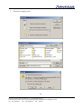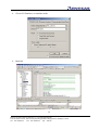
1
致尊敬的顾客 关于产品目录等资料中的旧公司名称 NEC电子公司与株式会社瑞萨科技于2010年4月1日进行业务整合(合并),整合后的 新公司暨“瑞萨电子公司”继承两家公司的所有业务。因此,本资料中虽还保留有旧公司 名称等标识,但是并不妨碍本资料的有效性,敬请谅解。 瑞萨电子公司网址:http://www.renesas.com 2010年4月1日 瑞萨电子公司 【发行】瑞萨电子公司(http://www.renesas.com) 【业务咨询】http://www.renesas.com/inquiry Notice 1. 2. 3. 4. 5. 6. 7. All information included in this document is current as of the date this document is issued. Such information, however, is subject to change without any prior notice. Before purchasing or using any Renesas Electronics products listed herein, please confirm the latest product information with a Renesas Electronics sales office. Also, please pay regular and careful attention to additional and different information to be disclosed by Renesas Electronics such as that disclosed through our website. Renesas Electronics does not assume any liability for infringement of patents, copyrights, or other intellectual property rights of third parties by or arising from the use of Renesas Electronics products or technical information described in this document. No license, express, implied or otherwise, is granted hereby under any patents, copyrights or other intellectual property rights of Renesas Electronics or others. You should not alter, modify, copy, or otherwise misappropriate any Renesas Electronics product, whether in whole or in part. Descriptions of circuits, software and other related information in this document are provided only to illustrate the operation of semiconductor products and application examples. You are fully responsible for the incorporation of these circuits, software, and information in the design of your equipment. Renesas Electronics assumes no responsibility for any losses incurred by you or third parties arising from the use of these circuits, software, or information. When exporting the products or technology described in this document, you should comply with the applicable export control laws and regulations and follow the procedures required by such laws and regulations. You should not use Renesas Electronics products or the technology described in this document for any purpose relating to military applications or use by the military, including but not limited to the development of weapons of mass destruction. Renesas Electronics products and technology may not be used for or incorporated into any products or systems whose manufacture, use, or sale is prohibited under any applicable domestic or foreign laws or regulations. Renesas Electronics has used reasonable care in preparing the information included in this document, but Renesas Electronics does not warrant that such information is error free. Renesas Electronics assumes no liability whatsoever for any damages incurred by you resulting from errors in or omissions from the information included herein. Renesas Electronics products are classified according to the following three quality grades: “Standard”, “High Quality”, and “Specific”. The recommended applications for each Renesas Electronics product depends on the product’s quality grade, as indicated below. You must check the quality grade of each Renesas Electronics product before using it in a particular application. You may not use any Renesas Electronics product for any application categorized as “Specific” without the prior written consent of Renesas Electronics. Further, you may not use any Renesas Electronics product for any application for which it is not intended without the prior written consent of Renesas Electronics. Renesas Electronics shall not be in any way liable for any damages or losses incurred by you or third parties arising from the use of any Renesas Electronics product for an application categorized as “Specific” or for which the product is not intended where you have failed to obtain the prior written consent of Renesas Electronics. The quality grade of each Renesas Electronics product is “Standard” unless otherwise expressly specified in a Renesas Electronics data sheets or data books, etc. “Standard”: 8. 9. 10. 11. 12. Computers; office equipment; communications equipment; test and measurement equipment; audio and visual equipment; home electronic appliances; machine tools; personal electronic equipment; and industrial robots. “High Quality”: Transportation equipment (automobiles, trains, ships, etc.); traffic control systems; anti-disaster systems; anticrime systems; safety equipment; and medical equipment not specifically designed for life support. “Specific”: Aircraft; aerospace equipment; submersible repeaters; nuclear reactor control systems; medical equipment or systems for life support (e.g. artificial life support devices or systems), surgical implantations, or healthcare intervention (e.g. excision, etc.), and any other applications or purposes that pose a direct threat to human life. You should use the Renesas Electronics products described in this document within the range specified by Renesas Electronics, especially with respect to the maximum rating, operating supply voltage range, movement power voltage range, heat radiation characteristics, installation and other product characteristics. Renesas Electronics shall have no liability for malfunctions or damages arising out of the use of Renesas Electronics products beyond such specified ranges. Although Renesas Electronics endeavors to improve the quality and reliability of its products, semiconductor products have specific characteristics such as the occurrence of failure at a certain rate and malfunctions under certain use conditions. Further, Renesas Electronics products are not subject to radiation resistance design. Please be sure to implement safety measures to guard them against the possibility of physical injury, and injury or damage caused by fire in the event of the failure of a Renesas Electronics product, such as safety design for hardware and software including but not limited to redundancy, fire control and malfunction prevention, appropriate treatment for aging degradation or any other appropriate measures. Because the evaluation of microcomputer software alone is very difficult, please evaluate the safety of the final products or system manufactured by you. Please contact a Renesas Electronics sales office for details as to environmental matters such as the environmental compatibility of each Renesas Electronics product. Please use Renesas Electronics products in compliance with all applicable laws and regulations that regulate the inclusion or use of controlled substances, including without limitation, the EU RoHS Directive. Renesas Electronics assumes no liability for damages or losses occurring as a result of your noncompliance with applicable laws and regulations. This document may not be reproduced or duplicated, in any form, in whole or in part, without prior written consent of Renesas Electronics. Please contact a Renesas Electronics sales office if you have any questions regarding the information contained in this document or Renesas Electronics products, or if you have any other inquiries. (Note 1) “Renesas Electronics” as used in this document means Renesas Electronics Corporation and also includes its majorityowned subsidiaries. (Note 2) “Renesas Electronics product(s)” means any product developed or manufactured by or for Renesas Electronics. RSSHEUM0004 - 0200 16 R8C/2G/2H Power Meter Platform R8C Tiny Series – MCU Microcomputer Development Environment System Rev.2.00 Oct. 30, 2007 1 2 - - Renesas System Solutions (Beijing) Co., Ltd. Shanghai Branch Unit 207 AZIA Center, NO 1233 Lujiazui Ring Road, Pudong District, Shanghai, China Tel: 021-68880556 Fax: 021-68880559 Zip: 200120 Power Meter Platform ( R8C/2G/2H) User’s Manual RS-SH 2nd Edition Published by: Renesas System Solutions (Beijing) Co., Ltd., Shanghai Branch Date: November 5, 2007 Version 2.00 © 2007 Renesas System Solutions (Beijing) Co., Ltd., Shanghai Branch, All rights reserved. Trademarks a) General All brand or product names used in this manual are trademarks or registered trademarks of their respective companies or organizations. b) Specific Microsoft Windows is registered trademarks of Microsoft Corporation. Pentium is a registered trademark of Intel. 3 - - Renesas System Solutions (Beijing) Co., Ltd. Shanghai Branch Unit 207 AZIA Center, NO 1233 Lujiazui Ring Road, Pudong District, Shanghai, China Tel: 021-68880556 Fax: 021-68880559 Zip: 200120 IMPORTANT INFORMATION READ this user’s manual before using this dashboard platform. KEEP the user’s manual handy for future reference. Do not attempt to use the dashboard platform until you fully understand its layout concept. MCU: Throughout this document, the term “MCU” shall be defined as the Renesas M16C Tiny series, R8C/2G/2H microcomputers. Improvement Policy: Renesas System Solutions (Beijing) Co., Ltd., Shanghai Branch (hereafter collectively referred to as Renesas) pursues a policy of continuing improvement in design, performance, and safety of this evaluation board. Renesas reserves the right to change, wholly or partially, the specifications, design, user’s manual and other documentation at any time without notice. Target User of the Product: This product should only be used by those who have carefully read and thoroughly understood the information as well as restrictions contained in the user’s manual. Do not attempt to use the product until you fully understand its mechanism. Support: Regarding support for the product, no services are provided at all. 4 - - Renesas System Solutions (Beijing) Co., Ltd. Shanghai Branch Unit 207 AZIA Center, NO 1233 Lujiazui Ring Road, Pudong District, Shanghai, China Tel: 021-68880556 Fax: 021-68880559 Zip: 200120 LIMITED WARRANTY Renesas warrants its products to be manufactured in accordance with published specifications and free from defects in material and/or workmanship. The foregoing warranty does not cover damage caused by fair wear and tear, abnormal store condition, incorrect use, accidental misuse, abuse, neglect, corruption, misapplication, addition or modification or by the use with other hardware or software, as the case may be, with which the product is incompatible. No warranty of fitness for a particular purpose is offered. The user assumes the entire risk of using the product. Any liability of Renesas is limited exclusively to the replacement of defective materials or workmanship. DISCLAIMER RENESAS MAKES NO WARRANTIES, EITHER EXPRESS OR IMPLIED, ORAL OR WRITTEN, EXCEPT AS PROVIDED HEREIN, INCLUDING WITHOUT LIMITATION THEREOF, WARRANTIES AS TO MARKETABILITY, MECRCHANTABILITY, FITNESS FOR ANY PARTICULAR PURPOSE OR USE, OR AGAINST INFRINGEMENT OF ANY PATENT. IN NO EVENT SHALL RENESAS BE LIABLE FOR ANY DIRECT, INCIDENTAL OR CONSEQUENTIAL DAMAGES OF ANY NATURE, OR LOSSES OR EXPENSES RESULTING FROM ANY DEFECTIVE PRODUCT, THE USE OF ANY PRODUCT OR ITS DOCUMENTATION, EVEN IF ADVISED OF THE POSSIBILITY OF SUCH DAMAGES. EXCEPT AS EXPRESSLY STATED OTHERWISE IN THIS WARRANTY, THIS PRODUCT IS SOLD “AS IS”. AND YOU MUST ASSUME ALL RISK FOR THE USE AND RESULTS OBTAINED FROM THE PRODUCT. 5 - - Renesas System Solutions (Beijing) Co., Ltd. Shanghai Branch Unit 207 AZIA Center, NO 1233 Lujiazui Ring Road, Pudong District, Shanghai, China Tel: 021-68880556 Fax: 021-68880559 Zip: 200120 All Right Reserved: This user’s manual and product are copyrighted and all rights are reserved by Renesas. No part of this user’s manual, all or part, any be reproduced or duplicated in any form, in hardcopy or machine-readable form, by any means available without Renesas’ prior written consent. Other Important Things to Keep in Mind: 1. Circuitry and other examples described herein are meant merely to indicate the characteristics and performance of Renesas Technology‘s semiconductor products. Renesas assumes no responsibility for any intellectual property claims or other problems that may result from applications based on the examples described herein. 2. No license is granted by implication or otherwise under any patents or other rights of any third party or Renesas. 3. MEDICAL APPLICATIONS: Renesas Technology’s products are not authorized for use in MEDICAL APPLICATIONS without the written consent of the appropriate officer of Renesas Technology. Such use includes, but is not limited to, use in life support systems. Buyers of Renesas Technology’s products are requested to notify the relevant Renesas Technology when planning to use the products in MEDICAL APPLICATIONS. Limited Anticipation of Danger: Renesas cannot anticipate every possible circumstance that might involve a potential hazard. The warnings in this user’s manual and on the product are therefore not all inclusive. Therefore, you must use the product safely at your own risk. 6 - - Renesas System Solutions (Beijing) Co., Ltd. Shanghai Branch Unit 207 AZIA Center, NO 1233 Lujiazui Ring Road, Pudong District, Shanghai, China Tel: 021-68880556 Fax: 021-68880559 Zip: 200120 PREFACE About this manual This user’s manual is written for Renesas R8C/2G/2H Platform Demonstration Board. It describes the hardware and software specifications of this platform. Please use this user’s manual to understand the hardware and how to design R8C/2G/2H-software for the power meter application. Section 1 Overview and Features Give an introduction to the hardware and software specifications of the platform. Section 2 System Requirements Introduce the requirements of the system. Section 3 Block Diagram Give an overview on the functional modules of the platform. Section 4 Schematic Diagram Give a description of each circuits or modules schematically and functionally. Section 5 Bill of Components Give a detailed list of the components included in the system. Section 6 Software Description Give a function description of each software module and peripherals used by the sample software. Section 7 Sample Software Flowchart Give the detailed Sample Software flowchart description for the power meter application. Section 8 Using E8 Emulator for Debugging Demonstrate how to debug in HEW environment by using E8 emulator. 7 - - Renesas System Solutions (Beijing) Co., Ltd. Shanghai Branch Unit 207 AZIA Center, NO 1233 Lujiazui Ring Road, Pudong District, Shanghai, China Tel: 021-68880556 Fax: 021-68880559 Zip: 200120 Contents 1. Overview & Features ...................................................................................................................2 2. System Requirements...................................................................................................................3 3. Block Diagram .............................................................................................................................4 4. Schematic Diagram......................................................................................................................5 4.1 Sampling and low voltage detecting ..........................................................................5 4.2 ADE7755 circuit ........................................................................................................6 4.3 LCM display module .................................................................................................7 4.4 MCU Part ...................................................................................................................7 4.5 EEPROM Circuit .....................................................................................................10 4.6 Infrared Transceiver Circuit.....................................................................................10 4.7 Power pulse input circuit .........................................................................................11 4.8 Temperature measurement logic circuit...................................................................11 4.9 Circuit Board Layout ...............................................................................................12 5. Bill of Components ....................................................................................................................13 6. Software Description .................................................................................................................15 6.1 I2C............................................................................................................................16 6.2 UART.......................................................................................................................17 6.3 LCD..........................................................................................................................17 6.4 HC164 ......................................................................................................................18 6.5 ADE7755 .................................................................................................................18 6.6 Infrared Send............................................................................................................19 6.7 Infrared Receive.......................................................................................................19 6.8 Real-Time Clock......................................................................................................20 6.9 Frequency Turning...................................................................................................20 6.10 Power Down...........................................................................................................21 6.11 Low Voltage Detection ..........................................................................................22 6.12 Watchdog ...............................................................................................................22 7. Sample Software Flowchart.......................................................................................................23 7.1 Main Function..........................................................................................................23 7.2 I2C............................................................................................................................24 7.3 UART.......................................................................................................................25 7.4 LCD..........................................................................................................................26 7.5 HC164 ......................................................................................................................26 7.6 ADE7755 .................................................................................................................27 7.7 Infrared Send............................................................................................................28 7.8 Infrared Receive.......................................................................................................29 7.9 Real-time Clock .......................................................................................................30 7.10 Oscillator Frequency Turning ................................................................................31 7.11 Power Down...........................................................................................................32 7.12 Low Power Detection ............................................................................................32 8. Using E8 Emulator for Debugging ............................................................................................33 1 1. Overview & Features The R8C/2G/2H power meter platform is used to promote R8C/2G/2H for the single-phase power meter application. Emulator E8 is used for software development. The demonstration package should be given to customers with a demonstration board, a reference manual and a software package. Hardware Specification: - Main clock circuitry, MAX 8MHz (onchip) Reset circuitry DC 6-9V input for DC5V regulation Internal Real-Time Clock (RTC) External 8Kb EEPROM (controlled by IIC) ADE7755 connector circuitry RS485 connector circuitry Infrared circuitry Two LED Dot-matrix LCD (controlled by HC164) Temperature measurement circuit Software Specification: - SCI, LCD drivers Infrared driver EEPROM driver ADE7755 driver Power Meter Emulation RS485 driver Watchdog Oscillator frequency turning Reference Manual Specification: - Demonstration board schematic Description of each hardware functions Material list Description of each software module in the software package 2 - - Renesas System Solutions (Beijing) Co., Ltd. Shanghai Branch Unit 207 AZIA Center, NO 1233 Lujiazui Ring Road, Pudong District, Shanghai, China Tel: 021-68880556 Fax: 021-68880559 Zip: 200120 2. System Requirements - 220VAC power supply Emulator, E8 HEW installed in PC 3 - - Renesas System Solutions (Beijing) Co., Ltd. Shanghai Branch Unit 207 AZIA Center, NO 1233 Lujiazui Ring Road, Pudong District, Shanghai, China Tel: 021-68880556 Fax: 021-68880559 Zip: 200120 3. Block Diagram The following diagram describes the system blocks and the figure shows the system components, they help you have a general concept of this application. 4 - - Renesas System Solutions (Beijing) Co., Ltd. Shanghai Branch Unit 207 AZIA Center, NO 1233 Lujiazui Ring Road, Pudong District, Shanghai, China Tel: 021-68880556 Fax: 021-68880559 Zip: 200120 4. Schematic Diagram 4.1 Sampling and low voltage detecting 3 1 Header 2 R1 10 AC2 T1 AC1 AC220V V1N0 R2 10 N Trans R5 5.1K V2P0R6 220K R3 100 R7 100K R8 100K R9 220K 1 3 SW1 2 SW-SPDT D1 4148 D2 IC2 V+ D3 4148 LM7805 +5 Vin Vout GND 1N4001 D4 4148 V1P0 C2 C4 104 100uF R33 5.1K C3 D5 4148 100uF C5 104 VCC_CPU D6 4148 BT1 J1 VR10 27K Jumper R11 3.3K R12 510 Pdown C6 R13 10M R14 9.1M LVD P XP2 IC4 For safety purpose, we use a transformer on this platform. In actual application, and for cost down, there is such transformer. This part is the sampling and low voltage detecting circuit. The current circuit consists of R2, R3 and R33. It gives sine current signal to ADE7755’s V1P pin and V1N pin. The voltage circuit consists of R5, R6, R7, R8 and R9. It gives sine voltage signal to ADE7755’s V2P pin and V2N pin. Power off circuit consists of R10, R11 and R12. If power off, MCU will not detect plus signal in a short time. 5 - - Renesas System Solutions (Beijing) Co., Ltd. Shanghai Branch Unit 207 AZIA Center, NO 1233 Lujiazui Ring Road, Pudong District, Shanghai, China Tel: 021-68880556 Fax: 021-68880559 Zip: 200120 The low voltage circuit consists of R13 and R14. It sends a voltage signal to MCU’s voltage compare port. If the voltage of batter is below 2.4V, an interrupt will occur. 4.2 ADE7755 circuit IC3 VCC C6 0.033uF Counter1 1 2 3 4 C7 5 V1P 0.033uF V1N 6 V2P 7 V2N 8 485_/RST9 10 11 12 DVDD ACDC AVDD NC V1P V1N V2P V2N RESET Vref AGND SCF F1 F2 CF REVP DGND NV CLKOUT CLKIN G0 G1 S0 S1 24 23 22 21 20 19 18 17 16 15 14 13 F1_out F2_out CF REVP C8 22uF X1 3.58M C11 22uF 1 2 C9 C10 4700pF 4700pF +5 ADE7755 C12 C13 0.033uF 10uF/10V This part is the ADE7755 circuit; it executes current and voltage sampling and output power measurement pluses. This power meter platform has a LCD display module except the mechanical counter. The ADE7755 is an accurate electrical energy measurement IC intended for use in singlephase distribution systems. It provides instantaneous and average real power based on line current and voltage. The part specifications surpass the accuracy requirements as stated in the IEC61036 standard. The only analog circuitry used in the ADE7755 is in the ADCs and reference circuit. All other signal processing (e.g., multiplication and filtering) is carried out in the digital domain. This approach provides superior stability and accuracy over extremes in environmental conditions and over time. 6 - - Renesas System Solutions (Beijing) Co., Ltd. Shanghai Branch Unit 207 AZIA Center, NO 1233 Lujiazui Ring Road, Pudong District, Shanghai, China Tel: 021-68880556 Fax: 021-68880559 Zip: 200120 Pluse sent to counter (F1_out/F2_out) 4.3 LCM display module +5 IC8 S_DAT S_CLK 1 2 8 3 4 5 6 A1 Vcc A2 RESET CLOCK GND Qa Qh Qb Qg Qc Qf Qd Qe 14 9 7 13 12 11 10 C22 104 DB7 DB6 DB5 DB4 74HC164 +5 XP2 GND Vo RW DB0 DB2 DB4 DB6 1 2 3 4 5 6 7 8 9 10 11 12 13 14 +5 RS E DB1 DNB3 DB5 DB7 LCM R32 10K R33 10K MCU drivers HC164, and expands I/O to driver LCD module. LCD module is used to display power counter. 4.4 MCU Part For general purpose, I/Os of R8C/2G is assigned the same as R8C/2H’s. The following figure shows the MCU part, which belong to both of R8C/2G and R8C/2H, and these parts are used in this application. 7 - - Renesas System Solutions (Beijing) Co., Ltd. Shanghai Branch Unit 207 AZIA Center, NO 1233 Lujiazui Ring Road, Pudong District, Shanghai, China Tel: 021-68880556 Fax: 021-68880559 Zip: 200120 MCU (R8C/2G or R8C/2H) detects the signal from ADE7755, counts the electrical energy and displays it on LCD. For total system, MCU detects power off signal, low voltage signal, and according to these 8 - - Renesas System Solutions (Beijing) Co., Ltd. Shanghai Branch Unit 207 AZIA Center, NO 1233 Lujiazui Ring Road, Pudong District, Shanghai, China Tel: 021-68880556 Fax: 021-68880559 Zip: 200120 signals, it will execute the low power consumption function. MCU reads and writes system data to EEPROM (24C0X). MCU communicates with outers through ADE485 and infrared transmitting and receiving circuits. MCU transmits UART signals through P64 and receivers signals from P63, The waveform looks like as below: P37 and P17 are Infrared output and input ports. In order to sending infrared, the timer A and timer B are used. Timer A is use to generate 38KHZ carrier wave. Timer B is used to count widths of the pluses. Transmitting waveform 9 - - Renesas System Solutions (Beijing) Co., Ltd. Shanghai Branch Unit 207 AZIA Center, NO 1233 Lujiazui Ring Road, Pudong District, Shanghai, China Tel: 021-68880556 Fax: 021-68880559 Zip: 200120 Receiving waveform 4.5 EEPROM Circuit Utilize two I/Os to drive 24C0X. 24C0X is used to store system setting data and power measurement data. +5 R21 R22 10K 10K +5 IC5 1 2 3 4 A0 A1 A2 Vss 8 7 6 5 Vcc WP SCL SDA PSCL1 PSDA1 24C01 4.6 Infrared Transceiver Circuit This circuit executes setting and modifying parameters of power meter, and reads data from customer through it. VCC Vdd Vss +5 R34 10 2 1 Ir_R 3 Ouput IC7 HS3800 R30 Ir_T IR LED2 C25 10uF 220 R31 220 TR1 9013 10 - - Renesas System Solutions (Beijing) Co., Ltd. Shanghai Branch Unit 207 AZIA Center, NO 1233 Lujiazui Ring Road, Pudong District, Shanghai, China Tel: 021-68880556 Fax: 021-68880559 Zip: 200120 HS0038 is a receiver; it is a 38 kHz infrared demodulator, it outputs pulse to MCU’s INT1 pin. Timer RA is used as a carry-wave generator, it outputs 38 kHz PWM. MCU sends the data through the infrared diode. 4.7 Power pulse input circuit The power pulse of ADE7755 output is sent to MCU by opt-isolator for calculating. +5 CF R26 820 LED1 R27 10K 1 IC6 4 2 Red CF1 3 PS2501 LED2 REVP Green R29 86K 4.8 Temperature measurement logic circuit Use three pins of MCU, one exact resistance R35, one thermal-sensitive-resistance RT, one normal resistance and one capacitance for temperature measurement. Temperature measurement process: This circuit generally shows the basic logic of temperature measurement. Charge C27 through R34 and let it then discharge through R35 or RT, record the discharging time T1 and 11 - - Renesas System Solutions (Beijing) Co., Ltd. Shanghai Branch Unit 207 AZIA Center, NO 1233 Lujiazui Ring Road, Pudong District, Shanghai, China Tel: 021-68880556 Fax: 021-68880559 Zip: 200120 T2 respectively. R35/T1=RT/T2, get the RT value since R35 is known already (exact resistance, 100k ohm). Look up the R-T table which provided according to the thermalsensitive-resistance characteristic and obtain the current temperature. 4.9 Circuit Board Layout The following figure shows the outline of the board. Top layer and bottom layer 12 - - Renesas System Solutions (Beijing) Co., Ltd. Shanghai Branch Unit 207 AZIA Center, NO 1233 Lujiazui Ring Road, Pudong District, Shanghai, China Tel: 021-68880556 Fax: 021-68880559 Zip: 200120 5. Bill of Components Designator Footprint LibRef Quantity BT1 Battery Battery 1 C1 RC 0805_1/10W CAP [SMT] 1 C2 CAP(5mm_D6.3) ELECTRONIC2 1 C3 CAP(5mm_D6.3) ELECTRONIC2 1 C4 RC 0805_1/10W CAP [SMT] 1 C5 RC 0805_1/10W CAP [SMT] 1 C6 RC 0805_1/10W CAP [SMT] 1 C7 RC 0805_1/10W CAP [SMT] 1 C8 CAP(5mm_D6.3) ELECTRONIC2 1 C9 RC 0805_1/10W CAP [SMT] 1 C10 RC 0805_1/10W CAP [SMT] 1 C11 RC 0805_1/10W CAP [SMT] 1 C12 RC 0805_1/10W CAP [SMT] 1 C13 RC 0805_1/10W CAP [SMT] 1 C14 RC 0805_1/10W CAP [SMT] 1 C15 CAP(5mm_D6.3) ELECTRONIC2 1 C16 RC 0805_1/10W CAP [SMT] 1 C17 CAP(5mm_D6.3) ELECTRONIC2 1 C18 RC 0805_1/10W CAP [SMT] 1 C19 RC 0805_1/10W CAP [SMT] 1 C20 RC 0805_1/10W CAP [SMT] 1 C21 RC 0805_1/10W CAP [SMT] 1 C22 RC 0805_1/10W CAP [SMT] 1 C23 RC 0805_1/10W CAP [SMT] 1 C24 RC 0805_1/10W CAP [SMT] 1 C25 RC 0805_1/10W CAP [SMT] 1 C26 RC 0805_1/10W CAP [SMT] 1 Counter1 Counter Counter 1 D1 Diode 1206 Diode 1 D2 DIODE(10.16) Diode 1 D3 Diode 1206 Diode 1 D4 Diode 1206 Diode 1 D5 Diode 1206 Diode 1 D6 Diode 1206 Diode 1 IC1 SOP8 ADM485 1 IC2 TO263 D-PAK Volt Reg 1 IC3 SOP8 24XX 1 IC4 TSSO8X6-G24 AD7755 1 IC5 Receiver RECEIVER 1 IC6 R8C2G_Aduptor R8C/2G/2H 1 IC7 SOT89 Header 3 1 IC8 SOP14 74HC164 1 IC9 DIP4 Optoisolator1 1 IR1 LED .3 LED2 1 13 - - Renesas System Solutions (Beijing) Co., Ltd. Shanghai Branch Unit 207 AZIA Center, NO 1233 Lujiazui Ring Road, Pudong District, Shanghai, China Tel: 021-68880556 Fax: 021-68880559 Zip: 200120 J1 HDR1X2 Jumper 1 LED1 Diode 0805 LED2 1 LED2 Diode 0805 LED2 1 P1 HDR1X3 Header 3 1 R1 RC 0805_1/10W RES2 [SMT] 1 R2 RC 0805_1/10W RES2 [SMT] 1 R3 RC 0805_1/10W RES2 [SMT] 1 R5 RC 0805_1/10W RES2 [SMT] 1 R6 RC 0805_1/10W RES2 [SMT] 1 R7 RC 0805_1/10W RES2 [SMT] 1 R8 RC 0805_1/10W RES2 [SMT] 1 R9 RC 0805_1/10W RES2 [SMT] 1 R10 RC 0805_1/10W RES2 [SMT] 1 R11 RC 0805_1/10W RES2 [SMT] 1 R12 RC 0805_1/10W RES2 [SMT] 1 R13 RC 0805_1/10W RES2 [SMT] 1 R14 RC 0805_1/10W RES2 [SMT] 1 R15 RC 0805_1/10W RES2 [SMT] 1 R16 RC 0805_1/10W RES2 [SMT] 1 R17 RC 0805_1/10W RES2 [SMT] 1 R18 RC 0805_1/10W RES2 [SMT] 1 R19 RC 0805_1/10W RES2 [SMT] 1 R20 RC 0805_1/10W RES2 [SMT] 1 R21 RC 0805_1/10W RES2 [SMT] 1 R22 RC 0805_1/10W RES2 [SMT] 1 R23 RC 0805_1/10W RES2 [SMT] 1 R24 RC 0805_1/10W RES2 [SMT] 1 R25 RC 0805_1/10W RES2 [SMT] 1 R26 RC 0805_1/10W RES2 [SMT] 1 R27 RC 0805_1/10W RES2 [SMT] 1 R28 RC 0805_1/10W RES2 [SMT] 1 R29 RC 0805_1/10W RES2 [SMT] 1 R30 RC 0805_1/10W RES2 [SMT] 1 R31 RC 0805_1/10W RES2 [SMT] 1 R32 RC 0805_1/10W RES2 [SMT] 1 R33 RC 0805_1/10W RES2 [SMT] 1 SW1 SW [MTS-102] SW-SPDT 1 T1 Transformer TDA-8-103 Trans 1 TR1 SOT23-G3 NPN 1 X1 Crystal_1 XTAL 1 X2 HDR1X2 XTAL 1 XP1 XH4(2) Header 4 1 XP2 Power connectorLN Header 2 1 XP3 HDR2X7 Header 7X2 1 XP4 E8 CONNECTOR Header 7X2 1 14 - - Renesas System Solutions (Beijing) Co., Ltd. Shanghai Branch Unit 207 AZIA Center, NO 1233 Lujiazui Ring Road, Pudong District, Shanghai, China Tel: 021-68880556 Fax: 021-68880559 Zip: 200120 6. Software Description The R8C/2G/2H Demonstration Set accompanies with a software package, which contains 20 software modules. Designers may use these modules as a reference to start their design. The following figure illustrates the software structure. Some of the modules utilize the MCU peripherals and I/O. The following table describes the function of each software module. Table– The Function of Software Module 1 File name Software Modules Function hwsetup.c Oscillator selection LVD Provide main clock, substance clock and on-chip oscillator clocks, three modes for choices Provide a low voltage detection interface timerA_init Initialize timer RA, timer RA is used to output 38 kHz PWM. timerB_init Int1_init Initialize timer RB, timer RB is used as a timer to count widthes of infrared plus. Initialize timer RE, timer RE is used as a RTC; it will be interrupted every second. Initialize TXD and RXD ports; both of the two ports are used as UART ports. Set p10 as a voltage compare port, the detection voltage is set to1.24V Set timer RF as a timer, the timer of interrupt exacting is 0.1ms, it is used to count the width of infrared pulses. Int1 is used as infrared input port. It is used to detect infrared plus. WDT_init Set WDT interval time. timerE_init UART485_init Comparator_init timerF_init 2 I2C.c I2C Provide a standard I2C protocol interface to the upper module 3 interrupt_2G.c Infrared send Provide a infrared data sending interface Infrared receive Provide a infrared data receiving interface 4 lcd.c UART Provide an interface to transmit/receive data to/from the UART2 ADE7755 Provide an interface to count the pulses from the ADE7755 LCD Provide a Man to Machine Interface (MMI) for displaying message HC164 Provide an interface to drive LCD using a serial-in parallel-out shift register Provide a real-time clock to the system 5 Rtimer.c Real-Time Clock 15 - - Renesas System Solutions (Beijing) Co., Ltd. Shanghai Branch Unit 207 AZIA Center, NO 1233 Lujiazui Ring Road, Pudong District, Shanghai, China Tel: 021-68880556 Fax: 021-68880559 Zip: 200120 6 Turn_f.c 7 RDB_28_2G.c Frequency Turning Power Down Provide an interface to adjust the oscillator frequency error. Provide wait and stop-mode to lower power consumption Main Uart2 Watch Dog Power Down ADE 7755 RealTime Clock I2C LCD LVD Oscillator Selection Infrared Send Infrared Receive Timer RA&RB TXD2 RXD2 Frequency Turning HC164 Timer RA P14 P15 P05 P06 P07 INT4 INT1&Timer RF KI1 P12 P13 Timer RE VCMP1 Software Module MCU Peripherals / IO A depends on B B A Figure- Software Structure 6.1 I2C Software Module: Included in: Dependencies: Functions: I2C I2C.c global.h Provide an interface for the upper module to control/access the external module through the I2C. Procedure call Procedure Name: Function: Parameter return: Parameter Input: i2cread Read data from the external device through the I2C None Parameter Type Function Raddress Rrampoint Rbytelength char char* char The device address of external device The start location where the data start The length of data to read 16 - - Renesas System Solutions (Beijing) Co., Ltd. Shanghai Branch Unit 207 AZIA Center, NO 1233 Lujiazui Ring Road, Pudong District, Shanghai, China Tel: 021-68880556 Fax: 021-68880559 Zip: 200120 Procedure Name: Function: Parameter return: Parameter Input: i2cwrite Write data to the external device through the I2C None Parameter Type Function Waddress Wrampoint Wbytelength char char* char The device address of external device The start location where the data start The length of data to write 6.2 UART Software Module: Included in: Dependencies: Functions: UART Interrrupt_2G.c & hwsetup.c global.h Provide an interface for the upper module to access the MCU peripheral UART. Procedure call Procedure Name: Function: Parameter return: Parameter Input: UART485_init It is the initialization process, which should be run before using any UART2 None None Procedure Name: Function: Parameter return: Parameter Input: uart2T_int Send the data from the UART2 port to the external device None None Procedure Name: Function: Parameter return: Parameter Input: uart2R_int The data receive of UART2 port from the external device None None 6.3 LCD Software Module: LCD Include in: lcd.c Dependencies: global.h Functions: Provide an interface for the user to display the message on the LCD Procedure call 17 - - Renesas System Solutions (Beijing) Co., Ltd. Shanghai Branch Unit 207 AZIA Center, NO 1233 Lujiazui Ring Road, Pudong District, Shanghai, China Tel: 021-68880556 Fax: 021-68880559 Zip: 200120 Procedure Name: Function: Parameter return: Parameter Input: InitialiseDisplay It is the initialization process, which should be run before using any LCD procedures None None Procedure Name: Function: Parameter return: Parameter Input: DisplayString Display the data on the LCD None Parameter Type position string Function unsigned char _far char* The device address of external device The start position of the LCD to display 6.4 HC164 Software Module: HC164 Included in: lcd.c Dependencies: global.h Functions: Provide an interface to drive LCD using a serial-in parallel-out shift register Procedure call Procedure Name: Function: Parameter return: Parameter Input: HC164 Provide an interface to drive LCD using a serial-in parallel-out shift register None None 6.5 ADE7755 Software Module: Included in: Dependencies: Functions: ADE7755 Driver Interrrupt_2G.c global.h Provide a function to count the pulses from the ADE7755, after calculation they would be displayed on LCD. Procedure call Procedure Name: Function: Parameter return: Parameter Input: Key_int Provide a function to count the pulses from the ADE7755, after calculation they would be displayed on LCD None None 18 - - Renesas System Solutions (Beijing) Co., Ltd. Shanghai Branch Unit 207 AZIA Center, NO 1233 Lujiazui Ring Road, Pudong District, Shanghai, China Tel: 021-68880556 Fax: 021-68880559 Zip: 200120 6.6 Infrared Send Software Module: Included in: Dependencies: Functions: Infrared Send Interrrupt_2G.c & hwsetup.c global.h Provide an interface for the upper module to transmit data through the infrared. The Infrared Waveform is transmitted through the TRAO port and generated by timer RA, RB. Timer RA is used to generate the carrier frequency, Timer RB is used to control the sending data. Procedure call Procedure Name: Function: Parameter return: Parameter Input: timerA_init It is the initialization process, which should be run before using any infrared send procedures None None Procedure Name: Function: Parameter return: Parameter Input: timerB_int It controls the carrier frequency to generate data code for transmission None None Procedure Name: Function: Parameter return: Parameter Input: code_trans It is a subroutine called in timerB_int, for code transmission None None 6.7 Infrared Receive Software Module: Included in: Dependencies: Functions: Infrared Receive Interrrupt_2G.c & hwsetup.c global.h Provide an interface for the upper module to receive data through the infrared. Timer RF is used to generate 0.1ms timer, INT1 receive the infrared data. Procedure call Procedure Name: Function: Parameter return: Parameter Input: timerF_init It is the initialization process, which should be run before using any infrared receive procedures None None 19 - - Renesas System Solutions (Beijing) Co., Ltd. Shanghai Branch Unit 207 AZIA Center, NO 1233 Lujiazui Ring Road, Pudong District, Shanghai, China Tel: 021-68880556 Fax: 021-68880559 Zip: 200120 Procedure Name: Function: Parameter return: Parameter Input: int1 The data receive of the infrared circuitry from the external device None None Procedure Name: Function: Parameter return: Parameter Input: S_code It is a subroutine called in int1, for code receiving None None 6.8 Real-Time Clock Software Module: Included in: Dependencies: Functions: Real-Time Clock Rtimer.c global.h Provide an interface for the upper module to obtain a real-time clock. User is able to select the procedure to get the current time or date. It is generated by Timer RE. Procedure call Procedure Name: Function: Parameter return: Parameter Input: Procedure Name: Function: Parameter return: Parameter Input: timerE_init It is the initialization process, which should be run before using any real-time clock procedures, user could set the current time and data here. None None Rtimer_E Read the updated time value, data value (including second, minute, hour, day, month, year and also week), they could be displayed onto LCD. None None 6.9 Frequency Turning Software Module: Included in: Dependencies: Functions: frequency turning Turn_f.c global.h Provide an interface for the upper module to correct the oscillator frequency cause by temperature variate. User is able to select the procedure to adjust the frequency. 20 - - Renesas System Solutions (Beijing) Co., Ltd. Shanghai Branch Unit 207 AZIA Center, NO 1233 Lujiazui Ring Road, Pudong District, Shanghai, China Tel: 021-68880556 Fax: 021-68880559 Zip: 200120 Procedure call Procedure Name: Function: Parameter return: Parameter Input: get_error According to the current temperature calculate out the error of the oscillator frequency. None None Procedure Name: Function: Parameter return: Parameter Input: get_T Through temperature measurement logic circuit get the current temperature. None None Procedure Name: Function: Abs_Error According to the difference of each oscillator itself, calculate out the error of its frequency. None None Parameter return: Parameter Input: Procedure Name: Function: Adjust_RTC Adjust RTC clock per hour according to the sum of absolute error of oscillator itself and error cause by temperature variate. None None Parameter return: Parameter Input: 6.10 Power Down Software Module: Included in: Dependencies: Functions: Power Down RDB_28_2G.c global.h Control the power down mode of the MCU Procedure call Procedure Name: Function: Parameter return: Parameter Input: wait_mode_set Enter wait mode. None None 21 - - Renesas System Solutions (Beijing) Co., Ltd. Shanghai Branch Unit 207 AZIA Center, NO 1233 Lujiazui Ring Road, Pudong District, Shanghai, China Tel: 021-68880556 Fax: 021-68880559 Zip: 200120 Procedure Name: Function: Parameter return: Parameter Input: stop_mode_set Enter stop mode. None None 6.11 Low Voltage Detection Software Module: Included in: Dependencies: Functions: LVD hwsetup.c global.h Monitor the VCC input voltage. Procedure call Procedure Name: Function: Parameter return: Parameter Input: Comparator_init When VCMP1 reaches reference voltage or below, VCMP1 interrupt happened. None None 6.12 Watchdog Software Module: Included in: Dependencies: Functions: Watchdog hwsetup.c & RDB_28_2G.c global.h Control the watchdog timer. 22 - - Renesas System Solutions (Beijing) Co., Ltd. Shanghai Branch Unit 207 AZIA Center, NO 1233 Lujiazui Ring Road, Pudong District, Shanghai, China Tel: 021-68880556 Fax: 021-68880559 Zip: 200120 7. Sample Software Flowchart 7.1 Main Function 23 - - Renesas System Solutions (Beijing) Co., Ltd. Shanghai Branch Unit 207 AZIA Center, NO 1233 Lujiazui Ring Road, Pudong District, Shanghai, China Tel: 021-68880556 Fax: 021-68880559 Zip: 200120 7.2 I2C 24 - - Renesas System Solutions (Beijing) Co., Ltd. Shanghai Branch Unit 207 AZIA Center, NO 1233 Lujiazui Ring Road, Pudong District, Shanghai, China Tel: 021-68880556 Fax: 021-68880559 Zip: 200120 7.3 UART 25 - - Renesas System Solutions (Beijing) Co., Ltd. Shanghai Branch Unit 207 AZIA Center, NO 1233 Lujiazui Ring Road, Pudong District, Shanghai, China Tel: 021-68880556 Fax: 021-68880559 Zip: 200120 7.4 LCD 7.5 HC164 26 - - Renesas System Solutions (Beijing) Co., Ltd. Shanghai Branch Unit 207 AZIA Center, NO 1233 Lujiazui Ring Road, Pudong District, Shanghai, China Tel: 021-68880556 Fax: 021-68880559 Zip: 200120 7.6 ADE7755 27 - - Renesas System Solutions (Beijing) Co., Ltd. Shanghai Branch Unit 207 AZIA Center, NO 1233 Lujiazui Ring Road, Pudong District, Shanghai, China Tel: 021-68880556 Fax: 021-68880559 Zip: 200120 7.7 Infrared Send 28 - - Renesas System Solutions (Beijing) Co., Ltd. Shanghai Branch Unit 207 AZIA Center, NO 1233 Lujiazui Ring Road, Pudong District, Shanghai, China Tel: 021-68880556 Fax: 021-68880559 Zip: 200120 7.8 Infrared Receive 29 - - Renesas System Solutions (Beijing) Co., Ltd. Shanghai Branch Unit 207 AZIA Center, NO 1233 Lujiazui Ring Road, Pudong District, Shanghai, China Tel: 021-68880556 Fax: 021-68880559 Zip: 200120 7.9 Real-time Clock 30 - - Renesas System Solutions (Beijing) Co., Ltd. Shanghai Branch Unit 207 AZIA Center, NO 1233 Lujiazui Ring Road, Pudong District, Shanghai, China Tel: 021-68880556 Fax: 021-68880559 Zip: 200120 7.10 Oscillator Frequency Turning 31 - - Renesas System Solutions (Beijing) Co., Ltd. Shanghai Branch Unit 207 AZIA Center, NO 1233 Lujiazui Ring Road, Pudong District, Shanghai, China Tel: 021-68880556 Fax: 021-68880559 Zip: 200120 7.11 Power Down 7.12 Low Power Detection 32 - - Renesas System Solutions (Beijing) Co., Ltd. Shanghai Branch Unit 207 AZIA Center, NO 1233 Lujiazui Ring Road, Pudong District, Shanghai, China Tel: 021-68880556 Fax: 021-68880559 Zip: 200120 8. Using E8 Emulator for Debugging In this section it demonstrates how to use the power meter platform, and how to use the E8 Emulator for debugging. Please follow these steps: 1. Bring out R8C/2G/2H power meter platform. 2. Connect E8 to the platform. Insert the E8 plug into XP4 connector on the platform. 3. Provide power supply to the platform. 4. Insert the power plug into XP2 connector on the platform. 5. Copy the sample software from the CD-ROM to your PC. Note: Do not include blank or Chinese font in the folder name. 6. Open HEW, the following picture appears. 33 - - Renesas System Solutions (Beijing) Co., Ltd. Shanghai Branch Unit 207 AZIA Center, NO 1233 Lujiazui Ring Road, Pudong District, Shanghai, China Tel: 021-68880556 Fax: 021-68880559 Zip: 200120 7. Choose the sample project. 34 - - Renesas System Solutions (Beijing) Co., Ltd. Shanghai Branch Unit 207 AZIA Center, NO 1233 Lujiazui Ring Road, Pudong District, Shanghai, China Tel: 021-68880556 Fax: 021-68880559 Zip: 200120 8. Choose E8 Emulator, set emulator mode. 9. Build all. 35 - - Renesas System Solutions (Beijing) Co., Ltd. Shanghai Branch Unit 207 AZIA Center, NO 1233 Lujiazui Ring Road, Pudong District, Shanghai, China Tel: 021-68880556 Fax: 021-68880559 Zip: 200120 10. Reset. 11. Run. 36 - - Renesas System Solutions (Beijing) Co., Ltd. Shanghai Branch Unit 207 AZIA Center, NO 1233 Lujiazui Ring Road, Pudong District, Shanghai, China Tel: 021-68880556 Fax: 021-68880559 Zip: 200120 Now you can debug and evaluate the platform. Note: About how to use HEW, please refer to the user manual of HEW. . 37 - - Renesas System Solutions (Beijing) Co., Ltd. Shanghai Branch Unit 207 AZIA Center, NO 1233 Lujiazui Ring Road, Pudong District, Shanghai, China Tel: 021-68880556 Fax: 021-68880559 Zip: 200120 Renesas 16-Bit RISC Microcomputer R8C/2G/2H Power Meter Platform User’s manual Publication Date: Rev.2.00, Oct. 30, 2007 Published by: RS-SH Renesas Technology Corp. Renesas System Solution Edited by: RS-SH Renesas System Solution (Beijing) Co., Ltd Shanghai Branch ©2007. Renesas Technology Corp., All rights reserved. Renesas Technology Corp. Sales Strategic Planning Div. Nippon Bldg., 2-6-2, Ohte-machi, Chiyoda-ku, Tokyo 100-0004, Japan RENESAS SALES OFFICES http://www.renesas.com Refer to "http://www.renesas.com/en/network" for the latest and detailed information. Renesas Technology America, Inc. 450 Holger Way, San Jose, CA 95134-1368, U.S.A T el: <1> (408) 382-7500, Fax: <1> (408) 382-7501 Renesas Technology Europe Limited Dukes Meadow, Millboard Road, Bourne End, Buckinghamshire, SL8 5FH, U.K. Tel: <44> (1628) 585-100, Fax: <44> (1628) 585-900 Renesas Technology (Shanghai) Co., Ltd. Unit 204, 205, AZIA Center, No.1233 Lujiazui Ring Rd, Pudong District, Shanghai, China 200120 T el: <86> (21) 5877-1818, Fax: <86> (21) 6887-7898 Renesas Technology Hong Kong Ltd. 7th Floor, North Tower, World Finance Centre, Harbour City, 1 Canton Road, Tsimshatsui, Kowloon, Hong Kong Tel: <852> 2265-6688, Fax: <852> 2730-6071 Renesas Technology Taiwan Co., Ltd. 10th Floor, No.99, Fushing North Road, Taipei, Taiwan T el: <886> (2) 2715-2888, Fax: <886> (2) 2713-2999 Renesas Technology Singapore Pte. Ltd. 1 Harbour Front Avenue, #06-10, Keppel Bay Tower, Singapore 098632 Tel: <65> 6213-0200, Fax: <65> 6278-8001 Renesas Technology Korea Co., Ltd. Kukje Center Bldg. 18th Fl., 191, 2-ka, Hangang-ro, Yongsan-ku, Seoul 140-702, Korea T el: <82> (2) 796-3115, Fax: <82> (2) 796-2145 Renesas Technology Malaysia Sdn. Bhd Unit 906, Block B, Menara Amcorp, Amcorp Trade Centre, No.18, Jalan Persiaran Barat, 46050 Petaling Jaya, Selangor Darul Ehsan, Malaysia Tel: <603> 7955-9390, Fax: <603> 7955-9510 Colophon 6.0 R8C/2G/2H Power Meter Platform User’s manual Microcomputer Development Environment System R8C Tiny Series MCU Notes regarding these materials 1. 2. 3. 4. 5. 6. 7. 8. 9. 10. 11. 12. 13. This document is provided for reference purposes only so that Renesas customers may select the appropriate Renesas products for their use. Renesas neither makes warranties or representations with respect to the accuracy or completeness of the information contained in this document nor grants any license to any intellectual property rights or any other rights of Renesas or any third party with respect to the information in this document. Renesas shall have no liability for damages or infringement of any intellectual property or other rights arising out of the use of any information in this document, including, but not limited to, product data, diagrams, charts, programs, algorithms, and application circuit examples. You should not use the products or the technology described in this document for the purpose of military applications such as the development of weapons of mass destruction or for the purpose of any other military use. When exporting the products or technology described herein, you should follow the applicable export control laws and regulations, and procedures required by such laws and regulations. All information included in this document such as product data, diagrams, charts, programs, algorithms, and application circuit examples, is current as of the date this document is issued. Such information, however, is subject to change without any prior notice. Before purchasing or using any Renesas products listed in this document, please confirm the latest product information with a Renesas sales office. Also, please pay regular and careful attention to additional and different information to be disclosed by Renesas such as that disclosed through our website. (http://www.renesas.com) Renesas has used reasonable care in compiling the information included in this document, but Renesas assumes no liability whatsoever for any damages incurred as a result of errors or omissions in the information included in this document. When using or otherwise relying on the information in this document, you should evaluate the information in light of the total system before deciding about the applicability of such information to the intended application. Renesas makes no representations, warranties or guaranties regarding the suitability of its products for any particular application and specifically disclaims any liability arising out of the application and use of the information in this document or Renesas products. With the exception of products specified by Renesas as suitable for automobile applications, Renesas products are not designed, manufactured or tested for applications or otherwise in systems the failure or malfunction of which may cause a direct threat to human life or create a risk of human injury or which require especially high quality and reliability such as safety systems, or equipment or systems for transportation and traffic, healthcare, combustion control, aerospace and aeronautics, nuclear power, or undersea communication transmission. If you are considering the use of our products for such purposes, please contact a Renesas sales office beforehand. Renesas shall have no liability for damages arising out of the uses set forth above. Notwithstanding the preceding paragraph, you should not use Renesas products for the purposes listed below: (1) artificial life support devices or systems (2) surgical implantations (3) healthcare intervention (e.g., excision, administration of medication, etc.) (4) any other purposes that pose a direct threat to human life Renesas shall have no liability for damages arising out of the uses set forth in the above and purchasers who elect to use Renesas products in any of the foregoing applications shall indemnify and hold harmless Renesas Technology Corp., its affiliated companies and their officers, directors, and employees against any and all damages arising out of such applications. You should use the products described herein within the range specified by Renesas, especially with respect to the maximum rating, operating supply voltage range, movement power voltage range, heat radiation characteristics, installation and other product characteristics. Renesas shall have no liability for malfunctions or damages arising out of the use of Renesas products beyond such specified ranges. Although Renesas endeavors to improve the quality and reliability of its products, IC products have specific characteristics such as the occurrence of failure at a certain rate and malfunctions under certain use conditions. Please be sure to implement safety measures to guard against the possibility of physical injury, and injury or damage caused by fire in the event of the failure of a Renesas product, such as safety design for hardware and software including but not limited to redundancy, fire control and malfunction prevention, appropriate treatment for aging degradation or any other applicable measures. Among others, since the evaluation of microcomputer software alone is very difficult, please evaluate the safety of the final products or system manufactured by you. In case Renesas products listed in this document are detached from the products to which the Renesas products are attached or affixed, the risk of accident such as swallowing by infants and small children is very high. You should implement safety measures so that Renesas products may not be easily detached from your products. Renesas shall have no liability for damages arising out of such detachment. This document may not be reproduced or duplicated, in any form, in whole or in part, without prior written approval from Renesas. Please contact a Renesas sales office if you have any questions regarding the information contained in this document, Renesas semiconductor products, or if you have any other inquiries. © 2008. Renesas Technology Corp., All rights reserved.