1
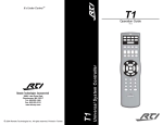
Installation and Operation Guide
®
It’s
Under Control®
It’s Under Control
XP-3
Remote Control Processor
70-210093-22 V1.0
1
XP-3
Remote Control Processor
Copyright © 2011
Remote Technologies Incorporated
All rights reserved.
2
It’s Under Control®
FEDERAL COMMUNICATIONS COMMISSION NOTICE
This equipment has been tested and found to comply with the limits for a
Class B digital device, pursuant to Part 15 of the FCC Rules. These limits
are designed to provide reasonable protection against harmful interference
in a residential installation. Any changes or modifications not expressly
approved by the party responsible for compliance could void the user’s
authority to operate the device.
This equipment generates, uses, and can radiate radio frequency energy
and, if not installed and used in accordance with the instructions, may
cause harmful interference to radio communications. However, there is no
guarantee that interference will not occur in a particular installation.
If this equipment does cause harmful interference to radio or television
reception, which can be determined by turning the equipment off and on,
the user is encouraged to try to correct the interference by one or more of
the following measures:
Reorient or relocate the receiving antenna.
Increase the separation between the equipment and the receiver.
Connect the equipment into an outlet on a circuit different from that to which the receiver is connected.
Consult the dealer or an experienced radio/TV technician for help.
This device complies with Part 15 of the FCC Rules. Operation is subject to
the following two conditions:
1.
This device may not cause harmful interference.
2.
This device must accept any interference received including
interference that may cause undesired operation.
FCC ID: MMURTI1900
IC (Canada): 3166A-RTI1900
N27917
DECLARATION OF CONFORMITY (DOC)
The Declaration of Conformity for this product can be found on the RTI
website at: www.rticorp.com/declaration
3
XP-3
Remote Control Processor
SAFETY SUGGESTIONS
Read Instructions. Read all safety and operating instructions before
operating the unit.
Retain Instructions. Keep the safety and operating instructions for
future reference.
Heed Warnings. Adhere to all warnings on the unit and in the
operating instructions.
Follow Instructions. Follow operating instructions and instructions
for use.
Heat. Keep the unit away from heat sources such as radiators, heat
registers, stoves, etc., including amplifiers that produce heat.
Power Sources. Connect only to the power supply that was included
with the unit.
Power Cord Protection. Route power supply cords so that they are
not likely to be walked on or pinched by items placed on or against
them, paying particular attention to the cords at plugs, at convenient
receptacles, and at the point at which they exit from the unit.
Water and Moisture. Do not use the unit near water—for example,
near a sink, in a wet basement, near a swimming pool, near an open
window, etc.
Object and Liquid Entry. Do not allow objects to fall or liquids to be
spilled into the enclosure through openings.
Cleaning. The unit should be cleaned only as recommended in this
installation and operation guide.
Servicing. Do not attempt any service beyond that described in
the operating instructions. Refer all other service needs to qualified
service personnel.
Damage Requiring Service. The unit should be serviced by qualified
service personnel when:
Objects have fallen or liquid has been spilled into the unit.
The power supply cord or the plug has been damaged.
The unit does not appear to operate normally or exhibits a
marked change in performance.
The unit has been dropped or the enclosure has been damaged.
WARNING!
TO REDUCE THE RISK OF FIRE OR ELECTRIC SHOCK,
DO NOT EXPOSE THE UNIT TO RAIN OR MOISTURE.
4
It’s Under Control®
LIMITED WARRANTY
Remote Technologies Incorporated warrants its products for a period of one
(1) year from the date of purchase from Remote Technologies Incorporated
or an authorized Remote Technologies Incorporated distributor.
This warranty may be enforced by the original purchaser and subsequent
owners during the warranty period, so long as the original dated sales
receipt or other proof of warranty coverage is presented when warranty
service is required. Except as specified below, this warranty covers all
defects in material and workmanship in this product. The following are not
covered by the warranty:
Damage resulting from:
1. Accident, misuse, abuse, or neglect.
2. Failure to follow instructions contained in this Guide.
3. Repair or attempted repair by anyone other than Remote Technologies
Incorporated.
4. Failure to perform recommended periodic maintenance.
5. Causes other than product defects, including lack of skill, competence
or experience of user.
6. Shipment of this product (claims must be made to the carrier).
7. Being altered or which the serial number has been defaced, modified
or removed.
Remote Technologies Incorporated is not liable for any damages caused by
its products or for its failure of its products to perform, including any lost
profits, lost savings, incidental damages, or consequential damages.
Remote Technologies Incorporated is not liable for damages based upon
inconvenience, loss of use of the product, loss of time, interrupted
operation, commercial loss, any claim made by a third party or made by
you for a third party.
Remote Technologies Incorporated’s liability for any defective product is
limited to repair or replacement of the product, at our option.
If your XP-3 Remote Control Processor needs service, please contact
Remote Technologies Incorporated by telephone, fax or E-mail for return
information. Please do not return products to Remote Technologies
Incorporated without return authorization.
5
XP-3
Remote Control Processor
DISCLAIMER
All rights are reserved. No part of this document may be photocopied,
reproduced, or translated without the prior written notice of Remote
Technologies Incorporated.
The information contained in this document is subject to change without
notice. Remote Technologies Incorporated shall not be liable for errors or
omissions contained herein or for consequential damages in connection
with the furnishing, performance, or use of this guide.
Microsoft, Windows, Windows XP, Windows Vista and Windows 7 are
registered trademarks of Microsoft Corporation in the United States and
other countries. ZigBee is a registered trademark of the ZigBee Alliance.
XP-3, Integration Designer, and the RTI logo are registered trademarks of
Remote Technologies Incorporated.
Other brands and their products are trademarks or registered trademarks
of their respective holders.
6
It’s Under Control®
TABLE OF CONTENTS
Federal Communications Commission Notice................3
Safety Suggestions....................................................... 4
Limited Warranty......................................................... 5
Disclaimer.................................................................... 6
Table of Contents......................................................... 7
Chapter 1 - Welcome.................................................... 9
Important Notes, Compatibility, Software Req’s............. 9
Product Contents, Unpacking..................................... 10
Chapter 2 - Features.................................................... 11
XP-3 Diagram.......................................................... 12
Chapter 3 - Installation and Operation........................ 13
Mounting................................................................ 13
Power.................................................................... 14
Connections (Antennas, IR, Modules, etc.).................. 14
RS-232 Cabling/Pinouts............................................ 16
Programming the XP-3............................................. 17
Status LED reference................................................ 17
Setting the Zone Code.............................................. 17
Connection Diagrams............................................... 18
Chapter 4 - Specifications............................................ 21
Chapter 5 - Troubleshooting........................................ 23
Chapter 6 - Service and Support.................................. 25
Index.......................................................................... 27
7
XP-3
8
Remote Control Processor
It’s Under Control®
CHAPTER 1 | WELCOME
Thank you for using the XP-3 Remote Control Processor.
The XP-3 is designed to automate and enhance the operation of A/V,
security, lighting, HVAC, and countless other devices in a commercial
or residential environment. The XP-3 is packed with features including
a variety of control options, such as two-way RS-232, relays, Ethernet,
and routable IR. The processor also has a built-in 2.4 GHz ZigBee® RF
transceiver for sophisticated bidirectional communication with compatible
RTI remote controls. The XP-3 can also be configured to support 433MHz
RF communication using additional RTI accessories and wireless remotes.
For complete control in any room, the XP-3 even allows powerful two-way
control with Ethernet enabled RTI in-wall controllers, and reliable one-way
control with compatible RTI in-wall products.
IMPORTANT NOTES
Please read these important notes about the XP-3:
The XP-3 should be placed in an area where it is around normal room
temperature (between 60°F to 90°F).
Avoid installing the XP-3 in a location where it can come in contact
with direct sunlight.
Do not let the XP-3 get wet. It should not be handled with wet hands
or placed in an area where it could get wet.
Do not subject the XP-3 to smoke, dust, or vibrations.
Only use the power supply that is specified for the XP-3. Using the
wrong type of power supply may result in damage.
Do not disassemble the unit. Service of the XP-3 should be performed
by authorized personnel only. Service of the XP-3 performed by
unauthorized personnel will invalidate its warranty.
SOFTWARE REQUIREMENTS
The recommended minimum system requirements needed to run the
Integration Designer® software are as follows:
Windows XP®, Windows Vista®, Windows 7®or later version of Microsoft
operating system.
9
XP-3
Remote Control Processor
CHAPTER 1 | PRODUCT CONTENTS
Contents within the box include the following items:
• One (1) XP-3 Remote Control Processor
• One (1) Installation Guide
• One (1) Universal Power Supply
• One (1) Power Cord
• One (1) RS-232 Adapter
• Two (2) Phoenix Connectors
• One (1) XP-3 Removable Antenna
• One (1) XP-3 Mounting Plate with screws
UNPACKING AND INSPECTION
After unpacking your new XP-3 Remote Control Processor, save all of the
packing materials in case you ever have to ship the unit.
Thoroughly inspect the XP-3 and packing materials for signs of damage.
Report any damage to the carrier immediately. Report any equipment
malfunctions to RTI or an authorized RTI distributor.
10
It’s Under Control®
CHAPTER 2 | FEATURES
The XP-3 provides superior quality and reliability as well as these specific
features:
Powerful 32bit, 533MHz CPU.
128Mb of non-volatile Flash memory stores your system configuration
even when power is not present.
One multi-purpose I/O port supports optional RTI power sensing and
communications modules.
Two IR output ports.
Two assignable voltage sense inputs.
Two programmable relay outputs.
One two-way RS-232 port for bi-directional communication with
supported devices.
Integrated 10/100Base-T Ethernet port for programming, control and
two-way communication with compatible devices.
Integrated 10/100Base-T Ethernet port supports Power-over-Ethernet
(POE) Class 3.
Built-in astronomical clock for time-based events and sleep timers.
Built-in 2.4GHz ZigBee® RF transceiver module and removable
antenna.
Compatible with industry standard IR emitters and blasters.
Configurable for communication with RTI 433MHz RF remote controls
using an RTI RM-433 antenna, and support for RTI in-wall products.
All output ports incorporate both short-circuit and overload protection.
Variable IR output on all ports.
Programmed using the RTI Integration Designer Software.
USB 2.0 and Ethernet programming.
Field upgradable firmware.
11
XP-3
Remote Control Processor
CHAPTER 2 | FEATURES
IR Output Adjustment Controls
Status Lights
Antenna
Reset Button
RS-232
Ethernet
USB
Power
Supply
Output Ports:
- Port 1 = MPIO
- Ports 2 & 3 = IR only
+12VDC
Relays (2)
Sense inputs (2)
NOTE: Sense input #1 can also be configured as an input
for RTI RM-433 antennas or RTI in-wall controllers.
12
It’s Under Control®
CHAPTER 3 | INSTALLATION AND OPERATION
MOUNTING
The XP-3 can be wall mounted (details below) or free standing.
The XP-3 does not need to be mounted near the equipment being
controlled. The IR output ports and the optional Power Sensor modules
can be extended up to 1000 feet. If RS-232 control ports or the CM-232
Communication Module are used, the distance limitation is usually 50 feet
depending on baud rate.
MOUNTING INSTRUCTIONS
To mount the XP-3 to a wall, shelf, or cabinet you must use the enclosed
mounting plate.
• Level and anchor XP-3 mounting plate to desired wall, shelf, or cabinet
by screwing appropriate wall, shelf, or cabinet fasteners (not included
with the XP-3) through the mounting plate fastener holes.
• When mounting the XP-3, be certain to choose a safe location (e.g.
away from electrical junction boxes, circuit breakers, wet locations,
etc.)
• Affix the XP-3 to the mounting plate by placing the XP-3 channel
locks located on the rear of the XP-3 over the XP-3 channel lock clips
located on the front of the mounting plate. Slide the XP-3 down until
the channel lock clips lock into place.
XP-3
Channel
Locks
XP-3
Channel
Locks
Rear of XP-3
XP-3 Mounting Plate
XP-3 Channel
Lock Clips
XP-3 Channel
Lock Clips
Mounting Plate Fastner Holes
13
XP-3
Remote Control Processor
CHAPTER 3 | INSTALLATION AND OPERATION
POWER
The included AC adapter should be connected to the POWER jack on the
XP-3 or the 12VDC/Ground terminals (see below). The power LED will turnon. Use only the supplied AC adapter to power the XP-3. Using a different
power adapter could result in damage to the XP-3 or poor performance.
ALTERNATIVE POWERING METHOD: POWER-OVER-ETHERNET
(POE)
The XP-3 can alternatively be powered using Power-Over-Ethernet,
allowing the power to be extended to the XP-3 over the same cat-5 cable
that carries Ethernet communication. If this method will be used, a class 3
POE router or POE injector will need to be used.
CONNECTION OF RTI RM-433 ANTENNA
Connect an RTI RM-433 to the +12VDC, GROUND, and SENSE IN 1
terminals. The SENSE IN 1 input must be configured as an RTI trigger
input using RTI’s Integration Designer software. (see Connection Options
diagrams for more information).
CONNECTION OF RTI KEYPAD
Connect an RTI in-wall keypad IR output to the GROUND and SENSE IN
1 terminals. The SENSE IN 1 input must be configured as an RTI trigger
input using RTI’s Integration Designer software. (see Connection Options
diagrams for more information).
NOTE: The RTI in-wall Keypad will need its own power source,
such as a power supply or CB-8 touchpanel connecting block (refer
to the operation guides of these devices for cabling requirements).
The RTI RK3-V in-wall Keypad, however, can be powered from the
same POE switch as the XP-3.
VOLTAGE SENSE INPUTS/RTI TRIGGER INPUT
The XP-3 has two voltage sense inputs (+3-24 VDC) that are configurable
within Integration Designer. During the execution of an event, macros can
trigger IR commands, RS-232 commands, relay closure, etc., based on the
status of the voltage sense input.
Connect positive lead from voltage source to Sense In 1 or 2 terminal
input and negative lead to Ground terminal.
NOTE: The SENSE IN 1 terminal can be configured in Integration
Designer as an input for the RTI RM-433 antenna and RTI in-wall
keypads.
NOTE: When configured as an RTI trigger input, it does not allow
IR pass-through from external devices and does not support IR
receivers.
14
It’s Under Control®
CHAPTER 3 | INSTALLATION AND OPERATION
CONNECTING IR EMITTERS TO OUTPUT PORTS
The multi-purpose input/output (MPIO) port and 2 IR emitter ports on
the XP-3 are compatible with industry standard infrared emitters and
connecting blocks. Each output port is capable of driving up to two infrared
emitters directly. More than two infrared emitters per port requires an
amplified connecting block. A connecting block can be wired up to 1000
feet away from the XP-3 using #22 AWG (minimum) wire.
ADJUSTING IR OUTPUT GAIN
The IR output gain can be separately adjusted for each of the three output
ports. The XP-3 is shipped with the IR gain set to the optimum level for
most equipment, and it should only need to be adjusted if the attached
equipment is not responding reliably.
If adjustment is needed, rotate the IR output controls on the front of the
XP-3 clockwise for higher output power, or counter-clockwise for lower
output power.
CONNECTING POWER SENSOR MODULES
The multi-purpose output port on the XP-3 is compatible with RTI power
sensing modules (e.g. VPS-1 and SPS-1). Follow the guide included with
the modules for installation instructions, and follow the instructions in the
Integration Designer software for programming details.
CONNECTING COMMUNICATION MODULES
The multi-purpose output port on the XP-3 is compatible with RTI
communication modules (e.g. CM-232). Follow the guide included with
the modules for installation instructions, and follow the instructions in the
Integration Designer software for programming details.
15
XP-3
Remote Control Processor
CHAPTER 3 | INSTALLATION AND OPERATION
RELAYS
The two relays in the XP-3 can provide contact closure or switching control
for loads up to 5A/30VDC each. Both relays are Normally Open when not
energized, but they can be programmed to behave Normally Closed as long
as power is applied to the XP-3.
For contact closure control, connect the A and B contact terminals of a
relay to the desired device.
ETHERNET
This RJ-45 port allows connection to a 10/100 Base-T Ethernet network
(LAN) for programming, control and two-way communication with
compatible devices. Network settings such as the IP address are
configurable within Integration Designer. This port also supports Powerover-Ethernet (POE) which will power the XP-3 (see powering section).
USB PORT
Used to download the Integration Designer programming software or
firmware into the XP-3.
RS-232 PORT
The XP-3 is capable of two-way RS-232 communication and uses industry
standard cat5 cable with RJ-45 termination (EAI-561).
NOTE: RS-232 communication is limited to 50 feet depending on the baud
rate.
RJ-45 TO DB-9 ADAPTER PINOUT
DB-9 Connector Pin Out
Pin Signal Signal
Name Description 1 DCD Carrier Detect
2 RXD Receive Data
3 TXD Transmit Data
4 DTR Data Terminal Ready
5 GND Signal Ground/Common
6 DSR Data Set Ready
7 RTS Request To Send
8 CTS Clear To Send
9 NC Not Connected
16
RJ-45 Connector Pin Out
Pin Signal Signal
Name Description
1 DSR Data Set Ready
2 DCD Carrier Detect
3 DTR Data Terminal Ready
4 GND Signal Ground/Common
5 RXD Receive Data
6 TXD Transmit Data
7 CTS Clear To Send
8 RTS Request To Send
It’s Under Control®
CHAPTER 3 | INSTALLATION AND OPERATION
PROGRAMMING THE XP-3
Please note that the XP-3 must be programmed to operate. All
programming is done using RTI’s Integration Designer software and is
downloaded using the USB port.
After the Ethernet parameters are configured, system files can be
downloaded over Ethernet.
The software allows you to create actions (e.g. commands and macros)
that are associated with button presses on one or more RTI remote
controls. The software transparently creates all of the system trigger
codes, and generates the correct download for every device in the
system. Unless you implement some of the software’s advanced features,
programming a system that uses a XP-3 is just as easy as programming
one that doesn’t.
STATUS LED
The status LED will illuminate green and stay green if there is no
Integration Designer system file installed on the XP-3.
The status LED will illuminate red for a few seconds while the XP-3 is
loading the Integration Designer system file that is installed. Once finished
loading, the status LED will shut off.
The status LED will illuminate green if a valid system trigger code is
detected. The LED will stay on while the XP-3 is busy processing the action
associated with the trigger code.
The status LED will illuminate red and stay red to indicate if the XP-3 is in
firmware update mode. This process is described in the firmware update
wizard. If there is a firmware update available for the XP-3, it can be found
on the dealer section of the RTI website (www.rticorp.com/dealers).
Net Link LED
The Net Link LED will illuminate if the XP-3 is connected to an Ethernet
network.
RF Link LED
The RF Link LED blinks when establishing communication or transferring
information via 2.4Ghz Zigbee RF.
SETTING THE ZONE CODE
If the XP-3 is installed utilizing the RM-433 RF antenna, in close proximity
to other RTI control systems using 433MHz RF, the system Zone Code can
be changed in the Integration Designer software. This allows up to 256
separate control systems to operate in the same general area, such as
multi-dwelling units or homes with more than one media system.
17
XP-3
Remote Control Processor
CHAPTER 3 | INSTALLATION AND OPERATION
CONNECTION OPTIONS
The following diagram illustrates some of the XP-3 connection options.
OR
LAN
Single or
Dual Emitters
Power
Supply
To Source Equipment
Direct IR
Television, Receiver, Lighting Systems, etc.
NOTE: Each IR output can drive up to two flashing
OR
IR emitters or three non-flashing IR emitters
directly. See next diagram for installations where
more IR emitters are required.
Video
Video equipment
with Composite
output.
IR Emitter
Voltage
Source
equipment with
switched outlet.
IR Emitter
Voltage Source such
as power supply.
CM-232 Communication Module
Optional accessories shown are
sold separately.
18
It’s Under Control®
CHAPTER 3 | INSTALLATION AND OPERATION
CONNECTION OPTIONS
The following diagram illustrates some of the alternative XP-3
connection options.
Power Supply
Power Supply
RTI RM-433
RF Receiver
RTI Keypad
Note: RTI Keypad needs a
separate power supply
Power Supply
Amplified IR Connecting Block
More than two emitters per port
requires an amplified IR connecting
block.
19
XP-3
Remote Control Processor
CHAPTER 3 | INSTALLATION AND OPERATION
CONNECTION OPTIONS (CONTINUED)
XP-3 connection examples:
Voltage Sense Inputs
Relays
RS-232 Control (cat5)
Voltage source wired to
Sense In 1 or 2 and Ground
RJ-45>DB-9 Adapter
Lighting, security, media
server or other supported twoway enabled devices
Drapes
Receiver or source equipment
with switched outlet.
Voltage Source:
Such as a power supply
plugged into switched outlet.
Optional accessories shown
are sold separately.
20
It’s Under Control®
CHAPTER 4 | SPECIFICATIONS
Power Supply
+12VDC, 1A
Multi-Purpose Output One, custom 3.5mm 4-conductor jack, designed
Port
for RTI modules (Sense input/RS-232 output) as
well as industry standard IR emitters.
Infrared Output
Ports
Two, 3.5mm jacks, compatible with industry
standard IR emitters
Infrared Output
Drive
100mA maximum (per port, adjustable)
Infrared Frequency
Transmission Range
15kHz - 460kHz
Sense Inputs
Two, +3-24VDC
RS-232 Ports
One, Bi-directional RJ45 Connection
Ethernet Port
One, 10/100Base-T with Power-over-Ethernet
(Class 3)
USB Ports
One, Type B, Programming and firmware updates
Relays
Two, 5 Amps @ 30 VDC Max
Mounting
Wall-mount or free standing
Dimensions
(W x H x D)
Weight
Warranty
7.0” (177mm) x 3.0” (76mm) x 1.0” (25mm)
6.4 oz. (100g)
One Year (Parts & Labor)
All specifications subject to change without notice.
21
XP-3
22
Remote Control Processor
It’s Under Control®
CHAPTER 5 | TROUBLESHOOTING
If you are having problems with your XP-3 Remote Control Processor,
please read the information below before contacting RTI Technical Support.
If you continue to have problems, see Chapter 6 for more information on
contacting RTI Technical Support.
XP-3 DOES NOT FUNCTION PROPERLY
Make sure the original factory power supply is plugged into a known
good, non-switched outlet and the connector is seated properly on the
XP-3. The Power LED should be turned on.
Verify the button on the remote is programmed to output system
trigger codes. Also verify that the programmed output method
matches the cabling/receiver being used.
Try re-programming both the XP-3 and the remote control to make
sure the programming is up-to-date (i.e.“in sync”) in each of them.
Make sure the RF receiver or Zigbee antenna is installed correctly
following the device instructions and is attached to the XP-3 properly.
Make sure the XP-3 is mounted away from strong electromagnetic and
RF energy sources, such as equipment racks, televisions and WiFi®
access points
Make sure you are using known good IR emitters, and they are
attached to the correct location on the device being controlled.
If one device is cannot be controlled, try controlling another device to
determine if the issue is device specific.
POWER SENSOR MODULES ARE NOT FUNCTIONING
Verify that the modules are programmed to use the correct output
port and the proper conditional statement is used in the Integration
Designer software.
If a video sensor is being used, verify that the device being tested is
actually shutting off the video when it is “powered off”. For example,
many DVR’s will continue to deliver video even when the power is
“off”, if this is the case, a video sensor may not work. Also verify that
a video output is being used, not an input.
If a voltage sensor is being used with a switched outlet, verify that
the outlet being tested is actually shutting off when the device is
powered off. Check to see if there is a way to configure the mode of
the switched outlet.
XP-3 USB PROGRAMMING PORT DOES NOT WORK
Verify that your PC is using Windows XP or higher and have the RTI
USB driver installed. If you do not have the driver installed, the RTI
USB driver installation file can be found in the drivers folder in the
Integration Designer program folder. Additional measures to try may
be to reboot your computer or try a different USB cable.
23
XP-3
Remote Control Processor
XP-3 ETHERNET PROGRAMMING DOES NOT WORK
Check the Net Link LED on top of the XP-3 for link and activity status.
LIGHT ON = Valid Link
LIGHT BLINKS = Activity
Check Integration Designer to verify network settings are correct for your LAN.
24
It’s Under Control®
CHAPTER 6 | SERVICE AND SUPPORT
For news about the latest updates, new product information, and new
accessories, please visit our web site at:
www.rticorp.com
CONTACTING RTI
For general info, you can contact RTI at:
Tel. (952) 253-3100
Fax (952) 253-3131
[email protected]
RTI TECHNICAL SUPPORT
At RTI, customer service and satisfaction is an utmost priority. If you are
encountering any problems or have a question about your RTI product,
please contact RTI Technical Support for assistance.
RTI provides technical support by telephone, fax or e-mail. For the highest
quality service, please have the following information ready, or provide it in
your fax or e-mail.
Your Name
Company Name
Telephone Number
E-mail Address
Product model and serial number (if applicable)
If you are having a problem with hardware, please note the equipment in
your system, a description of the problem, and any troubleshooting you
have already tried.
If you are having a problem with software, please note what version you
have installed, the operating system on your PC, a description of the
problem, and any troubleshooting you have already tried.
If you are calling about a software or programming question or problem,
please be at you computer when you place your call. This will considerably
speed up the troubleshooting process.
For technical support or assistance with your XP-3, software, or
accessories, contact RTI at:
(952) 253-3137
[email protected]
www.rticorp.com
For questions regarding service or repair of your XP-3, contact RTI at:
(952) 253-3136
[email protected]
www.rticorp.com
Please do not return products to RTI without return authorization.
25
XP-3
Remote Control Processor
CHAPTER 6 | SERVICE AND SUPPORT
Shipment of XP-3 for Service
RTI will pay all labor and material expenses for all repairs covered by this
product’s warranty. If necessary repairs are not covered by warranty, or if
a unit is examined which is not in need of repair, you may be charged for
the repairs or examination.
If it is necessary to ship the XP-3 for service: Please pack it securely (we suggest that it be insured).
Do not include accessories such as power cords or manuals unless instructed to do so.
You must pay any shipping charges incurred in getting your XP-3 sent to
RTI. RTI will pay reasonable return shipping charges via a carrier of our
choice to any destination within the United States if the repairs are covered
under warranty.
A copy of the original dated sales receipt must be provided whenever
warranty service is required. You will need this receipt to establish the date
of purchase.
26
It’s Under Control®
INDEX
Contents............................................................................ 7
Disclaimer.......................................................................... 6
Features........................................................................... 11
Federal Communications Commission Notice........................... 3
Installation/Operation........................................................ 13
Connection Options Diagrams.......................................... 18
Inputs/Outputs Cabling................................................... 14
Mounting/Power............................................................. 14
Programming................................................................. 17
Limited Warranty................................................................. 5
Product Contents............................................................... 10
Safety Suggestions.............................................................. 4
Service and Support.......................................................... 25
Contact RTI................................................................... 25
Shipment for Service...................................................... 26
Technical Support........................................................... 25
Specifications.................................................................... 21
Troubleshooting................................................................. 23
27
XP-3
Remote Control Processor
It’s Under Control®
Remote Technologies Incorporated
5775 12th Avenue East, Suite 180
Shakopee, MN 55379
Tel: 952-253-3100
Fax: 952-253-3131
www.rticorp.com
© 2011 Remote Technologies Inc. All rights reserved. Printed in Taiwan.
28