1
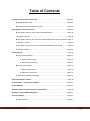
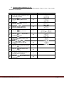
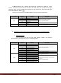
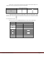
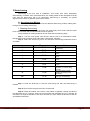
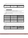
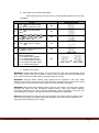
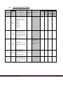
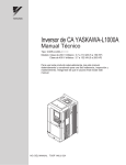
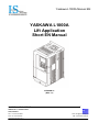
Yaskawa L1000A Manual EN YASKAWA L1000A Lift Application Short EN Manual VERSION V1 (REV 1.1) _ FACTORY - HEAD OFFICE: PERREVOU 37, THESSALONIKI 54352, GREECE TEL.: +30 231 220 9009 FAX.:+30 2310 943169 Copyright IS technology 2011 email: [email protected] URL: www.istechnology.gr Table of Contents 1) Digital Operator Panel JVOP-180 ........................................................................ Page 03 A. Digital Operator keys ................................................................................... Page 03 B. Example setting Parameters (C1-02)........................................................... Page 04 2) PG Option Cards Connection .............................................................................. Page 04 A. PG Option Cards for Asynchronous Geared Motors ................................... Page 06 1. Wiring the PG-X3.......................................................................................... Page 06 B. PG Option Cards for Synchronous Gearless PM Motors with Incremental . Page 17 1. Wiring the PG-X3.......................................................................................... Page 07 C. PG Option Card for Synchronous Gearless PM Motors with EnDat............ Page 09 1. Wiring the PG-F3 .......................................................................................... Page 09 3) Auto-tuning............................................................................................................ Page 11 A. Asynchronous Motors .................................................................................. Page 11 1. Rotating Auto-tuning........................................................................... Page 11 2. Stationary Auto-tuning ........................................................................ Page 12 B. Synchronous Motors .................................................................................... Page 13 1. Rotating Auto-tuning........................................................................... Page 13 2. Stationary Auto-tuning ........................................................................ Page 14 C. Auto-tuning Operation Example ................................................................... Page 15 4) User Parameters Tables....................................................................................... Page 18 5) Acceleration – Deceleration Ramps ................................................................... Page 44 6) Jerk Settings ......................................................................................................... Page 44 7) Brake sequence without torque compensation................................................. Page 45 8) Riding Comfort Related Problems ...................................................................... Page 47 9) Error Displays ....................................................................................................... Page 51 A. Fault Detection ............................................................................................. Page 51 Yaskawa L1000A Short Manual Page 2 1) Digital Operator Panel JVOP-180 You can set Inverter’s parameters or monitoring functions with the Digital operator panel, shown at Figure -1-. Figure -1Digital Operator Component Names and Functions A. Digital Operator keys Key Functions Key Name Function Key F1 Function Key F2 ESC Key RESET Key RUN Key Up Arrow Key Down Arrow Key STOP Key ENTER Key LO/RE Selection Key Function The functions assigned to F1 and F2 vary depending on the menu that is currently displayed. The name of each function appears in the lower half of the display window. • Returns to the previous display. • Moves the cursor one space to the left. • Pressing and holding this button will return to the Speed Reference display. • Moves the cursor to the right. • Resets the drive to clear a fault situation. Starts the drive in the LOCAL mode. The Run LED • is on, when the drive is operating the motor. • flashes during deceleration to stop or when the speed reference is 0. • flashes quickly the drive is disabled by a DI, the drive was stopped using an emergency stop DI or an up/down command was active during power up. Scrolls up to display the next item, selects parameter numbers and increments setting values. Scrolls down to display the next item, selects parameter numbers and increments setting values. Stops drive operation. • Enters parameter values and settings. • Selects a menu item to move between displays. Switches drive control between the operator (LOCAL) and the control circuit terminals (REMOTE). The LED is on when the drive is in the LOCAL mode (operation from keypad). RUN Light Lit while the drive is operating the motor. LO/RE Light Lit while the operator is selected to run the drive (LOCAL mode). Yaskawa L1000A Short Manual Page 3 B. Example setting parameter (C1-02). This example explains changing C1-02 (Deceleration Ramp 1) from 1.50 seconds (default) to 2.50 seconds. STEP Display/Result 1. Turn on the power to the drive. The initial display appears. ► 2. Press the or key until the Parameter Setting Mode screen appears. ► 3. Press the key to enter the parameter menu tree. ► 4. Press the or key to select the C parameter group. ► 5. Press the ► 6. Press the or key to select the parameter C1-02. ► Press the key to view the current setting value (1.50 s). Left digit flashes. Press , or until the desired number is selected. “1” flashes. ► Press the ► 7. 8. 9. key two times. key and enter 002.50. ► and the drive will confirm the change. ► 11. the screen shown in Step 4. The display automatically returns to ► 12. Press the ► 10. Press the initial display. Yaskawa L1000A Short Manual key until back at the ► Page 4 2) PG Option Cards Connection WARNING! Electrical Shock Hazard. Do not allow unqualified personnel to perform work on the drive. Failure to comply could result in death or serious injury. Maintenance, inspection, and replacement of parts must be performed only by authorized personnel familiar with installation, adjustment and maintenance of AC drives and Option Cards. NOTICE: Damage to Equipment. Observe proper electrostatic discharge procedures (ESD) when handling the option card, drive, and circuit boards. Failure to comply may result in ESD damage to circuitry. NOTICE: Damage to Equipment. Tighten all terminal screws to the specified tightening torque. Failure to comply may cause the application to operate incorrectly or damage the drive. Use the procedure described below when installing option cards to the drive. 1. Shut off power to the drive, wait the appropriate amount of time for voltage to dissipate, then remove the operator and front cover. 2. Insert the CN5 connector on the option card into the matching CN5 connector on the drive, then fasten it into place using one of the screws included with the option card. Yaskawa L1000A Short Manual Page 5 There are two types of PG Option Cards. One type for Gearless Synchronous Motors and Geared Asynchronous motors, PG-X3. And one type only for gearless synchronous motor, PG-F3. A. PG Option Card for asynchronous Geared Motors. 1. Wiring the PG-X3. This PG Option Card is used with three phases encoders. The terminal specifications for the PG-X3 are given in the following table: Terminal Block Terminal Function A+ AB+ BZ+ ZSD FE IP IG SG a+ ab+ bz+ z- ΤB1 ΤB2 Description A+ pulse signal input A– inverse pulse input • Inputs for the A, B, and Z pulses from the PG • Signal level matches RS-422 B+ pulse signal input B– inverse pulse input Z+ pulse signal input Z– inverse pulse input NC pin (open) Ground PG power supply PG power supply common Monitor signal common A pulse monitor signal A pulse inverse monitor signal B pulse monitor signal B pulse inverse monitor signal Z pulse monitor signal Z pulse inverse monitor signal For use when cables shields should not be grounded Used for grounding shielded lines • Output voltage: 12.0 V ± 5% or 5.5 V ± 5% • Max. output current: 200 mA • Output signal for monitoring A, B, and Z pulses from the PG • Signal level matches RS-422 Wiring Example for geared Asynchronous motor This example is use a LIKA i58H1024ZCU incremental encoder. First note the correspondence of cables and their colors. This correspondence is written on the encoder. For example, on the encoder is written: +12Vdc 0V A B Ā Red Black Yellow Green Blue B Orange Jumper CN3, on the PG-X3 card, determines the voltage for the PG power supply. The voltage level is set by the positioning the jumper as shown below. PG Power Supply Voltage (IP) Voltage Level 5.5 V 5% (default) 12.0 V 5% Jumper Yaskawa L1000A Short Manual Page 6 On Block terminal TB1 of PG-X3, the terminal A+ corresponds to phase A, so this terminal should be connected with the encoder’s YELLOW cable. The encoder power supply should be 12Vdc, and this voltage must selected from the jumper CN3. The jumper CN3 must . be on the position for 12Vdc The wiring of PG-X3 with LIKA i58H1024ZCU encoder is like the table below: Terminal Block ΤB1 ΤB2 Terminal A+ AB+ BFE IP IG Function Description YELLOW BLUE GREEN ORANGE SHIELD RED BLACK • Inputs for the A and B from the PG • Signal level matches RS-422 Used for grounding shielded lines • Output voltage: 12.0 V ± 5% or 5.5 V ± 5% • Max. output current: 200 mA B. PG Option Card for Synchronous Gearless Motors with Incremental Encoder. 1. Wiring the PG-X3. This PG Option Card is used with three phases encoders. The terminal specifications for the PG-X3 are given in the following table: Terminal Block ΤB1 ΤB2 Yaskawa L1000A Short Manual Terminal A+ AB+ BZ+ ZSD FE IP IG SG a+ ab+ bz+ z- Function Description A+ pulse signal input A– inverse pulse input B+ pulse signal input B– inverse pulse input Z+ pulse signal input Z– inverse pulse input NC pin (open) Ground PG power supply PG power supply common Monitor signal common A pulse monitor signal A pulse inverse monitor signal B pulse monitor signal B pulse inverse monitor signal Z pulse monitor signal Z pulse inverse monitor signal • Inputs for the A, B, and Z pulses from the PG • Signal level matches RS-422 For use when cables shields should not be grounded Used for grounding shielded lines • Output voltage: 12.0 V ± 5% or 5.5 V ± 5% • Max. output current: 200 mA • Output signal for monitoring A, B, and Z pulses from the PG • Signal level matches RS-422 Page 7 Wiring Example for gearless Synchronous motor with incremental This example is use a HEIDENHAIN ERN1321 incremental encoder. First note the correspondence of cables and their colors. This correspondence is written on the encoder manual. For example, on the encoder is written: +5Vdc 0V A B Z Ā Red Black Orange Brown Violet Yellow B Z blue Green Jumper CN3, on the PG-X3 card, determines the voltage for the PG power supply. The voltage level is set by the positioning the jumper as shown below. PG Power Supply Voltage (IP) Voltage Level 5.5 V 5% (default) 12.0 V 5% Jumper On Block terminal TB1 of PG-X3, the terminal A+ corresponds to phase A, so this terminal should be connected with the encoder’s ORANGE cable. The encoder power supply should be 5Vdc, and this voltage must selected from the jumper CN3. The jumper CN3 must be on the position for 5Vdc . The wiring of PG-X3 with HEIDENHAIN ERN1321 encoder is like the table below: Terminal Block ΤB1 ΤB2 Yaskawa L1000A Short Manual Terminal A+ AB+ BZ+ ZFE IP IG Function Description ORANGE YELLOW BROWN BLUE VIOLET GREEN SHIELD RED BLACK • Inputs for the A and B from the PG • Signal level matches RS-422 Used for grounding shielded lines • Output voltage: 12.0 V ± 5% or 5.5 V ± 5% • Max. output current: 200 mA Page 8 C. PG Option Card for Synchronous Gearless Motors with absolute EnDat encoder . 1. Wiring the PG-F3. This PG Option Card is used with three phases encoders. The terminal specifications for the PG-F3 are given in the following table: Terminal Block Terminal IP Description IG Encoder power supply common DT Comm. Data signal I/O Inverse comm. data signal I/O B+ B pulse signal input B– Inverse B pulse signal input b+ B pulse monitor signal output Inverse B pulse monitor signal output b– IP IG CK Encoder power supply Encoder power supply common Comm. Clock signal output Inverse comm. clock signal Output A pulse signal input A+ A– Inverse A pulse signal input a+ A pulse monitor signal output Supplies power to the encoder. Reads and processes encoder data. Signal level: RS-485 protocol Input for the B pulse sinewave from the encoder. FE • Max. input frequency: 50 kHz • Input signal differential: B+ - B– • Output method: Line driver • Output voltage: RS-422 level • Possible resolution: 1/n Set F1-06 to monitor the pulse signal. Varies by drive models. Outputs a ratio of the B pulse frequency. Supplies power to the encoder. Connects to terminal IP on the option card. Connects to terminal IG on the option card. Signal level: RS-485 protocol Outputs the comm. clock signal to the encoder Input for the A pulse sinewave from the encoder. Outputs a ratio of the A pulse frequency. Inverse A pulse monitor signal Output Ground a– Specifications • Jumper with terminal CN3 to select the power supply voltage, 8 V or 5 V. • Voltage range: 5 V ±5%, 330 mA 8 V ±10%, 150 mA Note: Number of connections to terminals IP and IG differs by wiring length when the power supply is set for +5 V ±5%. • Up to 10 m: One or two connections to both IP and IG. • 10 to 20 m: Two connections to both IP and IG. Encoder power supply ΤB1 ΤB2 Function Ground terminal for shielded cable. • Max. input frequency: 50 kHz • Input signal differential: A+ - A– • Output method: Line driver • Output voltage: RS-422 level • Possible resolution ratio: 1/n Set F1-06 to monitor the pulse signal. Varies by drive models. Used for grounding shielded line. Wiring Example for gearless Synchronous motor with Absolute EnDat encoder. This example is use a HEIDENHAIN ECN413 EnDat encoder. First note the correspondence of cables and their colors. This correspondence is written on the encoder manual. For example, on the encoder is written: Up Sensor Up 0V Brown/Green Blue White/Green Sensor CLOCK 0V White Yaskawa L1000A Short Manual Purple DATA Yellow Gray Pink A+ A– B+ B– Green/Black Yellow/Black Blue/Black Red/Black Page 9 Jumper CN3, on the PG-X3 card, determines the voltage for the PG power supply. The voltage level is set by the positioning the jumper as shown below. PG Power Supply Voltage (IP) Voltage Level 5.0 V 5% (default) 8.0 V 5% Jumper On Block terminal TB1 of PG-X3, the terminal DT corresponds to DATA signal, so this terminal should be connected with the encoder’s GRAY cable. The encoder power supply should be 5Vdc, and this voltage must selected from the jumper CN3. The jumper CN3 must be on the position for 5Vdc . The wiring of PG-X3 with HEIDENHAIN ERN1321 encoder is like the table below: Option Card Terminal IP IG CK Encoder Cable Color Encoder Side Brown/Green Up Blue Sensor Up White/Green 0V White Sensor 0V Purple CLOCK Yellow DT Gray DATA Pink A+ Green/Black A+ A– Yellow/Black A– B+ Blue/Black B+ B– Red/Black B– Yaskawa L1000A Short Manual Page 10 3) Auto-tuning Auto-tuning is the first step of installation. This mode, sets motor parameters automatically. Therefore some motor data which are usually written at the nameplate must be input and the Auto-tuning has to be performed. Auto-tuning is necessary for geared asynchronous motors or gearless synchronous motors. A. Asynchronous Motors For asynchronous motors, one can use two different Auto-tuning modes, rotating autotuning and non-rotating auto-tuning. 1. Rotating Auto-tuning Use this tuning mode only, if the motor can rotate freely which means that the ropes have to be removed and mechanical brake must be opened. The procedure for rotating autotune can be made with the following steps. Step 1. Turn the main power ON. Be sure that the lift is on maintenance Mode. Energize the motor contactor K6 and the brake contactor K9, manually. Step 2. Select the Auto-tuning menu and set Motor Auto-tuning Parameters as the next table: 1. 2. 3. Parameter T1-01 T1-02 T1-03 4. T1-04 5. 6. 7. T1-05 T1-06 T1-07 8. T1-08 9. T1-09 10. T1-10 Value 0: Set T1-01 to 0 for rotating Auto-tuning. Motor output power in kilowatts. Set the rated voltage of the motor. Set the rated current of the motor. Set the rated frequency of the motor. Set the number of motor poles. Set the base speed of the motor in rpm. Set the number of PG pulses per revolution, in case of using encoder. No load current of motor. Usually this setting is not necessary. Motor Rated slip. Usually this setting is not necessary. Step 3. Press the RUN key to start the auto-tuning and wait until auto-tuning is finished. Step 4. Open the de-energize the motor contactor K6. Step 5. Check the rotation of the motor. If the rotation is opposite, change the value of the parameter b1-14. If using a close loop control mode and parameter b1-14 is changed, be sure also to change the direction of the motor encoder (F1-05) to match the direction of the UP and DOWN commands. Yaskawa L1000A Short Manual Page 11 2. Stationary Auto-tuning Use this tuning mode only, if the motor cannot rotate freely which means that the ropes cannot be removed and mechanical brake must be closed. The procedure for stationary auto-tuning can be made with the following steps. Step 1. Turn the main power ON. Be sure that the lift is on maintenance Mode. Energize the motor contactor K6 manually. Step 2. Select the Auto-tuning menu and set Motor Auto-tuning Parameters as the next table: 1. 2. 3. Parameter T1-01 T1-02 T1-03 4. T1-04 5. 6. 7. T1-05 T1-06 T1-07 8. T1-08 9. T1-09 10. T1-10 Value 1: Set T1-01 to 1 for Stationary Auto-tuning 2. Motor output power in kilowatts. Set the rated voltage of the motor. Set the rated current of the motor. Set the rated frequency of the motor. Set the number of motor poles. Set the base speed of the motor in rpm. Set the number of PG pulses per revolution, in case of using encoder. No load current of motor. Usually this setting is not necessary. Motor Rated slip. Usually this setting is not necessary. Step 3. Press the RUN key to start the auto-tuning and wait until auto-tuning is finished. Step 4. Open the de-energize the motor contactor K6. Step 5. Check the rotation of the motor. If the rotation is opposite, change the value of the parameter b1-14. If using a close loop control mode and parameter b1-14 is changed, be sure also to change the direction of the motor encoder (F1-05) to match the direction of the UP and DOWN commands. Yaskawa L1000A Short Manual Page 12 B. Synchronous Motors For synchronous motors, one can use two different Auto-tuning modes, rotating autotuning and non-rotating auto-tuning. Also we can use absolute or incremental encoders. 1. Rotating Auto-tuning Use this tuning mode only, if the motor can rotate freely which means that the ropes have to be removed and mechanical brake must be opened and EnDat encoder is used. The procedure for rotating autotune can be made with the following steps. Step 1. Turn the main power ON. Be sure that the lift is on maintenance Mode. Energize the motor contactor K6 manually. Step 2. Select the Auto-tuning menu and set Motor Auto-tuning Parameters as the next table: 1. 2. 3. 4. Parameter T2-01 T2-04 T2-05 5. 6. T2-06 T2-08 T2-09 7. T2-16 Value 1: Set T2-01 to 1 for stationary Auto-tuning. Motor output power in kilowatts. Set the rated voltage of the motor. Set the rated current of the motor. Set the number of motor poles. Set the base speed of the motor in rpm. Set the number of PG pulses per revolution, in case of using encoder. Step 3. Press the RUN key to start the auto-tuning and wait until auto-tuning is finished. Step 5. Select the Auto-tuning menu and set Motor Auto-tuning Parameters as the next table: 1. Parameter Value T2-01 3: Set T2-01 to 3 for Initial Magnet Pole Search Parameter Auto-tuning Step 6. Press the RUN key to start the auto-tuning and wait until auto-tuning is finished. Step 7. Select the Auto-tuning menu and set Motor Auto-tuning Parameters as the next table: Parameter 1. T2-01 Value 10: Set T2-01 to 10 for Rotational Encoder Offset Auto-tuning. Step 8. Press the RUN key to start the auto-tuning and wait until auto-tuning is finished. Yaskawa L1000A Short Manual Page 13 Step 9. Select the Auto-tuning menu and set Motor Auto-tuning Parameters as the next table: Parameter 1. T2-01 Value 11: Set T2-01 to 11 for Rotational Back EMF Constant Auto-tuning. Step 10. Press the RUN key to start the auto-tuning and wait until auto-tuning is finished. 2. Stationary Auto-tuning Use this tuning mode only, if the motor can not rotate freely which means that the ropes can not be removed and mechanical brake must be closed. The procedure for stationary autotuning can be made with the following steps Step 1. Turn the main power ON. Be sure that the lift is on maintenance Mode. Energize the motor contactor K6 manually. Step 2. Select the Auto-tuning menu and set Motor Auto-tuning Parameters as the next table: 1. 2. 3. 4. Parameter T2-01 T2-04 T2-05 5. 6. T2-06 T2-08 T2-09 7. T2-16 Value 1: Set T2-01 to 1 for stationary Auto-tuning. Motor output power in kilowatts. Set the rated voltage of the motor. Set the rated current of the motor. Set the number of motor poles. Set the base speed of the motor in rpm. Set the number of PG pulses per revolution, in case of using encoder. Step 3. Press the RUN key to start the auto-tuning and wait until auto-tuning is finished. Step 5. Select the Auto-tuning menu and set Motor Auto-tuning Parameters as the next table: 1. Parameter T2-01 2. T2-06 Value 2: Set T2-01 to 2 for Stationary Stator Resistance Auto-tuning. Set the rated current of the motor. Step 6. Press the RUN key to start the auto-tuning and wait until auto-tuning is finished. Yaskawa L1000A Short Manual Page 14 Step 7. Select the Auto-tuning menu and set Motor Auto-tuning Parameters as the next table: Parameter Value T2-01 3: Set T2-01 to 3 for Initial Magnet pole search Parameters Auto-tuning. 1. Step 8. Press the RUN key to start the auto-tuning and wait until auto-tuning is finished. If the error “Er22” appears, then check the follow steps: a. If case of using absolute encoder, remove the ropes from the motor, energize manually the brake contactor, and select the Rotational Encoder Offset Auto-tuning T2-10=10 b. In case of using incremental encoder, change the PG option card and use an absolute encoder. And repeat the Auto-tuning procedure from step 7. Step 9. Select the Auto-tuning menu and set Motor Auto-tuning Parameters as the next table: Parameter T2-01 1. Value 4: Set T2-01 to 4 for Stationary Encoder Offset Auto-tuning. Step 10. Press the RUN key to start the auto-tuning and wait until auto-tuning is finished. C. Auto-Tuning Operation Example The following example demonstrates Rotational Auto-Tuning when using Open Loop Vector Control (A1-02 = 2). a) Selecting the type of Auto-tuning STEP Display/Result 1. Turn on the power to the drive. The initial display appears. ► 2. Press the or key until the Auto-Tuning display appears. ► 3. Press to begin setting parameters. ► 4. Press T1-01. ► 5. Save the setting by pressing 6. The display automatically returns to the display shown in Step 3. to select the value for Yaskawa L1000A Short Manual . ► ► Page 15 b) Enter Data from the Motor Nameplate After selecting the type of Auto-Tuning, enter the data required from the motor nameplate. STEP Display/Result 1. Press to access the motor output power parameter T1-02. ► 2. Press setting. ► 3. Press , , , and to enter the motor power nameplate data in kW. ► 4. Press ► 5. The display automatically returns to the display in Step 1. ► 6. Repeat Steps 1 through 5 to set the following parameters: • T1-03, Motor Rated Voltage • T1-04, Motor Rated Current • T1-05, Motor Base Frequency • T1-06, Number of Motor Poles • T1-07, Motor Base Speed ► to view the default to save the setting. ► c) Starting Auto-Tuning WARNING! Sudden Movement Hazard. The drive and motor may start unexpectedly during Auto-Tuning, which could result in death or serious injury. Ensure the areas surrounding the drive, motor and load are clear before proceeding with Auto-Tuning. WARNING! Electrical Shock Hazard. High voltage will be supplied to the motor when Stationary Auto-Tuning is performed even with the motor stopped, which could result in death or serious injury. Do not touch the motor until Auto-Tuning has been completed. WARNING! When performing Rotational Auto-Tuning for motor data or encoder offset, always uncouple the motor from the mechanical system (remove ropes from traction sheave). Performing Rotational Auto-Tuning with the mechanical system connected to the motor can cause hazardous situations, injury to personnel and damage to the equipment. NOTICE: Rotational Auto-Tuning will not function properly if a holding brake is applied on the load. Failure to comply could result in improper operation of the drive. Ensure the motor can freely spin before beginning Auto-Tuning. Yaskawa L1000A Short Manual Page 16 Enter the required information from the motor nameplate. Press to proceed to the Auto-Tuning start display. STEP Display/Result 1. After entering the data listed on the to motor nameplate, press confirm. ► 2. Press to activate Auto-Tuning. The drive begins by injecting current into the motor for about 1 min, and then starts to rotate the motor. ► 3. Auto-Tuning finishes in approximately one to two minutes. ► Yaskawa L1000A Short Manual Page 17 4) User Parameters Tables Name Parameter Number A1-00 A1-01 A1-02 Display Control Methods Description Setting Range IS Technology Factory Setting V/f Open Loop Vector Closed Loop Display Vector Closed Loop Display Vector PM Motor Language Selection Used to select the language displayed on the Digital Operator (JVOP-180 only). 0: English 1: Japanese 2: German 3: French 4: Italian 5: Spanish 6: Portuguese 7:Chinese 0 to 7 0 A A A A Access Level Selection 0: View and set A1-01 and A1-04. U□-□□ parameters can also be viewed. 1: User Parameters (access to a set of parameters selected by the user, A2-01 to A2-32) 2: Advanced Access (access to view and set all parameters) 0 to 2 2 A A A A Q Q Q Q Control method selection A1-03 Initialize Parameters A1-04 Password 0: V/f control 2: Open-loop vector control 3: Closed-loop vector control 7: Closed-loop vector control (PM) 0: No initialization 1110: User Initialize (parameter values must be stored using parameter o203) 2220: 2-wire initialization. 5550:oPE04 error reset When the value set into A104 does not match the value set into A1-05, parameters A1-01 through A1-03, and A2-01 through A2-33 cannot be changed. Yaskawa L1000A Short Manual 0 to 7 2: for Open-loop vector 1 control 3: Closed- loop vector control 7: Closed- loop vector control (PM) 0 to 5550 0 A A A A 0 to 9999 0 A A A A Page 18 Control Methods Parameter Number Display b1-01 Speed Reference Selection b1-02 Up/Down Command Selection b1-03 Stopping Method Selection b1-06 Digital Input Reading b1-08 Up/Down Command Selection while in Programming Mode b1-14 Phase Order Selection b2-08 Magnetic Flux Compensation Value b4-01 b4-02 b6-01 b6-02 b6-03 b6-04 Timer Function OnDelay Time Timer Function OffDelay Time Dwell Speed at Start Dwell Time at Start Dwell Speed at Stop Dwell Time at Stop b7-01 Droop Control Gain b7-02 Droop Control Delay Time Description 0: Digital operator 1: Analog input terminals 2: MEMOBUS/Modbus communications 3: Option card 0: Digital operator 1: Digital input terminals 2: MEMOBUS/Modbus communications 3: Option card 0: Ramp to stop 1: Coast to stop 0: Input status is read once and processed immediately (for quick response) 1: Input is read twice and processed only if the status is the same in both readings (robust against noisy signals) 0: Up/Down command not accepted while in the Programming Mode. 1: Up/Down command accepted while in the Programming Mode. 2: Prohibit entering Programming Mode during run. 0: U-V-W 1: U-W-V Sets the magnetic flux compensation as a percentage of the no-load current value (E2-03). Used to set the on-delay and off-delay times for a digital timer output (H2-□□=12). The output is triggered by a digital input programmed to H1-□□=18) Parameters b6-01 and b6-02 set the speed to hold and the time to maintain that speed at start. Parameters b6-03 and b6-04 set the speed to hold and the time to maintain that speed at stop. Sets the speed reduction gain applied at a torque reference of 100%. Set as a percentage of motor base speed. Used to adjust the responsiveness of Droop Control. Yaskawa L1000A Short Manual Setting Range IS Technology Factory Setting V/f Open Loop Vector Closed Loop Display Vector Closed Loop Display Vector PM Motor 0 to 3 0 A A A A 0 to 3 1 A A A A 0 to 1 0 A A A A 0 to 1 1 A A A A 0 to 2 1 A A A A 0 to 1 0 A A A A 0% to 1000% 0 No A No No 0.0s to 3000.0s 0 A A A A 0.0s to 3000.0s 0.5–0.7s A A A A 0% A A A A 0s A A A A 0% A A A A 0s A A A A 0.0% to 100.0% No No No A 0.03s to 2.00s No No No A 0.0% to 100.0% 0.0s to 10.0s 0.0% to 100.0% 0.0s to 10.0s Page 19 Control Methods Parameter Number b8-01 b8-16 b8-17 C1-01 C1-02 C1-03 C1-04 C1-05 C1-06 C1-07 C1-08 C1-09 C1-10 C1-11 C1-15 V/f Open Loop Vector Closed Loop Display Vector Closed Loop Display Vector PM Motor 0 No No No A 0.00 to 2.00 0.10 No No No A 0.00 to 2.00 1.00 No No No A 0.00s to 600.00s 1.80 s A A A A 0 to 1 0 A A A A Sets the speed to switch between accel/decel ramp settings. 0.0% to 100.0% 0.0% A A A A Sets the deceleration ramp used for inspection run. 0.00s to 2.00s 0.00s A A A A Display Energy Saving Control Selection Energy Saving Control Constant (Ki) Energy Saving Control Constant (Kt) Acceleration Ramp 1 Deceleration Ramp 1 Acceleration Ramp 2 Deceleration Ramp 2 Acceleration Ramp 3 Deceleration Ramp 3 Acceleration Ramp 4 Deceleration Ramp 4 Emergency Stop Ramp Accel/Decel Setting Resolution Accel/Decel Switching Speed Inspection Deceleration Ramp Description 0: Disabled 1: Enabled Enter the Energy Saving value (Ki) as specified on the motor name plate. (for IPM motors only) Enter the Energy Saving value (Kt) as specified on the motor name plate. (for IPM motors only) Sets the ramp to accelerate from 0 to maximum speed. Sets the ramp to decelerate from maximum speed to 0. Sets the ramp to accelerate from 0 to maximum speed. Sets the ramp to decelerate from maximum speed to 0. Sets the ramp to accelerate from 0 to maximum speed. Sets the ramp to decelerate from maximum speed to 0. Sets the ramp to accelerate from 0 to maximum speed. Sets the ramp to decelerate from maximum speed to 0. Sets the ramp for the Emergency Stop function. 0: 0.01 s unit 1: 0.1 s unit Yaskawa L1000A Short Manual Setting Range IS Technology Factory Setting 0 to 1 Page 20 Control Methods Parameter Number C2-01 C2-02 C2-03 C2-04 C2-05 C3-01 C3-02 Display Jerk at Accel Start Jerk at Accel End Jerk at Decel Start Jerk at Decel End Jerk below Leveling Speed Slip Compensation Gain Slip Compensation Primary Delay Time Description Setting Range Five different jerk values can be set. They are automatically applied as shown in the figure below. 0.0s to 10.00s 0.0s to 10.00s 0.0s to 10.00s 0.0s to 10.00s V/f Open Loop Vector Closed Loop Display Vector Closed Loop Display Vector PM Motor 0.5s A A A A 0.5s A A A A 0.5s A A A A 0.5s A A A A IS Technology Factory Setting Sets the jerk used when the speed reference is lower than the leveling speed setting 0.0s to 10.00s 0.5s A A A A Sets the gain for the motor slip compensation function. 0.0 to 2.5 1.0 No A A No Adjusts the slip compensation function delay time. 0ms to 10000ms 0ms No A No No C3-03 Slip Compensation Limit Sets an upper limit for the slip compensation function as a percentage of motor rated slip for motor 1 (E2-02). 0% to 250% 0% No A No No C3-04 Slip Compensation Selection during Regeneration 0: Disabled. 1: Enabled above 6 Hz. 2: Enabled whenever slip compensation is possible. 0 to 2 0 No A No No C3-05 Output Voltage Limit Operation Selection 0 to 1 1 No A A A C4-01 Torque Compensation Gain 0.00 to 2.50 1 A A No No Sets the torque compensation filter time. 0ms to 60000ms 0ms No A No No Sets torque compensation at forward start as a percentage of motor torque. 0.0% to 200.0% 100% No A No No Sets torque compensation at reverse start as a percentage of motor torque. 0.0% to 200.0% -100% No A No No Sets the time constant for torque compensation at forward start and reverse start (C4-03 and C404). 0ms to 200ms 10ms No A No No C4-02 C4-03 C4-04 C4-05 Torque Compensation Primary Delay Time Torque Compensation at Forward Start Torque Compensation at Reverse Start Torque Compensation Time Constant 0: Disabled. 1: Enabled. Automatically decreases motor flux when output voltage saturation is reached. Sets the gain for the automatic torque (voltage) boost function and helps to produce better starting torque. Yaskawa L1000A Short Manual Page 21 Control Methods Parameter Number Display C5-01 Speed Control Loop Proportional Gain 1 Speed Control Loop Integral Time 1 Speed Control Loop Proportional Gain 2 Speed Control Loop Integral Time 2 Speed Control Loop Primary Delay Time Constant Speed Control Settings Switching Speed Speed Control Loop Integral Limit Speed Control Loop Proportional Gain 3 Speed Control Loop Integral Time 3 Speed Control Loop Delay Time during Position Lock Speed Control Loop Proportional Gain Time during Position Lock Speed Control Loop Integral Time during Position Lock C5-02 C5-03 C5-04 C5-06 C5-07 C5-08 C5-13 C5-14 C5-16 C5-19 C5-20 Description Setting Range IS Technology FactorySetting V/f Open Loop Vector Closed Loop Display Vector Closed Loop Display Vector PM Motor Sets the proportional gain 1 of the speed control loop. 0 to 300 determined by the control mode (A102). No No A A Sets the integral time 1 of the speed control loop. 0s to 10.0s determined by the control mode (A102). No No A A Sets the proportional gain 2 of the speed control loop. 0 to 300 determined by the control mode (A102). No No A A Sets the integral time 2 of the speed control loop. 0s to 10.0s determined by the control mode (A102). No No A A Sets the filter time constant for the time from the speed loop to the torque command output. 0.0s to 0.5s No No A A Sets the speed for switching between proportional gain 1, 2, 3 and integral time 1, 2, 3. 0% to 100% No No A A Sets the speed control loop integral upper limit as a percentage of rated torque. 0% to 400% No No A A Sets the proportional gain 3 of the speed control loop. 0 to 300 determined by the control mode (A102). No No A A Sets the integral time 3 of the speed control loop. 0s to 10.0s determined by the control mode (A102). No No A A Sets a delay to the torque command output from speed control loop during position lock. 0s to 0.5s No No A A Sets the Speed Control Loop Proportional gain used during Position Lock 0 to 300 No No A A Sets the Speed Control Loop Integral time used during Position Lock. 0s to 10.0s No No A A Yaskawa L1000A Short Manual 0.004s determined by the control mode (A102). 400% 0.0s determined by the control mode (A102). 0.1s Page 22 Control Methods Parameter Number C6-03 C6-06 C6-09 C6-21 C6-23 Display Description Setting Range IS Technology Factory Setting V/f Open Loop Vector Closed Loop Display Vector Closed Loop Display Vector PM Motor A A A A Carrier Frequency Sets the carrier frequency. 1.0kHz to 15.0kHz Determined by o2-04 PWM Method Selects PWM modulation method. 0: 2-phase/3-phase conversion 1: 2-phase modulation 2: 3-phase modulation 0 to 2 2 A A A A 0: Carrier Frequency = 5 kHz 1: Setting value for C6-03 0 to 1 0 No A A A Sets the carrier frequency during Inspection Run. 0: Setting value for C6-03 1: Carrier Frequency = 2 kHz 0 to 1 1 A A A A Sets the carrier frequency when estimating the initial polarity. 0: Carrier Frequency = 2 kHz 1: Setting value for C6-03 0 to 1 0 A A A A Carrier Frequency during Rotational AutoTuning Inspection Operation Carrier Frequency Carrier Frequency during Initial Motor Pole Search Yaskawa L1000A Short Manual Page 23 Control Methods Parameter Number Display d1-01 d1-02 d1-03 d1-04 d1-05 d1-06 d1-07 d1-08 Speed Reference 1 Speed Reference 2 Speed Reference 3 Speed Reference 4 Speed Reference 5 Speed Reference 6 Speed Reference 7 Speed Reference 8 Sets the Speed reference for the drive when d1-18 is set to 0 or 3. Setting units are determined by parameter o1-03. 0.0% to 100.0% Speed Reference Selection Mode Sets the mode of speed reference selection by digital inputs. 0: Use multi-speed references (d1-01 to d1-08) 1: High speed reference has priority (d1-19 to d1-23, d1-26) 2: Leveling speed reference has priority (d1-19 to d1-23, d1-26) 3: Use multi-speed references d1-02 to d1-08, no speed selection stops the drive. Drive will stop when all input terminals programmed for speed references (H1-□□= 3, 4, 5) are open. 0 to 3 d1-18 Description Sets the nominal speed reference when d1-18 = 1 or 2. d1-19 Nominal Speed d1-20 Intermediate Speed 1 Sets intermediate speed reference 1 when d1-18 = 1 or 2. d1-21 Intermediate Speed 2 Sets intermediate speed reference 2 when d1-18 = 1 or 2. d1-22 Intermediate Speed 3 Sets intermediate speed reference 3 when d1-18 = 1 or 3. d1-23 Releveling Speed Sets speed reference for releveling when d1-18 = 1 or 2. d1-24 Inspection Operation Speed Sets speed reference when inspection operation is enabled. d1-25 Rescue Operation Speed Sets the speed reference during inspection operation. d1-26 Leveling Speed Sets leveling speed reference when d1-18 = 1 or 2. Yaskawa L1000A Short Manual Setting Range 0.0% to 100.0% (PM) 0.0Hz to 50.0Hz 0.0% to 100.0% (PM) 0.0Hz to 50.0Hz 0.0% to 100.0% (PM) 0.0Hz to 50.0Hz 0.0% to 100.0% (PM) 0.0Hz to 50.0Hz 0.0% to 100.0% (PM) 0.0Hz to 50.0Hz 0.0% to 100.0% (PM) 0.0Hz to 50.0Hz 0.0% to 100.0% (PM) 0.0Hz to 50.0Hz 0.0% to 100.0% (PM) 0.0Hz to 50.0Hz V/f Open Loop Vector Closed Loop Display Vector Closed Loop Display Vector PM Motor A A A A A A A A A A A A A A A A A A A A A A A A A A A A 15% A A A A 8% A A A A 8% A A A A IS Technology Factory Setting 0% 100% 15% 0% 8% 0% 0% 0% 3 Page 24 Control Methods Parameter Number d1-28 d1-29 d6-03 d6-06 Display Leveling Speed Detection Level Inspection Speed Detection Level Field Forcing Selection Field Forcing Limit Description Used when d1-18 = 0 or 3. If the speed reference selected is lower than d1-28, then the drive uses the leveling speed as the speed reference. Used when d1-18 = 0 or 3. If the speed reference selected is higher than d1-28 but lower or equal to d1-29, then the drive uses inspection speed as the speed reference. Setting Range 0.0% to 100.0% (PM) Closed Loop Display Vector Closed Loop Display Vector PM Motor 10% A A A A 20% A A A A 0 No A A No No A A No 0.0Hz to 50.0Hz d1-28 to 100.0% (PM) d1-28 to 50.0Hz 0: Disabled 1: Enabled 0 to 1 Sets the upper limit of the excitation current command during magnetic field forcing. A setting of 100% is equal to motor no-load current. Disabled only during DC Injection Braking. 100% to 400% Yaskawa L1000A Short Manual V/f Open Loop Vector IS Technology Factory Setting 400% Page 25 Control Methods Parameter Number Display E1-01 Input Voltage Setting E1-03 V/f Pattern Selection E1-04 E1-05 E1-06 E1-07 E1-08 E1-09 E1-10 E1-11 E1-12 E1-13 Maximum Output Frequency Maximum Voltage Base Frequency Middle Output Frequency Middle Output Frequency Voltage Minimum Output Frequency Minimum Output Frequency Voltage Middle Output Frequency 2 Middle Output Frequency Voltage 2 Base Voltage Description This parameter must be set to the power supply voltage. WARNING! Drive input voltage (not motor voltage) must be set in E1-01 for the protective features of the drive to function properly. Failure to do so may result in equipment damage and/ or death or personal injury. F: Custom V/f, E1-04 through E1-13 settings define the V/f pattern To set linear V/f characteristics, set the same values for E1-07 and E1-09. In this case, the setting for E1-08 will be disregarded. Ensure that the four frequencies are set according to these rules: E1-09≤E1-07E1-06≤E111≤E1-04 Note that if E1-11 = 0, then both E1-11 and E1-12 are disabled, and the above conditions do not apply. V/f Open Loop Vector Closed Loop Display Vector Closed Loop Display Vector PM Motor 400V A A A A F A No No No A A A A Setting Range IS Technology Factory Setting 155V to 400V F 50Hz 50Hz Note: Some parameters may not be available depending on the control mode. • E1-07, E1-08 and E-10 are available only in the V/f control and Open Loop Vector control modes. • E1-11, E1-12 and E-13 are available only in the V/f control and Closed Loop Vector control modes. Yaskawa L1000A Short Manual Page 26 Control Methods Parameter Number E2-01 Motor Rated Current E2-02 Motor Rated Slip E2-03 E2-04 E2-05 E2-06 E2-07 E2-08 E2-09 E2-10 E2-11 V/f Open Loop Vector Closed Loop Display Vector Closed Loop Display Vector PM Motor A A A A No 0.0Hz to 20.0Hz Hz A A A No 0A to E2-01 A A A A No 2 to 48 4 A A A No 0.0Ω to 65.0Ω A A A No 0.0% to 40.0% A A A No Sets the motor iron saturation coefficient at 50% of magnetic flux. Automatically set during Auto-Tuning. 0.0 to 0.50 No A A No Sets the motor iron saturation coefficient at 75% of magnetic flux. Automatically set during Auto-Tuning. E2-07 to 0.75 No A A No Sets the motor mechanical loss as a percentage of motor rated power (kW). 0.0% to 10.0% No A A No Sets the motor iron loss. 0W to 65535W A No No No Sets the motor rated power in kilowatts (1 HP = 0.746 kW). Automatically set during Auto-Tuning. 0.0kW to 650.0kW A A A No Display Motor NoLoad Current Number of Motor Poles Motor Line-toLine Resistance Motor Leakage Inductance Motor Iron-Core Saturation Coefficient 1 Motor Iron-Core Saturation Coefficient 2 Motor Mechanica l Loss Motor Iron Loss for Torque Compensat ion Motor Rated Power Description Sets the motor nameplate full load current in Amps. Automatically set during Auto-Tuning. Sets the motor rated slip. Automatically set during Auto-Tuning. Sets the no-load current for the motor. Automatically set during Auto-Tuning. Sets the number of motor poles. Automatically set during Auto-Tuning. Sets the phase-to-phase motor resistance. Automatically set during Auto-Tuning. Sets the voltage drop due to motor leakage inductance as a percentage of motor rated voltage. Automatically set during Auto-Tuning. Yaskawa L1000A Short Manual Setting Range IS Technology Factory Setting KW Page 27 Control Methods Parameter Number E5-02 E5-03 E5-04 E5-05 E5-06 E5-07 Display Motor Rated Power Motor Rated Current Motor Poles Motor Stator Resistance (Single Phase) Motor dAxis Inductance Motor qAxis Inductance E5-09 Motor Induction Voltage Constant 1 E5-11 Encoder Offset E5-24 Motor Induction Voltage Constant 2 Description Setting Range Sets the rated capacity of the motor. 0.1kW to 650kW Sets the motor rated current. IS Technology Factory Setting V/f Open Loop Vector Closed Loop Display Vector Closed Loop Display Vector PM Motor No No No A No No No A Sets the number of motor poles. 2 to 48 No No No A Sets the stator resistance (1 phase value). 0.0Ω to 65.0Ω No No No A Sets the d-axis inductance. 0.0mH to 600.0mH No No No A Sets the q-axis inductance. 0.0mH to 600.0mH No No No A 0.0mV to 6500.0m V No No No A -180o to 180o No No No A 0.0mV to 6500.0 mV No No No A Sets the induced phase peak voltage in units of 0.1 mV (rad/s) [electrical angle]. When setting this parameter, E5-24 should be set to 0.0. Sets the offset between the rotor magnetic axis and the encoder zero position. Set during Encoder Offset Tuning. Sets the induced phase-tophase rms voltage in units of 0.1 mV/(r/min) [mechanical angle]. When setting this parameter, E5-24 should be set to 0.0. Yaskawa L1000A Short Manual Page 28 Control Methods Parameter Number F1-01 Encoder 1 Resolution F1-02 Operation Selection at PG Open Circuit (PGo) F1-03 Operation Selection at Overspeed (oS) F1-04 Operation Selection at Deviation F1-05 Encoder 1 Rotation Direction Selection F1-06 F1-08 F1-09 F1-10 F1-11 F1-14 V/f Open Loop Vector Closed Loop Display Vector Closed Loop Display Vector PM Motor Pulses/Rev olution No No A A 0 to 3 1 No No A A 0 to 3 1 No No A A 0 to 3 3 No No A A 0 to 1 0 No No A A 1 to 132 1 No No A A 0% to 120% 115% No No A A 0.0s 2.0s 0.0s No No A A Sets the speed deviation detection level as a percentage of the maximum output frequency. 0% to 50% 10% No No A A Sets the time in seconds for a speed deviation situation to trigger a fault (dEv). 0.0s to 10.0s 0.5s No No A A Sets the time required to trigger a PG Open fault (PGo). 0.0s to 10.0s 2.0s No No A A 0 to 10 10 No No No A 0 5000 128 No No No A Display PG 1 Pulse Monitor Output Division Ratio Overspeed Detection Level Overspeed Detection Delay Time Excessive Speed Deviation Detection Level Excessive Speed Deviation Detection Delay Time PG OpenCircuit Detection Time F1-18 dv3 Detection Selection F1-19 dv4 Detection Selection Description Sets the encoder resolution (number of pulses per revolution) 0: Ramp to stop. Decelerate to stop using the deceleration ramp in C1-02. 1: Coast to stop. 2: Emergency Stop. Decelerate to stop using the deceleration ramp in C1-09. 3: Alarm only. 0: Ramp to stop. Decelerate to stop using the deceleration ramp in C1-02. 1: Coast to stop. 2: Emergency Stop. Decelerate to stop using the deceleration ramp in C1-09. 3: Alarm only. 0: Ramp to stop. Decelerate to stop using the deceleration ramp in C1-02. 1: Coast to stop. 2: Emergency Stop. Decelerate to stop using the deceleration ramp in C1-09. 3: Alarm only. 0: A phase leads B in up direction 1: B phase leads A in up direction Sets the division ratio for the pulse monitor used of the PG option card installed to connector CN5-C. By setting “xyz”, the division ratio becomes = [(1 + x) / yz]. If only using the A pulse for one track input, then the input ratio will be 1:1, regardless of what F1-06 is set to. Sets the overspeed detection level as a percentage of the maximum output frequency. Sets the time in seconds for an overspeed situation to trigger a fault (oS). 0: Disabled n: Sets the number of dv3 situations that may be detected before triggering an actual dv3 fault. 0: Disabled n: Number of pulses that the A and B pulse are reversed that triggers dv4 detection. Yaskawa L1000A Short Manual Setting Range IS Technology Factory Setting 1 to 60000 Page 29 Control Methods Parameter Number F1-20 F1-29 F1-51 F1-63 H1-03 H1-04 H1-05 H1-06 H1-07 H1-08 H2-01 H2-02 H2-03 H2-04 H2-05 Display PG Option Card Disconnect Detection 1 dEv Detection Condition Selection PGoH Detection Level PG-E3 R Track Selection Terminal S3 Function Selection Terminal S4 Function Selection Terminal S5 Function Selection Terminal S6 Function Selection Terminal S7 Function Selection Terminal S8 Function Selection Terminals M1-M2 Function Selection (relay) Terminals M3-M4 Function Selection (relay) Terminals M5-M6 Function Selection (relay) Terminal P1C1 Function Selection (photocoupler ) Terminal P2C2 Function Selection (photocoupler ) Yaskawa L1000A Short Manual Description 0: Disabled 1: Enabled Selects when DEV is active. 0: After speed reference, soft starter output and motor speed have matched once. 1: After speed reference and soft starter output have matched once. 2: Always during Run Sets the level for detecting PG Hardware Fault (PGoH). Available when F1-20 = 1 0: Disabled 1: Enabled Assigns a function to the multi-function digital inputs. Note: Unused terminals should be set to F. Setting Range IS Technology Factory Setting V/f Open Loop Vector Closed Loop Display Vector Closed Loop Display Vector PM Motor 0 to 1 1 No No A A 0 to 2 2 No No No A 1% to 100% 80% No No No A 0 to 1 0 No No No A 3 A A A A 4 A A A A 55 A A A A 53 A A A A 9 A A A A F A A A A 0 to 161 50 A A A A 0 to 161 51 A A A A 0 to 161 112 A A A A 0 to 161 52 A A A A 0 to 161 112 A A A A 3 to 79 Page 30 Control Methods Parameter Number L1-01 L1-02 L1-13 L2-05 Display Motor Overload Protection Selection Motor Overload Protection Time Continuous Electrothermal Operation Selection Undervoltage Detection Level (Uv) Description 0: Disabled 1: General purpose motor (standard fan cooled) 2: Drive dedicated motor with a speed range of 1:10 3: Vector motor with a speed range of 1:100 5: PM motor with constant torque characteristics Sets the motor thermal overload protection (oL1) time. 0: Disabled 1: Enabled Sets the DC bus undervoltage trip level. L3-01 Stall Prevention Selection during Acceleration 0: Disabled. 1: General purpose. Acceleration is paused as long as the current is above the L3-02 setting. 2: Intelligent. Accelerate in the shortest possible time without exceeding the L3-02 level. L3-02 Stall Prevention Level during Acceleration Used when L3-01 = 1 or 2. 100% is equal to the drive rated current. L3-05 Stall Prevention Selection during Run L3-06 Stall Prevention Level during Run L4-01 Speed Agreement Detection Level L4-02 Speed Agreement Detection Width L4-03 Speed Agreement Detection Level (+/-) L4-04 Speed Agreement Detection Width (+/-) L4-05 Speed Reference Loss Detection Selection L4-06 Speed Reference at Reference Loss L4-13 Door Zone Level 0: Disabled. Drive runs at a set frequency. A heavy load may cause speed loss. 1: Decel time 1. Uses the deceleration ramp set to C1-02 while Stall Prevention is performed. 2: Decel time 2. Uses the deceleration ramp set to C1-04 while Stall Prevention is performed. Enabled when L3-05 is set to 1 or 2. 100% is equal to the drive rated current. L4-01 sets the speed detection level for digital output functions H2□□=2,3,4,5. L4-02 sets the hysteresis or allowable margin for speed detection. L4-03 sets the speed detection level for digital output functions H2□□=13,14,15,16. L4-04 sets the hysteresis or allowable margin for speed detection. 0: Stop. Drive stops when the speed reference is lost. 1: Run. Drive runs at a reduced speed when the speed reference is lost. Sets the percentage of the speed reference that the drive should run with when the speed reference is lost. Sets the door zone speed level. The "door zone" multi-function digital output is closed when the speed falls below this level. Yaskawa L1000A Short Manual V/f Open Loop Vector Closed Loop Display Vector Closed Loop Display Vector PM Motor 1 A A A A 0.1min to 5.0min 1.0min A A A A 0 to 1 1 A A A A 300Vdc to 410Vdc 380Vdc A A A A 0 to 2 1 A A No No 0% to 150% 150% A A No No 0 to 2 1 A No No No A No No No Setting Range IS Technology Factory Setting 0 to 5 30% to 150% 0.0% to 100.0% 0.0% A A A A 0.0% to 40.0% 4.0% A A A A 0.0% A A A A 0% A A A A 0 to 1 0 A A A A 0.0% to 100.0% 80.0% A A A A 0.0% to 100.0% 25% A A A A -100.0% to 100.0% 0.0% to 40.0% Page 31 Control Methods Parameter Number L5-01 L5-02 L5-04 L5-06 L6-01 L6-02 L6-03 L6-04 L6-05 L6-06 V/f Open Loop Vector Closed Loop Display Vector Closed Loop Display Vector PM Motor 0 A A A A 0 to 1 0 A A A A Sets the amount of time to wait between performing fault restarts. 0.5s to 600.0s 10.0s A A A A 0: Same as L5-01 condition 1: Always automatically reset UV1 0 to 1 1 A A A A 0 to 8 0 A A A A 0% to 300% 150% A A A A 0.0s to 10.0s 0.1s A A A A 0 to 8 0 A A A A Sets the overtorque and undertorque detection level. 0% to 300% 150% A A A A Sets the time an overtorque or undertorque condition must exist to trigger torque detection 2. 0.0s to 10.0s 0.1s A A A A Description Setting Range IS Technology Factory Setting Sets the number of times the drive may attempt to restart after the following faults occur: GF, LF, oC, ov, PF, rr, oL1, oL2, oL3, oL4, UL3, UL4. 0 to 10 0: Fault output not active. 1: Fault output active during restart attempt. Display Number of Auto Restart Attempts Fault Output Operation during Auto Restart Fault Reset Interval Time Under Voltage Fault Restart Selection Torque Detection Selection 1 Torque Detection Level 1 Torque Detection Time 1 Torque Detection Selection 2 Torque Detection Level 2 Torque Detection Time 2 0: Disabled 1: oL3 detection only active during speed agree, operation continues after detection 2: oL3 detection always active during run, operation continues after detection 3: oL3 detection only active during speed agree, output shuts down on an oL3 fault 4: oL3 detection always active during run, output shuts down on an oL3 fault 5: UL3 detection only active during speed agree, operation continues after detection 6: UL3 detection always active during run, operation continues after detection 7: UL3 detection only active during speed agree, output shuts down on an oL3 fault 8: UL3 detection always active during run, output shuts down on an oL3 fault Sets the overtorque and undertorque detection level. Default Sets the time an overtorque or undertorque condition must exist to trigger torque detection 1. 0: Disabled 1: oL4 detection only active during speed agree, operation continues after detection 2: oL4 detection always active during run, operation continues after detection 3: oL4 detection only active during speed agree, output shuts down on an oL4 fault 4: oL4 detection always active during run, output shuts down on an oL4 fault 5: UL4 detection only active during speed agree, operation continues after detection 6: UL4 detection always active during run, operation continues after detection 7: UL4 detection only active during speed agree, output shuts down on an oL4 fault 8: UL4 detection always active during run, output shuts down on an oL4 fault Yaskawa L1000A Short Manual Page 32 Control Methods Parameter Number L7-01 L7-02 L7-03 L7-04 L8-02 Display Forward Torque Limit Reverse Torque Limit Forward Regenerat ive Torque Limit Reverse Regenerat ive Torque Limit Overheat Alarm Level L8-03 Overheat Pre-Alarm Operation Selection L8-05 Input Phase Loss Protection Selection L8-06 Input Phase Loss Detection Level L8-07 Output Phase Loss Protection Selection Output Ground Fault Detection Selection Description Sets the torque limit value as a percentage of the motor rated torque. Four individual quadrants can be set. An overheat alarm will occur if the heatsink temperature exceeds the level set in L8-02. 0: Ramp to stop. A fault is triggered. 1: Coast to stop. A fault is triggered. 2: Emergency Stop. Decelerate to stop using the deceleration ramp in C1-09. A fault is triggered. 3: Continue operation. An alarm is triggered. Selects the detection of input current phase loss, power supply voltage imbalance, or main circuit electrolytic capacitor deterioration. 0: Disabled 1: Enabled always 2: Enabled during operation 3: Enabled during constant speed When ripple is observed in the DC bus, expansion of the input bias is calculated and becomes the input phase if the difference between the max and minimum values of the ripple are greater than L8-06. Detection Level = 100% = Voltage class x 0.414(determines standards for setting values) 0: Disabled 1: Enabled (triggered by a single phase loss) 2: Enabled (triggered when two phases are lost) V/f Open Loop Vector Closed Loop Display Vector Closed Loop Display Vector PM Motor 300% No A A A 0% to 300% 300% No A A A 0% to 300% 300% No A A A 0% to 300% 300% No A A A 50oC to 150oC 75oC A A A A 0 to 3 3 A A A A 0 to 3 0 A A A A A A A A Setting Range IS Technology Factory Setting 0% to 300% 0.0% to 50.0% 0 to 2 0 A A A A 0: Disabled 1: Enabled 0 to 1 1 A A A A L8-10 Heatsink Cooling Fan Operation Selection 0: During run only. Fan operates only during run and for L8-11 seconds after stop. 1: Fan always on. Cooling fan operates whenever the drive is powered up. 2: Temperature controlled operation. 0 to 2 0 A A A A L8-11 Heatsink Cooling Fan Off Delay Time Sets a delay time to shut off the cooling fan after the Up/Down command is removed when L810 = 0. 0s to 300s 60s A A A A L8-09 Yaskawa L1000A Short Manual Page 33 Control Methods Parameter Number L8-12 L8-15 L8-27 L8-29 L8-35 L8-38 L8-39 L8-55 V/f Open Loop Vector Closed Loop Display Vector Closed Loop Display Vector PM Motor 40oC A A A A 0 to 1 1 A A A A 0.0% to 300.0% 300.0% No No No A 0: Disabled 1: Enabled 0 to 1 1 No No No A 0: IP20 enclosure drive 2: NEMA Type 1 enclosure 0 to 2 A A A A Torque Boost increases the output current limit while decreasing the carrier frequency when the output current exceeds a certain value. 0: Disabled 3: Enabled 0 to 3 0 A A A A 1.0kHz to 15.0kHz 3.0kHz A A A A 0 to 1 1 A A A A 0 to 3 1 A A A A -100 to 100 0 A A A A 0 to 1 1 A A A A Setting Range IS Technology Factory Setting Enter the ambient temperature. This value adjusts the oL2 detection level. -10oC to 50oC 0: No oL2 level reduction below 6 Hz. 1: oL2 level is reduced linearly below 6 Hz. It is halved at 0 Hz. Sets the gain for overcurrent detection as a percentage of the motor rated current. Overcurrent is detected using the drive’s overcurrent level or the value set to L8-27, whichever is lower. Display Ambient Temperat ure Setting oL2 (drive overload) Characteri stics Selection at Low Speeds Overcurre nt Detection Gain Current Unbalanc e Detection (LF2) Installatio n Selection Automatic Torque Boost Selection Reduced Carrier Frequency Internal Braking Transistor Protection L8-62 Operation Selection at Input Phase Loss L8-77 Oscillatio n Suppressi on L8-88 Safe Disable Operation Mode Description Sets the reduced carrier frequency used by the Torque Boost function. 0: Disabled. L8-55 should be disabled when using a regen converter or an optional braking unit. 1: Protection enabled. Sets stopping method when a Input phase loss fault (PF) occurs. See parameter L8-05. 0: Ramp to Stop - Decelerate to stop using the deceleration ramp in C1-02. 1: Coast to Stop 2: Emergency Stop - Decelerate to stop using the deceleration ramp in C1-09. 3: Alarm only - Drive continues operation. Used to suppress speed oscillations that occur with an unloaded motor and that have the same frequency as the output frequency. All Modes 0: Mode 0 (Ready Signal Off and Alarm Output on when Safe Disable Inputs open) 1: Mode 1 (Ready Signal On and Alarm Output off when Safe Disable Inputs open, Varispeed L7 compatible) Yaskawa L1000A Short Manual Page 34 Control Methods Parameter Number n2-01 n2-02 n2-03 n5-01 n5-02 Speed Feedback Detection Control (AFR) Gain Speed Feedback Detection Control (AFR) Time Constant 1 Speed Feedback Detection Control (AFR) Time Constant 2 Inertia Compensatio n Selection Motor Acceleration Time Inertia Compensatio n Gain n6-01 Online Tuning Selection n6-05 Online Tuning Gain n8-01 Initial Polarity Estimation Current n8-02 Pole Attraction Current n8-30 n8-32 Closed Loop Display Vector Closed Loop Displa y Vector 1.0 No A No No 0ms to 2000ms 50ms No A No No 0ms to 2000ms 750ms No A No No 0 to 1 0 No No A A 0.001s to 10.000s 0.1 No No A A 0.0 to 100.0 1.0 No No A A 0 to 2 2 No A No N o 0.1 to 50.0 1.0 No A No No 0% to 100% 150% No No No A 0% to 150% 80% No No No A Sets the q axis proportional gain for the normal control range. 0 rad/s to 2000 rad/s 1000 rad/s No No No A Sets the q axis integral time for the normal control range. 0.0ms to 100.0ms 10.0ms No No No A Sets the d axis proportional gain for the normal control range. 0 rad/s to 2000 rad/s 1000 rad/s No No No A Setting Range Sets the internal speed feedback detection control gain in the automatic frequency regulator (AFR). If hunting occurs, increase the set value. If response is low, decrease the set value. 0.0 to 10.0 Sets the time constant used for speed feedback detection control (AFR). Sets the AFR time constant to be used during regen. Display n5-03 n8-29 V/f Open Loop Vector Description IS Technology Factory Setting q-Axis Current Control Gain during Normal Operation q-Axis Current Control Integral Time during Normal Operation d-Axis Current Control Gain during Normal Operation 0: Disabled 1: Enabled Sets the time required to accelerate the motor at 100% torque from 0 to the nominal speed. Sets the ratio between motor and load inertia. Lower this setting if overshoot occurs at the end of acceleration. 0: Disabled 1: Line-to-line resistance tuning 2: Voltage correction. Decrease this setting for motors with a relatively large rotor time constant. If overload occurs, increase this setting slowly in increments of 0.1. Sets the current used for initial rotor position estimation as a percentage of the motor rated current (E5-03). If the motor nameplate lists an “Si” value, that value should be entered here. Sets the current during initial polar attraction as a percentage of the motor rated current. Enter a high value when attempting to increase starting torque. Yaskawa L1000A Short Manual Page 35 Control Methods Parameter Number n8-33 n8-35 n8-36 Display d-Axis Current Control Integral Time during Normal Operation Initial Rotor Position Detection Selection High Frequency Injection Level Sets n8-37 High Frequency Injection Amplitud e n8-62 Output Voltage Limit n8-81 n8-82 n8-84 n8-86 n9-60 High Frequency Injection during Rescue Operation High Frequency Injection Amplitud e during Rescue Operation Polarity Detection Current Magnet Pole Search Error Detection Selection A/D Conversio n Start Delay Description Sets the d axis integral time for the normal control range. 1: High frequency injection 2: Pulse injection Setting Range IS Technology Factory Setting 0.0ms to 10.0ms 100.0ms V/f Open Loop Vector Closed Loop Display Vector Closed Loop Display Vector PM Motor No No No A 1 to 2 1 No No No A 25Hz to 1000Hz 500Hz No No No A 0.0% to 99.9% 20.0% No No No A 0.0V to 230.0V 200.0V No No No A Sets the frequency used for Polar Detection Method 1 during Rescue Operation. 25Hz to 1000Hz 90Hz No No No A Sets the amplitude for High Frequency Injection during Rescue Operation as a percentage of the voltage (200 V or 400 V). 0.1% to 99.9% 15.0% No No No A Sets the current level (E5-03) as a percentage for detecting polarity during Initial Polarity Estimation. 0% to 150% 100% No No No A 0: Disabled 1: Enabled 0 to 1 0 No No No A 0.0µs to 40.0µs 14.0µs No No No A Sets the frequency in Hz for the superimposed signal used for superimposed harmonics. Sets the amplitude for superimposed harmonics according to the voltage class of the motor. Adjust this value when there is too much or too little current as a result of the settings assigned to motor parameters. Prevents output voltage saturation. Should be set just below the voltage provided by the input power supply. Sets a delay time for starting the current signal A/D conversion. This value seldom needs to be changed. Yaskawa L1000A Short Manual Page 36 Control Methods Parameter Number S1-01 S1-02 S1-03 S1-04 Display Zero Speed Level at Stop DC Injection Current at Start DC Injection Current at Stop DC Injection/ Position Lock Time at Start S1-05 Brake Release Delay Time S1-06 Brake Release Delay Time S1-07 Brake Close Delay Time S1-10 Run Command Delay Time S1-11 Output Contactor Open Delay Time Description Setting Range IS Technology Factory Setting V/f Open Loop Vector Closed Loop Display Vector Closed Loop Display Vector PM Motor A A A A Determines the speed to begin applying DC Injection (or Position Lock) when the drive is ramping to stop (b1-03 = 0). Set as a percentage of the maximum output frequency (E1-04). 0.0% to 9.999% Determines the amount of current to use for DC Injection at start. Set as a percentage of the drive rated current 0% to 100% 50% A A No No Determines the amount of current to use for DC Injection at stop. Set as a percentage of the drive rated current. 0% to 100% 50% A A No No 0.0s to 10.0s 0.7s A A A A 0.0s to 10.0s 0.7s A A A A 0.0s to 10.0s 0.5s A A A A 0.0s to S1-05 0.5s A A A A 0.0s to 1.0s 0.1s A A A A 0.0s to 1.0s 0.1s A A A A Determines how long the drive should perform DC Injection at start. In CLV and CLV/PM, S1-04 determines how long Position Lock should be performed. A setting of 0.00 disables S1-04. Determines how long the drive should perform DC Injection at stop. In CLV and CLV/PM, S1-05 determines how long Position Lock should be performed. A setting of 0.00 disables S1-05. Determines the delay time between the start of DC injection/Position Lock and setting the brake control command (H2-□□=50) in order to release the brake at the beginning of the ride. Determines the delay time between reaching Zero Speed (S1-01) and resetting the brake control command (H2-□□= 50) in order to apply the brake at the end of the ride. Sets the time that must pass after the Up/Down command is entered until the drive internal Run command is set and the ride is started. Determines the delay time between shutting off the output of the drive and resetting the contactor control command (H2-□□= 51) in order to release the motor contactor after a ride has finished. Yaskawa L1000A Short Manual 0.5Hz Page 37 Control Methods Parameter Number S2-01 S2-02 S2-03 S2-05 S2-06 S3-01 S3-02 V/f Open Loop Vector Closed Loop Display Vector Closed Loop Display Vector PM Motor 1380rpm A No No No 0.0 to 5.0 0.7 A A No No 0.0 to 5.0 1.0 A A No No Sets a delay time before detecting torque for slip compensation. 0ms to 10000ms 1000ms A A No No Sets the filter time constant applied to the torque signal used for the slip compensation value calculation. 0ms to 2000ms 500ms A A No No 0 to 100 5 No No A A 0.0 to 100.0 0.0 No No A A 0 to 100 5 No No A A 0 to 16383 10 No No A A 0ms to 5000ms 500ms No No A A -40.0% to 40.0% 0 No No A A 0.0% to 100.0% 0.0% No No A A 0ms to 5000ms 1000ms No No A A 0ms to 10000ms 100ms No No No A 0% to 400% 100% No A No No Description Setting Range IS Technology Factory Setting Sets the motor rated speed. 300rpm to 1800rpm Display Motor Rated Speed Slip Compensation Gain in Motoring Mode Slip Compensation Gain in Regenerative Mode Slip Compensation Torque Detection Delay Time Slip Compensation Torque Detection Filter Time Constant Position Lock Gain at Start 1 Position Lock Gain at Start 2 (Anti Rollback Gain) S3-03 Position Lock Gain at Stop S3-04 Position Lock Bandwidth S3-10 Starting Torque Compensation Increase Time S3-12 Starting Torque Compensation Bias in Down Direction S3-14 Torque Compensation Fade Out Speed S3-15 Torque Compensation Fade Out Time S3-16 Torque Limit Reduction Time S3-25 DC Injection Gain in Regenerative Operation Slip compensation for leveling speed can be set separately for motoring and regenerative states. This can help improve the accuracy of leveling. Sets gain levels 1 and 2 for the Position Lock function. Position Lock at start attempts to keep the car position when opening the brake in order to avoid roll back. Sets the Position Lock gain at stop. Position Lock at stop keeps the car in position until the brake has been applied entirely. Determines the bandwidth around the stop position in which a digital output programmed for "Within Position Lock Bandwidth" (H2-□□= 33) is closed. Sets a time constant for the torque reference to reach 300%. Enabled by setting an analog input terminal for torque compensation (H3-□□= 14). Adds a bias to torque compensation value from the load cell when moving in down direction. Sets the speed level for torque compensation to fade out during the time determined by S3-15. Sets as a percentage of the maximum output frequency (E1-04). A setting of 0.0% essentially disables this function. Sets the time for torque compensation to fade out once motor speed reaches the level set in S3-14. Determines the reduction rate used bring the internal torque reference value down to zero after Position Lock at Stop has finished. Sets the gain level applied to the DC injection current at stop (S1-03) for when the load is 100% regenerative. The current applied during DC Injection at stop is determined as S1-03 S3-25. Yaskawa L1000A Short Manual Page 38 Control Methods Parameter Number S3-26 S3-27 S3-28 S3-29 S3-30 DC Injection Gain in Motoring Operation Torque Compensatio n Value with Load Condition 1 Torque Compensatio n Value with Load Condition 2 Analog Input from Load Cell with Load Condition 1 Analog Input from Load Cell with Load Condition 2 S3-34 Anti-Rollback Torque Bias 1 S3-35 Anti-Rollback Torque Bias 2 S3-37 S3-38 S3-39 S3-40 S3-41 V/f Open Loop Vector Closed Loop Display Vector Closed Loop Display Vector PM Motor 20% No A No No -100% to 100% -50% No No A A Used for starting torque compensation utilizing a load cell signal. Sets the torque compensation value for load condition 2. -100% to 100% 50% No No A A Used for starting torque compensation utilizing a load cell signal. Sets the analog signal level from the load cell for load condition 1. -100% to 100% 0.0% No No A A Used for starting torque compensation utilizing a load cell signal. Sets the analog signal level from the load cell for load condition 2. -100% to 100% 100% No No A A -0.0% to 100% 0.0% No No No A -0.0% to 100% 0.0% No No No A Sets the position deviation level to active at Anti-Rollback Torque Bias 1 (S3-34). 0 to 32767 0 No No No A Determines the position deviation level for when the drive should switch from the torque bias set in S3-34 to the torque bias set in S3-35. 0 to 32767 0 No No No A -30.0 to 30.0 0.0 No No No A 0 pulse to 100 pulses 1 pulse No No No A 0.0 to 1.0 0.5 No No No A Display Position Deviation Level to Apply ARB Torque Bias 1 Position Deviation Level to Apply ARB Torque Bias 2 Anti-Rollback Integral Gain Anti-Rollback Movement Detection Position Lock Gain at Start 2 Reduction Setting Range IS Technology Factory Setting Sets the gain level applied to the DC injection current at stop (S1-03) for when the load is 100% motoring. The current applied during DC Injection at stop is determined as S1-03 S3-26. 0% to 400% Used for starting torque compensation utilizing a load cell signal. Sets the torque compensation value for load condition 1. Description Sets the Anti-Rollback Bias applied at small position deviations during Position Lock at start. Sets the Anti-Rollback Bias applied at large position deviations during Position Lock at start. Determines the drive’s responsiveness for Anti-Rollback during Position Lock. Sets the amount of pulses for movement detection during AntiRollback. Sets a reduction factor for the Position Lock Gain at Start 2 (Anti-Rollback Gain) set in parameter S3-02. Yaskawa L1000A Short Manual Page 39 Control Methods Parameter Number S4-01 S4-02 S4-03 S4-04 S4-05 S4-06 S4-07 S4-08 S4-12 S4-13 S5-01 S5-02 Display Light Load Direction Search Selection Light Load Direction Search Method Light Load Direction Search Time Light Load Direction Search Speed Reference Rescue Operation Torque Limit Rescue Operation Power Supply Selection Description V/f Open Loop Vector Closed Loop Display Vector Closed Loop Display Vector PM Motor A A A A 0: Disabled 0: Disabled 1: Enabled 2: Enabled for Motor 1 only 0 to 2 Determines how the drive detects the light load direction. 0: Output Current 1: Regenerative direction detection 0 to 1 1 A A A A Sets the time to perform Light Load Direction Search 0.0s to 5.0s 1.0s A A A A 0.0% to 20.0% 5% A A A A 0% to 300% 100% A A A A 0 to 2 1 A A A A 0.0kVA to 100.0kVA UPS rated capacity A A A A 0 to 2 2 A A A A 0V to 800V 0V A A A A 10% to 100% 80% A A A A 0 to 1 0 A A A A 0.0% to 100.0% 0.0% A A A A Sets the speed reference to use during Light Load Direction Search. Sets a time limit for Light Load Direction Search. 0: Battery 1: UPS (single-phase) 2: UPS (3-phase) UPS Power Sets the capacity of the UPS. UPS Operation Speed Limit Selection Determines how a speed limit should be applied to the Rescue Operation speed (d1-25) when operating from a UPS. 0: Disabled 1: Enabled until Light Load Direction Search is complete 2: Enabled until stop DC Bus Voltage during Rescue Operation Rescue Operation Power Supply Deterioration Detection Level Short Floor Operation Selection Nominal Speed for Short Floor Calculation Setting Range IS Technology Factory Setting Sets the DC bus voltage during Rescue Operation. Determines at which level of backup power supply deterioration a PF5 fault is triggered. 0: Disabled 1: Enabled When d1-18 (Speed Priority Selection) is set to 0 or 3, S5-02 determines the rated speed used during Short Floor. Yaskawa L1000A Short Manual 2: Enabled Page 40 Control Methods Parameter Number S6-01 S6-02 S6-04 S6-05 S6-10 S6-11 S6-12 S6-15 S6-16 V/f Open Loop Vector Closed Loop Display Vector Closed Loop Display Vector PM Motor 0 A A A A 0.0ms to [S1-04]-[S106] 200ms A A A No Sets a delay time for detecting SE3. 0ms to 5000ms 200ms A A A No Sets a delay time for detecting SE4. 0ms to 10000ms 0ms A A A A If the elevator car accelerates at an abnormal rate, the drive triggers an overspeed fault (dv6) and has the motor coast to stop. Parameter S6-10 determines the acceleration rate that triggers a fault. 0.0m/s2 to 20.0 m/s2 1.5m/s2 No No No A 0ms to 5000ms 50ms No No No A 0 to 1 0 No No No A 0 to 1 1 A A A A 0 to 1 0 A A A A Setting Range IS Technology Factory Setting 0: Detect during stop, SE1 must be manually reset 1: Detect during stop, SE1 can be automatically reset 2: No SE1 detection 0 to 2 Sets a delay time for detecting SE2. Display Motor Contactor Response Error (SE1) Detection/Res et Selection Starting Current Error (SE2) Detection Delay Time Output Current Error (SE3) Detection Delay Time Brake Response Error (SE4) Detection Time Overaccelerat ion Detection Level Overaccelerat ion Detection Time Overaccelerat ion Detection Selection Speed Reference Loss Detection Restart after Baseblock Selection Description Sets a primary delay for detecting overacceleration 0: Always enabled 1: During run only Enabled or disables detection for speed reference missing (FrL). 0: Disabled 1: Enabled 0: No restart after Baseblock/Safe Torque-Off 1: Restart after Baseblock/Safe Torque-Off Yaskawa L1000A Short Manual Page 41