1
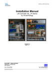
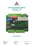
INSTALLATION MANUAL Installation Manual Lift Controller ISL_V2 Series by IS technology VERSION V2 (REV 2.4) ________________________________________________________________________ FACTORY - HEAD OFFICE: PERREVOU 37, THESSALONIKI 54352, GREECE TEL.: +30 231 220 9009 FAX.:+30 2310 943169 email: [email protected] URL: www.istechnology.gr ________________________________________________________________________________________________ Copyright IS technology 2011 INSTALLATION MANUAL INDEX 1. Technical Specification of Lift Controller ISL-V2. 1.1 Technical Features....................................................... Page 2. 1.2 Symbols ....................................................................... Page 3. 1.3 ISL_V2 Controller Terminal Description ....................... Page 4. 1.4 Typical Wiring Diagram for ISL-V2 Controllers............. Page 6. 1.5 Counting System Installation for ISL_V2 controllers .... Page 7. 2. Electronic Modules for ISL_V2 Controllers 2.1 Power Drive Module PDM_V3 (For Valve block drive) ........ Page 8. 2.2 Auxiliary Elevator Board AEB_V5 ................................ Page 8. 2.3 Lift Control Board ISL_V2 (Astra_V2) .......................... Page 9. 2.3.1 Terminal Description ................................................. Page 9. 2.3.2 ASTRA - V2 User Interface ..................................... Page 10. 2.3.3 Fault Log ................................................................. Page 11. 2.3.4 Programming Menu................................................. Page 12. Appendix Certificates & Guaranty .................................................... Page 13. 1 INSTALLATION MANUAL 1. Technical Specification of Lift Controller ISL-V2. 1.1. Technical Features. Control panel features Dimensions Power supply - Power Lines Safety circuit voltage Signals & Indicators electrical ratings Transformers • Electrostatic Painted • Protection Class IP-54 • Wall mounting set included • Machine Room Stop Switch, Cabin at floor indication and power switch included 1.Traction 800 x 700 x 180 mm 2.Hydraulic 3.INVERTER- VVVF 900 x 750 x 250 mm 400 VAC (3Ph , PE) - Motor supply 230 VAC (L, N) – Lightning , Controller supply 230 VAC (Lu, Nu) – UPS Supply 110 V AC 24 V DC Peak Max Current 5Α Average Max Current 3Α • Power: 520 VA (Main Transformer – Typical) Primary: 0-230-240-400-410 V AC Secondary A: 0-55-65-115-135V AC (400VA) Secondary B: 0 – 17Vac (20VA) Secondary C: 0 – 15 - 18 - 20Vac (100VA) • Power: 300 VA (Lightning Transformer for 42Vac Cabin Lights) Primary: Secondary: Main Contactors Battery Counting Method No off Stops Lightning Cam - Brake Coil (Traction) Cam - Valves (Hydraulic) Indicators (DISPLAYS) Direction Arrows 0-230-240 AC 0 - 20 - 42V AC (300VA). Category: AC3 12 Volt –2.3 Αh Magnetic Switches (Pencil switches) or Hall sensors (Optionally >1.6m/sec) Eight (8) • • • • Collective Down Cabin: 42VAC – 300W / 220VAC – 900W Shaft: 220VAC – 900W Two Separate rectify circuits Voltage ratings: 48 or 110VDC ABC (Binary coded) Max Current Ratings: 1A (Per Signal) Max Current Ratings: 2A (Per Signal) 2 INSTALLATION MANUAL 1.2. Symbols. SYMBOL Description U Modules F Fuse Terminal Group Voltage Description Χ1 400Vac 3 phase circuits (Supply, Motor Output) Χ2 230Vac 1 phase (Supply, Lights) Χ3 <230Vac Doors, Cam, Brake control Χ4 48/12Vdc Valves G Encoder J Terminal Χ5 110Vac or 48Vdc Contactor (Auxiliary contactor) Χ6 12Vdc K (KT) Ι Coil M Motors - Fan FL Filters R Resistance S MCB TR Transformer X Terminal Group Safety elements Battery Χ7 24Vdc Control Signals Χ8 24Vdc Calls and Indicators Table 2: Terminal Groups Table 1: Drawing Symbols No Color size voltage 1 Orange 0,75 mm² 110 Vac Used in .... No SYMBOL Safety circuit (Phase) Relay Coils 2 Yellow 0,75 mm² Neutral 110Vac +12Vdc 3 Red 0,75 mm² Name/Value S1 Main Switch • 3x32A (5.5kw) • 3x40A(7.5kw) • 3x63A(11kw) S2 Shock Protection MCB / 30mA 3 Ι1 Latch Relay / 48VAC 4 S3 Safety Circuit / 2Α 5 S4 Controller / 6Α 6 S5 24V / 6Α 1 Safety circuit (Neutral) Relay Coils Battery circuit (Battery +) 2 +48 Vdc Valves + +110 Vdc Brake + / Cam + 0 Vdc Brake- / Cam- / Valves- 4 Light Grey 0,75 mm² 5 Grey 0,75 mm² 0 Vdc 24 Vdc - / 12Vdc - 7 Blue 0,75 mm² 230 Vac Mains Neutral 8 Brown 0,75 mm² 230 Vac Mains Phase 0,38 mm² 24 Vdc S6 Shaft Lights / 10Α Black Control Signals (Calls, Count Display – Inspection) 7 9 4mm²(min) 400 Vac Power Cables 8 S7 Cabin Lights / 10Α (220Vac) - 4A (42Vac) 9 S8 Doors • 10Α (Automatic) • 3x10Α (3 Phase automatic) • 2Α (Folding Cabin doors) 10 S9 • Brake / 6Α (Traction) • Valves / 6Α (Hydraulic) 11 S10 10 Yellow-Green 0,5 mm² Groung 2.5mm²(min) 11 Green 0,75 mm² 42 Vac Cabin lights 42Vac 12 White 0,75 mm² 42 Vac Permanent Cabin lights 20Vac 13 Magenta 0,75 mm² 125 Vac Cam (AC) 125 Vac Brake (AC) 14 Pink 0,75 mm² 48 Vac Valves (AC) Cam / 6A (for 1 cam) KAMA / 10A (for 2 cams) Table 3: Wiring of ISL controllers 12 SU UPS / 6A (FU = 6A FUSE) 13 I2 Shaft Light Latch Relay / 220Vac Table 4: MCB's 3 INSTALLATION MANUAL 1.3. ISL_V2 Controller Terminal Description. Category Terminal Group Machine Room Machine Room Machine Room Machine Room Flat Cable Machine Room X1 X1 X1 X1 X1 Χ1 Machine Room Machine Room Machine Room Flat Cable Shaft - Loom Χ2 Χ2 Χ2 Χ2 Χ2 Shaft & Loom Χ2 Flat Cable Χ2 Flat Cable Χ2 Flat Cable Χ3 Flat Cable Χ3 Flat Cable Χ3 Flat Cable Χ3 Flat Cable Χ3 Machine Room Flat Cable Χ3 Χ3 Machine Room Machine Room Machine Room Machine Room Machine Room Machine Room Machine Room Machine Room Χ4 Χ4 Χ4 Χ4 Χ4 Χ4 Χ4 Χ4 Machine Room Shaft - Loom Shaft - Loom Shaft - Loom Machine Room Flat Cable Shaft - Loom Shaft - Loom Flat Cable Χ5 Χ5 Χ5 Χ5 Χ5 Χ5 Χ5 Χ5 Χ5 Flat Cable Flat Cable Flat Cable Flat Cable Χ6 Χ6 Χ6 Χ6 Flat Cable Machine Room / Flat Cable Machine Room & Flat Cable Flat Cable Flat Cable Χ7 Χ7 Χ7 Χ7 Χ7 Name Description 3 phase connections (High Voltage 400Vac) PE Ground R,S,T Input of 3 phase supply – Mains L1, L2, L3. U1,V1,W1 Output Motor (In traction 2 speed machine - Fast speed winding) U2,V2,W2 Output Motor (In traction 2 speed machine - Slow speed winding) Ud,Vd,Wd Output Motor of 3phase Automatic Door Β1, Β2 Braking resistance VVVF One Phase Supply (Voltage 230Vac) L, N Single Phase Mains Input 220Vac Lu, Nu Single Phase Input from UPS 220Vac (in VVVF only) SU:L, SU:N Single Phase Output for UPS Charge 220Vac PE – Ld – Nd Door Supply output 220Vac ΦΦ:L – ΦΦ:N Shaft Lights Output 220VAC (900W max.) (ΦΦ:L = Phase / ΦΦ:Ν = Neutral) ΦΦ.Β – ΦΦ:N Shaft Lights Control Button. We can connect in parallel as many push *(AEB-V1 to AEB-V4) button as we need for controlling the shaft lightning **Cabin Lights output 42 / 220VAC (300 / 900 W max). ΦΘ:L – ΓΘ:Ν ** (ΦΘ:L = Phase / ΓΘ:Ν = Neutral) Cabin Socket 230Vac ΡΘ:L – ΓΘ:Ν **** (ΡΘ:L = Phase / ΓΘ:Ν = Neutral) Door - Cam - Brake Control (Voltage <230Vac) 41β 1. Open Door B Command Output (Relay Output). 2. Opening Final Switch in 3 phase Automatic Door Β (NC). 42β 1. Close Door B Command Output (Relay Output). 2. Closing Final Switch in 3 phase Automatic Door Β (NC). 4C 1. Door commands Common (Relay Output). 2. Common for Door Final Switches in 3 phase Automatic Doors 42α 1. Close Door A Command Output (Relay Output). 2. Closing Final Switch in 3 phase Automatic Door A (NC). 41α 1. Open Door A Command Output (Relay Output). 2. Opening Final Switch in 3 phase Automatic Door A (NC). ΦΡ+ , ΦΡBrake Output (4Α) ΜΓ+ , ΜΓCam Output (6Α) Valves Control (Voltage +48/12Vdc) Αμα Slow Up Valve Output (+48Vdc) ΒΜα Fast Up Valve Output (+48Vdc) CMκ Fast Down Valve Output (+48Vdc) Dμκ Slow Down Valve Output (+48Vdc) ΓΒ Common Valves Signal (-48Vdc / -12Vdc) VMP Bypass Valve for IGV (-48Vdc) ΒΑ+ Rescue Valve Positive Output (+12Vdc / 4Α) ΒΑRescue Valve Negative Output (-12Vdc) Safety Elements (Voltage 110Vac or 48Vdc) Θ1 – Θ2 Motor / Oil Thermistor - PTC ΤΔ1 , ΤΔ2 Final Switches (NC). ΤΔ2 , ΡΕΓ Over speed Governor (NC). ΡΕΓ, ΣΦ Shaft Stop Switches (NC). ΣΦ, ΠΧ Low Pressure (Rapture Valve) contact (NC). ΠΧ , ΣΘ Cabin Stop Sequence (Safety Gear - Inspection Stop) (NC). ΣΘ , ΕΠ Shaft Doors Contacts (NO). ΕΠ , ΚΛ Semi Automatic interlock Contact (NC). ΚΛ , ΘΘ Cabin Door Contact (NC). Battery Circuit (Voltage 12Vdc) ΦΑ Emergency Light, +12Vdc. ΕΚΔ Input From Siren Push Button - Output to Siren +12 Battery positive voltage output +12Vdc Battery negative output 0Vdc Control Signal inputs (Voltage 24Vdc) +24 , FUL Full Load - (NO / +24V). +24 , ΥΠ Overload Contact - (* as ordered / +24Vdc). +24 , SL *(AEB-V5) +24 , ΕΧP +24 , FIRE Shaft Lights Trigger - (NO / +24Vdc). Express (Cancels all landing calls) - (NO / +24V). Fire Alarm - (NO / +24V). 4 INSTALLATION MANUAL Flat Cable Flat Cable Flat Cable Flat Cable Flat Cable Flat Cable Flat Cable Flat Cable Flat Cable Flat Cable Χ7 Χ7 Χ7 Χ7 Χ7 Χ7 Χ7 Χ7 Χ7 Χ7 Flat Cable Χ7 Shaft - Loom Flat Cable Shaft - Loom & Flat Cable - Χ8 Χ8 Χ8 Χ8 ΤΕ Shaft - Loom & Flat Cable Shaft - Loom & Flat Cable Shaft - Loom & Flat Cable Shaft - Loom & Flat Cable Flat Cable Flat Cable Flat Cable Χ8 A,B,C Indicator Signal Voltage selection (Connect to +24 or - depending the Display) Indication Signals - Binary (Output Voltage = ΤΕ) Χ8 L1, L2 .... L8 Indication Signals - Decade (Output Voltage = ΤΕ) Χ8 UP▲ Up direction Arrow (Output Voltage = ΤΕ) Χ8 Dn▼ Down direction Arrow (Output Voltage = ΤΕ) Χ8 Χ8 Χ8 Gong , +24 ΛΥΠ , ΓΚΘ / ΓΕΘ / K1 - Κ8 Shaft - Loom Χ8 ΓΚΦ / ΓΕΦ / D1 - D8 Gong (+24 Vdc) Overload Indication output (Output voltage +24) Cabin Calls 1 - 8. Common for Landing Calls = ΓΚΘ Common for Call Registered Indication = ΓΕΘ Landing Down Calls 1 - 8. Common for Landing Calls = ΓΚΦ Common for Call Registered Indication = ΓΕΦ Speaker Output for Voice announce Module or MP3 Module Flat Cable Χ8 Table 5: Terminal Description ISL_V2 +24, REV +24, RUP +24, RDN ZA1 - ΖΑ2 ZB1 - ΖΒ2 +24, ΠΑ +24, ΠΚ +24, ΣΑΑ +24, ΣΑΚ +24 , DO Inspection - (NC / +24Vdc) (Closed = Inspection / Opened = Normal) Inspection Down - (NO / +24V). Inspection Up - (NO / +24V). Relevelling Zone Α (NO / +24V). Relevelling Zone B (NO / +24V). Down Preliminary - (NC / +24V). Up Preliminary - (NC / +24V). Up Count / Stop Switch (NO / +24V). Down Count / Stop Switch (NO / +24V). Door Open Push Button || Photocell NO Contact || Obstruction NO Contact +24 , DC Door Close Push Button Calls And Indicators (Voltage 24Vdc) +24Φ Voltage Output +24Vdc for Shaft Wiring Voltage Output +24Vdc for Cabin Wiring +24*** Voltage Output 0Vdc (GND of +24V) SP1 , SP2 5 INSTALLATION MANUAL 1.4. Typical Wiring Diagram for ISL-V2 Controllers. 6 INSTALLATION MANUAL 1.5. Counting System Installation for ISL_V2 controllers. 7 INSTALLATION MANUAL 2. Electronic Modules for ISL_V2 Controllers. 2.1 Power Drive Module PDM_V3 (For Valve block drive). In ISL Lift Controllers and specific in Hydraulic lift Applications the valve block is driven by a specially designed module named PDM_V3. PDM module supports all known Valve blocks and ensures their fine operation with maximum safety. 2.2 Auxiliary Elevator Board AEB_V5. AEB Module is caring all necessary electrical circuit for the Lift application. This Board is designed to cooperate along with the main controller and offers double safety while minimizes the need of using external elements. 8 INSTALLATION MANUAL 2.3 Lift Control Board ISL_V2 (Astra_V2). 2.3.1 Terminal Description The Astra_V2 elevator control board is the "brain" of the controller. Controls all signals for lift applications up to 8 stops collective down. This board is designed according the EN81.1-2 norm and ensures that vertical transport is conducted with maximum safety. Terminal Low_SP Hi_SP UP_DIR DN_DIR SPRE_1 Name ΚΤ2 ΚΤ3 UP DWN PROG. OUT 1(ΚΤ1) Traction 2Sp Slow Fast Up Down Programmable Hydraulic Relevelling Fast Up Down Delta VVVF Multi Speed 1 Multi Speed 2 FWD REV Multi Speed 3 9 Speed ΚΤ1 ΚΤ2 ΚΤ3 Nominal (50Hz) Leveling (5Hz) Inspection (20Hz) Intermediate. (35Hz) 0 0 0 1 0 1 1 0 1 1 0 1 Multi Speed 1 3 2 5 INSTALLATION MANUAL 2.3.2 ASTRA - V2 User Interface. To operate or setup the ASTRA-V2 Elevator PCB module we can use the 4 ON Board Dip Switches and the 3 push button. The Astra - V2 Module has a 3 digit LCD screen where the user can see all necessary information for programming or troubleshoot the controller. Operation Messages in Astra - V2 LCD Screen: Page 1 FL# In Normal Operation Floor Number is Displayed. When the Floor Number is unknown, then in floor No we have '-'. In# E## ESt Page 2 Err Inspection Operation Current Fault '##' Safety Stop Opened By Pressing SELECT we can insert to Error Log. 'noE' Means No Errors registered. With Previous and Next Button, we can navigate in Error Log Menu. Page 3 Fer By Pressing SELECT we can insert to Fatal Errors Log. 'noE' Means No Fatal Errors registered. With Previous and Next Button, we can navigate in Fatal Error Log Menu. (Fatal Errors are All Level ΙΙ Fault, See Error Menu) Page 4 ErA By Pressing SELECT we can Erase all registered Faults. 'noF' means that faults are erased. Page 5 Htr By Pressing SELECT we can reset the controller and conduct a homing trip. Programming Menu. In Normal Operation must be OFF. After Power ON if this switch is in ON position then we can insert the programming Menu. By putting this switch back to Off, all the parameters are saved and we go back to normal operation. PTC Protection. ON: PTC Protection Disabled OFF: PTC Protection Enabled Elevator Type. OFF: Traction Lift ON: Hydraulic Lift Door Type: OFF: Automatic Doors ON: Swinging Doors • • Simulate Calls With Astra - V2: When we are in Page 1 and the screen shows FL# by pressing Select the indication changes to Fr# and the # is flashing. With Prev and Next button we can alter the Floor No we want to simulate call. When we set the desired target Floor No by pressing the Select Button a new call is registered from the desired floor and the corresponding LED in Astra Lights. To deactivate the simulate calls function press select for 3 sec. Inspection Commands: When we are in Page 1 and In# is written on screen, by pressing Prev and Next buttons we can give up or down command for inspection operation 10 INSTALLATION MANUAL 2.3.3 Fault Log. Error Code Fault Description *Level Action taken 20 Safety circuit and/or door opened during travel Safety circuit opened during travel Ι Waits for safety circuit to close Ι 21 Door lock circuit opened during travel Ι 22 Safety circuit failed to close after door closing Failure in locking door after 3 attempts Failure in closing door Ι Waits for safety circuit to close, cancels calls if fault persists more than 5sec3 Waits for lock circuit to close, cancels calls if fault persists more than 5sec3 Cancels calls and opens door3 Ι Cancels calls3 ΙΙ 20 22 22 ΙΙΙ Cancels calls, opens door3 Blocks elevator4 ΙΙΙ Blocks elevator4 26 UP Preliminary Switch fault (Moving Down And the up preliminary sw. is activated) Down Preliminary Switch fault (Moving Up And the down preliminary sw. is activated) Counting Error ΙΙ 26 Counting Error ΙΙ 28 Preliminary Switches Fault (both open) Emergency stop ΙΙΙ Performs a homing trip Performs a homing trip Blocks elevator7 Motor has been powered for 25 sec, car did not move Preset number of operating days expired All orders on contactors were removed, one contactor or more is still engaged Motor temperature has exceeded its maximum allowable operating temperature Locks/Cabin doors opened during travel ΙΙΙ Waits for a car call to resume Blocks elevator4 ΙΙΙ Blocks elevator11 Ι Waits all contactors to be released Ι Elevator is stopped at the nearest floor. Waits for the motor to cool down Ι Waits for lock circuit to close, cancel calls if fault persists more than 5sec3 Blocks elevator 24 25 27 29 35 33 34 23 32 Ι ΙΙΙ Final switches opened For swinging or ½ automatic door. 2 For automatic door. 3 Waits for a call to resume operation. 4 When the cause of the fault is diagnosed and fixed, empty the faults log or request a homing trip so that the elevator resumes operation. 5 When DZ magnetic switch is installed. Refer to section 5. 6 When DZ magnetic switch is installed. Refer to section 5. 7 When the cause of the fault is diagnosed and fixed, the elevator will automatically resume operation. 8 Relevant in group mode only. 9 Refer to section 5. 10 In case of automatic door, waits for obstacle to clear. 11 To recover from this fault, access menu and clear the count of elapsed days. Refer to Chapter Programming Menu. 1 11 INSTALLATION MANUAL 2.3.4 Programming Menu. To Enter the programming Menu follow the steps: 1. Turn Off the controller 2. Put the Dip Switch No4 in ON position 3. Power on the controller 4. Navigate the Menu with Next and Prev Buttons and Press select for saving new values. To Leave programming Menu Just put the Dip Switch No4 back to Off position. Παράμετρος Par Lgt FLt LdF Ldt Cjd Ado SPr Πεδίο Τιμών Opn - CLd Selects the parking mode for automatic door: OPn = Parking door opened CLd = Parking door closed Sets the car light time Sets the floor stopping time Sets the landing floor Sets the landing time Set the car jammed delay Sets the opening time of the Automatic Door In case Hydraulic is not selected, sets the STAR output function: gong, intermediate speed1 (used in VVVF operation) or base block (used in VVVF operation) dΞo When enabled, SDFS DN input is re-assigned as DZ for automatic door only. DZ should be active on every floor stop to allow door opening When enabled, CLSE input is re-assigned as emergency stop for swinging door only Edi Aro CjF roL Str Arrows Type (With Next Direction Indication = Std / Only Present Direction Indication = run) Sets The Level for Car Jammed Fault Sets the logic for Reopen-Overload Input Sets the start time in hydraulic mode. If hydraulic is not selected, it selects VVVF and sets the start delay: Zero: AC2-speed is selected (StP has to be set to zero as well) Positive value: VVVF selected with direction engaging before speed reference Negative value: VVVF selected with speed reference engaging before direction Selects VVVF and sets the Stop delay: Zero: AC2-speed is selected (Str has to be set to zero as well) Positive value: VVVF selected with speed reference disengaging before direction Negative value: VVVF selected with direction disengaging before speed reference Sets the re-leveling option in hydraulic mode StP rLL EoS PoH Ind Enables the EOS during the inspection Enables Power-on homing grA = Gray code floor information output gr1 = Gray code floor information output starting from 1 bin = Binary code floor information output EnH = Enhanced scrolling display information output Sets the number of basement (affects the direction of the hall calls) Enables permanent close for automatic door Press push button to access CODE MENU2 bAS PCL Cod • Περιγραφή 0 - 25.0 sec 0 - 25.0 sec non, 0 - 7 1 - 99 min Dis, 1 - 255sec Dis, 1 - 255sec gng = Gong Int = Μεσαία Ταχ. bbL = Base Block DiS - EnA DiS Std - run L3 / L2 nc/no -9,9 - 9,9sec -9,9 - 9,9sec ALL = Always SEL = Closed Doors DiS - EnA DiS - EnA bin grA gr1 Enh 0-7 DiS - EnA 'Select' Code Menu. A blank screen appears with a decimal point on the first digit. Use the INC and DEC push buttons to set the first digit of the code. Use OK to enter it. The digit is instantaneously replaced by “c”. A decimal point on the second digit prompts you to enter the second digit of the code by repeating the above procedure. Repeat this process until all six digits are entered. Παράμετρος StA ELA DAy out Περιγραφή Selects the status of the code lock feature Press INC or DEC push buttons to change selection DiS = Disabled / EnA = Enabled Displays the count of the number of days elapsed Pressing INC or DEC push buttons resets counter to zero Displays the preset number of operating days Modify by pressing INC and DEC push buttons. Enter new value with OK Press SELECT push button to exit code menu and go back to auxiliary functions menu 12 Πεδίο Τιμών DiS - EnA 0 - 999 - INSTALLATION MANUAL IS technology PERREVOU 37 54 352, THESSALONIKI TEL: +30 2310 943169 FAX: +30 2310 943169 E-mail: [email protected] 24 Months Product Guaranty Name: Address: Telephone: Fax: ISL Controller Type : Shipping Date Code Model : : : The Product guaranty is valid within 24 months from shipping date and only if: The installation was done according our drawings No alterations was made in the product without the knowledge of IS technology Production Department The product was working under normal conditions (Humidity, Temperature) This Controller has passed quality control by Lift Auto tester Machine (IS Property) and was produced according the: 95/16/EU, 89/336/EU, 73/23/EU, ΕΝ81-1 and ΕΝ81-2. For any injury or damage caused from wrong wiring of the controller, IS technology has no responsibility what so ever. Thessaloniki, Greece …../…../20... General Manager: Mr. Thomas Kelantonis 13 INSTALLATION MANUAL 14 INSTALLATION MANUAL Declaration of Conformity CE EMC Compliance Standards and Directive: 89/336/EU & 95/54/EC The Company : IS technology PERREVOU 37 54 352, THESSALONIKI GREECE Declare that the products listed below are following the provisions of the 89/336/EU & 95/54/EC directive. The tests was made by EMC Hellas (Protocol No.: E10/033): Product: 1. Elevator Controller 1.1 For Hydraulic Elevators 1.2 For Traction Elevators Type: ISL_ HYD_ TR_ Thessaloniki 26-04-2010 The Company, IS technology 15