1
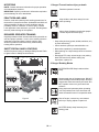
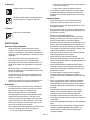
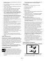
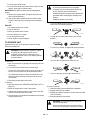
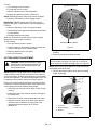
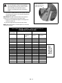
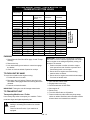
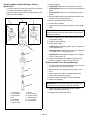
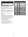
WASP
Owner/Operator Manual
Manuel Du Propriétaire/Utilisateur
Models
988410 - EGWKA1332S
988411 - EGWKA1336S
988412 - EGWKA1548S
ENGLISH
FRANÇAIS
03823902 1/09
Printed in USA
TABLE OF CONTENTS
Safety . . . . . . . . . . . . . . . . . . . . . . . . . . . . . . . . . . . . . . 3
Service and Adjustments . . . . . . . . . . . . . . . . . . . . . 18
Assembly . . . . . . . . . . . . . . . . . . . . . . . . . . . . . . . . . . . 9
Storage . . . . . . . . . . . . . . . . . . . . . . . . . . . . . . . . . . . . 26
Controls and Features. . . . . . . . . . . . . . . . . . . . . . . . 10
Troubleshooting . . . . . . . . . . . . . . . . . . . . . . . . . . . . 27
Operation . . . . . . . . . . . . . . . . . . . . . . . . . . . . . . . . . . 11
Specifications . . . . . . . . . . . . . . . . . . . . . . . . . . . . . . 28
Maintenance Schedule . . . . . . . . . . . . . . . . . . . . . . . 17
Warranty . . . . . . . . . . . . . . . . . . . . . . . . . . . . . . . . . . 30
INTRODUCTION
NON-ENGLISH MANUALS
MODEL AND SERIAL NUMBERS
Manuals in languages other than English may
be obtained from your Dealer. Visit your dealer
or www.ariens.com for a list of languages
available for your equipment.
When ordering replacement parts or making service
inquiries, know the Model and Serial numbers of your unit
and engine.
Manuals printed in languages other than English
are also available as a free download on our
website:
Numbers are located on the product registration form in the
unit literature package. They are printed on a serial number
label, located on the frame of your unit.
Unit Serial
Number Label
www.everride.com
Engine Serial
Number Label
Manuales en idiomas diferentes del ingles
Puede obtener manuales en idiomas diferentes
del inglés en su distribuidor. Visite a su
distribuidor o vaya a www.ariens.com para
obtener una lista de idiomas disponibles para su
equipo.
También puede imprimir manuales en idiomas
diferentes del inglés descargándolos
gratuitamente de nuestra página Web:
www.everride.com
Manuels non anglais
Des manuels dans différentes langues sont
disponibles chez votre revendeur. Rendez-vous
chez votre revendeur ou allez sur le site
www.ariens.com pour consulter la liste des
langues disponibles pour votre équipement.
Figure 1
•
Record Unit Model and Serial numbers here.
•
Record Engine Model and Serial numbers here.
Les manuels imprimés dans des langues
différentes de l’anglais sont également
disponibles en téléchargement gratuit sur notre site Web :
www.everride.com
THE MANUAL
Before operation of unit, carefully and completely read your
manuals. The contents will provide you with an
understanding of safety instructions and controls during
normal operation and maintenance.
All reference to left, right, front, or rear are given from
operator standing in operation position and facing the
direction of forward travel.
GB - 2
© Copyright 2009 Ariens Company
PRODUCT REGISTRATION
DISCLAIMER
The dealer must register the product at the time of purchase.
Registering the product will help the company process
warranty claims or contact you with the latest service
information. All claims meeting requirements during the
limited warranty period will be honored, whether or not the
product registration card is returned. Keep a proof of
purchase if you do not register your unit.
EverRide reserves the right to discontinue, make changes
to, and add improvements upon its products at any time
without public notice or obligation.The descriptions and
specifications contained in this manual were in effect at
printing. Equipment described within this manual may be
optional. Some illustrations may not be applicable to your
unit.
UNAUTHORIZED REPLACEMENT PARTS
DEALER DELIVERY
Use only EverRide replacement parts. The replacement of
any part on this vehicle with anything other than an EverRide
authorized replacement part may adversely affect the
performance, durability, or safety of this unit and may void
the warranty. EverRide disclaims liability for any claims or
damages, whether warranty, property damage, personal
injury or death arising out of the use of unauthorized
replacement parts. To locate your nearest EverRide Dealer,
go to www.EverRide.com on the internet.
Dealer should:
1. Check all controls for proper function.
2. Check the safety interlock system to make sure that it
is functioning properly. (See Check Safety Interlock
System on page 11.)
3. Fill out Original Purchaser Registration Card and
return the card to EverRide.
4. Explain Limited Warranty Policy.
5. Explain recommended lubrication and maintenance.
Advise customer on adjustments.
6. Instruct customer on controls and operation of unit.
Discuss and emphasize the Safety Precautions. Give
customer Owner/Operator, Parts, and Engine
Manuals. Advise customer to thoroughly read and
understand them.
SAFETY
WARNING: This cutting machine is capable
of amputating hands and feet and throwing
objects. Failure to observe the safety
instructions in the manuals and on decals
could result in serious injury or death.
Slopes are a major factor related to
loss-of-control and tip-over accidents.
Operation on all slopes requires extra
caution.
Tragic accidents can occur if the operator is
not alert to the presence of children. Never
assume that children will remain where you
last saw them.
SAFETY ALERTS
Look for these symbols to point out important
safety precautions. They mean:
Attention!
Personal Safety Is Involved!
Become Alert!
Obey The Message!
The safety alert symbols above and signal words below are
used on decals and in this manual.
Read and understand all safety messages.
DANGER: IMMINENTLY HAZARDOUS
SITUATION! If not avoided, WILL RESULT
in death or serious injury.
Gasoline is extremely flammable and the
vapors are explosive, handle with care.
Disengage attachment, stop unit and engine,
remove key, engage parking brake, and allow
moving parts to stop before leaving
operator’s position.
WARNING: POTENTIALLY HAZARDOUS
SITUATION! If not avoided, COULD
RESULT in death or serious injury.
CAUTION: POTENTIALLY HAZARDOUS
SITUATION! If not avoided, MAY RESULT in
minor or moderate injury. It may also be
used to alert against unsafe practices.
GB - 3
NOTATIONS
1. Danger! To avoid serious injury or death
NOTE: General reference information for proper operation
and maintenance practices.
Read the operator’s manual.
IMPORTANT: Specific procedures or information required to
prevent damage to unit or attachment.
OL1801
PRACTICES AND LAWS
Keep children and others away from unit
while operating.
Practice usual and customary safe working precautions, for
the benefit of yourself and others. Understand and follow all
safety messages. Be alert to unsafe conditions and the
possibility of minor, moderate, or serious injury or death.
Learn applicable rules and laws in your area, including those
that may restrict the age of the operator.
OL4370
Never direct discharge toward other people.
Thrown objects can cause injury.
REQUIRED OPERATOR TRAINING
Original purchaser of this unit was instructed by the seller on
safe and proper operation. If unit is to be used by someone
other than original purchaser; loaned, rented or sold,
ALWAYS provide this manual and any needed safety
training before operation.
•
Keep safety devices (guards, shields, switches, etc.)
in place and working.
•
Check interlock system per manual before use.
SAFETY DECALS AND LOCATIONS
•
Never allow operation by untrained persons.
ALWAYS replace missing or damaged Safety Decals. Refer
to figure below for Safety Decal locations.
•
When parking on a slope always chock or block the
wheels.
•
Disengage PTO, stop unit and engine, set parking
brake and remove key before making any
inspections, repairs, etc.
OL0910
1
2. Danger! Rotating Blades
3
ROTATING BLADE! Keep hands and feet
away.
4
OL3030
2
OL0910
Always stand clear of discharge area. DO NOT
direct discharge toward other people. Remove
objects that could be thrown by the blade. DO
NOT operate mower over gravel and hard
surfaces.
Keep people and pets away when operating
unit. Keep children out of the work area and
under the watchful care of a responsible adult.
OL4370
Figure 2
Shut off engine, remove key, read manual
before you unplug, adjust or repair unit.
OG1491
OL4010
NO STEP! Always keep feet away from
rotating parts.
OL4420
GB - 4
b. Never remove gas cap or add fuel when engine is
running. Do not smoke.
3. Warning!
(
c. Never refuel or drain the machine indoors.
Always stand clear of discharge.
•
OL0910
DO NOT operate mower unless guards are in
operating position or bagger is attached.
Check that the operator’s presence controls, safety
switches and shields are attached and functioning
properly. Do not operate unless they are functioning
properly.
Operating Safely
•
Never run an engine in an enclosed area where
dangerous carbon monoxide fumes can collect.
•
Only operate in good light, keeping away from holes
and hidden hazards.
•
Be sure all drives are in neutral and parking brake is
engaged before starting engine. Only start engine from
the operator’s position.
•
Be sure of your footing while using
pedestrian-controlled equipment, especially when
backing up. Walk, don’t run. Never operate on wet
grass. Reduced footing could cause slipping.
•
Read the operator’s manual and other training
material. If the operator or mechanic cannot read
English, it is the owner’s responsibility to explain this
material to them. This publication is available in other
languages.
Slow down and use extra care on hillsides. Be sure to
travel in the recommended direction on hillsides. For
this machine, drive across hillsides, not up and down.
Turf conditions can affect the machine’s stability. Use
caution while operating near drop-offs.
•
Slow down and use caution when making turns and
when changing directions on slopes.
•
Never raise deck with the blades running.
•
Become familiar with the safe operation of the
equipment, operator controls, and safety signs.
•
•
All operators and mechanics should be trained. The
owner of the machine is responsible for training the
users.
Never operate with guards not securely in place. Be
sure all interlocks are attached, adjusted properly, and
functioning properly.
•
Never operate with the discharge deflector raised,
removed or altered, unless using a grasscatcher. Do
not operate mower without discharge chute or entire
grasscatcher in place.
•
Do not change the engine governor setting or
overspeed the engine. Operating the engine at
excessive speed can increase the hazard of personal
injury.
•
Stop on level ground, lower implements, disengage
drives, engage parking brake, and shut off engine
before leaving the operator’s position for any reason
including emptying the grasscatchers or unclogging
the chute.
•
Stop equipment and inspect blades after striking
objects or if an abnormal vibration occurs. Make
necessary repairs before resuming operations.
•
Keep hands and feet away from the cutting units.
•
Look behind and down before backing up to be sure of
a clear path.
•
Never carry passengers and keep pets and bystanders
away.
•
Slow down and use caution when making turns and
crossing roads and sidewalks. Stop blades if not
mowing. Watch for traffic when operating near or
crossing roadways.
OL3320
4. Danger!
Stay clear of rotating parts.
OL5100
SAFETY RULES
Operator Training Required
•
•
Never let children or untrained people operate or
service the equipment. Local regulations may restrict
the age of the operator.
•
The owner/user can prevent and is responsible for
accidents or injuries occurring to themselves, other
people, or property.
•
Operate the machine in an open, unobstructed area
under the direction of an experienced operator.
Preparation
•
•
Evaluate the terrain to determine what accessories
and attachments are needed to properly and safely
perform the job. Only use accessories and
attachments approved by the manufacturer.
Wear appropriate clothing including hard hat, safety
glasses and hearing protection. Long hair, loose
clothing or jewelry may get tangled in moving parts.
•
Inspect the area where the equipment is to be used
and remove all objects such as rocks, toys and wire
which can be thrown by the machine.
•
Use extra care when handling gasoline and other fuels.
They are flammable and vapors are explosive.
a. Use only an approved container.
GB - 5
•
Be aware of the mower discharge direction and do not
point it at anyone.
•
Do not operate the machine while under the influence
of alcohol or drugs.
•
Use care when loading or unloading the machine into
or off of a trailer or truck.
•
Use care when approaching blind corners, shrubs,
trees, or other objects that may obscure vision.
•
Inspect machine before you operate. Be sure
hardware is tight. Repair or replace damaged, badly
worn, or missing parts. Be sure guards and shields are
in good condition and fastened in place. Make any
necessary adjustments before you operate.
•
•
Study mowing area. Set up a safe mowing pattern. Do
not mow where traction or stability is doubtful.
Parking Safely
1. Stop machine on a level surface, not on a slope.
2. Disengage mower blades.
3. Lock the park brake.
4. Stop the engine.
Before using, always visually inspect to see that the
blades, blade bolts and the mower assembly are not
worn and damaged. Replace worn and damaged
blades and bolts in sets to preserve balance.
5. Remove the key.
6. Wait for engine and all moving parts to stop before you
leave the operator’s station.
7. Close fuel shut-off valve, if your machine is equipped.
8. Remove the spark plug wire (for gasoline engines)
before servicing the machine.
Operating Safely on Slopes
•
Do not wear radio or music headphones. Safe service
and operation require your full attention.
Slopes are a major factor related to slip and fall
accidents which can result in severe injury. Operation
on all slopes requires extra caution. If you feel uneasy
on a slope, do not mow it.
•
•
When machine is left unattended, stored, or parked,
lower the mower deck unless a positive mechanical
lock is used.
Mow across the face of slope, never up and down. Use
extreme caution when changing direction on slopes.
•
Keep all movement on slopes slow and gradual. Do
not make sudden changes in speed or direction.
•
Be sure all drives are in neutral and parking brake is
locked before starting engine. Stand as far away from
the discharge chute as possible with feet well away
from the underside of the deck to start machine.
•
Watch for holes, ruts, bumps, rocks or other hidden
objects. Uneven terrain could cause a slip and fall
accident. Tall grass can hide obstacles.
•
•
Do not hang or secure any item to the control console.
The operator’s station should always remain
unobstructed.
Do not mow on wet grass or excessively steep slopes.
Poor footing could cause a slip and fall accident.
•
Do not mow near drop-offs, ditches, embankments, as
well as ponds and other bodies of water. The operator
could lose footing or balance. The machine could
suddenly turn over if a wheel is over the edge of a cliff
or ditch, or if an edge caves in.
•
Follow the manufacturer’s recommendations for
counterweights for added stability when operating on
slopes. Remove weights when not required.
•
Use extra care with grasscatchers. These can change
the stability of the machine. Do not use grasscatcher
on steep slopes.
•
Keep safety labels visible when installing accessories
and attachments.
•
•
Do not pull mower backwards while the blades are
rotating. Use the reverse gear to move the machine in
reverse.
Using a Spark Arrestor
The engine in this machine is not equipped with a spark
arrestor muffler. It is a violation of California Public Resource
Code Section 4442 to use or operate this engine on or near
any forest-covered, brush-covered or grass-covered land
unless the exhaust system is equipped with a spark arrestor
meeting any applicable local or state laws. Other states or
federal areas may have similar laws.
A spark arrestor for your machine may be available from
your authorized dealer. An installed spark arrestor must be
maintained in good working order by the operator.
Rotating Blades are Dangerous
HELP PREVENT SERIOUS OR FATAL ACCIDENTS:
Checking Mowing Area
•Clear mowing area of objects that might be
thrown. Keep people and pets out of mowing area.
•Low-hanging branches and similar obstacles can
injure the operator or interfere with mowing operation.
Before mowing, identify potential obstacles such as
low-hanging branches, and trim or remove those
obstacles.
GB - 6
•
Rotating blades can cut off arms and legs, and throw
objects. Failure to observe safety instructions could
result in serious injury or death.
•
Keep hands, feet and clothing away from mower deck
when engine is running.
•
Be alert at all times, drive forward carefully. People,
especially children can move quickly into the mowing
area before you know it.
•
Always wear safety goggles, or safety glasses with
side shields, and a hard hat when operating the
machine.
•
Wear close fitting clothing and safety equipment
appropriate for the job.
•
Before backing up, stop mower blades or attachments
and look down and behind the machine carefully,
especially for children.
•
While mowing, always wear substantial footwear and
long trousers. Do not operate the equipment when
barefoot or wearing open sandals.
•
Do not mow in reverse.
•
•
Shut off blades when you are not mowing.
Wear a suitable protective device such as earplugs.
Loud noise can cause impairment or loss of hearing.
•
Park machine safely before leaving the operator’s
station for any reason including emptying the catchers
or unplugging the chute.
Maintenance and Storage
•Never operate machine in a closed
area where dangerous carbon monoxide
fumes can collect.
Rotating Blades are Dangerous Protect Children and Prevent
Accidents
•Disengage drives, lower implement,
lock parking brake, stop engine and
remove key or disconnect spark plug (for
gas engines). Wait for all movement to stop before
adjusting, cleaning or repairing.
Protect Children:
•Tragic accidents can occur if the
operator is not alert to the presence of children.
Children are often attracted to lawn-mowing machines
and mowing activity. Stay alert to the presence of
children. Never assume that children will remain where
you last saw them.
•
Keep children indoors, out of the mowing area, and in
the watchful eye of a responsible adult, other than the
operator, when a mower is being operated.
•
Be alert and turn mower off if a child enters the work
area. They don’t understand the dangers of rotating
blades or the fact that the operator is unaware of their
presence.
•
Never allow a child or an untrained person to operate
the machine.
•
Use extra care when approaching blind corners,
shrubs, trees, or other objects that may block your
view of a child.
Checking Wheel Hardware
•
A serious accident could occur causing serious injury if
wheel hardware is not tight.
•
Check wheel hardware tightness often during the first
100 hours of operation.
•
Wheel hardware must be tightened to specified torque
using the proper procedure anytime it is loosened.
Wear Appropriate Clothing
GB - 7
•
Clean grass and debris from cutting units, drives,
mufflers, and engine to help prevent fires. Clean up oil
or fuel spillage.
•
Let engine cool before storing and do not store near
flame.
•
Shut off fuel while storing or transporting. Do not store
fuel near flames or drain indoors.
•
Park machine on level ground. Never allow untrained
personnel to service machine. Understand service
procedure before doing work.
•
Use jack stands or lock service latches to support
components when required. Securely support any
machine elements that must be raised for service
work.
•
Before servicing machine or attachment, carefully
release pressure from any components with stored
energy, such as hydraulic components or springs.
•
Release hydraulic pressure by lowering attachment or
cutting units to the ground or to a mechanical stop and
move hydraulic control levers back and forth.
•
Disconnect battery or remove spark plug (for gas
engines) before making any repairs. Disconnect the
negative terminal first and the positive last. Reconnect
positive first and negative last.
•
Use care when checking blades. Wrap the blades or
wear gloves, and use caution when servicing them.
Only replace blades. Never straighten or weld them.
•
Keep hands, feet, clothing, jewelry and long hair away
from moving parts. If possible, do not make
adjustments with the engine running.
•
Charge batteries in an open well ventilated area, away
from spark and flames. Unplug charger before
connecting or disconnecting from battery. Wear
protective clothing and use insulated tools.
•
Keep all parts in good working condition and all
hardware tightened. Replace all worn or damaged
decals.
•
Check grasscatcher components and the discharge
guard frequently and replace with manufacturer’s
recommended parts, when necessary. Grasscatcher
components are subject to wear, damage, and
deterioration which could expose moving parts or allow
objects to be thrown.
•
Keep all nuts and bolts tight, especially blade
attachment bolts, to be sure the equipment is in safe
working condition.
•
Check brake operation frequently. Adjust and service
as required.
•
Tire Safety
Explosive separation of a tire and rim parts can cause
serious injury or death:
On multi-bladed machines, take care as rotating one
blade can cause other blades to rotate.
Avoid High Pressure Fluids
•
Hydraulic hoses and lines can fail due to physical
damage, kinks, age, and exposure. Check hoses and
lines regularly. Replace damaged hoses and lines.
•
Hydraulic fluid connections can loosen due to physical
damage and vibration. Check connections regularly.
Tighten loose connections.
•
Escaping fluid under pressure can penetrate the skin
causing serious injury. Avoid the hazard by relieving
pressure before disconnecting hydraulic or other lines.
Tighten all connections before applying pressure.
•
Do not attempt to mount a tire without the proper
equipment and experience to perform the job.
•
Always maintain the correct tire pressure. Do not
inflate the tires above the recommended pressure.
Never weld or heat a wheel and tire assembly. The
heat can cause an increase in air pressure resulting in
a tire explosion. Welding can structurally weaken or
deform the wheel.
•
When inflating tires, use a clip-on chuck and extension
hose long enough to allow you to stand to one side and
NOT in front of or over the tire assembly.
•
Check tires for low pressure, cuts, bubbles, damaged
rims or missing lug bolts and nuts.
•
Search for leaks with a piece of cardboard. Protect
hands and body from high pressure fluids.
Handling Fuel Safely
•
If an accident occurs, see a doctor immediately. Any
fluid injected into the skin must be surgically removed
within a few hours or gangrene may result. Doctors
unfamiliar with this type of injury should reference a
knowledgeable medical source.
To avoid personal injury or
property damage, use extreme
care in handling fuel. Fuel is
extremely flammable and fuel
vapors are explosive:
•Extinguish all cigarettes, cigars,
pipes, and other sources of ignition.
Prevent Fires
•
Machine fires and structure fires can occur if a
machine is stored before allowing it to cool, or if debris
is not removed from around the engine and muffler, or
if stored near combustible materials.
•
Remove grass and debris from engine compartment
and muffler area, before and after operating machine,
especially after mowing or mulching in dry conditions.
•
Empty the grasscatcher completely before storing.
Always shut off fuel when storing or transporting
machine, if the machine has a fuel shutoff.
•
Do not store machine near an open flame or source of
ignition, such as a water heater or furnace.
•
Check fuel lines, tank, cap, and fittings frequently for
cracks or leaks. Replace if necessary.
GB - 8
•Use only an approved fuel
container. Use only non-metal,
portable fuel containers approved
by the Underwriter’s Laboratory
(U.L.) or the American Society for
Testing & Materials (ASTM). If using a funnel, make
sure it is plastic and has no screen or filter.
•
Never remove the fuel tank cap or add fuel with the
engine running. Allow engine to cool before refueling.
•
Never add fuel to or drain fuel from the machine
indoors. Move machine outdoors and provide
adequate ventilation.
•
Clean up spilled fuel immediately. If fuel is spilled on
clothing, change clothing immediately. If fuel is spilled
near machine, do not attempt to start the engine but
move the machine away from the area of spillage.
Avoid creating any source of ignition until fuel vapors
have dissipated.
•
Never store the machine or fuel container where there
is an open flame, spark, or pilot light such as on a
water heater or other appliance.
•
Prevent fire and explosion caused by static electric
discharge. Static electric discharge can ignite fuel
vapors in an ungrounded fuel container.
•
Never fill containers inside a vehicle or on a truck or
trailer bed with a plastic liner. Always place containers
on the ground away from your vehicle before fueling.
•
Remove fuel-powered equipment from the truck or
trailer and refuel it on the ground. If this is not possible,
then refuel such equipment with a portable container,
rather than from a fuel dispenser nozzle.
•
Keep the nozzle in contact with the rim of the fuel tank
or container opening at all times until the fueling is
complete. Do not use a nozzle lock-open device.
•
Never overfill fuel tank. Replace fuel tank cap and
tighten securely.
•
Replace all fuel container caps securely after use.
•
For gasoline engines, do not use gas with methanol.
Methanol is harmful to your health and to the
environment.
Handling Waste Product and Chemicals
Waste products, such as, used oil, fuel, coolant, brake fluid,
and batteries, can harm the environment and people:
•
Do not use beverage containers for waste fluids someone may drink from them.
•
See your local Recycling Center or authorized dealer
to learn how to recycle or get rid of waste products.
•
A Material Safety Data Sheet (MSDS) provides
specific details on chemical products: physical and
health hazards, safety procedures, and emergency
response techniques. The seller of the chemical
products used with your machine is responsible for
providing the MSDS for that product.
ASSEMBLY
3. Check the adjustments outlined in Service &
Adjustments.
WARNING: AVOID INJURY. Read and
understand the entire Safety section before
proceeding.
4. Check engine oil level. See engine manual.
5. Add clean fuel to the fuel tank. See engine manual for
type and grade.
1. Remove the unit from shipping container.
6. Check for loose hardware.
2. Adjust tire pressure to 55 to 110 kPa (8 to 16 psi).
7. Be sure that safety interlock system operates correctly.
See Check Safety Interlock System on page 11.
CAUTION: Avoid injury! Explosive separation of
tire and rim parts is possible when they are
serviced incorrectly:
8. Be sure that unit tracks straight.
Unit must not pull sharply to the left or right when the
steering levers are released. See TRACKING
ADJUSTMENT on page 18.
•
Do not attempt to mount a tire without the
proper equipment and experience to perform
the job.
•
Do not inflate the tires above the
recommended pressure.
•
Do not weld or heat a wheel and tire
assembly. Heat can cause an increase in air
pressure resulting in an explosion. Welding
can structurally weaken or deform the wheel.
•
Do not stand in front or over the tire
assembly when inflating. Use a clip-on chuck
and extension hose long enough to allow you
to stand to one side.
GB - 9
CONTROLS AND FEATURES
7
2
11
6
4
1. Shift Lever
7
2. Steering Lever Latches
3. Steering Levers
2
4. Throttle Lever
5. Ignition Switch
6. PTO Switch
3
7. Operator Presence Controls
3
8. Fuel Cap
1
5
9. Recoil Starter Handle
10. Traction Belt Guard
11. Choke Control
8
9
10
Figure 3
GB - 10
OPERATION
Steering Levers
WARNING: AVOID INJURY. Read and
understand the entire Safety section before
proceeding.
WARNING: AVOID INJURY. When the engine is
running and the shift lever is engaged, releasing
only one steering latch causes the unit to circle
around one drive wheel.
CONTROLS AND FEATURES
ALWAYS hold both steering levers against the
handlebar when releasing the steering lever
latches.
ALWAYS release levers slowly.
See Figure 3 for controls and features locations.
SAFETY INTERLOCK SYSTEM
DANGER: SAFETY INTERLOCK SYSTEM
FAILURE and improper operation of unit can
result in death or serious injury. ALWAYS know
the safety interlock system is operating
properly. See Check Safety Interlock System on
page 11 for testing instructions.
The steering levers are used to steer, operate in forward and
reverse, and stop the unit. When held against the handlebar,
the brakes are engaged.
Steering Lever Latches
The steering lever latches hold the steering levers in the
neutral position and keep the brakes applied.
Check Safety Interlock System
Ignition Switch
Test the safety interlock system at each operation. If the
system does not function properly, do not operate the unit
until repairs are made.
The engine will only start with the PTO disengaged. The shift
lever must be in neutral for engine to start.
Engine must not start unless PTO is disengaged and the
shift lever is in neutral. To test:
OF1212
Operate the ignition switch with the removable
key. The switch uses two positions: Off (1) and
On (2). To start the engine, turn the key to On
(2) and pull the recoil handle. To stop the
engine, turn the key to Off (1).
Throttle Lever
1. With engine off, engage PTO.
1
2. Turn ignition switch to On. Pull recoil start handle.
Engine must not start.
3. Disengage PTO.
The engine MUST stop whenever the operator removes
both hands from controls while the PTO or transmission is
engaged. To test:
The throttle lever changes the speed of the
engine. Move the throttle lever to Fast (1) to
increase engine speed. Move the lever to Slow
(2) to decrease engine speed.
2
OG1180
1. Start engine and engage PTO.
Choke Control
2. Release operator presence control lever(s). Engine
must stop.
Use the choke control to start a cold engine. Pull
the control out to choke the engine. Push the
control in when the engine gets warm.
3. Disengage PTO.
4. Restart engine.
OG1190
5. Place shift lever in Forward.
6. Release operator presence control lever. Engine must
stop.
Operator Presence Control
The operator presence control lever must be pressed to
operate the PTO or traction drive. When the shift lever or
PTO is engaged, releasing the operator presence control
lever stops the engine.
CAUTION: AVOID INJURY. Operate only when
operator presence control is functioning
correctly. See Check Safety Interlock System on
page 11 for testing instructions.
GB - 11
Fuel is blended to give best seasonal performance. To avoid
engine performance problems such as hard starting or vapor
lock, use in-season fuel. Use fuel during warm weather that
was purchased during that season, and use fuel during cold
weather that was purchased during that season.
Shift Lever
The shift lever sets the direction and speed of the unit.
R = reverse
N = neutral
1 = the slowest forward speed
Fuel can become stale in machines with engines that are
used seasonally or infrequently during a season. Stale fuel
can produce varnish and plug carburetor components which
can affect engine performance.
5 = the fastest forward speed.
Keep fuel storage container tightly covered and in a cool
area out of direct sunlight. Fuel can break down and
degrade if not sealed properly or exposed to sun and heat.
Condensation may collect in the fuel tank because of a
variety of operating or environmental conditions and, over
time, may affect your machine’s operation. Fill fuel tank at
the end of daily use and store fuel in plastic containers to
reduce condensation.
For best year-round performance and fuel-handling, add
stabilizer to fuel immediately after fuel purchase. Such
practice helps prevent engine performance problems and
allows fuel storage in the machine all year without draining.
Figure 4
To add fuel to the fuel tank:
PTO Clutch
1
2
1. Put the unit in an open area.
Pull the PTO (power take off) switch On (1) to
engage the mower blades. Push the PTO
switch Off (2) to disengage the mower
blades.
2. Stop the engine.
3. Allow engine to cool.
4. Clean the fuel cap and the area around the fuel cap to
prevent dirt from entering the fuel tank.
OE0260
5. Remove the cap from the fuel tank.
Recoil Starter Handle
6. Fill the fuel tank. Be careful not to spill.
Pull the recoil starter handle to start the engine.
7. Install the cap on the fuel tank and tighten.
FILL FUEL TANK
8. Clean up any spilled fuel before starting the engine.
TO STOP IN AN EMERGENCY
WARNING: Fuel is highly flammable and its
vapors are explosive. Handle with care. Use an
approved fuel container.
1. Release operator presence control(s).
2. Turn the ignition key Off.
NO smoking, NO sparks, NO flames. ALWAYS
allow engine to cool before servicing.
NEVER fill fuel tank when engine is running or
hot from operation.
NEVER fill or drain fuel tank indoors.
Replace fuel cap securely and clean up spilled
fuel.
3. Allow engine to stop completely.
4. Lock steering levers in neutral.
STARTING AND SHUT OFF
Before Each Use
Check each item in Each Use in the Maintenance Schedule.
NOTE: The engine will not start unless the shift lever is in
neutral, and the Power Take Off (PTO) is Off.
Using Proper Fuel
Use regular grade unleaded fuel with an octane rating of 87
octane or higher. Fuel blends containing up to 10% ethanol
or up to 15% MTBE reformulated fuel are acceptable. Do not
use fuel or additives containing methanol as engine damage
can occur.
Recoil Start
Always use fresh, clean fuel that is purchased in a quantity
that can be used within approximately 30 days, or add fuel
stabilizer.
1. Lock the steering lever latches in neutral.
2. Put the shift lever in neutral.
3. Move PTO switch to Off.
4. Set throttle to the proper starting position. If the engine
is cold, choke the engine.
5. Turn ignition switch to On.
6. Grasp recoil starter handle and pull rope out slowly
until it pulls harder. This is the compression stroke.
GB - 12
7. Let the rope rewind slowly.
WARNING: AVOID INJURY. When the engine
is running and the shift lever is engaged,
releasing only one steering latch causes the
unit to circle around one drive wheel.
8. Pull rope with rapid continuous full arm stroke to start
engine. Allow rope to rewind slowly.
IMPORTANT: DO NOT let starter handle snap against
engine.
ALWAYS hold both steering levers against the
handlebar when releasing the steering lever
latches.
ALWAYS release levers slowly.
9. Repeat until engine starts. (If engine does not start,
refer to Engine Manual.)
10. After engine starts, adjust choke as needed. Allow
engine to warm and run smoothly before operating
unit.
•
Shut Off
To move straight forward; slowly release both steering
levers to the full outward position.
1. Lock steering levers in neutral.
2. Shut off the PTO.
3. Move the throttle lever to Slow.
4. Put the shift lever in neutral.
OG1410
5. Turn the ignition key Off.
•
6. Allow engine to stop completely.
To stop unit in neutral, hold levers in the neutral
position.
TO OPERATE UNIT
Operate the unit only in the operator’s position directly
behind the handlebars.
OG1420
•
To lock unit in neutral, engage both steering latches.
WARNING: AVOID INJURY. When the engine
is running and the speed control lever is
engaged, holding only one steering lever in
neutral causes the unit to circle sharply around
one drive wheel.
OG1430
•
To shift unit:
1. Stop unit movement by pulling both steering levers all
the way up.
To turn to the left, pull the left hand lever up.
2. You can move the shift lever one of two ways:
•
•
Continue to hold up both steering levers and use your
knee to move the shift lever to the desired position.
OG1440
•
Lock both steering levers. Move the shift lever to the
desired position. Hold the steering levers up as you
unlock them.
To turn to the right, pull the right hand lever up.
3. Release both steering levers slowly.
To operate:
1. Start the engine (See STARTING AND SHUT OFF on
page 12).
OG1450
To move in reverse:
2. Move the throttle lever to the Fast position.
1. Hold the steering levers against the handlebar.
3. Engage the operator presence control and move shift
lever to desired direction and speed.
2. Engage steering lever latches.
4. Hold steering levers against the handlebar and release
steering latch levers.
3. Engage the operator presence control and move shift
lever to Reverse.
4. Release steering levers slowly.
WARNING: Uncontrolled reverse travel can
result in serious injury.
Do not put shift lever into the reverse position
unless you are prepared to operate in reverse.
GB - 13
To mow:
Top Mounting Holes
1. Lock steering levers in neutral.
2. Put the shift lever in neutral.
3. Move the throttle lever to the fast position.
4. Engage the operator presence control lever.
NOTE: Operator presence control must remain engaged.
5. Move the PTO switch to On to engage mower.
IMPORTANT: NEVER engage the PTO if the mower is
plugged with grass or other material. This will damage the
PTO belt.
6. Move the shift lever to set a slow ground speed.
7. Hold steering levers against the handlebar and release
the lock latches.
8. Release steering levers slowly.
When you know how to operate the unit, select a speed
appropriate to your mowing conditions.
To stop mowing:
1. Lock the steering levers in neutral.
Bottom Mounting Holes
2. Keep one hand on the operator presence control and
move the shift lever to the neutral position.
Figure 5
5. Using a suitable lifting device, lift the front of the
machine.
3. Move the throttle lever to 1/2 speed.
4. Turn off PTO switch.
6. Remove lynch pin and spacer bushing.
CUTTING HEIGHT ADJUSTMENT
IMPORTANT: Do not allow washer (item 4 in Figure 6)
to sit on caster yoke (item 5 in Figure 6). It must be on
top of height-of-cut spacer bushings (item 3 in Figure 6).
WARNING: ALWAYS block wheels, engage
parking brake and know all jack stands are
strong, secure and will hold weight of unit
during maintenance.
NOTE: Adjust caster wheel spacers to keep mower deck
tilted slightly down at the front.
NOTE: Adjust the cutting height using a combination of the
deck mounting location on the deck carrier frame, spacers
on the front casters, and spacers between the mower blades
and the deck spindles. The desired cutting height may be set
by adjusting only the blade spacers and caster spacers.
7. Adjust caster wheel spacers to set the front cutting
height accordingly.
1
2
3
Refer to the cutting height charts below to determine which
combination of deck mounting location, blade spacers and
caster spacers will set the desired cutting height.
4
1. Shut off the unit. See Shut Off on page 13 and "To stop
mowing."
2. Support the rear of the machine and the back edge of
the mower deck.
5
3. Remove the six deck mounting bolts (three per side).
4. Align the mounting holes in the deck frame with the
unit frame and re-install the mounting bolts in the
appropriate holes and tighten to 47-54 N•m
(35-40 lb.-ft).
1. Lynch Pin
2. Spacer Bushing
3. Spacers
4. Washer
5. Caster Yoke
Figure 6
GB - 14
Store unused 1/4"
blade spacers here
when not in use.
WARNING: Sharp edges can cut. Moving parts
can cut off fingers or a hand. Wrap blade(s),
wear sturdy gloves and use extreme caution
when servicing. On multi-blade mowers,
rotation of one blade will cause all blades to
rotate.
8. Remove the mower blade from the spindle and place
the appropriate number of 1/4" spacers between the
spindle and the blade.
IMPORTANT: DO NOT allow the blade to be less than
3.2mm (1/8 in.) above the lip of the mower deck.
9. Replace mower blade and tighten mounting bolt to
163 N•m (120 lb.-ft.).
Figure 7
10. Remove supports from deck and mower frame.
NOTE: Store the unused 1/4" blade spacers on hex bolts
mounted to the deck:
CUTTING HEIGHT CHART – DECK BOLTED TO
FRAME WITH TOP HOLES
Approximate
Cutting Height
1/4" Blade Spacers
1/2" Castor Spacers
cm (Inches)
Stored
Below
Weldment
Above
Weldment
3.2 (1.25)
0
3
0
6
3.8 (1.5)
1
2
0
6
4.4 (1.75)
2
1
0
6
5.1 (2.0)
3
0
0
6
3.8 (1.5)
0
3
1
5
4.4 (1.75)
1
2
1
5
5.1 (2.0)
2
1
1
5
5.7 (2.25)
3
0
1
5
4.4 (1.75)
0
3
2
4
5.1 (2.0)
1
2
2
4
5.7 (2.25)
2
1
2
4
6.35 (2.5)
3
0
2
4
5.1 (2.0)
0
3
3
3
5.7 (2.25)
1
2
3
3
6.35 (2.5)
2
1
3
3
7.0 (2.75)
3
0
3
3
GB - 15
Recommended
Range for Best
Cut Quality
Between
Spindle and
Blade
CUTTING HEIGHT CHART – DECK BOLTED TO
FRAME WITH BOTTOM HOLES
Approximate
Cutting Height
1/4" Blade Spacers
1/2" Castor Spacers
cm (Inches)
Stored
Below
Weldment
0
1
2
3
7.62 (3.0)
8.3 (3.25)
8.9 (3.5)
9.5 (3.75)
8.3 (3.25)
8.9 (3.5)
9.5 (3.75)
0
1
2
3
0
1
2
10.2 (4.0)
8.9 (3.5)
9.5 (3.75)
10.2 (4.0)
10.8 (4.25)
3
0
1
2
3
Above
Weldment
3
3
3
3
3
3
3
3
3
2
1
0
3
2
1
4
4
4
4
5
5
5
2
2
2
2
1
1
1
0
3
2
1
0
5
6
6
6
6
1
0
0
0
0
PARKING
1. Shut off the unit. See Shut Off on page 13 and "To stop
mowing."
2. Remove the key.
Recommended
Range for Best
Cut Quality
7.0 (2.75)
7.62 (3.0)
8.3 (3.25)
8.9 (3.5)
Between
Spindle and
Blade
3
2
1
0
IMPORTANT: Avoid damage! Transporting a machine
on a trailer or on a truck bed at high speeds can result in
hood or engine cover raising and possibly coming off
machine if not secured.
3. Lock both steering lever latches in neutral to engage
the brakes.
•
Position machine on trailer so hood or engine
cover opens from rear of trailer to prevent wind
from blowing hood or cover open.
•
Secure hood or engine cover with existing
machine locks or latches.
•
Secure hood or engine cover with tie down straps
if no locks or latches exist.
4. Chock or block the wheels if parked on a slope.
TO PUSH UNIT BY HAND
To move the unit without the engine running:
1. Put the shift lever in neutral.
2. Disengage the lock latches. Release steering levers.
The brake is disengaged when the steering levers are
released.
1. Drive machine onto a trailer.
3. Push unit to desired location.
3. Place transmission in NEUTRAL.
2. Engage brake lever locks.
4. Shut engine off.
IMPORTANT: Towing the unit will damage transmission.
5. Remove key.
TO TRANSPORT UNIT
6. Turn fuel shutoff valve to off position.
Transporting Machine on a Trailer
7. Fasten machine to trailer with heavy-duty straps,
chains or cables. Both front and rear straps must be
directed down and outward from machine.
Use a heavy-duty trailer to transport your machine. Trailer
must have signs and lights required by law.
CAUTION: Avoid injury! Use extra care when
loading or unloading the machine into a trailer
or truck.
Close fuel shut-off valve, if your machine is
equipped.
GB - 16
MAINTENANCE SCHEDULE
Period
Service
Check Safety Interlock System
Every 50
Hours
Every 100
Hours
WARNING: Safety interlock system failure and improper operation of
unit can result in death or serious injury. Test this system each time
the unit is operated. If this system does not function as described, do
not operate until repairs are made. See Check Safety Interlock
System on page 11.
Check Air Cleaner
Check the air cleaner element before each use. See engine manual for
detailed instructions.
Check Engine Oil
Check the engine oil level before each use. Never operate the engine when
the oil level is low. See engine manual for detailed instructions.
Check Engine Cooling
Check the engine air cooling system before each use. See engine manual for
detailed instructions.
Check Fasteners
Check all nuts, bolts, and other fasteners before each use. Replace missing
or damaged fasteners.
Check Tire Pressure
Check tires for proper inflation, excessive wear or damage before each use.
The correct air pressure is 55 to 110 kPa (8 to 16 psi).
Follow Engine Manual
Maintenance Schedule
Perform scheduled engine maintenance. See engine manual for detailed
instructions.
Check All Belts
Check all belts for wear or damage. If belts slip, check for damaged belt
tensioner.
Mower Blades
Check mower blades for wear. Sharpen or replace as needed. See MOWER
BLADES on page 22.
Clean Air Cleaner Foam
Element
See engine manual for detailed instructions.
General Lubrication
Oil all pivot points and pin connections. Grease lube fittings. See GENERAL
LUBRICATION on page 18.
Change Engine Oil*
Open the petcock to drain oil through oil drain hose on the right side of
engine. See engine manual for additional instructions.
Check Fuel Filter
See engine manual for detailed instructions.
Check Spark Plug
See engine manual for detailed instructions.
Check Muffler
Check muffler for damage or wear. Replace if necessary.
Clean Air Cleaner Paper
Element
See engine manual for detailed instructions.
Each Use
Every 25
Hours
Task
* Change oil after first 8 hours of operation and every 100 hours thereafter.
GB - 17
SERVICE AND ADJUSTMENTS
If unit turns to the left:
1. Reduce the air pressure in the right tire.
WARNING: AVOID INJURY. Read and
understand the entire Safety section before
proceeding.
2. Increase the air pressure in the left tire.
3. Check for brake binding on left wheel and adjust as
needed.
GENERAL LUBRICATION
Apply a small amount of oil to the pivot points as required for
smooth operation (Figure 8).
Apply high quality lithium based grease to all lube fittings
every 50 hours of operation.
ADJUST STEERING LEVERS
For each lever:
1. Turn off the engine, remove the key and allow unit to
cool.
2. Release steering or control levers (Figure 9).
NOTE: 32-Inch Deck Shown.
3. Shift transmission into neutral. Operate steering or
control lever several times. Do not move unit.
2
3
4. Remove the hair pin and disconnect the trunnion from
the wheel clutch weldment.
4
5. Adjust the trunnion on the steering control rod until the
gap between the ends of the steering lever and
handlebar grip is 7.62 cm – 8.26 cm (3 in. – 3-1/4 in.).
1
6. Connect trunnion to wheel clutch weldment and secure
with hair pin.
7. Repeat for other steering lever.
3
2
OG1485
1.
2.
3.
4.
1
Half Shafts
Wheel Bearings
Spindle Bearings
Caster Pivots
Figure 8
7.62 cm – 8.26 cm
(3 in. – 3-1/4 in.)
TRACKING ADJUSTMENT
Check Forward Tracking
1. Start engine and run unit at full throttle.
2. Shift into a forward gear and slowly release both
steering levers to the full outward position.
4
5
2
3. Note to which direction, if any, the unit pulls.
4. Stop unit and engine.
3
5. Adjust tracking if needed.
Try each of the following steps until the unit tracks straight. It
may not be necessary to perform all the steps.
If unit turns to the right:
1. Reduce the air pressure in the left tire.
2. Increase the air pressure in the right tire.
3. Check for brake binding on right wheel and adjust as
needed.
1. Steering Lever
2. Wheel Clutch
Weldment
3. Trunnion
4. Steering Control Rod
5. Hair Pin
Figure 9
GB - 18
ADJUST BRAKES
WARNING: AVOID INJURY. An extension
spring, when extended, stores energy and
can be dangerous. Always use tools
specifically designed for installing or
removing an extension spring. Always
compress or extend springs slowly.
NOTE: The traction belt must disengage as the brake starts
to engage.
1. Turn off the engine, remove the key and allow unit to
cool.
2. If brakes do not disengage fully when traction belt is
engaged, the brakes are too tight. Disconnect trunnion
from the clutch weldment and turn the trunnion up the
brake rod to reduce braking. Reconnect the trunnion to
the clutch weldment (Figure 10).
3. If brakes do not engage fully when traction belt is
disengaged, the brakes are too loose. Disconnect
trunnion from the clutch weldment and turn the
trunnion down the brake rod to increase braking.
Reconnect the trunnion to the clutch weldment
(Figure 10).
6. Remove hair pin and trunnion holding steering control
rod to wheel clutch weldment.
7. While slowly turning the drive wheel, work the traction
belt off the transmission shaft pulley and drive wheel.
8. Install new traction belt.
9. Connect steering control rod to wheel clutch arm
weldment with trunnion and hair pin.
10. Replace traction belt guard.
11. Replace clutch idler pulley spring.
4. Start engine and test in low gear for proper brake
engagement.
12. Lower the unit.
13. Check steering lever adjustment. See ADJUST
STEERING LEVERS on page 18.
1
3
3
5
4
6
9
2
1. Trunnion
2. Wheel Clutch Weldment
3. Brake Rod
8
2
7
Figure 10
OG0751
1
REPLACE TRACTION BELTS
1. Turn off the engine, remove the key and allow unit to
cool.
2. Release the steering levers.
3. Raise the rear of the unit so that the drive wheels are
off the ground.
4. Disconnect clutch idler pulley spring (Figure 11).
1. Clutch Idler Pulley
Spring
2. Traction Belt Guard
3. Hair Pin
4. Trunnion
5. Steering Control Rod
Figure 11
5. Remove traction belt guard.
GB - 19
6. Wheel Clutch
Weldment
7. Traction Belt
8. Transmission Shaft
Pulley
9. Drive Wheel
To adjust:
NOTE: Move spring anchor location to hole
to gain more traction on hilly terrain.
1. Stop the engine. Remove ignition key. Put PTO lever in
the "OFF" position. Put the shift lever in neutral.
2. Loosen two 5/16-18 bolts on shift lever.
3. Align the shift lever so it is centered in gear position 2
on the detent plate and is .8mm (.030 in.) from the V
(Figure 14).
NOTE: If the shift lever cannot be adjusted to tolerance with
the shift lever hardware alone, loosen the hardware holding
the detent plate to the frame and adjust the detent plate to
tolerance.
4. Tighten bolts securely.
NOTE: Before starting unit, test the shift lever to make sure
it engages all gear positions.
Traction Clutch
Spring Anchor
Figure 12
ADJUST SHIFT LEVER LINKAGE
IMPORTANT: If the shift lever and the transmission detent
are improperly aligned, the transmission may fail
prematurely. Align the shift lever and detent as carefully as
possible. The .8mm (.030 in.) clearance helps prevent
premature wear of the detent plate and shift lever.
.8mm (.030 in.)
The transmission shift lever is attached to the transmission
shift arm with two 5/16-18 bolts (Figure 13).
Shift Lever
1
2
Loosen hardware and adjust
detent plate, if necessary.
3
Figure 14
REPLACE TRANSMISSION BELT
1. Shift Lever
2. 5/16-18 Bolts
1. Stop the engine. Remove ignition key. Put PTO switch
in the "OFF" position. Put the shift lever in neutral.
3. Transmission
2. Remove mower drive belt from mower clutch sheave.
See 32" and 36" BELT REPLACEMENT on page 21 or
48" BELT REPLACEMENT on page 21.
Figure 13
3. Loosen idler pulley mounting bolt and slide idler pulley
away from the belt (Figure 15).
4. Loosen one and remove one engine mounting bolt and
turn the clutch stop away from the clutch. Save the
hardware.
5. Remove old transmission belt from mower clutch
sheave and transmission sheave.
GB - 20
32" and 36" BELT REPLACEMENT
6. Install new transmission belt in the top groove of the
clutch hub and on the transmission sheave.
7. Slide idler pulley to the belt to tension it, and then
tighten the mounting bolt to hold the position.
(Figure 15).
1
2
3
8. Reposition clutch stop, replace engine bolt, and torque
both engine bolts to 23 N•m (17 lbf-ft).
3
9. Reinstall mower drive belt on mower clutch sheave.
1
2
6
5
3
5
4
6
1. Belt
2. Idler Spring
3. Deck Sheave
4
7
5
6
1. Transmission Belt
2. Transmission
Sheave
3. Transmission Belt
Idler
4. Transmission Belt
Idler Mounting
Hardware
4. Mower Clutch
Sheave
5. Deck Idler
6. Idler Arm
Figure 16
5. Mower Clutch
Sheave
6. Clutch Bracket
Mounting Hardware
7. Clutch Bracket
1. Stop engine, remove key and wait for all hot parts to
cool.
2. Remove deck cover.
3. Turn the idler spring adjusting nut to relieve tension
from the idler spring.
Figure 15
4. Remove belt from deck sheaves and mower clutch
sheave.
5. Install new belt.
6. Tighten the adjusting nut to tension the belt. Tighten
the nut until the idler spring compresses to 5.1cm +/–
0.32cm (2 in. +/– 1/8 in.). See Figure 16.
7. Replace deck cover and secure.
48" BELT REPLACEMENT
Deck Belt
1. Stop engine, remove key and wait for all hot parts to
cool.
2. Remove deck cover.
3. Turn the deck belt idler spring adjusting nut to relieve
tension from the idler spring.
4. Remove deck belt from deck sheaves.
5. Install new deck belt.
GB - 21
MOWER BLADES
6. Tighten the adjusting nut to tension the belt. Tighten
the nut until the idler spring compresses to
5.1cm +/– 0.32cm (2 in. +/– 1/8 in.). See Figure 17.
NOTE: If mower is used under sandy soil conditions, replace
blades when air lifts become eroded through at ends
(Figure 18).
7. Replace deck cover.
Mower Drive Belt
DO NOT sharpen to this pattern
NOTE: Deck belt must be removed before removing the
mower drive belt.
1. Stop engine, remove key and wait for all hot parts to
cool.
2. Remove deck cover.
3. Remove deck belt.
4. Turn the mower drive belt idler spring adjusting nut to
relieve tension from the idler spring (Figure 17).
5. Remove mower drive belt from deck sheaves and
mower clutch sheave.
Sharpen to this pattern
1
6. Install new mower drive belt on deck sheaves and
mower clutch sheave.
7. Tighten the adjusting nut to tension the belt. Tighten
the nut until the idler spring compresses to
5.1cm +/– 0.32cm (2 in. +/– 1/8 in.). See Figure 17.
8. Replace deck belt.
9. Replace deck cover and secure.
NOTE: Make sure wing knobs do not interfere with cutting
height adjustments.
DISCARD if more
than 1.27 cm (1/2 in.)
3
6
5
2
OT0792
1. Cutting Edge
2. Air Lift Erosion
Figure 18
Remove Mower Blades
4
WARNING: Sharp edges can cut. Moving parts
can cut off fingers or a hand. Wrap blade(s),
wear sturdy gloves and use extreme caution
when servicing. On multi-blade mowers,
rotation of one blade will cause all blades to
rotate.
3
4
7
2
1
3
8
1. Turn the engine off. Remove the ignition key. Remove
the ignition wire from the spark plugs.
1. Mower Clutch
Sheave
2. Mower Drive Belt
Idler
3. Deck Sheave
4. Mower Drive Belt
Idler Spring
5.
6.
7.
8.
2. Block the blades with a wooden block to prevent blade
rotation.
Mower Drive Belt
Deck Belt
Deck Belt Idler Spring
Deck Belt Idler
3. Remove the bolts, blades and spacers from the spindle
shafts.
Replace Mower Blades
1. Install the spacers, blades, and bolts on the spindle
shafts.
Figure 17
2. Block blades with a wooden block to prevent blade
rotation.
3. Tighten each blade bolt to a torque of 163 N•m
(120 lbf.-ft).
4. Replace ignition wire on spark plugs.
GB - 22
Replacing Mower Spindle Bearings 32" and 36"
Decks
1. Turn the engine off. Remove the ignition key. Remove
the ignition wire from the spark plugs.
2. Remove mower blade.
3. Remove nut, flat washer, spacer and pulley.
4. Remove spindle shaft, lower bearing and spacer from
spindle housing. Discard bearing.
5. Remove and discard upper bearing.
1
6. Clean entire assembly.
7. Install a new lower bearing and spacer on the spindle
shaft.
2
IMPORTANT: Avoid damage! The clearance between
the lower bearing and the housing is only 0.05 mm
(0.002 in.). Do not force bearing into housing.
8. Install the spindle shaft, lower bearing and spacer into
the spindle housing.
3
9. Install the upper bearing.
10. Install spacer.
11. Install pulley and nut. Tighten nut to 115 N•m (85 lb.-ft).
1. Spacers (Number will vary based on cutting height.)
2. Blade
3. Blade Bolt
12. Grease the spindle. See GENERAL LUBRICATION on
page 18.
13. Install mower blade, blade washers and blade bolt
assembly. Tighten bolt to 163 N•m (120 lbf.-ft).
Figure 19
Sharpen the Mower Blades
3
Figure 18.
1
2
4
CAUTION: DO NOT sharpen mower blades
while on unit. An unbalanced mower blade will
cause excessive vibration and eventual
damage to unit. Check mower blade balance
before reinstalling blades.
1.
2.
3.
4.
5.
6.
7.
8.
Grease Fitting
Nut
Flat Washer
Spacer
Pulley
Retaining Ring
Upper Bearing
Spindle
Housing
9. Spindle Spacer
10. Lower Bearing
11. Spindle Shaft
5
6
NEVER weld or straighten bent blades.
7
1. Remove mower blade from unit.
Discard mower blade if:
•
More than 1.27 cm (1/2 in.) of metal is removed.
•
Air lifts become eroded.
•
Blade is bent or broken.
8
9
2. Sharpen mower blade by removing an equal amount of
material from each end of mower blade. DO NOT
change angle of cutting edge or round the corner of the
mower blade.
3. Check mower blade balance.
Slide mower blade on an unthreaded bolt. A balanced
blade should remain in a horizontal position. If either
end of mower blade moves downward, sharpen the
heavy end until blade is balanced.
4. Install mower blade(s) on unit (See Replace Mower
Blades on page 22).
GB - 23
10
11
4. Remove pulleys:
Replacing Mower Spindle Bearings - 48-Inch
Mower Deck
•
Left Spindle: Remove nut, flat washer and pulley.
1. Turn the engine off. Remove the ignition key. Remove
the ignition wire from the spark plugs.
•
Center Spindle: Remove nut, drive pulley and spindle
pulley.
2. Remove engine-to-deck drive and spindle drive belts.
•
Right Spindle: Remove nut, flat washer pulley and
spacer.
3. Remove mower blades.
5. Remove spindle shaft, lower bearing and spacer from
spindle housing. Discard bearing.
2
3
1
6. Remove and discard upper bearing.
7. Clean entire assembly.
4
8. Install a new lower bearing and spacer on the spindle
shaft.
4
4
8
5
6
5
5
7
7
IMPORTANT: The clearance between the lower bearing
and the housing is only 0.05 mm (0.002 in.). Do not force
bearing into housing.
9. Install the spindle shaft, lower bearing and spacer into
the spindle housing.
10. Install the upper bearing.
11. Install upper pulleys:
7
9
10
•
Left Spindle: Install pulley, spacer and nut. Tighten nut
to 115 N•m (85 lb.-ft).
•
Center Spindle: Install spindle pulley, drive pulley and
nut. Tighten nut to 115 N•m (85 lb.-ft).
•
Right Spindle: Install spacer, pulley and nut. Tighten
nut to 115 N•m (85 lb.-ft).
12. Install mower blade, blade washers and blade bolt
assembly. Tighten nut to 163 N•m (120 lbf.-ft).
Replacing Caster Pivot Bearing Bushings
1. Turn the engine off. Remove the ignition key. Remove
the ignition wire from the spark plugs.
11
2. Raise and securely support the front of the mower
deck.
3. Remove lynch pin, spacer bushings, washer and
caster yoke and wheel assembly.
12
4. Remove and discard upper and lower bushings.
5. Install new bushings.
13
IMPORTANT: Do not allow washer to sit on caster yoke.
It must be on top of height-of-cut spacer bushings.
6. Install caster yoke and wheel assembly, washer,
spacer bushings and lynch pin.
1.
2.
3.
4.
5.
6.
7.
Left Spindle
Center Spindle
Right Spindle
Nut
Flat Washer
Drive Pulley
Spindle Pulley
8.
9.
10.
11.
12.
13.
7. Apply grease to lubrication fitting.
Spacer
Upper Bearing
Spindle Housing
Spindle Spacer
Lower Bearing
Spindle Shaft
GB - 24
NOTE: Do not
remove the caster
yoke from the deck to
replace the bearings
and bushings.
Service Electrical
1
Replace Fuse
2
IMPORTANT: Avoid damage! When replacing fuses use only 25-amp fuses or you may damage the circuit.
The machine is equipped with one 25-amp fuse to protect
the charging circuit. This fuse is located on the main
harness, near the engine ground.
1. Remove defective fuse from socket.
3
2. Check metal clip in fuse window and discard fuse if clip
is broken.
3. Install new fuse into socket.
Fuse holder. Replace with an
automotive type 25-amp fuse.
3
4
2
11
9, 10
5
8
6
7
1. Lynch Pin
2. Cutting Height
Spacers
3. Bushing
4. Washer
5. Caster Yoke
6.
7.
8.
9.
10.
11.
Wheel Nut
Bolt
Wheel Spacer
Roller Bearing
Bearing Retainer
Wheel Assembly
GB - 25
SERVICE PARTS
STORAGE
07200502
1
Mower Deck Belt (32-in.
Deck)
00201010
1
Mower Deck Belt (36-in.
Deck)
D38019
1
Mower Deck Belt (48-in.
Deck)
Check each item in the MAINTENANCE SCHEDULE on
page 17, but do not add gasoline.
07200504
1
Deck Drive Belt (48-in.
Deck)
Clean the unit. Touch up all scratched painted surfaces.
07243600
2
Traction Drive Belt
IMPORTANT: Never spray unit with high-pressure water or
store unit outdoors. Store unit in a cool, dry, protected
location.
07225500
1
Transmission Belt
GDU10230
2
Blade (32-in. Decks)
GDU10231
2
Blade (36-in. Decks)
GDU10230
3
Blade (48-in. Decks)
21538000
1
Air Filter Paper Element
WARNING: AVOID INJURY. Read and
understand the entire Safety section before
proceeding.
Storage – Two Months or More
NOTE: Clean unit thoroughly with mild soap and low pressure water and lubricate (See GENERAL LUBRICATION on
page 18). Touch up all scratched painted surfaces. Do not
allow gasoline or oil to remain on any decals.
21538100
1
Air Filter Foam Precleaner
Engine
21535800
1
Engine Oil Filter
Refer to the engine manual to prepare the engine for
storage.
21538400
1
Engine Fuel Filter
21533600
1
Spark Plug
Fuel System
Gasoline left in the fuel system for extended periods without
a stabilizer will deteriorate, resulting in gum deposits in the
system. These deposits can damage the carburetor and the
fuel hoses, filter and tank. Prevent deposits from forming in
the fuel system during storage by adding a quality fuel
stabilizer to the fuel. Follow the recommended mix ratio
found on the fuel stabilizer container.
To treat the fuel system for storage:
1. Add fuel stabilizer according to manufacturers’
instructions.
2. Run engine for at least 10 minutes after adding
stabilizer to allow it to reach the carburetor.
NEVER store the engine with fuel in the fuel tank inside of a
building with potential sources of ignition.
GB - 26
TROUBLESHOOTING
PROBLEM
Engine will not
start
PROBABLE CAUSE
CORRECTION
1. The engine will not start unless the shift lever is in
neutral, the key is in the On position, and the Power
Take Off (PTO) is Off.
1. Safety Interlock System is
preventing start.
2. Fuel tank is empty or fuel is
contaminated.
3. Air cleaner is clogged or damaged.
2. Add fuel. If necessary, replace the fuel with clean,
fresh fuel.
3. Clean or replace the filter element. See engine
manual.
4. Safety Interlock System out of
adjustment or defective.
4. See your Dealer for repairs.
5. Dirty or damaged spark plug.
5. See Engine Manual.
Unit will not move
or mow when the
engine is running
1. Transmission belt or mower belt is
broken, worn, or off the pulleys.
1. Check belts for wear, damage and correct position
on pulleys. Replace belts if worn or damaged. See
REPLACE TRANSMISSION BELT on page 20.
Changes in the
sound or
vibrations of the
unit
1. Loose or missing fasteners.
1. Check all the fasteners. Replace if necessary.
2. Mower blade problem.
2. Check blades for wear or damage. See MOWER
BLADES on page 22.
3. Worn or damaged clutch.
3. See your Dealer for repairs.
Unit does not
straighten
immediately when
the steering levers
are released
1. Rust on the clutch sliding pin.
1. Clean heavy rust deposits from the pin. See Service
and Adjustments.
2. Steering levers out of adjustment.
2. See ADJUST STEERING LEVERS on page 18.
Unit loses power
1. Binding in the steering or brake
linkage.
1. Check linkage for debris or damage. Repair if
necessary. See ADJUST BRAKES on page 19 or
your Dealer for repairs.
2. Steering levers out of adjustment.
2. See ADJUST STEERING LEVERS on page 18.
3. Worn or damaged traction belts.
3. Check belts for wear or damage. Replace if
necessary. See REPLACE TRACTION BELTS on
page 19.
4. Traction belt slipping.
5. Transmission shaft pulley worn.
4. Move the traction belt idler spring anchor to the
rearmost position. See REPLACE TRACTION
BELTS on page 19
5. If pulley shows excessive wear, replace it. See your
Dealer for repairs.
GB - 27
SPECIFICATIONS
Model Number
Model
988410
988411
988412
EGWKA1332S
EGWKA1336S
EGWKA1548S
Engine
Engine
Engine Model Number
Kawasaki
FH381V
FH381V
Governed RPM (May be different
from maximum RPM)
3600 ± 100
Cooling Capacity
Air Cooled
FH430V
Speed
Forward Maximum – mph (km/h)
5.4 (8.7)
Reverse Maximum – mph (km/h)
Reverse Assist
Turning Radius
0
Brakes
6-Inch Band
Electrical
Starter
Recoil
Power Take-Off
Electric PTO Clutch
Fuel
Fuel Type
Refer to Engine Manual
Fuel Tank Capacity – gal. (L)
6.6 (25)
Transmission
Type
Peerless 5-Speed + Reverse
Size and Weight
Length – in. (cm)
73.9 (187.7)
75.6 (192.0)
70.9 (180.0)
Width – in. (cm)
45.7 (116)
48.4 (122.9)
60.8 (154.4)
Height – in. (cm)
41.9 (106.4)
41.9 (106.4)
41.9 (106.4)
Weight – lbs (kg)
478 (216.8)
481 (218.2)
548 (248.6)
13 x 5 4-Ply
Rating
13 x 6.5 4-Ply
Rating
13 x 6.5 4-Ply
Rating
Tires
Tire Size – in. (cm)
Tire Pressure – psi (kPa)
8 -16 (55 – 110)
Mower Deck
Cutting Width – in. (cm)
32 (81.3)
Cutting Height – in. (cm)
36 (91.4)
1.5 - 4.0 (3.8 - 10.2)
Cutting Height Increments – in. (cm)
0.25 (0.64)
GB - 28
48 (121.9)
Two-Year Limited EverRide®
Warranty
®
Ariens Company (Ariens) warrants to the original purchaser that EverRide brand products manufactured by Ariens,
designated or labeled commercial products by Ariens, and sold after December 31, 2007 will be free from defects in material
and workmanship for a period of two years after the date of purchase or 1000 hours of use, whichever comes first. An
authorized EverRide dealer will repair any defect in material or workmanship, and repair or replace any defective part, subject
to the conditions, limitations and exclusions set forth herein. Such repair or replacement will be free of charge to the original
purchaser (labor and parts), except as noted below.
Limited Lifetime Warranty on Mower Deck Shell
The deck shell is warranted to the original purchaser against any defect in material or workmanship for as long as the
original purchaser owns the product. Any defect in material or workmanship of the deck shell will be repaired free of
charge (parts and labor) to the original purchaser for two years or 1000 hours of use, whichever comes first. After two
years or 1000 hours of use, the parts required to repair a defect in material or workmanship of the deck shell, not the
labor, will be provided free of charge for as long as the original purchaser owns the product.
Limited Lifetime Warranty on Main Frame
The main frame is warranted to the original purchaser against any defect in material or workmanship for as long as the
original purchaser owns the product. Any defect in material or workmanship of the main frame will be repaired free of
charge (parts and labor) to the original purchaser for two years or 1000 hours of use, whichever comes first. After two
years or 1000 hours of use, the parts required to repair a defect in material or workmanship of the main frame, not the
labor, will be provided free of charge for as long as the original purchaser owns the product.
Three-Year Limited Warranty on Deck Spindles
Mower deck spindles are warranted to the original purchaser for three years from the date of purchase. Any defect in
material or workmanship of the mower deck spindles will be repaired free of charge (parts and labor) to the original purchaser for two years after the date of purchase. After two years, the parts required to repair a defect in material or workmanship of the deck spindles, not the labor, will be provided free of charge.
One-Year Limited Warranty on 21-inch Walk-Behind Lawn Mowers
21-inch walk-behind lawn mowers labeled or designated by Ariens as a Professional/Commercial product put to any business use, agricultural, commercial, or industrial, are warranted to the original purchaser to be free from defects in material and workmanship for a period of one year after the date of purchase.
90-Day Limited Warranty on Service Parts and Accessories
Genuine EverRide brand service parts and accessories are warranted to be free from defects in material and workmanship for a period of 90 days after the date of purchase. An authorized EverRide dealer will repair or replace any such part
or accessory free of charge, except for labor, during that period.
If any product is rented or leased, then the duration of these warranties shall be 90 days after the date of purchase.
Exceptions, Limitations, Exclusions
Customer Responsibilities
Register the product immediately at the time of sale. If the dealer does not register the product, the customer must
complete the product registration card in the literature package and return it to the Ariens Company, or register the unit online
at www.ariens.com.
To obtain warranty service, the original purchaser must:
• Perform the maintenance and minor adjustments explained in the owner’s manual.
• Promptly notify Ariens or an authorized EverRide service representative of the need for warranty service.
• Transport the product to and from the place of warranty service.
• Have the warranty service performed by an authorized EverRide service representative.
ARIENS COMPANY
GRAVELY® | STENS® | LOCKE® | NATIONAL® | BYNORM® | EVERRIDE® | GREAT DANE®
EverRide_Com_2008
30 of 31
To find an EverRide authorized service representative, contact Ariens at:
655 W. Ryan Street
Brillion, WI 54110
(920) 756 - 2141
www.everride.com
Limitations
• Batteries are warranted only for a period of 12 months after date of purchase, on a prorated basis. For the first 90 days of
the warranty period, a defective battery will be replaced free of charge. If the applicable warranty period is more than 90
days, Ariens will cover the prorated cost of any defective battery, for up to 12 months after the date of purchase.
Exclusions – Items Not Covered by This Warranty
• Engines and engine accessories are covered only by the engine manufacturer’s warranty and are not covered by this
warranty.
• Parts that are not genuine EverRide service parts are not covered by this warranty.
• The following maintenance, service and replacement items are not covered by this warranty unless they are noted in the
Limitations section above: lubricants, spark plugs, oil, oil filters, air filters, fuel filters, brake linings, brake arms, shoes,
runners, scraper blades, shear bolts, mower blades, mower vanes, headlights, light bulbs, knives, cutters.
• Mufflers, belts and tires on EverRide commercial lawn and garden products are not covered by this warranty.
• Any misuse, alteration, improper assembly, improper adjustment, neglect, or accident which requires repair is not
covered by this warranty.
• This warranty applies only to products purchased in the United States (including Puerto Rico) and Canada. In all other
countries, contact place of purchase for warranty information.
Disclaimer
Ariens may from time to time change the design of its products. Nothing contained in this warranty shall be construed as
obligating Ariens to incorporate such design changes into previously manufactured products, nor shall such changes be
construed as an admission that previous designs were defective.
LIMITATION OF REMEDY AND DAMAGES
Ariens Company’s liability under this warranty, and under any implied warranty that may exist, is limited to repair of any defect
in workmanship, and repair or replacement of any defective part. Ariens shall not be liable for incidental, special, or
consequential damages (including lost profits). Some states do not allow the exclusion of incidental or consequential
damages, so the above limitation or exclusion may not apply to you.
DISCLAIMER OF FURTHER WARRANTY
Ariens Company makes no warranty, express or implied, other than what is expressly made in this warranty. If the
law of your state provides that an implied warranty of merchantability, or an implied warranty of fitness for particular
purpose, or any other implied warranty, applies to Ariens Company, then any such implied warranty is limited to the
duration of this warranty. Some states do not allow limitations on how long an implied warranty lasts, so the above
limitation may not apply to you.
This warranty gives you specific legal rights, and you may also have other rights which vary from state to state.
ARIENS COMPANY
®
®
®
®
®
®
®
GRAVELY | STENS | LOCKE | NATIONAL | BYNORM | EVERRIDE | GREAT DANE
EverRide_Com_2008
31 of 31
EverRide
An Ariens Company
655 West Ryan Street
Brillion, WI 54110-1072
920-756-2141
Fax 920-756-2407
www.everride.com