1
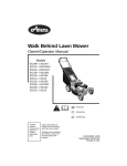
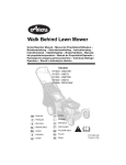
Hydro Pro Series
Owner/Operator Manual – Manuel de L’Opérateur – Betriebsanleitung – Gebruikshandleiding – Instruktionsbog – Instruktionsbok –
Käyttöohjekirja – Brukerhåndbok – Manuale del proprietario/operatore – Manual del operador/propietario – Manual do Proprietário/
Operador – Руководство владельца/пользователя – Instrukcja
Obsługi / Operatora -
988316 - HR1536FXPCE
988319 - HR1544FXPCE (Rear Discharge)
988320 - HE1748FLPCE
ENGLISH
FRANÇAIS
DEUTSCH
NEDERLANDS
DANSK
SVENSKA
SUOMI
NORSK
ITALIANO
ESPAÑOL
PORTUGUESE
RUSSIAN
POLISH
00380400A 3/05
Printed in USA
EC DECLARATION OF CONFORMITY ISSUED BY THE MANUFACTURER – DÉCLARATION DE
CONFORMITÉ CE ÉMISE PAR LE FABRICANT – EU-ÜBEREINSTIMMUNGSERKLÄRUNG DES
655 West Ryan Street
HERSTELLERS – VERKLARING VAN OVEREENSTEMMING VOOR DE EU, AFGEGEVEN DOOR
P.O. Box 157
DE FABRIKANT – EF OVERENSSTEMMELSESERKLÆRING UDSTEDT AF FABRIKANTEN –
Brillion, Wisconsin 54110-0157 DICHIARAZIONE DI CONFORMITÀ CE RILASCIATA DAL PRODUTTORE – DECLARACIÓN DE
CONFORMIDAD CE EMITIDA POR EL FABRICANTE – EF-SAMSVARSERKLÆRING FRA
USA
PRODUSENTEN – EG-DEKLARATIONEN OM ÖVERENSSTÄMMELSE UTFÄRDAD AV
Telephone (920) 756-2141
TILLVERKAREN – VALMISTAJAN ANTAMA EY-VAATIMUSTENMUKAISUUSVAKUUTUS –
DEKLARACJA ZGODNOŚCI Z PRZEPISAMI EC WYDANA PRZEZ PRODUCENTA –
Facsimile (920) 756-2407
DECLARAÇÃO DE CONFORMIDADE CE EMITIDA PELO FABRICANTE –
Ariens Company
We the undersigned, ARIENS COMPANY, certify that: Nous, soussignés ARIENS COMPANY, certifions que : Der Unterzeichnete,
ARIENS COMPANY, bescheinigt, dass: Wij, de ondergetekenden, ARIENS COMPANY, verklaren dat: Undertegnede, ARIENS
COMPANY, attesterer, at: La sottoscritta società ARIENS COMPANY certifica che: Nosotros, los abajo firmantes, ARIENS
COMPANY, certificamos que: Undertegnede, ARIENS COMPANY, bekrefter at: Undertecknad, ARIENS COMPANY, intygar att:
Allekirjoittanut, ARIENS COMPANY, vakuuttaa, että: My, niżej podpisani, ARIENS COMPANY, oświadczamy, że: Nós, abaixo
assinados, certificamos em nome da ARIENS COMPANY, que:
Type: Type : Typ: Type: Walk Behind Lawn Mower – Tondeuse à gazon autotractée – Handgeführter Rasenmäher –
Type: Tipo: Tipo: Type: Duwgrasmaaier – Selvkørende plæneklipper – Tosaerba semovente – Cortacésped de empuje
Typ: Tyyppi: Typ: Tipo: manual – Gressklipper – Självgående gräsklippare – Käsinohjailtava ruohonleikkuri – Kosiarka
trawnikowa – Cortador de Relva Convencional –
Trade Name: Appellation commerciale : Handelsbezeichnung:
Ariens
Handelsnaam: Firmanavn: Nome commerciale: Nombre comercial:
988316
988319
988320
Handelsnavn: Handelsbeteckning: Kauppanimi: Nazwa handlowa:
Nome da Marca:
Model: Modèle : Modell: Model: Model: Modello: Modelo: Modell:
Modell: Malli: Model: Modelo:
Cutting Width: Largeur de coupe : Schnittbreite: Maaibreedte:
Klippebredde: Larghezza di taglio: Ancho de corte: Klippebredde:
Klippbredd: Leikkuuleveys: Szerokość cięcia: Largura de corte:
89.5 cm
111.8 cm
120 cm
Conforms to: Est conforme à : Mit den Anforderungen der folgenden Richtlinien übereinstimmt: Voldoet aan: Er i overensstemmelse med: È
conforme a: Cumple con: Er i samsvar med: Överensstämmer med: Täyttää seuraavat vaatimukset: Jest zgodny z: De acordo com:
98/37/EC, 89/336/EEC;
2000/14/EC Conformity Assessment Annex VI. Annexe VI de l'évaluation de conformité. Konformitätsbewertung, Anhang VI. Bijlage VI
voor beoordeling van overeenstemming. Vurdering af overensstemmelse Anneks VI. Annesso VI della valutazione di conformità. Anexo
VI de la evaluación de la conformidad. Samsvarsvurdering etter vedlegg VI. Bedömning av överensstämmelse Bilaga VI.
Vaatimustenmukaisuuden arviointi, liite VI. Dodatek VI, Ocena zgodności. Anexo VI da Avaliação de Conformidade.
Representative Measured Sound Power Level (Lwa) – Niveau de puissance
acoustique représentatif mesuré (Lwa) – Repräsentativer gemessener
Geräuschpegel (Lwa) – Representatief gemeten geluidsniveau (Lwa) –
Repræsentativt, målt støjeffektniveau (Lwa) – Livello di potenza sonora
rappresentativo rilevato (Lwa) – Nivel de potencia acústica representativo
medido (Lwa) – Representativt målt lydeffektnivå (Lwa) – Representativ uppmätt
ljudnivå (Lwa) – Tyypillinen mitattu äänitehotaso (Lwa) – Zmierzony
reprezentatywny poziom mocy akustycznej (Lwa) – Nível de Potência de Som
Medido Representativo (Lwa)
Guaranteed Sound Power Level (Lwa) – Niveau de puissance acoustique
garanti (Lwa) – Garantierter Geräuschpegel (Lwa) – Gegarandeerd
geluidsniveau (Lwa) – Garanteret støjeffektniveau (Lwa) – Livello di potenza
sonora garantito (Lwa) – Nivel de potencia acústica garantizado (Lwa) –
Garantert lydeffektnivå (Lwa) – Garanterad uppmätt ljudnivå (Lwa) – Taattu
äänitehotaso (Lwa) – Gwarantowany reprezentatywny poziom mocy
akustycznej (Lwa) – Nível de Potência de Som Garantido (Lwa) –
988316
99 dBA
988316
100 dBA
988319
100 dBA
988319
100 dBA
988320
104 dBA
988320
105 dBA
2
Notified Body – Organisme notifié – Zertifizierungsstelle –
Aangemelde instantie – Bemyndiget organ – Organismo
notificato – Organismo notificado – Teknisk kontrollorgan –
Anmält organ – Ilmoitettu laitos – Organ zaświadczający –
Organismo Certificador –
SNCH
11, Route de Luxembourg
L-5230 Sandweiler
3/14/2005
Fred J. Moreaux:
Quality and Conformance Manager (Keeper of Technical File)
Responsable de la qualité et de la conformité des produits
(Dépositaire de la fiche technique) Manager Qualitätssicherung
und Konformität (Archivar der technischen Akte) Kwaliteits- en
normalisatiemanager (Beheerder van technische bestand) Chef
for kvalitet og overensstemmelse (Indehaver af tekniske data)
Responsabile della qualità e della conformità del prodotto
(Depositario del file tecnico) Gerente de calidad y conformidad
(Depositario del archivo técnico) Kvalitet- og samsvarsansvarlig
(innehaver av teknisk fil) Chef för kvalitet och
produktöverensstämmelse (Innehavare av tekniska data)
Laadusta ja vaatimustenmukaisuudesta vastaava johtaja
(Teknisen tiedoston haltija) Kierownik do spraw jakości i
zgodności (Przechowujący Dokumentację Techniczną) Gestor
de Qualidade e Conformidade (Zelador de Arquivos Técnicos)
Ariens Company
Brillion, WI 54110-0157 USA
Signature Signature Unterschrift
Handtekening Underskrift Firma
Firma Signatur Namnteckning
Allekirjoitus Podpis Assinatura
Date Date Datum
Datum Dato Data
Fecha Dato Datum
Päiväys Data Data
CE, melu ja tärinä – CE Dźwięku i Wibracji – Som e
Vibração CE – (Ref. EN836-2001)
CE Sound and Vibration – Bruits et vibrations CE –
CE Geräusch- und Vibrationswerte – CE Geluid en
trilling – CE støj og vibration – Livello sonoro e
vibrazioni CE – Sonido y vibración CE – CE-lyd og
-vibrasjon – CE ljudnivå och vibrationer –
Model: Modèle : Modell: Model: Model: Modello: Modelo: Modell: Modell: Malli:
Model: Modelo:
Oper. Ear Sound Pressure (Lpa) in dBA – Pression acoustique aux oreilles de l’opérateur
(Lpa) en dBA – Geräuschpegel am Ohr des Bedieners (Lpa) in dBA – Geluidsdruk bij het
oor van de gebruiker (Lpa) in dBA – Strøjtryk ved brugerens øre (Lpa) målt i dBA –
Pressione sonora all’orecchio dell’operatore (Lpa) in dBA – Presión de sonido en el oído
(Lpa) in dBA – Lydtrykk ved førerens øre (Lpa) inn dBA – Ljudeffekt vid förarens öron (Lpa)
i dBA – Kuljettajan korvaan kohdistuva äänenpaine (Lpa), dBA – Robocze ciśnienie
akustyczne na uchu (Lpa) w decybelachA – Oper. Pressão do Som no Ouvido (Lpa) em
dBA –
Vibration Measure (m/sec2) at Operator Mesure des vibrations (m/s2) au niveau de
l’opérateur Vibration (m/s2) an des Bedieners Gemeten trilling bij (m/sec2)
Vibrationsmålinger (m/s2) ved brugerens Vibrazioni percepite dall’operatore (m/sec2)
Medida de vibración (m/seg2) en el operador Vibrasjonsmåling (m/s2) ved førerens
Vibrationsmått (m/s2) vid förarens Tärinä (m/s2) kuljettajan Pomiar wibracji (m/sec2) u
operatora Medida de Vibração (m/seg.2) no Operador
Hands – Mains – Hände – De handen van de gebruiker – Hænder – Mani – Manos –
Hender – Händer – Käsissä – Ręce – Mãos –
X
Y
Z
3
988316
988319
988320
87
86
89
1.8
2.0
1.6
1.3
2.1
3.2
1.8
1.6
1.8
TABLE OF CONTENTS
Safety . . . . . . . . . . . . . . . . . . . . . . . . . . . . . . . . . . . . . . 5
Service and Adjustments . . . . . . . . . . . . . . . . . . . . . 17
Assembly . . . . . . . . . . . . . . . . . . . . . . . . . . . . . . . . . . . 9
Storage . . . . . . . . . . . . . . . . . . . . . . . . . . . . . . . . . . . . 23
Controls and Features. . . . . . . . . . . . . . . . . . . . . . . . 10
Troubleshooting . . . . . . . . . . . . . . . . . . . . . . . . . . . . 23
Operation . . . . . . . . . . . . . . . . . . . . . . . . . . . . . . . . . . 11
Service Parts . . . . . . . . . . . . . . . . . . . . . . . . . . . . . . . 24
Maintenance Schedule . . . . . . . . . . . . . . . . . . . . . . . 16
Specifications . . . . . . . . . . . . . . . . . . . . . . . . . . . . . . 25
INTRODUCTION
THE MANUAL
Customer Note: If the Dealer does not register your
product, please fill out, sign and return the product
registration card to Ariens or go to www.ariens.com on the
internet.
Before operation of unit, carefully and completely read your
manuals. The contents will provide you with an
understanding of safety instructions and controls during
normal operation and maintenance.
UNAUTHORIZED REPLACEMENT PARTS
All reference to left, right, front, or rear are given from
operator standing in operation position and facing the
direction of forward travel.
MODEL AND SERIAL NUMBERS
Transfer
model & serial
number label
from product
registration
here.
When ordering replacement parts or
making service inquiries, know the Model
and Serial numbers of your unit and
engine.
Numbers are located on the product
registration form in the unit literature
package. They are printed on a serial
number label, located on the frame of
your unit.
Serial
Number
Label
Use only Ariens replacement parts. The replacement of any
part on this vehicle with anything other than an Ariens
authorized replacement part may adversely affect the
performance, durability, or safety of this unit and may void
the warranty. Ariens disclaims liability for any claims or
damages, whether warranty, property damage, personal
injury or death arising out of the use of unauthorized
replacement parts. To locate your nearest Ariens Dealer, call
1-920-756-4664 or go to www.ariens.com on the internet.
DISCLAIMER
Ariens reserves the right to discontinue, make changes to,
and add improvements upon its products at any time without
public notice or obligation.The descriptions and
specifications contained in this manual were in effect at
printing. Equipment described within this manual may be
optional. Some illustrations may not be applicable to your
unit.
DEALER DELIVERY
Dealer should:
1. Check all controls for proper function.
2. Check the safety interlock system to make sure that it
is functioning properly. (See Check Safety Interlock
System on page 11.)
Figure 1
•
3. Fill out Original Purchaser Registration Card and
return the card to Ariens.
OG1400
Record Engine Model and Serial numbers here.
4. Explain Limited Warranty Policy.
5. Explain recommended lubrication and maintenance.
Advise customer on adjustments.
6. Instruct customer on controls and operation of unit.
Discuss and emphasize the Safety Precautions. Give
customer Owner/Operator, Parts, and Engine
Manuals. Advise customer to thoroughly read and
understand them.
PRODUCT REGISTRATION
The Ariens dealer must register the product at the time of
purchase. Registering the product will help the company
process warranty claims or contact you with the latest
service information. All claims meeting requirements during
the limited warranty period will be honored, whether or not
the product registration card is returned. Keep a proof of
purchase if you do not register your unit.
GB-4
© Copyright 2005 Ariens Company
SAFETY
PRACTICES AND LAWS
WARNING: This cutting machine is capable
of amputating hands and feet and throwing
objects. Failure to observe the safety
instructions in the manuals and on decals
could result in serious injury or death.
Practice usual and customary safe working precautions, for
the benefit of yourself and others. Understand and follow all
safety messages. Be alert to unsafe conditions and the
possibility of minor, moderate, or serious injury or death.
Learn applicable rules and laws in your area, including those
that may restrict the age of the operator.
Slopes are a major factor related to
loss-of-control and tip-over accidents.
Operation on all slopes requires extra
caution.
REQUIRED OPERATOR TRAINING
Original purchaser of this unit was instructed by the seller on
safe and proper operation. If unit is to be used by someone
other than original purchaser; loaned, rented or sold,
ALWAYS provide this manual and any needed safety
training before operation.
Tragic accidents can occur if the operator is
not alert to the presence of children. Never
assume that children will remain where you
last saw them.
Gasoline is extremely flammable and the
vapors are explosive, handle with care.
SAFETY DECALS AND LOCATIONS
Disengage attachment, stop unit and engine,
remove key, engage parking brake, and allow
moving parts to stop before leaving
operator’s position.
ALWAYS replace missing or damaged Safety Decals. Refer
to figures below for Safety Decal locations.
1
SAFETY ALERTS
Look for these symbols to point out important
safety precautions. They mean:
2
Attention!
Personal Safety Is Involved!
4
Become Alert!
2
Obey The Message!
The safety alert symbols above and signal words below are
used on decals and in this manual.
Read and understand all safety messages.
3
DANGER: IMMINENTLY HAZARDOUS
SITUATION! If not avoided, WILL RESULT
in death or serious injury.
Figure 2
OG1820
1
WARNING: POTENTIALLY HAZARDOUS
SITUATION! If not avoided, COULD
RESULT in death or serious injury.
CAUTION: POTENTIALLY HAZARDOUS
SITUATION! If not avoided, MAY RESULT in
minor or moderate injury. It may also be
used to alert against unsafe practices.
2
4
NOTATIONS
2
NOTE: General reference information for proper operation
and maintenance practices.
IMPORTANT: Specific procedures or information required to
prevent damage to unit or attachment.
GB - 5
Figure 3
OG2050
1. Danger! To avoid serious injury or death
3. Warning!
Read the operator’s manual.
Always stand clear of discharge.
OL0910
OL1801
Keep children and others away from unit
while operating.
DO NOT operate mower unless guards are in
operating position or bagger is attached.
OL3320
OL4370
Never direct discharge toward other people.
Thrown objects can cause injury.
4. Danger!
Stay clear of rotating parts.
OL0910
•
Keep safety devices (guards, shields, switches, etc.)
in place and working.
•
Check interlock system per manual before use.
•
Never allow operation by untrained persons.
•
When parking on a slope always engage parking
brake.
•
Disengage PTO, stop unit and engine, set parking
brake and remove key before making any
inspections, repairs, etc.
2. Danger! Rotating Blades
ROTATING BLADE! Keep hands and feet
away.
OL5100
SAFETY RULES
Read, understand and follow all safety practices in
Owner/Operator Manual before beginning assembly. Failure
to follow instructions could result in personal injury and/or
damage to unit.
ALWAYS remove key (if equipped) and disconnect wire from
spark plug before assembly. Unintentional engine start up
can cause death or serious injury.
Complete a walk around inspection of unit and work area to
understand:
OL3030
OL0910
Work area
•
Your unit
•
All safety decals
Always stand clear of discharge area. DO NOT
direct discharge toward other people. Remove
objects that could be thrown by the blade. DO
NOT operate mower over gravel and hard
surfaces.
ALWAYS check overhead and side clearances carefully
before operation.
Keep people and pets away when operating
unit. Keep children out of the work area and
under the watchful care of a responsible adult.
Keep children out of work area and under watchful care of a
responsible adult.
Shut off engine, remove key, read manual
before you unplug, adjust or repair unit.
Check for weak spots on docks, ramps or floors. Avoid
uneven work areas and rough terrain.
OL4370
ALWAYS be aware of traffic when operating along streets or
curbs.
Keep children and people away.
Keep area of operation clear of all toys, pets, and debris.
Thrown objects can cause injury.
ALWAYS be sure of your footing. Keep a firm hold on
handlebar. Walk, NEVER run.
OL4010
NO STEP! Always keep feet away from
rotating parts.
OL4420
•
DO NOT operate on wet grass.
Dust, smoke, fog, etc. can reduce vision and cause an
accident. Operate unit only when there is good visibility and
light.
GB-6
Read the entire Owner/Operator manual and other training
material. If the operator or the mechanic cannot read the
manual, it is the owner’s responsibility to explain it to them.
Only the user can prevent and is responsible for accidents or
injuries occurring to themselves, other people or property.
•
Only trained adults may operate or service unit
•
Training includes actual operation
NEVER modify or remove safety devices.
ALWAYS keep discharge cover or complete grass catcher in
place and in proper working condition.
Check steering control operation frequently. Adjust and
service as required.
Safety Interlock System must function properly. DO NOT
operate unit if operator presence control is damaged or
disabled.
NEVER allow children to operate or play on or near unit.
Be alert and shut off unit if children enter area.
Never carry passengers.
NEVER operate unit after or during the use of medication,
drugs or alcohol. Safe operation requires your complete and
unimpaired attention at all times.
NEVER allow anyone to operate this unit when their
alertness or coordination is impaired.
Wear adequate safety gear, protective gloves and footwear.
NEVER wear open sandals or canvas shoes during
operation.
If you strike an object, or if equipment vibrates abnormally,
stop engine at once, disengage PTO, wait for all moving
parts to stop, and remove key. Check for any damage or
loose parts. Repair before restart.
Before starting engine: disengage PTO, engage parking
brake and place unit in neutral.
DO NOT operate at too fast a rate. DO NOT change engine
governor settings or over-speed engine. Slow down and turn
corners slowly.
Disengage PTO when attachment is not in use. DO NOT
raise deck with blades running. ALWAYS turn off power to
attachment when travelling, crossing driveways, etc.
Protect eyes, face and head from objects that may be
thrown from unit. Wear appropriate hearing protection.
Avoid uneven and rough terrain. DO NOT operate near
drop-offs, ditches, or embankments. Unit can suddenly turn
over if a wheel is over the edge of a cliff or ditch, or if an
edge caves in.
Sharp edges can cut. Moving parts can cut off fingers or a
hand. Wrap blade(s), wear sturdy gloves and use extreme
caution when servicing. On multi-blade mowers, rotation of
one blade will cause all blades to rotate.
DO NOT try to stabilize unit by putting foot on ground when
operating with applicable riding attachments.
ALWAYS keep hands and feet away from all rotating parts
during operation. Rotating parts can cut off body parts.
ALWAYS keep hands away from all pinch points.
DO NOT touch unit parts which might be hot from operation.
Allow parts to cool before attempting to maintain, adjust or
service.
NEVER place your hands or any part of your body or
clothing inside or near any moving part while unit is running.
DO NOT wear loose clothing or jewelry. Tie back hair that
may get caught in rotating parts.
When engine is running and speed control lever is forward,
holding only one steering lever will cause unit to circle
around one drive wheel.
Use care when approaching blind corners, shrubs, trees or
other objects that may obscure view.
ALWAYS disengage PTO, stop unit and engine, set parking
brake, remove key and allow moving parts to stop before
clearing clogs or cleaning unit.
Keep children and people away from unit during operation.
Never leave a running unit unattended. ALWAYS shut off
engine before leaving unit.
Fumes from engine exhaust can cause injury or death.
ALWAYS remove key to prevent unauthorized use.
DO NOT run engine in an enclosed area. Always provide
good ventilation.
DO NOT operate in reverse unless absolutely necessary.
ALWAYS backup slowly. ALWAYS look down and behind,
before and while backing.
Thrown objects can cause injury and property damage. DO
NOT point discharge at anyone or discharge directly onto
paved or gravel surfaces.
Always stand clear of the discharge area when operating
this unit.
Read, understand, and follow all instructions in the manual
and on the machine before starting. Understand:
•
How to operate all controls
•
The functions of all controls
•
How to STOP in an Emergency
•
Braking and steering characteristics
•
Turning radius and clearance
ALWAYS keep protective structures, guards, and panels in
good repair, in place and securely fastened.
DO NOT operate on steep slopes. DO NOT operate on
slopes of more than 10°. Operate across the face of slopes,
not up and down.
Turf conditions can affect the unit’s stability.
Keep all movement on slopes slow and gradual. DO NOT
make sudden changes in speed or direction. Use a slow
speed to avoid stopping or shifting on slopes. Avoid starting
or stopping on a slope.
DO NOT park unit on a slope unless absolutely necessary.
When parking on a slope always engage parking brake and
block wheels.
Use extra care when loading or unloading unit onto trailer or
truck.
GB - 7
Secure unit chassis to transport vehicle. NEVER secure
from rods or linkages that could be damaged.
DO NOT transport machine while engine is running.
Keep unit free of grass, leaves, or other debris. Clean up oil
or fuel spills.
This product is equipped with an internal combustion engine.
DO NOT use on or near any unimproved, forest covered or
brush covered land unless the exhaust system is equipped
with a spark arrester meeting applicable local, state or
federal laws. A spark arrester, if used, must be maintained in
effective working order by the operator.
Fuel is highly flammable and its vapors are explosive.
Handle with care. Use an approved fuel container.
No smoking, No sparks, No flames. ALWAYS allow engine to
cool before servicing.
NEVER fill fuel tank when engine is running or hot from
operation.
California to cause cancer and reproductive harm. Wash
hands after handling.
Reverse connections may cause sparks which may result in
injury. ALWAYS connect/disconnect cables in proper order.
Poisonous battery fluid contains sulfuric acid and its contact
with skin, eyes, or clothing can cause severe burns.
Explosive Gases! No flames, No sparks, No smoking near
battery.
ALWAYS wear safety glasses and protective gear near
battery.
ALWAYS keep batteries out of reach of children.
Before making any inspections, repairs, etc.: disengage
PTO, stop unit and engine, set parking brake, remove key,
allow moving parts to stop.
ALWAYS keep body and hands away from pin holes or
nozzles which eject hydraulic fluid under pressure.
Allow hot parts to cool.
NEVER fill or drain fuel tank indoors.
ALWAYS block wheels, engage parking brake and know all
jack stands are strong, secure and will hold weight of unit
during maintenance.
Replace fuel cap securely and clean up spilled fuel.
Never fill containers inside a vehicle or on a truck or trailer
bed with a plastic liner. Always place containers on the
ground away from your vehicle before filling.
An extension spring, when extended, stores energy and can
be dangerous. Always use tools specifically designed for
installing or removing an extension spring. Always compress
or extend springs slowly.
When practical, remove gas-powered equipment from the
truck or trailer and refuel it on the ground. If this is not
possible, then refuel such equipment on a trailer with a
portable container, rather than from a gasoline dispenser
nozzle.
ALWAYS maintain unit in safe operating condition. Damaged
or worn out muffler can cause fire or explosion.
Keep hardware, especially blade attachment bolts, tight.
Keep the nozzle in contact with the rim of the fuel tank or
container opening at all times until fueling is complete. Do
not use a nozzle lock-open device.
Maintain or replace safety and instruction labels, as
necessary.
For unit storage or extended storage:
If fuel is spilled on clothing, change clothing immediately.
NEVER store fuel inside where there is an open flame, such
as a water heater.
Avoid Electric Shock. Objects contacting both battery
terminals at the same time may result in injury and unit
damage. DO NOT reverse battery connections.
Explosive Gases from battery can cause death or serious
injury. Poisonous battery fluid contains sulfuric acid and its
contact with skin, eyes or clothing can cause severe
chemical burns.
NEVER store with fuel in fuel tank, inside a building
where any ignition sources are present.
•
Allow engine to cool completely.
Use only attachments or accessories designed for your unit
and that can be used safely on your terrain.
Reverse connections may result in sparks which can cause
serious injury. Always connect positive (+) lead of charger to
positive (+) terminal, and negative (-) lead to negative (-)
terminal.
ALWAYS disconnect negative (-) cable FIRST and positive
(+) cable SECOND. ALWAYS connect positive (+) cable
FIRST, and negative (-) cable SECOND.
•
Check attachment components frequently for wear, damage
or deterioration. Replace with manufacturer’s recommended
parts for safety.
To reduce fire hazard and overheating, keep equipment free
of grass, leaves, debris or excessive lubricants.
Use extra care with grass catchers and other attachments.
These can change the stability of the unit. Use only
approved hitch points.
ALWAYS be aware of attachments when turning. ALWAYS
allow adequate clearance between attachments, personnel,
and other objects.
No flames, No sparks, No smoking near battery.
ALWAYS wear safety glasses and protective gear near
battery. Use insulated tools.
DO NOT TIP battery beyond a 45° angle in any direction.
Battery posts, terminals and related accessories contain
lead and lead compounds, chemicals known to the State of
GB-8
ASSEMBLY
WARNING: AVOID INJURY. Read and
understand the entire Safety section before
proceeding.
1. Remove the unit from shipping container.
2. Adjust tire pressure to 8 to 16 psi (55 to 110 kPa).
3. Service and connect battery. See Charge Battery on
page 21.
4. Check the adjustments outlined in Service &
Adjustments.
5. Check engine oil level. See engine manual.
6. Check hydraulic fluid level. See Maintenance.
7. Add clean fuel to the fuel tank. See engine manual for
type and grade.
8. Check for loose hardware.
9. Be sure that safety interlock system operates correctly.
See Check Safety Interlock System on page 11.
10. Be sure that unit tracks straight.
Unit must not pull sharply to the left or right when the
speed control levers are pushed quickly forward.
Unit must not pull sharply to the left or right when the
steering levers are released. See TRACKING
ADJUSTMENT on page 18.
GB - 9
CONTROLS AND FEATURES
13
15
6
19
3
9
14
11
2
7
16
1
10
1
14
12
4
18
17
Figure 4
1. Operator Presence Control Lever
11. Ignition Switch
2. Parking Brake
12. Bypass Valve Levers
3. Choke Control
13. Control Levers
4. Throttle Lever
14. Control Stop Lock Lever
5. PTO Switch
15. Pivot Bar
6. Hourmeter
16. Muffler Guard
7. Fuel Cap
17. Mower Lock Pin
8. Hydraulic Fluid Tank
18. Oil Light (988320)
9. Recoil Starter Handle
19. Battery (988320)
10. Cold Start Disengage
GB-10
8
5
12
SAFETY INTERLOCK SYSTEM
DANGER: SAFETY INTERLOCK SYSTEM
FAILURE and improper operation of unit can
result in death or serious injury. ALWAYS know
the safety interlock system is operating
properly. See Check Safety Interlock System on
page 11 for testing instructions.
A
B*
C
ENGINE
See Figure 4 for controls and features locations.
PTO
CONTROLS AND FEATURES
OPERATOR
PRESENCE CONTROL
WARNING: AVOID INJURY. Read and
understand the entire Safety section before
proceeding.
PARKING BRAKE
ENGINE RUNNING TEST
OPERATION
On
Off
Won’t
Engage
Runs
On
Off
Disengages
Runs
Off
On
Engages
Runs
D*
Off
Off**
Engaged
Stops
Running
E
Off
Off
Off
Stops
Running
*Perform this test with PTO properly engaged.
Check Safety Interlock System
**Release both operator presence controls for this test.
Test the safety interlock system at each operation. If the
system does not function properly, do not operate the unit
until repairs are made.
The engine will only start with the PTO disengaged, the
speed control levers in neutral and the parking brake on.
NOTE: PTO should only engage when the parking brake is
off AND at least one operator presence control is engaged.
PTO should disengage when BOTH operator presence controls are released.
To test:
Operator Presence Control
The operator presence control levers must be depressed to
operate the PTO. When the PTO is engaged, releasing the
operator presence control levers stops the mower blades.
1. With engine off, set controls as listed in line A of the
table below and try to start the engine.
IMPORTANT: If the system does not function properly, do
not operate the unit until repairs are made.
CAUTION: AVOID INJURY. Operate only when
operator presence control is functioning
correctly. See Check Safety Interlock System on
page 11 for testing instructions.
ENGINE
Control Levers
PTO
PRESENCE CONTROL*
OPERATOR
PARKING BRAKE
ENGINE OFF TEST
2. Repeat step 1 for lines B-E of the table.
Off
Starts
WARNING: AVOID INJURY. When the engine is
running , moving only one lever causes the unit
to circle around one drive wheel.
ALWAYS move levers slowly.
A
On
B
On
Off
Off
Starts
C
Off
Off
Off
Doesn’t Start
D
Off
On
Off
Doesn’t Start
The control levers are used to steer, operate in forward and
reverse, and stop the unit. Push forward to move forward.
Pull back to move in reverse.
E
Off
Off
On
Doesn’t Start
Ignition Switch (988320)
On
*Test the left and right operator presence controls
separately.
1
3. With engine running, set controls as listed in line A of
the table below and check the result.
IMPORTANT: If the system does not function properly, do
not operate the unit until repairs are made.
4. Repeat step 3 for lines B-E of the table.
GB - 11
2
3
OF1210
Operate the ignition switch with the removable
key. The switch has three positions: Off (1), On
(2) and Start (3). To start the engine, turn the
key to Start, then release to On. To stop the
engine, turn the key to Off.
Ignition Switch (988316, 319)
OF1212
Recoil Starter Handle
Pull the recoil starter handle to start the engine.
Operate the ignition switch with the removable
key. The switch uses two positions: Off (1) and
On (2). To start the engine, turn the key to On
(2) and pull the recoil handle. To stop the
engine, turn the key to Off (1).
Hour Meter
Recoil Start: The hour meter measures the
number of hours the engine has been run.
OG0620
Throttle Lever
1
The throttle lever changes the speed of the
engine. Move the throttle lever to Fast (1) to
increase engine speed. Move the lever to Slow
(2) to decrease engine speed.
Oil Pressure Light (988320)
OG0600
2
The red light near this symbol comes on when
the engine is running and engine oil pressure is
low. Check oil level and add if necessary. See
Engine Manual.
Cold Start Disengage
OG1180
Use the cold start disengage for easier starting on cold days.
Choke Control
1. Pull out cold start chain 1 to 4 links and lock chain in
frame notch (Figure 5).
Use the choke control to start a cold engine. Pull
the control out to choke the engine. Push the
control in when the engine gets warm.
2. Start engine and allow engine to warm to operating
temperature.
OG1190
3. Slowly release chain from notch.
PTO Clutch
WARNING: AVOID INJURY. Unit will move if
steering controls are engaged when cold start
feature is released.
1
Notch
2
3
OE0261
Pull the PTO (power take off) switch past On (1) to Reset (2)
to engage the mower blades. Push the PTO switch Off (3) to
disengage the mower blades.
NOTE: Pull PTO switch to Reset (2) to engage mower
blades after operator presence control has been released.
Cold Start
Disengage
Parking Brake
Figure 5
The parking brake holds the tractor in position
when not in use.
2
OG1320
To engage parking brake, pull the brake handle
back (1).
FILL FUEL TANK
To release parking brake, push the brake handle
forward (2).
WARNING: Fuel is highly flammable and its
vapors are explosive. Handle with care. Use an
approved fuel container.
NO smoking, NO sparks, NO flames. ALWAYS
allow engine to cool before servicing.
NEVER fill fuel tank when engine is running or
hot from operation.
NEVER fill or drain fuel tank indoors.
Replace fuel cap securely and clean up spilled
fuel.
1
GB-12
Add fuel to the fuel tank as needed. See engine manual for
type and grade of fuel.
To add fuel to the fuel tank:
1. Put the unit in an open area.
IMPORTANT: DO NOT operate starter motor more than 15
seconds per minute, as overheating and damage can occur.
If engine will not start, refer to Troubleshooting or Engine
Manual.
7. When the engine starts, release the key to Run
position.
2. Stop the engine.
3. Allow engine to cool.
8. After engine starts, adjust choke as needed. Allow
engine to warm and run smoothly before operating
unit.
4. Clean the fuel cap and the area around the fuel cap to
prevent dirt from entering the fuel tank.
5. Remove the cap from the fuel tank.
Shut Off
6. Fill the fuel tank. Be careful not to spill.
1. Bring control levers to neutral.
7. Install the cap on the fuel tank and tighten.
2. Move the throttle lever to Slow.
8. Clean up any spilled fuel before starting the engine.
3. Engage parking brake.
4. Turn the ignition key Off.
TO STOP IN AN EMERGENCY
5. Allow engine to stop completely.
1. Release operator presence control(s).
2. Turn the ignition key Off.
TO OPERATE UNIT
3. Allow engine to stop completely.
Operate the unit only in the operator’s position directly
behind the handlebars.
4. Engage parking brake.
To operate:
STARTING AND SHUT OFF
Before Each Use
1. Start the engine (See STARTING AND SHUT OFF on
page 13).
Check each item in Each Use in the Maintenance Schedule.
2. Move the throttle lever to the Fast position.
Recoil Start
3. Engage operator presence control.
1. Engage the parking brake.
WARNING: AVOID INJURY. When the engine
is running , using one steering control lever
causes the unit to circle around one drive
wheel.
2. Bring control levers to neutral.
3. Move PTO switch to Off.
4. Set throttle to the proper starting position. If the engine
is cold, choke the engine.
ALWAYS hold both steering levers when
operating unit and move levers slowly.
5. Turn ignition switch to On.
6. Grasp recoil starter handle and pull rope out slowly
until it pulls harder. This is the compression stroke.
•
7. Let the rope rewind slowly.
To move straight forward, slowly push control levers
forward.
8. Pull rope with rapid continuous full arm stroke to start
engine. Allow rope to rewind slowly.
IMPORTANT: DO NOT let starter handle snap against
engine.
9. Repeat until engine starts. (If engine does not start,
refer to Engine Manual.)
OG1600
•
10. After engine starts, adjust choke as needed. Allow
engine to warm and run smoothly before operating
unit.
To stop unit motion, allow control levers to return to
neutral.
Electric Start (988320)
To start the engine:
1. Engage parking brake.
OG1610
2. Bring control levers to neutral.
3. Move PTO switch to Off.
4. If the engine is cold, choke the engine.
5. Move the throttle to Fast.
6. Put the ignition key in the switch and turn it to Start.
GB - 13
•
CUTTING HEIGHT ADJUSTMENT
To turn to the left, push the right hand control lever
forward.
Fixed Decks
1. Shut off the unit. See Shut Off on page 13 and "To stop
mowing."
2. Lift deck by handle until mower lock pins can be pulled
out of holes.
3. Turn latches slightly so they can’t snap back into place.
OG1630
•
4. Set deck to desired cutting height (Figure 6).
To turn to the right, push the left hand control lever
forward.
5. Place mower lock pins into desired hole.
IMPORTANT: Make sure lock pins are fully engaged.
6. Repeat adjustment for other side of deck.
Fixed Deck Cutting Heights
OG1640
•
To move in reverse, pull both control levers backward,
past the neutral position. Pulling the levers farther back
increases reverse speed.
OG1650
Figure 6
WARNING: Uncontrolled reverse travel can
result in serious injury.
Floating Decks (988320)
1. Shut off the unit. See Shut Off on page 13 and "To stop
mowing."
Do not put control levers into the reverse
position unless you are prepared to operate in
reverse.
2. Lift deck by handle until hair pins can be removed from
height adjustment rods.
3. Set deck to desired cutting height (Figure 7).
To mow:
4. Insert hair pins into appropriate holes on height
adjusting rods.
1. Move the throttle lever to the fast position.
2. Engage operator presence control(s).
5. Repeat adjustment for other side of deck.
NOTE: Operator presence control must remain engaged.
3. Move the PTO switch to On to engage mower.
IMPORTANT: NEVER engage the PTO if the mower is
plugged with grass or other material. This will damage the
PTO belt.
OG1380
NOTE: It may be necessary to adjust cutting height in steps
to keep deck from binding.
Floating Deck Cutting Heights
4. Push control levers forward slowly.
When you know how to operate the unit, select a speed
appropriate to your mowing conditions.
To stop mowing:
1. Allow control levers to return to neutral.
2. Move the throttle lever to 1/2 speed.
3. Turn off PTO switch.
Figure 7
GB-14
OG1385
LAWN STRIPER ADJUSTMENT (48" decks)
TO TRANSPORT UNIT
The striper drags behind the deck and shapes grass as you
mow.
Adjust the striper to match cutting height.
ALWAYS shut off engine, remove key and drain fuel when
transporting unit on a truck or trailer. Use extra care when
loading or unloading unit.
Short grass (deck low): mount from bottom holes.
Engage parking brake.
Tall grass (deck high): mount from top holes.
Secure unit chassis to transport vehicle. NEVER secure
from rods or linkages that could be damaged.
PARKING
DO NOT transport machine while engine is running.
1. Shut off the unit. See Shut Off on page 13 and "To stop
mowing."
2. Remove the key.
3. Lock pivot bar against control levers.
4. Chock or block the wheels if parked on a slope.
TO PUSH UNIT BY HAND
To move the unit without the engine running:
1. Rotate the bypass valve levers located on the back
side of the pumps approximately 1/2 turn
counterclockwise.
2. Release parking brake.
3. Push unit to desired location.
4. Rotate the bypass valve levers located on the back
side of the pumps approximately 1/2 turn clockwise to
operate the unit.
IMPORTANT: Towing the unit will damage hydraulic motors.
GB - 15
MAINTENANCE SCHEDULE
Period
Service
Check Safety Interlock System
Task
WARNING: Safety interlock system failure and improper operation of unit
can result in death or serious injury. Test this system each time the unit is
operated. If this system does not function as described, do not operate until
repairs are made. See Check Safety Interlock System on page 11.
Each Use
Check Air Cleaner
Check the air cleaner element before each use. See engine manual for
detailed instructions.
Check Engine Oil
Check the engine oil level before each use. Never operate the engine when
the oil level is low. See engine manual for detailed instructions.
Check Engine Cooling
Check the engine air cooling system before each use. See engine manual for
detailed instructions.
Check Fasteners
Check all nuts, bolts, and other fasteners before each use. Replace missing
or damaged fasteners.
Check Tire Pressure
Check tires for proper inflation, excessive wear or damage before each use.
The correct air pressure is 8 to 16 psi (55 to 110 kPa).
Check Hydraulic Fluid Level
Check hydraulic oil level mark on cap/dipstick. Add 15W-50 synthetic oil as
needed. Do not overfill.
Follow Engine Manual
Maintenance Schedule
Perform scheduled engine maintenance. See engine manual for detailed
instructions.
Check Battery
Keep battery and its terminals clean.
Check All Belts
Replace worn or deteriorated belts.
Every 25
Hours
Mower Blades
Check mower blades for wear. Sharpen or replace as needed.
Clean Air Cleaner Foam
Element
See engine manual for detailed instructions.
Every 50
Hours
General Lubrication
All all pivot points and pin connections. Grease lube fittings.
Change Engine Oil
Open the petcock to drain oil through oil drain hole on the left side of engine.
See engine manual for addional instructions.
Check Fuel Filter
See engine manual for detailed instructions.
Check Spark Plug
See engine manual for detailed instructions.
Check Muffler
Check muffler for damage or wear. Replace if necessary.
Clean Air Cleaner Paper
Element
See engine manual for detailed instructions.
Change Hydraulic Fluid and
Filter
Drain hydraulic tank, replace hydraulic oil filter, refill system.
Every 100
Hours
Every 500
Hours
* Change oil after first 8 hours of operation and every 100
hours thereafter.
** Change Hydraulic Fluid after first 50 hours of operation
and every 500 hours thereafter.
GB-16
SERVICE AND ADJUSTMENTS
2. Remove tank from frame and allow tank to tip rearward
to allow oil to drain from system (Figure 8).
WARNING: AVOID INJURY. Read and
understand the entire Safety section before
proceeding.
3. After most of the oil has drained, turn the tank upside
down counterclockwise to allow the rest of the oil to
drain.
HYDRAULIC FLUID
4. Clean around filter.
5. Turn filter counterclockwise to remove.
WARNING: HYDRAULIC FLUID UNDER
PRESSURE can penetrate skin and cause
severe burns that can result in death or serious
injury.
6. Fill the new oil filter with about 8 oz. (236 ml) of
hydraulic oil.
7. Apply a thin coat of oil onto seal of new filter.
8. Install new filter and hand tighten securely.
ALWAYS keep body and hands away from pin
holes or nozzles which eject hydraulic fluid
under pressure. ALWAYS use paper or
cardboard and not hands to search for leaks.
9. Fill system with about 44 oz. (1.3L) fresh, clean
hydraulic oil. See Specifications for proper type.
10. Run-in hydraulic system to bleed and lubricate
components. See below.
KNOW that all hydraulic fluid connections are
tight and all hydraulic hoses and lines are in
good condition BEFORE applying pressure to
system.
Foreign fluid injected into skin must be
surgically removed within a few hours by a
doctor familiar with this form of injury or
gangrene may result.
Check Hydraulic Fluid Level
Check the hydraulic fluid level with the dipstick before each
use (more often if leaks are observed). Stop the engine
before servicing any hydraulic parts.
FULL Mark
Operating
Range
OE0380
1. Run unit until warm.
2. Shut off engine.
3. Unscrew tank cap to remove cap/dipstick.
NOTE: Do not allow any dirt to get into the system.
4. Wipe dipstick clean.
5. Screw cap/dipstick back into tank.
Figure 8
6. Remove cap/dipstick and check hydraulic oil level
mark.
Hydraulic Run-In Procedure
1. Jack the drive wheels off the floor.
7. Add hydraulic fluid as needed. Do not overfill. See
Specifications for hydraulic fluid type.
2. Start unit. Run engine at slowest speed for 1-2 minutes
to bleed hydraulic pumps.
Change Hydraulic Fluid and Filter
3. Increase engine speed to half. Set speed control 1/3
forward. Run engine for 3-5 minutes to bleed hydraulic
motors.
Change hydraulic fluid and filter after the first 50 hours of
operation. They both should be changed every 500 hours
thereafter.
NOTE: If necessary, start the motors turning by hand.
To change the hydraulic fluid and filter:
4. Shut off engine and lower the unit to the floor.
1. Place open container under tank. The container should
be able to hold at least 4 quarts (3.8 L) of oil.
IMPORTANT: If any squealing noise occurs in the motors,
repeat the run-in procedure.
GB - 17
GENERAL LUBRICATION
Check Reverse Tracking
Apply a small amount of oil to the pivot points as required for
smooth operation (Figure 9).
WARNING: Uncontrolled reverse travel can
result in serious injury.
Apply high quality lithium based grease to all lube fittings
every 50 hours of operation.
Do not put control levers into the reverse
position unless you are prepared to operate in
reverse.
NOTE: The mower spindle assembly is maintenance free.
1
1
2
1. Adjust forward tracking (See Check Forward Tracking
on page 18).
2. Slowly pull both control levers all the way back.
3. Note which direction, if any, the unit pulls.
4. Stop unit and engine.
5. Adjust tracking if needed.
If unit turns to the right:
1. Reduce the air pressure in the left tire.
1
2
2. Increase the air pressure in the right tire.
OG1480
3. Turn the reverse stop bolt on the right neutral
adjustment bracket counterclockwise to speed up the
right wheel.
1
1. Wheel Bearings
2. Flange Bushings
4. Check reverse tracking and adjust as needed.
Figure 9
If unit turns to the left:
1. Reduce the air pressure in the right tire.
TRACKING ADJUSTMENT
2. Increase the air pressure in the left tire.
Check Forward Tracking
2. Slowly push both control levers against the pivot bar.
3. Turn the reverse stop bolt on the right neutral
adjustment bracket clockwise to slow down the right
wheel.
3. Note which direction, if any, the unit pulls.
4. Check reverse tracking and adjust as needed.
1. Start engine and run unit at full throttle.
4. Stop unit and engine.
5. Adjust tracking if needed.
1
Try each of the following steps until the unit tracks straight. It
may not be necessary to perform all the steps.
If unit turns to the right:
1. Reduce the air pressure in the left tire.
2
2. Increase the air pressure in the right tire.
3. Adjust the clevis on the right steering control rod down
the rod.
If unit turns to the left:
1. Reduce the air pressure in the right tire.
2. Increase the air pressure in the left tire.
3. Adjust the clevis on the left steering control rod down
the rod.
1. Reverse Stop Bolt
2. Neutral Adjustment Bracket
Figure 10
Parking Brake Adjustment
To check:
1. Pull back parking brake lever (Figure 11).
Brake arm must contact tire and brake lever must
press brake switch, and there must be an 1/8" (3 mm)
gap between the parking brake arm and the stop bolt
on the unit frame.
GB-18
2. Disconnect clevis from speed control arm.
Tire 1/8" (3 mm)
Parking Brake Arm
3. Remove speed control arm from hydraulic pump.
NOTE: Save speed control arm and hardware to return unit
to slower speed range.
4. Connect clevis to return to neutral bracket on the
hydraulic pump with clevis pin and hairpin.
Stop Bolt
5. Repeat steps 1 - 4 for the other pump.
Figure 11
6. Check and adjust tracking as needed.
OG1470
2. Push lever forward (Figure 12).
1
Brake arm must disengage.
Connect clevis
here for faster
speed range.
Parking Brake Arm
Tire
2
Figure 12
OG1470
To adjust:
1. Remove clevis from brake arm tab (Figure 13).
3
2. Turn clevis up or down the brake rod as needed.
3. Replace clevis on brake arm tab.
1
1. Parking Brake Rod
2. Clevis
3. Parking Brake Arm
2
1. Neutral Bracket
2. Clevis
3. Speed Control Arm
3
Figure 14
REPLACING HYDRO PUMP BELT
1. Place the control levers in neutral position.
Figure 13
2. Remove mower belt from mower clutch sheave
(Figure 15).
CONTROL LEVER NEUTRAL ADJUSTMENT
3. Remove pump belt idler spring from eye bolt.
Check Neutral
1. Put control levers in neutral.
WARNING: An extension spring, when
extended, stores energy and can be
dangerous. Always use tools specifically
designed for installing or removing an extension
spring. Always compress or extend springs
slowly.
2. Engage parking brake.
3. Start engine.
4. Run engine at full throttle.
5. Disengage parking brake.
Check for creep.
NOTE: If unit will not return to neutral, immediately have an
authorized dealer service or adjust the unit.
4. Remove belt from engine sheave and pump pulleys.
5. Install new belt on engine sheave and pumps.
6. Reconnect idler spring to idler.
SPEED RANGE ADJUSTMENT
7. Put mower belt back on mower clutch sheave.
NOTE: Setting the unit to the faster speed range will make
the steering controls more sensitive.
To adjust (Figure 14):
1. Stop engine.
GB - 19
1
5
4
3
1
2
2
4
1. Armature
2. Rotor
4
OG0795
3
Figure 16
4. Hydro Pump Belt
5. Pump Pulleys
1. Mower Clutch
Sheave
2. Mower Belt
3. Pump Belt Idler
Spring
3. Inspection Slot
4. Gap Adjustment
Nut
OG1500
BATTERY (988320)
Unit comes equipped with a maintenance-free battery that
requires no regular maintenance except cleaning the
terminals.
Figure 15
CLUTCH ADJUSTMENT
WARNING: AVOID INJURY. Read and
understand the entire Safety section before
proceeding.
If clutch fails to engage or disengage properly or begins to
make abnormal noise, check the air gap adjustment at the
three inspection slots.
To check:
1. Stop engine, remove key and wait for all hot parts to
cool.
WARNING: Battery posts, terminals and related
accessories contain lead and lead compounds,
chemicals known to the State of California to
cause cancer and reproductive harm. Wash
hands after handling.
2. Measure the air gap between the armature and the
rotor.
Minimum: A .005" feeler gauge should slide between
armature and rotor with slight contact.
Check Battery
Maximum: A .023" feeler gauge should slide between
armature and rotor with slight contact.
Terminals
Inspect battery and terminals every 25 hours.
3. Repeat for each inspection slot.
To clean terminals:
To adjust:
1. If necessary, loosen gap adjustment nuts until a .005"
feeler gauge fits between armature and rotor.
1. Remove battery cover.
2. Slide a .012" feeler gauge between armature and rotor.
3. Clean or service battery away from unit. Remove
corrosion from battery terminals and cable connections
with wire brush, then wash with a weak baking soda
solution.
2. Remove battery cables from terminals.
3. Tighten gap adjustment nut until there is slight contact
on feeler gauge.
4. Repeat steps 1 – 3 at each inspection slot.
4. Apply a thin coat of dielectric grease or petroleum jelly
to terminals and cable ends to retard corrosion.
NOTE: Adjust air gap as evenly as possible.
5. Start unit, engage and disengage PTO.
5. Replace battery and secure with battery cover.
6. Shut off unit.
7. Recheck air gap and adjust if needed.
GB-20
Charge Battery
Jump-Starting
Ariens does not recommend jump-starting your unit.
Jump-starting can damage engine and electrical system
components. See your engine manual for more detailed
information.
WARNING: FROZEN BATTERIES CAN
EXPLODE and result in death or serious injury.
DO NOT charge a frozen battery. Let the
battery thaw before charging.
36" BELT REPLACEMENT
Battery Electrolyte First Aid
•
External Contact: Flush with water.
•
Eyes: Flush with water for at least 15 minutes and get
medical attention immediately!
•
Internal Contact: Drink large quantities of water.
Follow with Milk of Magnesia, beaten egg or vegetable
oil. Get medical attention immediately! DO NOT induce
vomiting!
3
4
2
2
IMPORTANT: DO NOT fast charge. Charging at a higher
rate will damage or destroy battery.
IMPORTANT: ONLY use an automatic charger designed for
use with your battery. ALWAYS follow information provided
on battery and battery charger. Contact battery and charger
manufacturers for detailed instructions.
1
OG1390
1. Idler Spring
2. Deck Pulley
1. Remove battery cover.
2. Disconnect negative (–) cable first, then positive (+)
cable (Figure 17).
3. Mower Clutch
Sheave
4. Belt
Figure 18
3. Remove battery.
4. Place battery on bench or other well-ventilated area.
1. Stop engine, remove key and wait for all hot parts to
cool.
5. Connect positive (+) lead of charger to positive (+)
terminal, and negative (–) lead to negative (–) terminal.
2. Set deck to the fourth cutting height.
6. Charge battery according to charger and battery
manufacturers’ instructions.
4. Remove deck idler spring.
3. Remove deck cover.
5. Remove belt from deck pulleys and mower clutch
sheave.
7. Reinstall battery on unit and connect positive (+) cable
first, then negative (–) cable.
6. Install new belt.
7. Replace idler spring.
2
1
3
8. Replace deck cover and secure.
44" and 48" BELT REPLACEMENT
Mower Drive Belt
1. Stop engine, remove key and wait for all hot parts to
cool.
2. Set deck to the fourth cutting height.
3. Remove deck cover.
4. Remove mower drive belt idler spring (Figure 19).
OF1670
1. Positive terminal
2. Negative terminal
5. Remove mower drive belt from deck sheaves and
mower clutch sheave.
3. Battery
6. Install new mower drive belt on deck sheaves and
mower clutch sheave.
Figure 17
It may be possible to recharge the battery by jump starting
the unit and allowing the engine to run.
7. Replace mower drive belt idler spring to tension belt.
8. Replace deck cover and secure.
NOTE: Make sure wing knobs do not interfere with cutting
height adjustments.
GB - 21
Deck Belt
MOWER BLADES
NOTE: Mower drive belt must be removed before removing
the deck belt.
NOTE: If mower is used under sandy soil conditions, replace
blades when air lifts become eroded through at ends
(Figure 20).
6
DO NOT sharpen to this pattern
3
2
5
5
4
1
5
Sharpen to this pattern
7
1
OG1395
8
1. Mower Drive Belt
Idler Spring
2. Mower Drive Belt
Idler
3. Mower Drive Belt
4. Deck Belt
5. Deck Sheave
6. Mower Clutch
Sheave
7. Deck Belt Idler Spring
8. Deck Belt Idler
Figure 19
DISCARD if more
than 1/2 in. (1.27 cm)
1. Stop engine, remove key and wait for all hot parts to
cool.
2. Remove the deck belt idler spring from the spring
anchor.
OT0792
1. Cutting Edge
2. Air Lift Erosion
3. Remove deck belt from deck sheaves.
Figure 20
4. Install new deck belt.
5. Replace deck idler spring to tension belt.
2
Remove Mower Blades
6. Replace mower drive belt.
CAUTION: Use sturdy gloves or padding to
protect hands when working with mower
blades.
7. Replace deck cover.
1. Turn the engine off. Remove the ignition key. Remove
the ignition wire from the spark plugs.
2. Remove the bolts, lock washer, flat washers, and
blades from the spindle shafts.
Replace Mower Blades
1. Put the blades, flat washers, lock washers, and the
bolts back on the spindle shafts.
2. Tighten the bolts to a torque of 115-125 lbf-ft
(156-169.5 N•m).
3. Replace ignition wire on spark plugs.
GB-22
2. Sharpen mower blade by removing an equal amount of
material from each end of mower blade. DO NOT
change angle of cutting edge or round the corner of the
mower blade.
Sharpen the Mower Blades
Figure 20.
CAUTION: DO NOT sharpen mower blades
while on unit. An unbalanced mower blade will
cause excessive vibration and eventual
damage to unit. Check mower blade balance
before reinstalling blades.
3. Check mower blade balance.
Slide mower blade on an unthreaded bolt. A balanced
blade should remain in a horizontal position. If either
end of mower blade moves downward, sharpen the
heavy end until blade is balanced.
NEVER weld or straighten bent blades.
4. Install mower blade(s) on unit (See Replace Mower
Blades on page 22).
1. Remove mower blade from unit.
Discard mower blade if:
•
More than 1/2 in. (1.27 cm) of metal is removed.
•
Air lifts become eroded.
•
Blade is bent or broken.
STORAGE
NOTE: Clean unit thoroughly with mild soap and low pressure water and lubricate (See GENERAL LUBRICATION on
page 18). Touch up all scratched painted surfaces. Do not
allow gasoline or oil to remain on any decals.
WARNING: AVOID INJURY. Read and
understand the entire Safety section before
proceeding.
Engine
Storage – Two Months or More
Refer to the engine manual to prepare the engine for
storage.
Check each item in the MAINTENANCE SCHEDULE on
page 16, but do not add gasoline.
Clean the unit. Touch up all scratched painted surfaces.
Battery
IMPORTANT: Never spray unit with high-pressure water or
store unit outdoors. Store unit in a cool, dry, protected
location.
Remove battery and store in a cool, dry place.
TROUBLESHOOTING
PROBLEM
Engine will not
start
PROBABLE CAUSE
CORRECTION
1. The engine will not start unless the key is in the On
position, the parking brake is On and the Power
Take Off (PTO) is Off.
1. Safety Interlock System is
preventing start.
2. Fuel tank is empty or fuel is
contaminated.
3. Air cleaner is clogged or damaged.
2. Add fuel. If necessary, replace the fuel with clean,
fresh fuel.
3. Clean or replace the filter element. See engine
manual.
4. Safety Interlock System out of
adjustment or defective.
4. See your Dealer for repairs.
5. Dirty or damaged spark plug.
5. See Engine Manual.
Unit will not move
or mow when the
engine is running
1. Bypass valves left open.
1. Close bypass valves.
2. Hydro pump belt or mower belt is
broken, worn, or off the pulleys.
2. Check belts for wear, damage and correct position
on pulleys. Replace belts if worn or damaged. See
REPLACING HYDRO PUMP BELT on page 19.
3. Cold Start Disengage is engaged.
3. Disengage Cold Start Disengage.
4. Parking brake is engaged.
4. Disengage parking brake.
GB - 23
PROBLEM
PROBABLE CAUSE
CORRECTION
Changes in the
sound or
vibrations of the
unit
1. Loose or missing fasteners.
1. Check all the fasteners. Replace if necessary.
2. Mower blade problem.
2. Check blades for wear or damage. See MOWER
BLADES on page 22.
3. Worn or damaged clutch.
3. See your Dealer for repairs.
Unit pulls sharply
to the left or right
when the speed
control levers are
quickly moved all
the way forward
1. Binding in the pump actuating
linkage.
1. Check linkage for debris or damage. Repair if
necessary. See Service and Adjustments or your
Dealer for repairs.
2. Steering levers out of adjustment.
2. See CONTROL LEVER NEUTRAL ADJUSTMENT
on page 19.
1. Binding in the steering or parking
brake linkage.
1. Check linkage for debris or damage. Repair if
necessary. See Parking Brake Adjustment on
page 18 or your Dealer for repairs.
2. Steering levers out of adjustment.
2. See CONTROL LEVER NEUTRAL ADJUSTMENT
on page 19.
Unit does not
straighten
immediately when
the steering levers
are released
Unit loses power
SERVICE PARTS
Part No.
Qty
Description
21538000
1
Paper Element (15 HP)
21538200
1
Paper Element (17 HP)
21538100
1
Foam Precleaner (15 HP)
21538300
1
Foam Precleaner (17 HP)
21538400
1
Fuel Filter
21535800
1
Oil Filter
21533600
2
Spark Plug
00273000
1
Mulch Blade - 16.25"
00273100
1
Mulch Blade - 18"
07240100
1
Mower Drive Belt - 36" Deck
07240300
1
Mower Drive Belt - 44" Deck
07240200
1
Mower Drive Belt - 48" Deck
07202900
1
Mower Deck Belt - 44" and 48" Deck
07239700
1
Hydro Belt
ACCESSORIES
Part No.
Description
78805800
Rear Discharge Mulch Kit - 36" Decks
79205800
Rear Discharge Mulch Kit - 44" Decks
78803400
48" Mulching Kit
GB-24
SPECIFICATIONS
Model Number
Model
Engine
Engine
Engine Model Number
Engine Power – hp (kW) at Maximum RPM
Governed RPM (May be different from
maximum RPM)
Cooling Capacity
Speed
988316
HR1536FXPCE
988319
HR1544FXPCE
Kawasaki
FH430V-BS06
15 (11.2)
2750 ± 50
FH500V-AS35
17 (12.7)
2550 ± 50
3250 ± 50
Air Cooled
4.9 (8.2)
6.7 (11.2)
1.8 (3.0)
2.9 (4.8)
0
Hydrostatic/Dynamic
Forward Maximum (3600 RPM) – mph
(km/h)
Reverse Maximum (3600 RPM) – mph
(km/h)
Turning Radius
Brakes
Electrical
Starter
Battery
Power Take-Off
Fuel
Fuel Type
Fuel Tank Capacity – gal. (L)
Transmission
Type
Transmission Oil
Hydraulic System Capacity – qt (L)
Hydraulic Oil Filter
Size and Weight
Length – in. (cm)
Width – in. (cm)
Height – in. (cm)
Weight – lbs (kg)
Tires
Tire Size – in. (cm)
Tire Pressure – psi (kPa)
Mower Deck
Cutting Width – in. (cm)
Cutting Height – in. (cm)
Cutting Height Increments – in. (cm)
988320
HE1748FLPCE
Recoil
N/A
Electric
12-Volt Maintenance Free
Electric PTO Clutch
Refer to Engine Manual
6.6 (25)
Hydrostatic Drive
Mobil 1 15W-50 Synthetic
4.5 (4.26)
Yes
84.25 (214)
38.2 (97)
594 (269.4)
76 (193)
47.5 (120.7)
43.5 (110.5)
644 (292)
77.5 (196.8)
50.6 (128.5)
709 (321.5)
18 x 8.5-8 4-Ply
8 -16 (55 - 110)
35.25 (89.5)
GB - 25
44 (111.8)
1 - 4 (2.5 - 10)
0.5 (1.25)
47.25 (120)
Ariens Company
655 West Ryan Street
P.O. Box 157
Brillion, WI 54110-0157
920-756-2141
Fax 920-756-2407
www.ariens.com