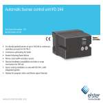
1
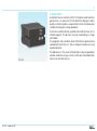
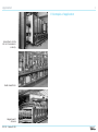
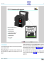
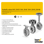
Automatic burner control unit IFD 258 Technical Information · GB 6.1.1.5 Edition 03.08 • For directly ignited burners of unlimited capacity in continuous operation pursuant to EN 746-2 • Continuous self-testing for faults • Immediate fault lock-out or restart following flame failure available as a switchable function • Flame control with UV sensor or ionisation sensor • Diverse installation possibilities via holes or snap mechanism for DIN rail • Space-saving installation on site with IFD 258..I with integrated ignition • Display for program status and flame signal intensity 2 Contents Automatic burner control unit IFD 258 . . . . . . . . . . . . . . . . . 1 Contents . . . . . . . . . . . . . . . . . . . . . . . . . . . . . . . . . . . . . . . . 2 1 Application . . . . . . . . . . . . . . . . . . . . . . . . . . . . . . . . . . . . 4 1.1 Examples of application . . . . . . . . . . . . . . . . . . . . . . . . . 5 1.1.1 Forced draught burners . . . . . . . . . . . . . . . . . . . . . . . . . . . . . 6 1.1.2 Two-stage-controlled burner . . . . . . . . . . . . . . . . . . . . . . . . . 7 1.1.3 Modulating-controlled burner . . . . . . . . . . . . . . . . . . . . . . . . 8 2 Certification . . . . . . . . . . . . . . . . . . . . . . . . . . . . . . . . . . . . 9 3 Function . . . . . . . . . . . . . . . . . . . . . . . . . . . . . . . . . . . . . . 10 3.1 Connection diagrams . . . . . . . . . . . . . . . . . . . . . . . . . . . 10 3.1.1 IFD 258 . . . . . . . . . . . . . . . . . . . . . . . . . . . . . . . . . . . . . . . . . 10 3.1.2 IFD 258..I . . . . . . . . . . . . . . . . . . . . . . . . . . . . . . . . . . . . . . . 12 3.2 Program sequence . . . . . . . . . . . . . . . . . . . . . . . . . . . . 13 3.3 Animation . . . . . . . . . . . . . . . . . . . . . . . . . . . . . . . . . . . . 14 3.4 Program status and fault messages . . . . . . . . . . . . . . 15 3.4.1 Reading off the flame signal . . . . . . . . . . . . . . . . . . . . . . . . 16 4 Parameters . . . . . . . . . . . . . . . . . . . . . . . . . . . . . . . . . . . 17 4.1 Scanning the parameters . . . . . . . . . . . . . . . . . . . . . . . . 17 4.2 Flame control . . . . . . . . . . . . . . . . . . . . . . . . . . . . . . . . . 18 4.2.1 Burner flame signal . . . . . . . . . . . . . . . . . . . . . . . . . . . . . . . 18 4.2.2 Switch-off threshold of the flame amplifier . . . . . . . . . . . . 18 4.3 Behaviour during start-up . . . . . . . . . . . . . . . . . . . . . . . 19 4.3.1 Normal start-up . . . . . . . . . . . . . . . . . . . . . . . . . . . . . . . . . . 19 4.3.2 Start-up without flame signal . . . . . . . . . . . . . . . . . . . . . . . 19 4.3.3 Flame simulation . . . . . . . . . . . . . . . . . . . . . . . . . . . . . . . . 20 4.4 Behaviour during operation . . . . . . . . . . . . . . . . . . . . . 21 4.4.1 Safety time during operation tSB for V1 and V2 . . . . . . . . . 21 4.4.2 Fault lock-out or restart . . . . . . . . . . . . . . . . . . . . . . . . . . . . 21 5 Replacement possibilities . . . . . . . . . . . . . . . . . . . . . . . 23 6 Selection . . . . . . . . . . . . . . . . . . . . . . . . . . . . . . . . . . . . . 24 6.1 Determining the safety time tSA . . . . . . . . . . . . . . . . . . . . . . . . 24 6.1.1 Calculating the safety time tSA . . . . . . . . . . . . . . . . . . . . . . 24 6.2 Selection table . . . . . . . . . . . . . . . . . . . . . . . . . . . . . . . 25 6.2.1 Type code . . . . . . . . . . . . . . . . . . . . . . . . . . . . . . . . . . . . . . . 25 IFD 258 · Edition 03.08 7 Project planning information . . . . . . . . . . . . . . . . . . . . . 26 7.1 Cable selection . . . . . . . . . . . . . . . . . . . . . . . . . . . . . . . 26 7.2 Star electrodes . . . . . . . . . . . . . . . . . . . . . . . . . . . . . . . 26 7.3 Purge . . . . . . . . . . . . . . . . . . . . . . . . . . . . . . . . . . . . . . . 26 7.4 Emergency stop in the event of fire or electric shock . . 27 7.5 Emergency stop triggered by safety interlock . . . . . . . 27 7.6 Overload protection . . . . . . . . . . . . . . . . . . . . . . . . . . . . 27 7.7 Parallel reset . . . . . . . . . . . . . . . . . . . . . . . . . . . . . . . . . . 27 7.8 Remote reset . . . . . . . . . . . . . . . . . . . . . . . . . . . . . . . . . . 27 7.9 Behaviour in the event of flame failure . . . . . . . . . . . . . 27 7.10 Wiring . . . . . . . . . . . . . . . . . . . . . . . . . . . . . . . . . . . . . . 28 7.11 Note on EC type-examination . . . . . . . . . . . . . . . . . . . 28 7.12 Installation of solenoid valves for gas . . . . . . . . . . . . 28 7.13 Flame control . . . . . . . . . . . . . . . . . . . . . . . . . . . . . . . . 28 7.13.1 With ionisation sensor . . . . . . . . . . . . . . . . . . . . . . . . . . . . 28 7.13.2 With UV sensor UVS . . . . . . . . . . . . . . . . . . . . . . . . . . . . . . 28 7.14 Flame signal cut-off point . . . . . . . . . . . . . . . . . . . . . . 28 7.15 Two-stage burner control with two solenoid valves . 29 8 Accessories . . . . . . . . . . . . . . . . . . . . . . . . . . . . . . . . . . 30 8.1 High-voltage cable . . . . . . . . . . . . . . . . . . . . . . . . . . . . 30 8.2 Radio interference suppressed electrode adapters . 30 9 Technical data . . . . . . . . . . . . . . . . . . . . . . . . . . . . . . . . . 31 9.1 Operating controls . . . . . . . . . . . . . . . . . . . . . . . . . . . . 32 9.2 Installation . . . . . . . . . . . . . . . . . . . . . . . . . . . . . . . . . . 32 10 Maintenance cycles . . . . . . . . . . . . . . . . . . . . . . . . . . . 33 11 Legend . . . . . . . . . . . . . . . . . . . . . . . . . . . . . . . . . . . . . . 33 Contents 12 Glossary . . . . . . . . . . . . . . . . . . . . . . . . . . . . . . . . . . . . 34 12.1 Waiting time tW . . . . . . . . . . . . . . . . . . . . . . . . . . . . . . 34 12.2 Safety time on start-up tSA . . . . . . . . . . . . . . . . . . . . . 34 12.3 Ignition time tZ . . . . . . . . . . . . . . . . . . . . . . . . . . . . . . 34 12.4 Flame simulation/Flame simulation delay time tLV . 34 12.5 Safety time during operation tSB . . . . . . . . . . . . . . . 35 12.6 Flame signal . . . . . . . . . . . . . . . . . . . . . . . . . . . . . . . . 35 12.7 Flame detector . . . . . . . . . . . . . . . . . . . . . . . . . . . . . . 35 12.8 Fault lock-out . . . . . . . . . . . . . . . . . . . . . . . . . . . . . . . . 35 12.9 Safety interlocks (Limits) . . . . . . . . . . . . . . . . . . . . . . . 35 12.10 Gas valve V1 . . . . . . . . . . . . . . . . . . . . . . . . . . . . . . . . 35 12.11 Continuous operation . . . . . . . . . . . . . . . . . . . . . . . . 35 Feedback . . . . . . . . . . . . . . . . . . . . . . . . . . . . . . . . . . . . . . 36 Contact . . . . . . . . . . . . . . . . . . . . . . . . . . . . . . . . . . . . . . . 36 IFD 258 · Edition 03.08 3 4 1 Application IFD 258 IFD 258 · Edition 03.08 Automatic burner control unit IFD 258 ignites and monitors gas burners. As a result of its fully electronic design it reacts quickly to various process requirements and is therefore also suitable for frequent cycling operation. It can be used for directly ignited industrial burners of unlimited capacity. The burners may be modulating or stagecontrolled. The program status and the level of the flame signal can be read directly from the unit. The cut-off point can be set using a potentiometer. The behaviour in the event of flame failure during operation can be selected using a switch. Either an immediate fault lock-out or a restart occurs. Application 5 1.1 Examples of application Intermittent shuttle kiln in the ceramics industry Roller hearth kiln Bogie hearth furnace IFD 258 · Edition 03.08 Application > Examples of application 6 1.1.1 Forced draught burners Control: ON/OFF Gas valve and air valve are activated simultaneously. The burner is ignited and monitored by a single electrode. In the event of a flame failure, an immediate fault lock-out occurs. L1, N, PE PLC 4 3 IFD 258 µC 8 9 13 14 11 VAS..L VR..R IFD 258 · Edition 03.08 10 5 ZMI Application > Examples of application 7 1.1.2 Two-stage-controlled burner Control: ON/OFF or ON/HIGH/LOW/OFF The burner BIO/BIC starts at low-fire rate. Once the normal operating state is reached, the automatic burner control unit for continuous operation IFD 258 will release control. The PLC can now pulse the air solenoid valve VR..R in order to control the capacity between high and low fire. L1, N, PE PLC 4 3 IFD 258 µC 8 9 13 14 10 11 5 GIK..B VAS VR..R IFD 258 · Edition 03.08 BIO/ BIC Application > Examples of application 8 1.1.3 Modulating-controlled burner Control: ON/OFF/continuous The PLC uses the actuator IC 20 to move the air butterfly valve BVA to ignition position. The burner BIO/BIC starts at low-fire rate. Once the normal operating state is reached, the PLC uses the actuator IC 20 and the air butterfly valve BVA to control the burner capacity. . L1, N, PE mA 4 PLC 3 IFD 258 µC 8 9 13 14 11 10 5 VAS GIK IC 20 M BVA IFD 258 · Edition 03.08 BIO/ BIC 9 2 Certification The IFD 258 complies with the requirements of the following directives and standards: – Machinery Directive (2006/42/EC) – EN 298 – Low Voltage Directive (2006/95/EC) – Electromagnetic Compatibility Directive (2004/108/EC) Certification pursuant to – Gas Appliances Directive – FM is currently being prepared. IFD 258 · Edition 03.08 10 3 Function IFD 258 3.1 Connection diagrams s1 For the explanation of symbols, see Legend. For cable selection and wiring, see Project planning information. 230V F1 s2 v1 c v2 3.1.1 IFD 258 Ionisation control in double-electrode operation 1 2 3 4 5 6 7 8 9 10 11 12 13 14 max. 2 A, 253 V~ max. 2 A, 253 V~ Z * I L1 (L1) N (L2) PE Ionisation control in single-electrode operation IFD 258 t s1 230V F1 s2 c v1 v2 1 2 3 4 5 6 7 8 9 10 11 12 13 14 max. 2 A, 253 V~ max. 2 A, 253 V~ * L1 (L1) N (L2) PE IFD 258 · Edition 03.08 Function > Connection diagrams > IFD 258 11 UV control In the case of UV control, only intermittent operation is possible. IFD 258 s1 230V F1 s2 c v1 v2 1 2 3 4 5 6 7 8 9 10 11 12 13 14 1 UVS 2 3 max. 2 A, 253 V~ max. 2 A, 253 V~ * L1 (L1) N (L2) PE IFD 258 · Edition 03.08 Function > Connection diagrams 12 3.1.2 IFD 258..I The IFD 258..I is suitable for double-electrode operation and for UV control. Single-electrode operation is not possible. IFD 258..I s1 c Ionisation control in double-electrode operation 230V F1 s2 v1 v2 1 2 3 4 5 6 7 8 9 10 11 12 13 14 max. 2 A, 253 V~ Z max. 2 A, 253 V~ * I L1 (L1) N (L2) PE UV control In the case of UV control, only intermittent operation is possible. IFD 258..I s1 c 230V F1 s2 v1 v2 1 2 3 4 5 6 7 8 9 10 11 12 13 14 1 UVS 2 3 max. 2 A, 253 V~ max. 2 A, 253 V~ * L1 (L1) N (L2) PE IFD 258 · Edition 03.08 Function 13 Connect voltage In the event of fault signal: reset 00 Safety interlocks (Li) Start-up position/standby 01 Waiting time tW running, start-up with * signal Flame simulation check 02 Safety time on start-up tSA running, gas valve opens, ignition in process No flame detected: fault lock-out 04 Flame detected: Operation signalling contact closes Flame fails: Safety time during operation tSB starts to elapse, restart or fault lock-out 04 Normal shut-down via * signal 00 Operation signalling contact opens, gas valve closes IFD 258 · Edition 03.08 3.2 Program sequence Normal start-up If, after applying voltage, an “old” fault is still being signalled, it will be necessary to reset this first. The safety interlocks are closed, the IFD reverts to start-up position/standby and conducts a self-test. If it does not determine a malfunction of the internal electronic circuitry or of the flame sensor, the flame simulation check then commences. This takes place in start-up position during the waiting time tW. If no flame simulation is detected during that period, the safety time on start-up tSA then starts to elapse. Voltage is supplied to the gas valve and ignition transformer. The burner starts. After the safety time on start-up tSA has elapsed, the operation signalling contact closes. This completes start-up. Start-up without flame signal If, after the gas valve has opened and the ignition has been activated, no flame is detected during the safety time on startup tSA, a fault lock-out will then occur. Behaviour in the event of flame failure during operation If the flame fails during operation, the IFD 258 will perform a fault lock-out within the safety time during operation t SB. Depending on the setting of the program selector switch, the valves will be closed immediately or the burner will be restarted once. If the burner does not function, a fault lock-out occurs. Function 3.3 Animation The interactive animation shows the function of the automatic burner control unit IFD. Click on the picture. The animation can be controlled using the control bar at the bottom of the window (as on a DVD player). IFD 258 · Edition 03.08 14 To play the animation, you will need Adobe Reader 6 or a newer version. If you do not have Adobe Reader on your system, you can download it from the Internet. Go to www.adobe.com, click on “Get Adobe Reader” and follow the instructions. If the animation does not start to play, you can download it from the document library (Docuthek) as an independent application. Function 15 3.4 Program status and fault messages Operating controls A: 2-digit 7-segment display for indicating program status and flame signal. B: Reset/Information button to reset the system after a fault or to call up the flame signal on the display. C:Mains On/Off button. A C B The 7-segment display (A) shows the program status. In the event of a fault, the IFD halts the program run and the display starts to blink. The program status and cause of the fault are displayed in coded form. Program status Unit is switched off IFD 258 · Edition 03.08 DISPLAY –– Fault message (blinking) Start-up position/standby 00 Waiting time/Pause time 01 Flame simulation Safety time on start-up tSA 02 Start-up without flame signal Operation 04 Flame failure during operation 09 Oscillating thermostat signal 10 Too many remote resets 52 Permanent remote reset 53 Time between two start-ups is too short Function > Program status and fault messages 3.4.1 Reading off the flame signal Internally: The flame signal can be called up on the display by pressing (> 2 seconds) the Reset/Information button. The flame signal of the burner is indicated in µA. A value between 0 and 25 µA is displayed. Important! When using an external µ-ammeter, you must make sure that this µ-ammeter cannot trigger an incorrect flame signal. IFD 258 · Edition 03.08 16 17 4 Parameters Description Burner flame signal Burner switch-off threshold Burner restart Safety time during operation for V1 and V2 tSB Burner safety time on start-up tSA Last fault Second to last occurring fault Third to last occurring fault Tenth to last occurring fault Parameter 01 04 12 14 22 81 82 83 … 90 1) Via potentiometer in lower section of housing. 2) Via switch in lower section of housing. 3) Quote in your order. On parameterisation, ensure that the program sequence matches the application. Select the parameters so that the burner can be operated as intended in all operating phases. 4.1 Scanning the parameters During operation, the 7-segment display shows the program status. The flame signal and all following parameters of the IFD can be scanned one after the other by repeatedly pressing the Reset/Information button (for 2 s). In the event of a fault, the IFD halts the program run, the display blinks and it then displays the cause of the fault in coded form. IFD 258 · Edition 03.08 Value range Factory default settings 0 – 25 μA 2 – 20 µA 2 µA 0; 1 0 1; 2 s 3) 3; 5; 10 s 3) Adjustable* 1) 2) Parameters 4.2 Flame control 4.2.1 Burner flame signal Parameter 01 Flame signal of the burner, display in µA, measuring range: 0 – 30 µA. 4.2.2 Switch-off threshold of the flame amplifier Parameter 04 The sensitivity at which the burner control unit still detects a flame can be set between 2 and 20 µA. Example: In the case of UV control with the UV sensor UVS, the signal of the burner to be monitored is influenced by other burners. The set value can be increased via a potentiometer in the lower section of the housing so that only the flame of the system’s “own” burner is detected. The measured flame signal of the system’s “own” burner should be at least 3 µA (empirical value) higher than the set switchoff threshold. IFD 258 · Edition 03.08 18 Parameters 19 4.3 Behaviour during start-up 4.3.2 Start-up without flame signal 4.3.1 Normal start-up The safety time tSA can be read on the type label (parameter 22). 01 02 tW tZ 04 1 3 10 11 5 13-14 8-9 88 L1 * tW tZ 02 1 3 10 11 5 13–14 8–9 88 L1 ϑ t tSA t tSA Once the start-up signal (J) has been applied, the automatic burner control unit checks the burner for flame simulation during the waiting time tW. If no flame simulation is detected during that period, the safety time on start-up tSA (3, 5 or 10 s) then starts to elapse. This forms the minimum operating time of the automatic burner control unit and the burner. Voltage is supplied to the gas valve and ignition transformer. After the safety time on start-up tSA has elapsed and the flame signal has been received, the operation signalling contact between terminals 13 and 14 closes. The display indicates the current program status 04 . IFD 258 · Edition 03.08 01 02 If, after a successful burner start, the automatic burner control unit does not detect a flame signal during the safety period on start-up tSA, a fault lock-out will occur (fault signalling contact between terminals 8 and 9 closes). During the entire safety time on start-up tSA, the gas valve V1 is open. The display blinks and indicates 02 . Parameters > Behaviour during start-up 20 4.3.3 Flame simulation 00 01 02 . . . 88 V1 t tW The flame simulation check is conducted after applying the start-up signal 00 (J) during the waiting time 02 . . . tW.88 01 tW 01 tLV V1 1 3 10 11 5 13–14 8–9 L1 ϑ t t If flame simulation is signalled during start-up, the flame simulation delay time tLV starts to elapse. If the flame simulation is discontinued during the flame simulation delay time tLV (max. 15 s), the burner will start up. Otherwise, a fault lock-out occurs. The display blinks and indicates 01 . IFD 258 · Edition 03.08 Start-up signal, safety interlock The start-up signal is the same as the signal in the safety interlock. If the start-up/safety interlock signal drops more than three times in succession during start-up, an inadmissible quantity of non-combusted gas can reach the combustion chamber during the safety time via open gas valves. Therefore, a fault lock-out is performed on the automatic burner control unit IFD 258 following three consecutive drops of the start-up/ safety interlock signal (blinking 09 ). Parameters 4.4 Behaviour during operation 4.4.1 Safety time during operation tSB for V1 and V2 Parameter 14 This indicates the safety time during operation tSB for valves V1 and V2. The default in accordance with EN 298 is 1 s. The IFD is also available with a safety time during operation tSB of 2 s. Prolonging the time increases the installation availability in the case of brief-duration signal fades (e.g. fades of the flame signal). In accordance with EN 746-2, the safety time of the installation during operation (including closing time of the valves) may not exceed 3 seconds (note the requirements of the Standards). 21 4.4.2 Fault lock-out or restart Parameter 12 A switch in the lower section of the housing determines whether the IFD starts a one-off restart or performs an immediate fault lock-out for the burner after a flame failure (see also Project planning information). Immediate fault lock-out following flame failure Parameter 12 = 0, Switch in fault lock-out position : 04 <2 s 04 tSB 1 3 10 11 5 13–14 8–9 88 L1 ϑ t After a flame failure during operation, the IFD 258 will perform a fault lock-out within the safety time during operation tSB (the safety time during operation tSB is 1 second. The IFD 258 is available with a safety time of 2 seconds upon request). At the same time, the gas valve is closed. The fault signalling contact closes and the display blinks and indicates 04 – see table “Program status and fault messages”. After a fault lock-out, the IFD 258 can be reset, either by using the button on the front panel or an external button. Several automatic burner control units can be reset in parallel using the external button. The IFD 258 cannot be reset by mains failure. The fault signalling contact does, however, open as soon as the mains voltage fails. t IFD 258 · Edition 03.08 Parameters > Behaviour during operation 22 Restart following flame failure Parameter 12 = 1, Switch in restart position : 1x 04 01 02 >2 s tSB tW tZ tSA 04 1 3 10 11 5 13–14 8–9 88 L1 ϑ t If the IFD detects a flame failure after a minimum operating time of 2 s, the valves are closed and the operation signalling contact (terminals 13 and 14) is opened within time tSB. The automatic burner control unit now attempts to restart the burner once. If the burner does not function, a fault lock-out occurs. The display blinks and indicates 02 . If, on restart, the automatic burner control unit detects a flame signal within the safety time on start-up t SA, the operation signalling contact closes. The display indicates the current program status 04 . In accordance with EN 746-2, a restart may be conducted only if the safety of the installation is not impaired. Restart is recommended for burners which occasionally display unstable behaviour during operation. The precondition for a restart is that activation of the restart allows the burner to restart as intended (in all operating phases). It must be ensured in this case that the program sequence started by the IFD matches the application. IFD 258 · Edition 03.08 23 5 Replacement possibilities The new automatic burner control unit IFD 258 is interchangeable with the IFS 258 and provides almost all of the previous functions of the IFS 258. The housing dimensions and hole pattern are unchanged. The new upper section of the housing will fit on the existing lower section (for further information see operating instructions “Automatic burner control unit for continuous operation IFD 258”). IFS 258 up to construction stage B D-49018 Osnabrück, Germany D-49018 Osnabrück, Germany IFS 258 CE-0063AT1088 IFD 258 as of construction stage A IFD 258 230 VAC 50/60 Hz -20/+60 °C ts IP 40 (30) CE-0063BXXXXX 230 VAC 50/60 Hz -20/+60 °C -4/+140 °F ts 5/1s IP 54/NEMA 3 Signalling contact for fault and operating signals Flame signal called up via test jacks in upper section of housing using external measuring instrument Complies with requirements in accordance with EN 1993 Fault signal with no mains voltage supplied Signalling contact for fault and operating signals Flame simulation indicated by yellow LED Flame simulation indicated on 7-segment display = 01 Operation indicated by yellow and green LEDs Mains voltage = 100, 115, 200, 230 V Operation indicated on 7-segment display = 04 Mains voltage = 100, 120, 200, 230 V No protection against frequent remote resets Protection against frequent remote resets (blinking 10 ) No protection against frequent switch-off during tSA Protection against frequent switch-off during tSA (blinking 09 ) IFD 258 · Edition 03.08 The flame signal can be called up on the 2-digit 7-segment display. Complies with requirements in accordance with EN 2003 Fault signal with mains voltage supplied 24 6 Selection 6.1 Determining the safety time tSA The safety time on start-up tSA = 3 s, 5 s or 10 s should be indicated when ordering. The details are based on the 1997 edition of EN 746-2. EN 746-2 PN tSA ½ 70 kW 5s > 70 kW* 3s ½ 350 kW 10 s > 350 kW** 5s 0 ∞* 10 s * PZ 0,1 × PN, PZmax = 350 kW ** PZ 0,33 × PN, PZmax = 350 kW PN = rated capacity PZ = Pilot burner capacity (this is defined via the gas valve V1) The safety time on start-up tSA depends on the burner type, the burner capacity and the respective application. IFD 258 · Edition 03.08 6.1.1 Calculating the safety time tSA Burner with mechanical combustion air supply Natural draught burner with direct ignition Natural draught burner with pilot burner Burner capacity Safety time on start-up tSA 1.00 kW 5s Ignition burner input rating at a level of 10 % of nominal heat input with a maximum of 350 kW. Selection 25 6.2 Selection table IFD 2 ● 5 ● 8 ● -3 -5 -10 /1 ● ● ● ● * Only available for IFD 258..Q and IFD 258..W. = standard, = available Order example IFD 258-5/1W 6.2.1 Type code /2 ● Y ● Q ● P ● W ● I* Code IFS 2 5 8 -3 -5 -10 /1 /2 W R Y P I* Description Automatic burner control unit Series 200 With ionisation or UV control Immediate fault lock-out or restart, switchable Safety time on start-up tSA: 3 s 5s 10 s Safety time during operation tSB: 1 s 2s Mains voltage: 230 V~, 50/60 Hz 115 V~, 50/60 Hz 200 V~, 50/60 Hz 100 V~, 50/60 Hz Integrated electronic ignition * if “none”, this specification is omitted. IFD 258 · Edition 03.08 26 7 Project planning information 7.1 Cable selection Use mains cable suitable for the type of operation and complying with local regulations. Signal and control line: max. 2.5 mm2. Cable for burner earth/PE wire: 4 mm2. Do not route IFD cables in the same cable duct as frequency converter cables or other cables emitting strong fields. Ionisation cable and ignition cable Use unscreened high-voltage cable for both lines (see “Accessories”). Recommended cable length: Ionisation cable – max. 75 m, Ignition cable: IFD 258: max. 5 m, recommended < 1 m (with TZI/TGI), IFD 258..I: max. 1 m, recommended < 0.7 m. The longer the ignition cable, the lower the ignition capacity. Avoid external electrical interference. Lay cables individually and not in a metal conduit, if possible. Lay the ignition cable and UV cable/ionisation cable as far apart as possible. Screw the ignition cable securely into the ignition transformer TGI/TZI and feed it out of the unit on the shortest possible route (no loops). Only use radio interference suppressed electrode adapters (with 1 kΩ resistor) for ignition electrodes, see “Accessories”. IFD 258 · Edition 03.08 UV cable The UV cable should be no longer than 100 m and should be laid as far as possible from the ignition cable. 7.2 Star electrodes We recommend using 7.5 kV ignition transformers on burners with star electrodes. 7.3 Purge L1, N, PE In the case of multiple burner applications, burners with forced air supply are used. The air for combustion and pre-purge is supplied by a central SPS fan controlled by a separate logic. This logic determines the purging time and controls an external relay that switches the air valve to purge. The automatic burner control unit must not be activated during 4 3 IFS 258 the safety interlock, purging. This is achieved by interrupting 8 9 amongst other methods.µC 13 14 11 10 5 GIK..B VAS VR..R Purge BIO/ BIC N Project planning information 27 7.4 Emergency stop in the event of fire or electric shock If there is a risk of fire, electric shock or similar, inputs L1, N and 3 (start-up/safety interlock signal) of the IFD should be disconnected from the electrical power supply. Important! This should be reflected in the wiring on site! 7.5 Emergency stop triggered by safety interlock The safety interlock turns off the power to the input 3 (start-up/ safety interlock signal), such as in the event of air deficiency or similar. 7.6 Overload protection To protect the unit against overload by frequent cycling, only a specific number of start-up attempts can be carried out by the IFD. The maximum number of start-up attempts per minute depends on the safety time tSA and the ignition unit. tSA [s] 3 5 10 3 5 10 tZ [s] 1,8 3 6 1,8 3 6 Type of ignition External TZI External TZI External TZI IFD..I IFD..I IFD..I Cycle lock [s] 10 12 15 36 60 120 If too many start-up attempts are made, 53 flashes on the display to indicate a fault. 7.7 Parallel reset Several automatic burner control units can be reset in parallel using the external button. The IFD 258 cannot be reset by mains failure. The fault signalling contact does, however, open as soon as the mains voltage fails. IFD 258 · Edition 03.08 7.8 Remote reset Permanent The unit can no longer be reset by permanent remote reset: If a remote reset signal is permanently applied to terminal 4, 52 flashes on the display as a warning signal. The IFD continues operation until it locks off. Automatic (PLC) Check whether automatic remote reset (PLC) complies with standards (reset for no longer than 1 second). If a fault is acknowledged by remote reset too often, 10 flashes on the display to indicate a fault (too many remote resets). The error can only be acknowledged with the Reset/Information button on the unit. The burner malfunction must be remedied. The malfunction can not be remedied by changing the method of activation. 7.9 Behaviour in the event of flame failure In the event of a flame failure, either a restart or an immediate fault lock-out can be selected using a switch in the upper section of the automatic burner control unit IFD 258. Restart Select for burners that occasionally demonstrate unstable flame behaviour. Immediate fault lock-out Select an immediate fault lock-out when using the unit with slow-closing air control valves or continuous control, if the burner may not be started at maximum capacity, for burners with a capacity of over 120 kW in accordance with EN 676 and in the case of On/Off intermittent operation. Project planning information 28 7.10 Wiring 7.13 Flame control The IFD is suitable for hard wiring only. Do not reverse phase and neutral conductor. Different phases of a three-phase current system must not be installed at the IFD. No voltage may be connected to the valve and ignition outputs. Do not use unused terminals as support terminals. The signalling contacts for operating and fault signals do not meet the requirements for safety extra low voltage (SELV/ PELV). The burner should be adequately earthed. Incorrect wiring and an insufficient earth connection can cause damage to the equipment during single-electrode operation. In the case of single-electrode operation, only ignition transformers of type TZI or TGI may be used. The use of pulse-spark or high-frequency ignition devices is not permitted. 7.13.1 With ionisation sensor The IFD generates an alternating voltage (230 V AC) between the sensing electrode and burner earth. The flame rectifies this voltage. Only the DC signal (> 2 µA) is recognised by the automatic burner control unit as a flame. A flame cannot be simulated by a short-circuit. Ignition and monitoring with a single electrode are possible (see connection diagram). 7.11 Note on EC type-examination Since EN 298 (1993) does not describe all functions of the IFD, the operator is responsible for ensuring that all parameters and functions are matched to the respective application. 7.12 Installation of solenoid valves for gas During the safety time on start-up tSA, the burner must be supplied with gas and ignited. For this reason, the gas solenoid valve should be installed as close as possible to the burner itself. IFD 258 · Edition 03.08 7.13.2 With UV sensor UVS A UV tube inside the UV sensor detects the ultraviolet light of a flame. It does not respond to sunlight, incandescent bulb light or infrared radiation emitted by hot workpieces or redhot furnace walls. In the event of incident UV radiation the UV sensor rectifies the supplied alternating voltage. As with ionisation control, the automatic burner control unit only detects this DC signal. In the case of flame control with the UV sensor UVS, only intermittent operation is allowed (a flame simulation check must be carried out once every 24 hours). 7.14 Flame signal cut-off point The cut-off point can be set between 2 and 20 µA using a potentiometer in the upper section of the housing. The automatic burner control unit IFD is set to 2 µA at the factory. If a flame is detected during the burner start, 01 flashes on the display to indicate a fault. Project planning information 29 safety time tSA has elapsed, the operation signalling contact closes and valve V2 is opened. The IFD is equipped with two signallings1contacts for operating and fault signals. For controlling two-stage burners, a bridge F1 in the lower section of the housing between must be installed terminals 12 and 13. Valve V2 is connected to terminal 14. Example of application Control: ON/OFF or ON/HIGH/LOW/OFF The burner BIO/BIC starts at low-fire rate. Once the normal operating state is reached, the automatic burner control unit IFD 258 opens the air valve. The burner switches to high-fire operation. 230V 7.15 Two-stage IFD 258 burner control with two solenoid valves s2 c v1 v2 1 2 3 4 5 6 7 8 9 10 11 12 13 14 max. 2 A, 253 V~ Z I max. 2 A, 253 V~ IFD 258 * µC 8 9 13 14 L1 (L1) N (L2) PE 12 11 10 5 GIK..B Program sequence 01 02 tW tZ VAS 04 1 3 10 11 5 14 8-9 VR..R 88 L1 ϑ V1 V2 t tSA During the waiting time tW after heat demand, checks are made for flame simulation and faults. If no flame simulation is detected, the IFD 258 opens the gas valve V1 and ignites the burner. The ignition time tZ is constant. The safety time tSA starts with the ignition time tZ. If a flame is detected during the safety time, the fault signalling contact closes. Once the IFD 258 · Edition 03.08 BIO/ BIC 30 8 Accessories 8.1 High-voltage cable FZLSi 1/7 -50°C (-58°F) to 180°C (356°F), Order No.: 04250410, FZLK 1/7 -5°C (23°F) to 80°C (176°F), Order No.: 04250409. 8.2 Radio interference suppressed electrode adapters Plug cap, 4 mm (0.16 inch), interference-suppressed, Order No. 04115308. Straight adapter, 4 mm (0.16 inch), interference-suppressed, Order No. 04115307. Straight adapter, 6 mm (0.2 inch), interference-suppressed, Order No. 04115306. IFD 258 · Edition 03.08 31 9 Technical data Mains voltage for grounded and ungrounded mains: 200 V AC, -15/+10%, 50/60 Hz, 120 V AC, -15/+10%, 50/60 Hz, 100 V AC, -15/+10%, 50/60 Hz, 230 V AC, -15/+10%, 50/60 Hz. Safety time on start-up tSA: 3, 5 or 10 s. Safety time during operation tSB: < 1 s, < 2 s. Ignition time tZ: approx. 2, 3 or 6 s. Power consumption: IFD 258: approx. 9 VA, IFD 258..I: approx. 9 VA + 25 VA during ignition. Output voltage for valves and ignition transformer = mains voltage. Contact rating: Ignition output: max. 2 A, cos j = 0.2, Valve output: max. 1 A, cosj = 1, Signalling contacts: max. 2 A, 253 V AC, Max. number of operating cycles: 250,000. Max. number of operating cycles: Reset button: 1000, Mains button: 1000. Signal inputs: Input voltage Signal “1” Signal “0” Frequenz 110/120 V AC 220/240 V AC 80 – 126.5 V 160 – 253 V 0 – 20 V 0 – 40 V 50/60 Hz Input current signal inputs: Signal “1”: typ. 2 mA. IFD 258 · Edition 03.08 Flame control: Sensor voltage: approx. 230 V AC, Sensor current: > 1 µA, Max. sensor current: ionisation < 28 µA. Ignition cable: IFD 258: max. 5 m, recommended < 1 m (with TZI/TGI), IFD 258..I: max. 1 m, recommended < 0.7 m. Permissible UV sensors: Elster Kromschröder models UVS 1, 5 and 6 for ambient temperatures from -40 to +80°C (-40 to 176°F). Valve connections: 1. IFD 258..I: Ignition voltage: 22 kVpp, Ignition current: 25 mA, Spark gap: 2 mm, max. 5 mm. Fuse in unit: F1: T 3.15A H 250 V pursuant to IEC 127-2/5. Ambient temperature: -20 to +60°C (-4 to +140°F). Relative humidity: no condensation permitted. Enclosure: IP 54 pursuant to IEC 529. Overvoltage category III pursuant to EN 60730. Cable gland: M16. Installation position: any. Weight: IFD 258: 610 g, IFD 258..I: 770 g. Technical data 32 9.1 Operating controls 112,8 ) (4.44" 75,5 (2.97") A C B 35 (1.3 8" ) 85, (3.3 5 6") 70 ") (2 .75 9.2 Installation M5 M5 35 IFD 258 · Edition 03.08 (1.38") M16 A: 2-digit 7-segment display to display program status and flame signal. B: Reset/Information button to reset the system after a fault or to call up the flame signal on the display. C: Mains On/Off button. The unit can be installed in any position. The installation position should however be selected carefully in order to ensure that the display can easily be read. The housing is made of impact-resistant plastic. The upper section containing the detection circuitry is a push connection fit into the lower section. The connection terminals, earthing strip and neutral bus are located in the lower section. The upper section of the housing is attached to the lower section using two screws. The lower section can either be snapped onto a DIN rail or secured with two M5 screws. In order to obtain enclosure IP 54, two sealing washers must be placed beneath the M5 screws. The housing has 6 knock-out holes for M16 plastic screw connectors. . 33 10 Maintenance cycles The automatic burner control unit IFD 258 requires little servicing. 11 Legend Symbol Description 88 Affichage 88 Affichage clignotant Chaîne de sécurité Signal de démarrage Transformateur d’allumage Vanne gaz Signal de flamme Indication de service / RUN Indication de défaut Réarmement / info Signal d’entrée Signal de sortie Z I Allumage / haute tension Ionisation Entrée / sortie circuit de sécurité IFD 258 · Edition 03.08 tW Temps d’attente tLV Temps de temporisation de flamme parasite tZ Temps d’allumage tSA Temps de sécurité au démarrage 3, 5 ou 10 s tSB Temps de sécurité en service < 1 s ou < 2 s 34 12 Glossary 12.3 Ignition time tZ 12.1 Waiting time tW If no malfunction is detected during the waiting time tW, the ignition time tZ then starts to elapse. Voltage is supplied to the gas valve V1 and the ignition transformer and the burner is ignited. The duration of the ignition time is either 2, 3 or 6 seconds (see Technical data). 01 02 tW 02 1 3 10 11 5 13–14 8–9 88 L1 ϑ 04 01 02 tZ 1 3 10 11 5 13-14 8-9 t tSA Once the start-up signal J has been applied, the waiting time tW starts to elapse. During this time, a self-test is conducted to detect errors in internal and external circuit components. If no malfunction is detected, the burner will start up. 12.2 Safety time on start-up tSA 01 02 tW tZ 04 12.4 Flame simulation/Flame simulation delay time tLV 01 L1 * tW t This refers to the period of time between switching on and switching off of the gas valve V1, when no flame signal is detected. The safety time on start-up tSA (3, 5 or 10 s) is the minimum operating time of the burner and automatic burner control unit. t tSA 01 1 3 10 11 5 13-14 8-9 L1 * tZ 88 tSA IFD 258 · Edition 03.08 tW 88 tLV 1 3 10 11 5 13–14 8–9 L1 ϑ t Flame simulation is an incorrect flame signal. If flame simulation is detected during start-up, the flame simulation delay time tLV (max. 25 s) starts to elapse. If the flame simulation is discontinued during the flame simulation delay time tLV, startup can be initiated or operation continued. Otherwise, a fault lock-out occurs. Glossary 35 12.5 Safety time during operation tSB 04 04 tSB 1 3 10 11 5 13–14 8–9 12.9 Safety interlocks (Limits) The limiters in the safety interlock (linking of all the relevant safety control and switching equipment for the use of the application, for example STB (safety temperature limiter), Gasmin, Gasmax ...) must isolate input 3 from the voltage supply. 88 L1 ϑ 12.10 Gas valve V1 t If the flame fails during operation, the valves are closed within the safety time tSB. The default safety time during operation tSB in accordance with EN 298 is 1 second. In accordance with EN 746-2, the safety time of the installation during operation (including closing time of the valves) may not exceed 3 seconds (see Project planning information). Note the requirements of the Standards! 12.6 Flame signal If a flame is detected, the flame detector will supply a flame signal. 12.7 Flame detector The flame detector detects and signals the presence of a flame. The flame detector usually consists of a flame sensor, an amplifier and a relay to produce the signal. These components, with the exception of the flame sensor itself, are accommodated within a single housing (IFW 50). 12.8 Fault lock-out In the event of a fault lock-out, all valves are closed and a fault signalled. Resetting must take place manually following a fault lock-out. IFD 258 · Edition 03.08 The gas valve V1 is opened at the start of the safety time on start-up tSA. It remains open in the event of a fault, or until the burner is switched off. 12.11 Continuous operation The gas burner has been running for longer than 24 hours and was not switched off during that time. 36 Feedback Finally, we are offering you the opportunity to assess this “Technical Information (TI)” and to give us your opinion, so that we can improve our documents further and suit them to your needs. Clarity Found information quickly Searched for a long time Didn’t find information What is missing? No answer Comprehension Coherent Too complicated No answer Scope Too little Sufficient Too wide No answer Use To get to know the product To choose a product Planning To look for information Navigation I can find my way around I got “lost” No answer My scope of functions Technical department Sales No answer Remarks Kromschröder AG Michael Rehkamp [email protected] Osnabrück (Adobe Reader 7 or higher required) Elster Kromschröder GmbH Postfach 2809 · 49018 Osnabrück Strotheweg 1 · 49504 Lotte (Büren) Germany T +49 541 1214-0 F +49 541 1214-370 [email protected] www.kromschroeder.com www.elster.com IFD 258 · Edition 03.08 The current addresses of our international agents are available on the Internet: www.kromschroeder.com Sales Kromschröder, a product brand of the Elster Group We reserve the right to make technical modifications in the interests of progress. Copyright © 2007 Elster Group All rights reserved. 03250724 1Contact