1
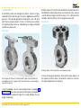
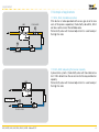
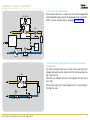
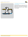
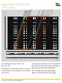
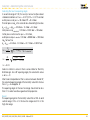
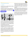
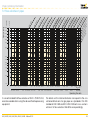
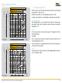
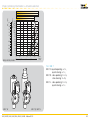
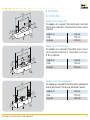
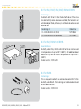
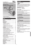
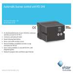
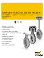
Butterfly valves BVG, BVGF, BVA, BVAF, BVH, BVHS, BVHM Technical Information · GB 3 Edition 09.12 • • • • • • • • • • • For gas, air, hot air and flue gas Low leakage rate and pressure loss High control accuracy BVG and BVA with reduced nominal diameters Butterfly valve can be mounted directly onto the actuator IC 20 or IC 40 Suitable for intermittent operation BVGF, BVAF work clearance-free Low-maintenance operation EC type-tested and certified BVHM: FM approved BVG: certified pursuant to GOST-TR Contents Butterfly valves BVG, BVGF, BVA, BVAF, BVH, BVHS, BVHM . 1 Contents . . . . . . . . . . . . . . . . . . . . . . . . . . . . . . . . . . . . . . . . 2 1 Application . . . . . . . . . . . . . . . . . . . . . . . . . . . . . . . . . . . . . 3 1.1 Example of applications . . . . . . . . . . . . . . . . . . . . . . . . . 6 1.1.1 BVG, BVGF, lambda correction . . . . . . . . . . . . . . . . . . . . . . . 6 1.1.2 BVA, BVAF, adjusting the burner capacity . . . . . . . . . . . . . . 6 1.1.3 BVH, hot air compensation . . . . . . . . . . . . . . . . . . . . . . . . . . 7 1.1.4 BVHS, safety closing function in the event of a mains voltage failure . . . . . . . . . . . . . . . . . . . . . . . . . . . . . . . . . . . . . . . . . 7 1.1.5 BVHM, large number of operating cycles for intermittent operation . . . . . . . . . . . . . . . . . . . . . . . . . . . . . . . . . . . . . . . . . . . . 8 2 Certification . . . . . . . . . . . . . . . . . . . . . . . . . . . . . . . . . . . . 9 3 Function . . . . . . . . . . . . . . . . . . . . . . . . . . . . . . . . . . . . . . 10 4 Replacement possibilities for butterfly valves . . . . . . . . . 11 4.1 DKG is to be replaced by BVG . . . . . . . . . . . . . . . . . . . . 11 4.2 DKL is to be replaced by BVA . . . . . . . . . . . . . . . . . . . . 12 4.3 K is to be replaced by BVHM . . . . . . . . . . . . . . . . . . . . 13 4.4 K is to be replaced by BVHS . . . . . . . . . . . . . . . . . . . . . 14 4.5 DKR is to be replaced by BVH . . . . . . . . . . . . . . . . . . . . 15 5 Flow rate . . . . . . . . . . . . . . . . . . . . . . . . . . . . . . . . . . . . . 16 5.1 Flow rate curves for BVG, BVGF, BVA, BVAF . . . . . . . . . 16 5.1.1 With full bore = nominal diameter . . . . . . . . . . . . . . . . . . . 16 5.1.2 With 1 x reduced bore . . . . . . . . . . . . . . . . . . . . . . . . . . . . . 17 5.1.3 With 2 × reduced bore . . . . . . . . . . . . . . . . . . . . . . . . . . . . 18 5.1.4 kV values . . . . . . . . . . . . . . . . . . . . . . . . . . . . . . . . . . . . . . . 19 5.2 Flow rate curves for BVH, BVHM, BVHS . . . . . . . . . . . 20 5.2.1 kV values . . . . . . . . . . . . . . . . . . . . . . . . . . . . . . . . . . . . . . . 21 6 Selection . . . . . . . . . . . . . . . . . . . . . . . . . . . . . . . . . . . . . 22 6.1 Type code . . . . . . . . . . . . . . . . . . . . . . . . . . . . . . . . . . . 22 6.2 Determining the nominal size . . . . . . . . . . . . . . . . . . . 23 6.2.1 Calculating the nominal size . . . . . . . . . . . . . . . . . . . . . . . 23 6.2.2 BVG, BVGF, BVA, BVAF . . . . . . . . . . . . . . . . . . . . . . . . . . . . 24 6.2.3 BVH, BVHS, BVHM . . . . . . . . . . . . . . . . . . . . . . . . . . . . . . . 25 BVG, BVGF, BVA, BVAF, BVH, BVHS, BVHM · Edition 09.12 7 Project planning information . . . . . . . . . . . . . . . . . . . . . . 27 7.1 Installation . . . . . . . . . . . . . . . . . . . . . . . . . . . . . . . . . . . 27 7.2 Flow velocities in pipes . . . . . . . . . . . . . . . . . . . . . . . . 28 7.3 Actuator selection . . . . . . . . . . . . . . . . . . . . . . . . . . . . . 29 7.3.1 IC 20, IC 40 . . . . . . . . . . . . . . . . . . . . . . . . . . . . . . . . . . . . . . 29 7.3.2 MB 7 . . . . . . . . . . . . . . . . . . . . . . . . . . . . . . . . . . . . . . . . . . . 30 8 Accessories . . . . . . . . . . . . . . . . . . . . . . . . . . . . . . . . . . . 31 8.1 For BVG, BVA . . . . . . . . . . . . . . . . . . . . . . . . . . . . . . . . . . 31 8.2 For BVG, BVGF, BVA, BVAF, BVH and BVHS . . . . . . . . 32 8.3 For BVH, BVHM and BVHS . . . . . . . . . . . . . . . . . . . . . . 32 8.4 For BVHM . . . . . . . . . . . . . . . . . . . . . . . . . . . . . . . . . . . 32 9 Technical data . . . . . . . . . . . . . . . . . . . . . . . . . . . . . . . . 33 9.1 Dimensions BVG/BVA + IC 20/IC 40 . . . . . . . . . . . . . . 34 9.1.1 With 1 × reduced bore . . . . . . . . . . . . . . . . . . . . . . . . . . . . . 34 9.1.2 With 2 × reduced bore . . . . . . . . . . . . . . . . . . . . . . . . . . . . 34 9.2 Dimensions BVGF/BVAF + IC 20/IC 40 . . . . . . . . . . . . 35 9.2.1 With full bore = nominal diameter . . . . . . . . . . . . . . . . . . . 35 9.2.2 With 1 × reduced bore . . . . . . . . . . . . . . . . . . . . . . . . . . . . 35 9.2.3 With 2 × reduced bore . . . . . . . . . . . . . . . . . . . . . . . . . . . . 35 9.3 Dimensions BVH, BVHS + IC 20/IC 40 . . . . . . . . . . . . 36 9.4 Dimensions MB 7 + BVHM . . . . . . . . . . . . . . . . . . . . . 37 9.5 Conversion factors . . . . . . . . . . . . . . . . . . . . . . . . . . . . 38 10 Maintenance cycles . . . . . . . . . . . . . . . . . . . . . . . . . . . 39 11 Glossary . . . . . . . . . . . . . . . . . . . . . . . . . . . . . . . . . . . . . 40 11.1 Control characteristic, valve authority . . . . . . . . . . . . . 40 11.2 Interpolation (linear) . . . . . . . . . . . . . . . . . . . . . . . . . . 40 11.3 Hot air compensation . . . . . . . . . . . . . . . . . . . . . . . . . 40 11.4 Symbols in acc. with DIN EN 334/14382 and DVGWG 491 . . . . . . . . . . . . . . . . . . . . . . . . . . . . . . . . . . . . 40 Feedback . . . . . . . . . . . . . . . . . . . . . . . . . . . . . . . . . . . . . . . 41 Contact . . . . . . . . . . . . . . . . . . . . . . . . . . . . . . . . . . . . . . . . 41 ▼ = To be continued 2 1 Application The butterfly valves are designed to adjust volumes of gas, cold and hot air and flue gas on various appliances and flue gas lines. They are designed for control ratios up to 1:10, and with the mounted actuator IC 20 or IC 40 they are suitable for regulating flow rates for modulating or stage-controlled combustion processes. Butterfly valves BVG, BVGF, BVA and BVAF with reduced nominal diameter (reduced by one or two nominal sizes) can be used to achieve higher control accuracy. This will mean that complex reducing fittings will no longer be required. BVGF, BVAF BVG, BVA Butterfly valves BVGF and BVAF work clearance-free. BVG for gas, BVA for air. These butterfly valves can be fitted with an adapter set with square shaft, free shaft end or manual adjustment, for instance. In case of change of direction, the butterfly valve adjusts to the setpoint without delay. The butterfly valve thus reaches the required position more quickly. Using the adapter set with manual adjustment, see page 31 (Accessories), flow rates can be set and fixed, for example to limit the high-fire rate on the burner. A scale indicates the set angle of opening. BVG, BVGF, BVA, BVAF, BVH, BVHS, BVHM · Edition 09.12 3 Application BVH BVHS The butterfly valve BVHS with safety closing function, see page 10 (Function), is used with the actuator IC 40S in systems where it is important that in the event of a mains voltage failure the valve closes preventing air streaming into the furnace without being under control. In order to maximize the service life of the butterfly valve, the safety closing function should be used only for the scheduled closing function and not for controlled shut-down or for intermittent switching of the burner. BVHM Well suited to intermittent operation due to the large number of operating cycles in conjunction with the solenoid actuator MB 7. BVH, BVHM, BVHS for hot air and flue gas The butterfly valve BVH is used for processes that require the very precise adjustment of the flow rate or low leakage. In conjunction with the stop bar, the valve disc ensures very low leakage rates. Using a spiral spring which compensates for the play in combination with the actuator IC 40 it is possible to move the valve disc to the required angle with almost zero hysteresis. BVG, BVGF, BVA, BVAF, BVH, BVHS, BVHM · Edition 09.12 4 Application Butterfly valve with actuator Roller hearth kiln in the ceramics industry Forging furnace BVG, BVGF, BVA, BVAF, BVH, BVHS, BVHM · Edition 09.12 5 Application 1.1 Example of applications VAG IC 20 + BVG M 1.1.1 BVG, BVGF, lambda correction If the burner is to be operated with excess gas or air for reasons of the process operation, the butterfly valve BVG, BVGF can be used to correct the lambda value. The butterfly valve with manual adjustment is used to adjust the high-fire rate. M BVA IC 20 + BVA 1.1.2 BVA, BVAF, adjusting the burner capacity In pneumatic systems, the butterfly valve with mounted actuator IC 20..E determines the air volume for the required burner capacity. The butterfly valve with manual adjustment is used to adjust the high-fire rate. VAG 4 – 20 mA M IC 20..E + BVA BVA BVG, BVGF, BVA, BVAF, BVH, BVHS, BVHM · Edition 09.12 6 Application > Example of applications 1.1.3 BVH, hot air compensation The butterfly valve BVH is used on burners that are operated with preheated combustion air at temperatures of up to 450°C (840°F). Hot air compensation, see page 40 (Glossary). VAG +VAS 1 GIK WPS Two point M IC 40 + BVH 1.1.4 BVHS, safety closing function in the event of a mains voltage failure The safety closing function ensures that in the event of a mains voltage failure air cannot stream into the furnace without being under control. The BVHS is installed in the air circuit together with the actuator IC 40S. The butterfly valve with manual adjustment is used to adjust the high-fire rate. VAG M IC 40S + BVHS BVA BVG, BVGF, BVA, BVAF, BVH, BVHS, BVHM · Edition 09.12 7 Application > Example of applications 1.1.5 BVHM, large number of operating cycles for intermittent operation The butterfly valve BVHM features flow adjustment for low-fire and high-fire rate. The valve stop ensures low leakage rates. With fitted solenoid actuator MB 7, the valve is suitable for intermittent operation. VAG MB 7 + BVHM BVA BVG, BVGF, BVA, BVAF, BVH, BVHS, BVHM · Edition 09.12 8 2 Certification EC type-tested and certified pursuant to – Gas Appliances Directive (2009/142/EC) in conjunction with EN 161. BVHM FM approved Factory Mutual Research Class: 7400 Process Control Valves. Designed for applications pursuant to NFPA 85 and NFPA 86. www.approvalguide.com Approval for Russia BVG, BVA, BVH, BVHS, BVHM Certified by Gosstandart pursuant to GOST-TR. Approved by Rostekhnadzor (RTN). Scan of the approval for Russia (RUS) – see www.docuthek.com ➔ Elster Kromschröder ➔ Kromschröder, LBE ➔ Products ➔ 03 Valves and butterfly valves ➔ Butterfly valves BVG, BVA, BVH ➔ Kind of document: Certificate ➔ BV... B00069 (nationales Zertifikat Russland) (RUS) BVG, BVGF, BVA, BVAF, BVH, BVHS, BVHM · Edition 09.12 9 3 Function BVG, BVGF, BVA, BVAF, BVH, BVHM, BVHS The butterfly valves are designed on the basis of the free-flow principle (no deflection of the flow). They release a cross-section for the flowing medium, depending on a rotary movement between 0 and 90°. The butterfly valves BVG, BVGF, BVA and BVAF are with valve disc clearance. BVH is equipped with a mechanical stop bar. The valve disc of the butterfly valves BVH, BVHS, BVHM features a twin disc and, together with the mechanical stop bar, ensures very low leakage. BVG, BVGF, BVA, BVAF and BVH are specifically designed to fit the Elster Kromschröder actuators IC 20 and IC 40. The butterfly valves feature very easy action. Consequently, the actuator requires only a low torque. BVHM is tailored to the Elster Kromschröder solenoid actuator MB 7. BVG, BVGF, BVA, BVAF, BVH, BVHS, BVHM · Edition 09.12 BVG, BVA Butterfly valves with reduced nominal diameter (reduced by up to two nominal sizes) can be used to achieve higher control accuracy. This will mean that expensive reducing fittings will no longer be required. Various adapter sets with square shaft, free shaft end or lever are available as accessories, see page 31 (Accessories). Flow rates can be set and fixed using a lever, for example to limit the high-fire rate on the burner. A scale indicates the set angle of opening. BVGF, BVAF The spiral spring always pushes the valve disc in the direction of closing. Any clearance between the actuator and the valve disc is eliminated and the control command is executed without delay. BVHM, BVHS The butterfly valves BVHM, BVHS feature a safety closing function. They are used in systems where it is important that in the event of a mains voltage failure the valve closes preventing air streaming into the furnace without being under control. A pre-tensioned spiral spring moves the valve disc against the mechanical stop of the butterfly valve in the event of a solenoid valve/motor defect, within the closing time. The safety closing function of butterfly valve BVHS is possible only in conjunction with the actuator IC 40S. 10 4 Replacement possibilities for butterfly valves 4.1 DKG is to be replaced by BVG Type DKG 25 32 40 50 65 80 100 125 150 /15-/125 T Z W 03 H V F 60 D Butterfly valve DN 25 DN 32 DN 40 DN 50 DN 65 DN 80 DN 100 DN 125 DN 150 Reduced to nominal diameter DN T-product For fitting between two DIN flanges For fitting between two ANSI flanges pu max. 300 mbar (4.35 psi) With manual adjustment With square shaft With free shaft end Temperature range 60°C (140°F) With disc clearance DKG 80Z03H60D Example Butterfly valve DN 65 DN 65 DN 65 DN 65 DN 65 DN 65 DN 65 Reduced to nominal diameter DN Type BVG – – 40 50 65 80 100 125 150 /25-/125 For fitting between two flanges to EN 1092 Z For fitting between two ANSI flanges pu max. 500 mbar (7.25 psi) Adapter set with manual adjustment Adapter set with square shaft Adapter set with free shaft end Temperature range 60°C (140°F) With disc clearance W 05 Example BVG 80Z05 + adapter set with manual adjustment standard, available BVG, BVGF, BVA, BVAF, BVH, BVHS, BVHM · Edition 09.12 11 Replacement possibilities for butterfly valves 4.2 DKL is to be replaced by BVA Type DKL 25 32 40 50 65 80 100 125 150 /15-/125 T Butterfly valve DN 25 DN 32 DN 40 DN 50 DN 65 DN 80 DN 100 DN 125 DN 150 Reduced to nominal diameter DN T-product Z For fitting between two DIN flanges W 03 H V F 100 D For fitting between two ANSI flanges pu max. = 300 mbar (4.35 psi) With manual adjustment With square shaft With free shaft end Temperature range 100°C (210°F) With disc clearance DKL 40Z03F100D Example Butterfly valve DN 40 DN 50 DN 65 DN 80 DN 100 DN 125 DN 150 Reduced to nominal diameter DN – Type BVA – – 40 50 65 80 100 125 150 /25-/125 – For fitting between two flanges to EN 1092 Z For fitting between two ANSI flanges pu max. = 500 mbar (7.25 psi) Adapter set with manual adjustment Adapter set with square shaft Adapter set with free shaft end Temperature range 60°C (140°F) With disc clearance W 05 Example BVA 40Z05 + adapter set with free shaft end standard, available BVG, BVGF, BVA, BVAF, BVH, BVHS, BVHM · Edition 09.12 12 Replacement possibilities for butterfly valves 4.3 K is to be replaced by BVHM Type K 40* 50 65 80 100 T Valve DN 40 DN 50 DN 65 DN 80 DN 100 T-product Z For fitting between two DIN flanges W For fitting between two ANSI flanges pu max. 130 mbar (1.89 psig) Temperature range 0 – 550°C (0 – 1020°F) With stop A K 80ZA Example Butterfly valve for solenoid actuator MB 7 DN 40 DN 50 DN 65 DN 80 DN 100 Type BVHM 40 50 65 80 100 For fitting between two flanges to EN 1092 Z For fitting between two ANSI flanges pu max. 150 mbar (2.18 psig) Temperature range 0 – 450°C (0 – 840°F) With stop W 01 A Example BVHM 80Z01A * Nominal size DN 40 only with disc clearance standard, available BVG, BVGF, BVA, BVAF, BVH, BVHS, BVHM · Edition 09.12 13 Replacement possibilities for butterfly valves 4.4 K is to be replaced by BVHS Type K Valve 40* 50 65 80 100 T DN 40 DN 50 DN 65 DN 80 DN 100 T-product Z For fitting between two DIN flanges W For fitting between two ANSI flanges pu max. 130 mbar (1.89 psi) Temperature range 0 – 550°C (0 –1020°F) With stop A K 65ZA Example Butterfly valve Safety closing function** DN 40 DN 50 DN 65 DN 80 DN 100 Type BVHS S* 40 50 65 80 100 For fitting between two flanges to EN 1092 Z For fitting between two ANSI flanges pu max. 150 mbar (2.18 psi) Temperature range 0 – 450°C (0 – 840°F) With stop W 01 Example A BVHS 65Z01A * Nominal size DN 40 only with disc clearance ** Safety closing function only in conjunction with actuator IC 40S standard, available BVG, BVGF, BVA, BVAF, BVH, BVHS, BVHM · Edition 09.12 14 Replacement possibilities for butterfly valves 4.5 DKR is to be replaced by BVH Type DKR 25 Butterfly valve DN 25 32 DN 32 40 DN 40 50 DN 50 Butterfly valve Type BVH – – DN 40 DN 50 40 50 65 DN 65 DN 80 DN 65 DN 80 65 80 100 DN 100 DN 100 100 125 DN 125 – 150 T DN 150 – 80 Z For fitting between two DIN flanges For fitting between two flanges to EN 1092 Z – 03 H F 100 450 650 D – pu max. 300 mbar (4.35 psi) With manual adjustment With free shaft end Temperature range 100°C (210°F) Temperature range 450°C (840°F) Temperature range 650°C (1200°F) With disc clearance For fitting between two ANSI flanges pu max. 150 mbar (2.18 psi) – – W 01 – – Temperature range 0 – 450°C (0 – 840°F) With stop A DKR 65Z03F450D Example Example BVH 65Z01A standard, available BVG, BVGF, BVA, BVAF, BVH, BVHS, BVHM · Edition 09.12 15 5 Flow rate 5.1 Flow rate curves for BVG, BVGF, BVA, BVAF 50 DN 1 80 65 0 40 100 125 DN DN 60 50 DN 80 24 20 16 DN 32 DN 5 100 DN 150 60 50 40 40 30 10 8 20 4 10 3 2.5 2 1.6 8 1.2 3 0.8 2 0.4 DN DN 40 5 DN 0 D N 65 DN 80 DN 100 12 DN 5 150 ∆p [mbar] ∆p ["WC] 5.1.1 With full bore = nominal diameter 6 5 4 1 1 2 3 1 0,4 0,4 0,4 10 1 0,6 0,2 20 2 0,6 3 1 0,6 1 2 2 30 40 50 60 80 100 3 5 8 10 3 5 5 200 20 30 40 8 10 8 10 300 20 20 500 700 1000 60 30 40 200 60 60 2000 3000 = natural gas, dv = 0.62, = LPG, dv = 1.56, = air, dv = 1.00 The characteristic curves are measured at 15°C (59°F) with a measurement set-up in accordance with the standard EN 13611/EN 161. BVG, BVGF, BVA, BVAF, BVH, BVHS, BVHM · Edition 09.12 100 30 40 100 100 300 200 200 500 300 300 5000 7000 10000 1000 600 600 2000 1000 1000 20000 30000 50000 4000 2000 2000 100000 10000 4000 4000 200000 20000 10000 10000 500000 20000 20000 30000 Qn [m3/h] 1000000 Qn [SCFH] This involves measuring the pressure 5 × DN upstream and downstream of the unit under test. The pressure drop of the pipe is also measured but is not compensated for. Left curve: leakage volume at a 0° opening angle. Right curve: max. flow rate at a 90° opening angle. 16 Flow rate > Flow rate curves for BVG, BVGF, BVA, BVAF DN 40 DN /32 5 DN 0/40 65/ 50 DN 80 DN /65 100 /80 DN 125 /10 0 DN 150 /12 5 DN DN 50/ D N 40/ 40 6 3 DN 5/52 8 DN 0/ 0 DN 10 65 0 DN 125/80 15 /10 0/1 0 25 ∆p [mbar] 5.1.2 With 1 x reduced bore 150 100 80 60 50 40 30 20 P1 10 8 6 5 4 3 2 1 2 3 1 0,4 1 0,6 0,2 0,4 0,4 0,6 2 3 1 0,6 1 2 2 3 5 8 10 3 5 5 20 30 40 8 10 8 10 20 20 60 100 30 40 30 40 60 60 = natural gas, dv = 0.62 = LPG, dv = 1.56, = air, dv = 1.00 The characteristic curves are measured at 15°C (59°F) with a measurement set-up in accordance with the standard EN 13611/EN 161. BVG, BVGF, BVA, BVAF, BVH, BVHS, BVHM · Edition 09.12 200 100 100 300 200 200 500 300 300 1000 600 600 2000 1000 1000 10000 4000 2000 2000 4000 4000 20000 10000 10000 20000 20000 30000 Qn [m3/h] This involves measuring the pressure 5 × DN upstream and downstream of the unit under test. The pressure drop of the pipe is also measured but is not compensated for. Left curve: leakage volume at a 0° opening angle. Right curve: max. flow rate at a 90° opening angle. 17 Flow rate > Flow rate curves for BVG, BVGF, BVA, BVAF 100 DN 1 50/ 80 65 25/ 0/2 00/ DN 1 60 50 DN 1 80 24 20 16 DN DN 50/32 65/ 40 DN 80/ 50 100 32 DN 4 150 60 50 40 5 DN DN 65/ DN 50/40 D N 40/ 32 1 2 DN 00/65 , D N 80/ 5 DN 125 50 150/80 /10 0 ∆p [mbar] ∆p [inch "WC] 5.1.3 With 2 × reduced bore 40 30 10 8 20 4 10 3 2.5 2 1.6 8 1.2 3 0.8 2 0.4 1 1 6 5 4 2 3 0,4 1 0,6 0,2 0,4 0,4 2 1 0,6 0,6 3 1 5 2 2 8 10 3 3 5 5 20 30 40 8 10 8 10 20 20 60 100 30 40 30 40 200 60 60 100 100 300 200 200 500 300 300 2000 1000 600 600 1000 1000 4000 2000 2000 20000 10000 4000 4000 10000 10000 1 10 20 30 40 50 60 80 100 200 300 500 700 1000 2000 3000 = natural gas, dv = 0.62, = LPG, dv = 1.56, = air, dv = 1.00 The characteristic curves are measured at 15°C (59°F) with a measurement set-up in accordance with the standard EN 13611/EN 161. BVG, BVGF, BVA, BVAF, BVH, BVHS, BVHM · Edition 09.12 5000 7000 10000 20000 30000 50000 100000 200000 500000 20000 20000 30000 Qn [m3/h] 1000000 Qn [SCFH] This involves measuring the pressure 5 × DN upstream and downstream of the unit under test. The pressure drop of the pipe is also measured but is not compensated for. Left curve: leakage volume at a 0° opening angle. Right curve: max. flow rate at a 90° opening angle. 18 Flow rate > Flow rate curves for BVG, BVGF, BVA, BVAF 5.1.4 kV values With full bore = nominal diameter BVG/BVGF/BVA/BVAF 40 BVG/BVGF/BVA/BVAF 50 BVG/BVGF/BVA/BVAF 65 BVG/BVGF/BVA/BVAF 80 BVG/BVGF/BVA/BVAF 100 BVG/BVGF/BVA/BVAF 125 BVG/BVGF/BVA/BVAF 150 0 1.0 1.2 1.7 2.1 2.5 3.4 4.7 10° 1.5 1.6 2.7 3.2 3.4 7.4 13 20° 3.6 4.0 7.3 9.8 12 25 58 30° 7.3 9.3 16 24 33 78 132 Opening angle 40° 50° 60° 13 23 37 17 31 51 32 57 94 47 83 132 59 133 214 145 244 385 229 369 583 70° 56 82 144 202 331 583 882 80° 77 123 210 296 517 910 1557 90° 90 167 281 405 792 1132 1696 With 1 × reduced bore BVG/BVGF/BVA/BVAF 40/32 BVG/BVGF/BVA/BVAF 50/40 BVG/BVGF/BVA/BVAF 65/50 BVG/BVGF/BVA/BVAF 80/65 BVG/BVGF/BVA/BVAF 100/80 BVG/BVGF/BVA/BVAF 125/100 BVG/BVGF/BVA/BVAF 150/125 1.2 1.1 1.3 2.0 2.4 2.9 3.8 1.4 1.5 1.6 2.4 3.3 5.2 6.6 2.8 3.2 4.3 7.0 9.8 17 25 5.4 7.1 9.5 16 23 48 89 9.5 13 17 31 49 103 180 16 21 29 55 88 173 288 27 34 46 89 140 262 422 41 52 68 132 203 364 586 57 73 97 185 275 478 771 63 90 120 243 335 561 940 With 2 × reduced bore BVG/BVGF/BVA/BVAF 40/25 BVG/BVGF/BVA/BVAF 50/32 BVG/BVGF/BVA/BVAF 65/40 BVG/BVGF/BVA/BVAF 80/50 BVG/BVGF/BVA/BVAF 100/65 BVG/BVGF/BVA/BVAF 125/80 BVG/BVGF/BVA/BVAF 150/100 1.3 1.2 1.1 1.3 2.0 2.4 2.9 1.3 1.4 1.5 1.6 2.9 3.4 4.2 2.2 2.8 3.3 4.0 7.7 8.7 15 3.9 5.4 7.1 9.0 17 22 42 6.6 9.6 13 16 32 47 95 11 16 20 28 55 85 160 16 26 32 44 86 133 237 20 38 46 64 122 185 319 24 50 61 85 162 237 397 27 56 71 101 185 273 458 BVG, BVGF, BVA, BVAF, BVH, BVHS, BVHM · Edition 09.12 19 Flow rate 10 100 VHS M/B /BVH BVH HS 40 100 30 8 20 4 10 8 3 2.5 2 1.6 /BV HM /BV HS /BV 50 HM /BV H S BVH 65 /BV HM /BV HS 80 60 50 40 BVH 80 24 20 16 BVH 32 HM /BV 150 BVH /BV ∆p [mbar] 60 50 40 BVH /B BVH VHM/ B / BVH BVH VHS BVH/BVH S 50 40 BVHS 80 S 65, B VHM BVH 80, BV 50 S 10 HS BVH 0 65 100 , BV HM 80 BVH M1 00 ∆p ["WC] 5.2 Flow rate curves for BVH, BVHM, BVHS 6 5 4 1.2 3 0.8 2 0.4 1 0,2 0,3 7 10 1 0,5 20 30 2 50 3 100 4 5 6 7 8 200 10 400 20 30 40 1000 60 2000 100 200 5000 300 10000 500 20000 1000 2000 50000 5000 Qn [m3/h] 100000 200000 Air flow rates Qn [SCFH] For air, dv = 1.00 The characteristic curves are measured at 15°C (59°F) with a measurement set-up in accordance with the standard EN 13611/EN 161. The pressure is measured 5 × DN upstream and downstream BVG, BVGF, BVA, BVAF, BVH, BVHS, BVHM · Edition 09.12 of the unit under test. The pressure drop of the pipe is also measured but is not compensated for. Left curve: leakage volume at a 0° opening angle. Right curve: max. flow rate at a 90° opening angle. 20 Flow rate > Flow rate curves for BVH, BVHM, BVHS 5.2.1 kV values BVH 40 BVH 50 BVH 65 BVH 80 BVH 100 0° 0.4 0.5 0.7 0.8 1.1 10° 6.4 10 12 20 27 20° 12 19 21 34 47 30° 18 29 32 52 74 40° 24 40 48 73 111 Opening angle 50° 31 56 67 103 170 60° 38 73 92 143 255 70° 47 95 128 192 374 80° 53 116 156 238 525 90° 55 120 160 250 560 BVHM 40 BVHM 50 BVHM 65 BVHM 80 BVHM 100 0.4 0.5 0.7 1.1 2.1 6.4 10 12 20 27 12 19 21 34 47 18 29 32 52 74 24 40 48 73 111 31 56 67 103 170 38 73 92 143 255 47 95 128 192 374 53 116 156 238 525 55 120 160 250 560 BVHS 40 BVHS 50 BVHS 65 BVHS 80 BVHS 100 0.4 0.5 0.7 0.8 1.1 6.4 10 12 20 27 12 19 21 34 47 18 29 32 52 74 24 40 48 73 111 31 56 67 103 170 38 73 92 143 255 47 95 128 192 374 53 116 156 238 525 55 120 160 250 560 BVG, BVGF, BVA, BVAF, BVH, BVHS, BVHM · Edition 09.12 21 6 Selection 40 BVG, BVGF BVA, BVAF BVH BVHS BVHM 50 65 80 100 125 150 /25 – /125 Z W 01 05 A = standard, = available Example BVA 50Z05 6.1 Type code Code BVG BVGF BVA BVAF BVH BVHS BVHM DN 40 – 150 DN /25 – 125 Z W 01 05 A* Description Butterfly valve for gas Clearance-free butterfly valve for gas Butterfly valve for air Clearance-free butterfly valve for air Butterfly valve for hot air and flue gas up to 450°C Butterfly valve for hot air and flue gas up to 450°C with safety closing function (only in conjunction with actuator IC 40S) Butterfly valve for hot air and flue gas up to 450°C (only in conjunction with solenoid actuator MB 7) Nominal diameter DN Reduced to nominal diameter DN For fitting between two flanges to EN 1092 For fitting between two ANSI flanges Max. inlet pressure pu max. 150 mbar (2.18 psig) 500 mbar (7.25 psig) With stop bar BVG, BVGF, BVA, BVAF, BVH, BVHS, BVHM · Edition 09.12 22 6.2 Determining the nominal size 6.2.1 Calculating the nominal size metric Δp Product imperial [mbar] BVG/BVGF BVH/BVHS BVA/BVAF BVHM Enter density Flow rate Q (standard) Outlet pressure pd Δpmin. Δpmax. Air 1.29 kg/m3 1000 m3/h 30.0 mbar BVA/BVAF BVA/BVAF BVA/BVAF BVA/BVAF BVA/BVAF BVA/BVAF BVA/BVAF 65 | 80 | 80/65 | 100/80 | 100/65 | 125/80 | 150/100| 16.2| 7.8| 21.6| 11.4| 37.3| 17.1| 6.1| Q min. a [m3/h] 10.1| 11.3| 12.5| 13.5| 14.3| 14.4| 15.2| 0.35| 0.21| 0.42| 0.28| 0.55| 0.36| 0.17| [°] 75| 67| 79| 66| 87| 69| 52| v [m/s] 67 49 49 29 29 19 13 5.00 mbar 40.0 mbar Medium temperature 0 °C Flow rate Q (operation) 935 m3/h Δp = Pressure drop when valve fully opened (90°) Qmin. = Leakage rate when valve closed (Δp = pu = pd + Δp90°) a = Valve authority (recommended value: 0.3) = Opening angle at entered Δpmax. v = Flow velocity BVG, BVGF, BVA, BVAF, BVH, BVHS, BVHM · Edition 09.12 23 Selection 6.2.2 BVG, BVGF, BVA, BVAF ∆p on the butterfly valve is determined using the control characteristic a, see page 40 (Glossary) and the outlet pressure pd for normal operation. a = ∆p100%/inlet pressure pu Q [%] A control characteristic of a = 0.3 provides good control properties. 100 BVG, BVGF, BVA, BVAF a < 0.3 a = 0.3 a > 0.3 0 0 ∆p100% = 0.3 × 30 mbar 1 - 0.3 = 12.9 mbar = 13 mbar The flow velocity in the pipes exercises a considerable influence on the pressure loss and the noise development. When designing the butterfly valve, it is recommended that the flow velocity of 30 m/s is not exceeded, see page 28 (Flow velocities in pipes). A flow rate at standard conditions Qn = 1000 m3/h results in a pipe of DN 100. Select the required nominal size from the flow rate diagram on the basis of the desired flow rate Qn and the calculated ∆p100%. Result A butterfly valve with 1 × reduced bore is selected in order to obtain the pressure loss ∆p100% = 13 mbar that has been calculated taking into account the selected nominal size DN = 100. DN BVA 100/80 – see P1, Flow rate, Flow rate curves for BVG, BVGF, BVA, BVAF on page 17 (With 1 x reduced bore). 90 [°] Example We want to find ∆p100% in order to select the nominal size DN of the butterfly valve BVA for air to be used for modulating control of a gas burner: Outlet pressure: pd = 30 mbar Air flow rate at standard conditions: Qn = 1000 m3/h Control characteristic: a = 0.3 ∆p100% = a × pd 1-a BVG, BVGF, BVA, BVAF, BVH, BVHS, BVHM · Edition 09.12 24 Selection > Determining the nominal size 6.2.3 BVH, BVHS, BVHM We want to find a butterfly valve BVH for staged control of a gas burner. In order to regulate accurately between loads, the opening angle for high-fire and low-fire rates is calculated using the kV value. Selecting the high-fire opening angle Firstly, ∆pHF is determined using the control characteristic a, see page 40 (Glossary), and the outlet pressure pd HF. Qn = Q [%] Qn · 514 = 13 mbar = 0.013 bar ρn · T/(∆pHF · pd HF absolute) kV · 514 ρn · T/(∆pHF · pd HF absolute) Tabsolute = 35 + 273 K = 308 K BVG, BVGF, BVA, BVAF kV = 430 · 514 kV = 144 a < 0.3 a = 0.3 a > 0.3 0 1 - 0.3 kV = A control characteristic of a = 0.3 provides good control properties. 0 1-a 0.3 × 30 mbar ∆pHF = a = ∆p100%/inlet pressure pu 100 a × pd HF ∆pHF = 90 [°] Example Outlet pressure for high fire: pd HF = 30 mbar Outlet pressure pd HF absolute: 1.013 + 30 = 1.043 bar High-fire flow rate at standard conditions: Qn HF = 430 m3/h Density ρn for air: 1.29 kg/m3 Air temperature: 35°C (95°F) Control characteristic: a = 0.3 BVG, BVGF, BVA, BVAF, BVH, BVHS, BVHM · Edition 09.12 1.293 · 308 0.013 · 1.043 Select the next largest kV value in the kV values table for the BVH, BVHS design, allowing for the maximum opening angle. An opening angle greater than 60° should be selected in order to achieve a wider control range. For example, the selected kV value for the butterfly valve BVH, DN 65 with 80° opening is kV = 156 – see Flow rate, Flow rate curves for BVH, BVHM, BVHS on page 21 (kV values). The ranges between the opening angles, which are listed in the kV values table in 10° steps, can be considered as linear. After linear interpolation of the kV values between 70° and 80°, the selected opening angle of the butterfly valve BVH for high fire is: kV = 145 approx. 76°. Then check the flow velocity: max. 30 m/s. 25 Selection > Determining the nominal size Selecting the low-fire opening angle In a control range of 1:10, this results in a low-fire flow rate at standard conditions of: Qn LF = 43 m3/h/10 = 4.3 m3/h and an outlet pressure of pd LF = 30 mbar/102 = 0.3 mbar. The inlet pressure pu is the same for low-fire and high-fire rates. pu = pd HF + ∆pHF = 30 mbar + 13 mbar = 43 mbar, inlet pressure pu absolute: 1.013 bar + 0.043 bar = 1.056 bar. Outlet pressure for low fire pd LF = 0.3 mbar, outlet pressure pd LF absolute: 1.013 bar + 0.0003 bar = 1.0133 bar. ∆pLF for low fire: pu - pd LF = 43 mbar - 0.3 mbar = 42.7 mbar = 0.0427 bar. Q Qnn · kkV = V = 514 · 514 43 43 · kkV = V = 514 · 514 ρ · pd LF absolute) ρnn ·· T/(∆p T/(∆pLF LF · pd LF absolute) 1.293 1.293 0.0427 0.0427 ·· ·· 308 308 1.0133 1.0133 8.03 kkV = V = 8.03 Select a similar kV value in the kV values table for the BVH, BVHS design. For a 10° opening angle, the selected kV value is kV = 12. After linear interpolation of the kV values between 0 and 10°, the selected opening angle of the butterfly valve BVH for low fire is: kV = 8 approx. 6°. The opening angle in the low-fire range should not be less than 2° in order to achieve good control properties. Result The opening angle for the butterfly valve BVH of DN 65 and control range 1:10 is 6° in the low-fire range and 76° in the high-fire range. BVG, BVGF, BVA, BVAF, BVH, BVHS, BVHM · Edition 09.12 26 7 Project planning information 7.1 Installation The butterfly valve must be installed in-between two flanges in accordance with EN 1092, PN 16. The length of the inlet and outlet section should be 2 x DN. When designing the pipe, it is recommended that a flow velocity of 30 m/s (5905 ft/min) is not exceeded, see page 28 (Flow velocities in pipes). Installation position Butterfly valves BVG, BVGF, BVA, BVAF and BVH and actuators IC 20 and IC 40 are supplied separately or assembled. Easy assembly with the actuator using 2 screws can be carried out either before or after installation of the butterfly valve in the pipework. The butterfly valve BVHM and the solenoid actuator MB 7 are delivered separately. Easy assembly with the solenoid actuator using the installation set can be carried out either before or after installation of the butterfly valve in the pipework. In conjunction with butterfly valves BVH, BVHS or BVHM for hot air, the actuators can be used in temperatures of up to 250°C (480°F), with additional heat deflectors they can be used in temperatures of up to 450°C (840°F). The actuator must be installed in the vertical or horizontal position, not upside down. When built into a vertical pipe, dirt may accumulate on the stop bar, which may prevent the valve from closing properly. This is why we recommend selecting the direction of flow from bottom to top. If pipe fittings (reducing fittings) are installed in the pipework, the additional pressure loss must be taken into account. If the valve is used with hot air, the pipeline should be adequately insulated so as to reduce the ambient temperature – the flanges and the butterfly valves BVH, BVHS or BVHM must be kept free of insulating material. Install the butterfly valve in such a way that rising hot air does not circulate around the actuator. BVG, BVGF, BVA, BVAF, BVH, BVHS, BVHM · Edition 09.12 27 Project planning information 60 10000 50 8000 40 6000 30 4000 20 2000 10 1600 8 1200 6 1000 5 800 4 600 3 400 2 200 1 40 50 60 3 80 100 4 5 6 7 8 200 10 300 400 500 700 40 50 60 1000 2000 80 100 3000 200 ) .5 300 400 5000 7000 10000 DN 32 DN 25 (22 DN 20 DN (28 ) (1 7 .3 15 10 30 DN DN 20 (1 3 9) 2 DN (9. 8 6 DN 1 .3 ) 80 12000 .6 ) 100 16000 (7) v [m/s] v [ft/min] Flow velocity 20000 (3 40 7.2) (43 .1) DN 50 (54 .5 DN ) 65 DN (70 80 .3) (82 .5 DN ) 10 0 DN (1 0 12 7.1) 5 DN (1 31 .7) 15 0 (1 5 9. DN 3) 20 0 (20 DN 6, 5) 25 DN DN DN DN DN 0 (26 5 0 4 5 4 0 35 30 0. 0 0( 0( 0( 0( 4) ( 4 8 4 3 38 33 30 6) 7) 9.2 9.6 9.7 ) ) ) 7.2 Flow velocities in pipes 600 8001000 20000 30000 2000 50000 3000 100000 6000 200000 10000 20000 Qb [m3/h] Qb [SCFH] Operating flow rate It is recommended that flow velocities of 30 m/s (9505 ft/min) are not exceeded when using the valve on thermoprocessing equipment. BVG, BVGF, BVA, BVAF, BVH, BVHS, BVHM · Edition 09.12 The details on the internal diameter correspond to the conventional dimensions for gas pipes as stipulated in the DIN standards DIN 2440 and DIN 2450. Different cross-sections will result in flow velocities that differ correspondingly. 28 1 0.8 0.6 0.4 0.2 0 2 1.8 1.6 1.4 1.2 1 0.8 0.6 0.4 0.2 0 BVGF, BVAF 150 140 130 120 110 100 90 80 70 60 50 40 30 20 10 0 100 DN 80 DN 12 5 DN 65 DN 150 DN 0 0,5 0 ∆p100 [mbar] ∆p100 [psi] BVG, BVA 7.3.1 IC 20, IC 40 The characteristic curves relate to the maximum torque produced by the flow rate. In general, maximum torque is reached at approx. 70°. 1 1,5 2 1 0,5 3 [Nm] 2,5 1,5 2 Torque [lbf ft] IC 40S IC 20-15, IC 20-30, IC 20-60; 50/60 Hz IC 40 IC 20-07; 50 Hz IC 20-07; 60 Hz DN DN 1 1,5 1 2 1,5 2,5 2 IC 20 The running time of the actuator per 90° depends on the required torque. Example: Any running time could be used for a butterfly valve BVG of nominal diameter DN 65. The running time is reduced by a factor of 0.83 at a frequency of 60 Hz on the actuator. IC 40 Torque and running time are mutually independent on actuators IC 40 and IC 40S. 00 1.2 Butterfly valves BVG, BVGF, BVA, BVAF and BVH are controlled by actuator IC 20 or IC 40. Butterfly valve BVHS is controlled by actuator IC 40S. Butterfly valve BVHM is controlled by solenoid actuator MB 7. DN 1 1.4 DN 8 0 1.8 1.6 150 140 130 120 110 100 90 80 70 60 50 40 30 20 10 0 7.3 Actuator selection IC 40S IC 20-15, IC 20-30, IC 20-60; 50/60 Hz IC 40 IC 20-07; 50 Hz IC 20-07; 60 Hz DN 65 2 ∆p100 [mbar] ∆p100 [psi] Project planning information 5 12 150 3 3,5 1,5 BVG, BVGF, BVA, BVAF, BVH, BVHS, BVHM · Edition 09.12 4 [Nm] Torque [lbf ft] 29 1 0.8 0.6 0.4 0.2 0 BVH, BVHS, BVHM 40 0 DN DN 5 65 1.2 DN 1.4 80 1.8 1.6 150 140 130 120 110 100 90 80 70 60 50 40 30 20 10 0 MB 7; 50/60 Hz IC 40S IC 20-15, IC 20-30, IC 20-60; 50/60 Hz IC 40 IC 20-07; 50 Hz IC 20-07; 60 Hz DN 2 ∆p100 [mbar] ∆p100 [psi] Project planning information > Actuator selection DN 0 0 0,5 0,5 1 1,5 1 2 100 2,5 1,5 2 3 [Nm] Torque [lbf ft] 7.3.2 MB 7 MB 7..N:quick opening: < 1 s, quick closing: < 1 s, MB 7..R:slow opening: 2 – 4 s, slow closing: 2 – 4 s, MB 7..L:slow opening: 2 – 4 s, quick closing: < 1 s. MB 7..N MB 7..R, MB 7..L BVG, BVGF, BVA, BVAF, BVH, BVHS, BVHM · Edition 09.12 30 8 Accessories ø130") (5.120,2 90 0.01 ") (3.54 8 mm (0.3 1 ") 10 ) (0.39" 20 ) (0.78" 8.1 For BVG, BVA 40 ) (1.57" M6 40 ) (1.57" 35 ) (1.38" Order No. 74921675 74921674 Adapter set Fitted Enclosed Order No. 74921677 74921676 M6 Adapter set with manual adjustment This adapter set is required if the butterfly valve is to be opened and closed manually. The valve can be locked in position. ø130") (5.120,2 90 0.01 ") (3.54 20 ) (0.78" Adapter set Fitted Enclosed Adapter set with free shaft end This adapter set is required if the butterfly valve is mounted onto actuators other than IC. The actuator must have a Ø 10 mm shaft end. ø130") (5.120,2 90 0.01 ") (3.54 h9 ø 10 9 h 0.39" 20 ) (0.78" Adapter set with square shaft This adapter set is required if the butterfly valve is mounted onto actuators other than IC. The actuator must have a square shaft end. 40 ) (1.57" Adapter set Fitted Enclosed Order No. 74921679 74921678 M6 BVG, BVGF, BVA, BVAF, BVH, BVHS, BVHM · Edition 09.12 31 Accessories 8.2 For BVG, BVGF, BVA, BVAF, BVH and BVHS Fastening set To attach an IC 20 or IC 40 to the butterfly valve. If the actuator and butterfly valve are pre-assembled, the fastening set will already be fitted; otherwise, it will be enclosed as an additional item. Fastening set IC – BVA/BVG/BVH /E (fitted) IC – BVA/BVG/BVH /B (enclosed) Order No. 74921084 74921082 8.3 For BVH, BVHM and BVHS m 220 m " 8.66 110 m 4.33 m " ∅ 5,5 mm ∅ 0.21" 2× Heat deflectors Butterfly valves BVH, BVHM or BVHS for hot air can be used in temperatures of up to 250°C (480°F), with additional heat deflectors they can be used in temperatures of up to 450°C (840°F). Order number: 74921670 8.4 For BVHM Fastening set This is required to attach the solenoid actuator MB 7 to the butterfly valve BVHM. The fastening set is delivered enclosed as an additional item. Order number: 74922222 BVG, BVGF, BVA, BVAF, BVH, BVHS, BVHM · Edition 09.12 32 9 Technical data BVG, BVGF, BVA, BVAF Gas type: BVG, BVGF: natural gas, town gas, LPG and other nonaggressive fuel gases. BVGF: biologically produced methane (max. 0.1 %-by-vol. H2S). BVA, BVAF: air. The gas must be dry in all conditions and must not contain condensate. Housing material: AlSi, valve disc: aluminium, drive shaft: stainless steel, seals: HNBR. DN: 40 to 150, reduction by 2 nominal sizes is possible. Inlet pressure pu: max. 500 mbar (7.25 psi). Medium temperature: -20 to +60°C (-4 to +140°F), Ambient temperature: -20 to +60°C (-4 to +140°F). BVG, BVGF, BVA, BVAF, BVH, BVHS, BVHM · Edition 09.12 BVH, BVHM, BVHS Gas type: air and flue gas. DN: 40 to 100. Housing material: GGG, valve disc: stainless steel, drive shaft: stainless steel. Inlet pressure pu: max. 150 mbar (2.16 psi). Pressure differential between inlet pressure pu and outlet pressure pd: max. 150 mbar (2.16 psi). Medium temperature: -20 to +450°C (-4 to +840°F), Ambient temperature: -20 to +60°C (-4 to +140°F). 33 Technical data 9.1 Dimensions BVG/BVA + IC 20/IC 40 H2 Type BVG/BVA 40 + IC BVG/BVA 50 + IC BVG/BVA 65 + IC BVG/BVA 80 + IC BVG/BVA 100 + IC BVG/BVA 125 + IC BVG/BVA 150 + IC H3 mm mm (inch) (inch) 96 (3.78) 100 (3.94) 108 (4.25) 115 (4.53) 125 (4.92) 138 (5.43) 150 (5.9) 52 (2.05) 59 (2.32) 69 (2.72) 76 (2.99) 86 (3.39) 101 (3.98) 114 (4.49) With full bore = nominal diameter Type BVG/BVA 40 + IC BVG/BVA 50 + IC BVG/BVA 65 + IC BVG/BVA 80 + IC BVG/BVA 100 + IC BVG/BVA 125 + IC BVG/BVA 150 + IC Weight kg (lbs) 2.7 (5.95) 2.8 (6.17) 3.0 (6.61) 3.2 (7.05) 3.3 (7.27) 3.6 (7.93) 3.9 (8.60) DIN D1 mm (inch) 92 (3.62) 107 (4.21) 127 (5) 142 (5.59) 162 (6.38) 192 (7.56) 218 (8.58) ANSI D1 D2 mm mm (inch) (inch) 92 85.7 (3.62) (3.37) 107 105 (4.21) (4.13) 127 124 (5) (4.88) 142 137 (5.59) (5.39) 162 – (6.38) 192 – (7.56) 218 – (8.58) 103 ) (4 .05" BVG/BVA 40/32 + IC BVG/BVA 50/40 + IC BVG/BVA 65/50 + IC BVG/BVA 80/65 + IC BVG/BVA 100/80 + IC BVG/BVA 125/100 + IC BVG/BVA 150/125 + IC BVG, BVGF, BVA, BVAF, BVH, BVHS, BVHM · Edition 09.12 132 (5 .2") 97 (3 .81") 2,0 kg (4 .4 lbs) H2 H3 D1 9.1.1 With 1 × reduced bore Type 86 ) (3 .38" 42 (1 .65") D2 9.1.2 With 2 × reduced bore Weight kg (lbs) 2.7 (5.95) 2.9 (6.39) 3.2 (7.05) 3.4 (7.49) 3.6 (7.93) 4.1 (9.04) 4.4 (9.70) Type BVG/BVA 40/25 + IC BVG/BVA 50/32 + IC BVG/BVA 65/40 + IC BVG/BVA 80/50 + IC BVG/BVA 100/65 + IC BVG/BVA 125/80 + IC BVG/BVA 150/100 + IC Weight kg (lbs) 2.8 (6.17) 3.0 (6.61) 3.2 (7.05) 3.5 (7.70) 3.8 (8.38) 4.4 (9.70) 4.9 (10.80) 34 Technical data 9.2 Dimensions BVGF/BVAF + IC 20/IC 40 H2 Type H3 mm mm (inch) (inch) 134 (5.28) 138 BVGF/BVAF 50 + IC (5.43) 146 BVGF/BVAF 65 + IC (5.74) 153 BVGF/BVAF 80 + IC (6.02) 163 BVGF/BVAF 100 + IC (6.41) 176 BVGF/BVAF 125 + IC (6.93) 188 BVGF/BVAF 150 + IC (7.40) BVGF/BVAF 40 + IC 52 (2.05) 59 (2.32) 69 (2.72) 76 (2.99) 86 (3.39) 101 (3.98) 114 (4.49) DIN D1 mm (inch) 92 (3.62) 107 (4.21) 127 (5.00) 142 (5.59) 162 (6.38) 192 (7.56) 218 (8.58) 9.2.1 With full bore = nominal diameter Type BVGF/BVAF 40 + IC BVGF/BVAF 50 + IC BVGF/BVAF 65 + IC BVGF/BVAF 80 + IC BVGF/BVAF 100 + IC BVGF/BVAF 125 + IC BVGF/BVAF 150 + IC Weight kg (lbs) 3.5 (7.70) 3.6 (7.93) 3.8 (8.38) 4.0 (8.82) 4.1 (9.04) 4.4 (9.70) 4.7 (10.36) ANSI D1 mm (inch) 92 (3.62) 107 (4.21) 127 (5.00) 142 (5.59) 162 (6.38) 192 (7.56) 218 (8.58) D2 mm (inch) 85.7 (3.37) 105 (4.13) 124 (4.88) 137 (5.39) – 103 ) (4 .05" 2,0 kg (4 .4 lbs) H2 H3 – 42 (1 .6 5") D2 D1 – Weight kg (lbs) BVGF/BVAF 40/32 + IC 3.5 (7.70) BVGF/BVAF 50/40 + IC 3.7 (8.16) BVGF/BVAF 65/50 + IC 4.0 (8.82) BVGF/BVAF 80/65 + IC 4.1 (9.04) BVGF/BVAF 100/80 + IC 4.4 (9.70) BVGF/BVAF 125/100 + IC 4.9 (10.80) BVGF/BVAF 150/125 + IC 5.2 (11.46) BVG, BVGF, BVA, BVAF, BVH, BVHS, BVHM · Edition 09.12 132 (5 .2") 97 (3 .81") 9.2.2 With 1 × reduced bore Type 86 ) (3 .38" 9.2.3 With 2 × reduced bore Type BVGF/BVAF 40/25 + IC BVGF/BVAF 50/32 + IC BVGF/BVAF 65/40 + IC BVGF/BVAF 80/50 + IC BVGF/BVAF 100/65 + IC BVGF/BVAF 125/80 + IC BVGF/BVAF 150/100 + IC Weight kg (lbs) 3.6 (7.93) 3.8 (8.38) 4.0 (8.82) 4.3 (9.48) 4.6 (10.14) 5.2 (11.46) 5.7 (12.57) 35 Technical data 9.3 Dimensions BVH, BVHS + IC 20/IC 40 103 ) (4 .05" 86 ) (3 .38" 132 (5 .2") 97 (3 .81") 2,0 kg (4 .4 lbs) H2 H3 H2 Type BVH/BVHS 40 + IC BVH/BVHS 50 + IC BVH/BVHS 65 + IC BVH/BVHS 80 + IC BVH/BVHS 100 + IC D2 D1 42 (1 .65") H3 mm (inch) mm (inch) 234 (9.2) 239 (9.4) 243 (9.5) 254 (10) 265 (10.4) 46 (1.8) 54 (2.1) 64 (2.5) 71 (2.8) 88 (3.4) BVG, BVGF, BVA, BVAF, BVH, BVHS, BVHM · Edition 09.12 DIN D1 mm (inch) 92 (3.6) 107 (4.2) 127 (5.0) 142 (5.6) 175 (6.9) D2 mm (inch) – – – – 162 (6.4) ANSI D1 D2 mm (inch) mm (inch) 85.7 (3.4) 92 (3.6) 105 (4.1) 107 (4.2) 124 (4.9) 127 (5.0) 137 (5.4) 142 (5.6) 175 (6.9) – Weight kg (lbs) 5.4 (11.9) 5.9 (13.0) 6.8 (15.0) 7.3 (16.1) 8.5 (18.7) 36 Technical data 9.4 Dimensions MB 7 + BVHM 329,3 mm (12.96") F 262,5 mm (10.33") 123 mm (4.84") H2 H4 H2 Type H3 130 mm (5.12") H3 H4 mm (inch) mm (inch) mm (inch) BVHM 40 + MB 7 234 (9.21) BVHM 50 + MB 7 239 (9.40) BVHM 65 + MB 7 243 (9.56) BVHM 80 + MB 7 254 (10.00) BVHM 100 + MB 7 265 (10.43) 46 (1.81) 54 (2.12) 64 (2.51) 71 (2.80) 88 (3.46) 91.5 (3.58) 91.5 (3.58) 91.5 (3.58) 91.5 (3.58) 91.5 (4.33) BVG, BVGF, BVA, BVAF, BVH, BVHS, BVHM · Edition 09.12 DIN D1 D2 mm (inch) mm (inch) 92 (3.6) – 107 (4.2) – 127 (5.0) – 142 (5.6) – 175 (6.9) 162 (6.4) D2 D1 42 mm (1.65") ANSI D1 D2 mm (inch) mm (inch) 92 (3.6) 85.7 (3.37) 107 (4.2) 105 (4.13) 127 (5.0) 124 (4.88) 142 (5.6) 137 (5.39) 175 (6.9) – F Weight mm (inch) kg (lbs) 92 (3.62) 92 (3.62) 92 (3.62) 92 (3.62) 92 (3.62) 11.79 (26.00) 12.17 (26.83) 13.05 (28.77) 13.59 (29.96) 14.97 (33.00) 37 Technical data 9.5 Conversion factors SI unit × m3/h bar multiplier = 35.31 US unit SCFH 14.5 psi mbar 0.0145 psi mbar mm kg litres 0.39 0.039 2.2 0.26 "WC inch lbs gal m/s 3.28 ft/s US unit × SCFH psi psi "WC inch lbs gal ft/s multiplier = 0.0283 0.0689 68.89 2.54 25.4 0.45 3.79 0.3048 SI unit m3/h bar mbar mbar mm kg litres m/s °C = (°F - 32) × 5/9 °F = (°C × 9/5) + 32 BVG, BVGF, BVA, BVAF, BVH, BVHS, BVHM · Edition 09.12 38 10 Maintenance cycles The butterfly valves BVG, BVGF, BVA, BVAF, BVH, BVHM and BVHS require little maintenance. We recommend a function check once a year. BVG, BVGF: check for external tightness once a year. BVGF: if operated with biologically produced methane, a tightness test and function check must be carried out every six months. BVG, BVGF, BVA, BVAF, BVH, BVHS, BVHM · Edition 09.12 39 11 Glossary 11.1 Control characteristic, valve authority In order for the butterfly valve to be able to influence the flow rate, a proportion of the pressure loss ∆p from the entire system has to be caused by the butterfly valve. Taking into consideration that the overall pressure loss ∆p should be kept to a minimum, a valve authority a = 0.3 is recommended for the butterfly valve. This means that of the overall pressure loss ∆p there is a 30% drop on the fully open butterfly valve. 11.2 Interpolation (linear) Mathematical production of interim values at equal distance to the adjacent value. 11.3 Hot air compensation The volume of air increases with the addition of hot air. The oxygen content contained in the air reduces with every m3. In order to maintain a constant oxygen content, additional air has to be added to the combustion gas. 11.4 Symbols in acc. with DIN EN 334/14382 and DVGWG 491 Comparison of the new and old symbols Name of the variable Inlet pressure Outlet pressure Old pe pa BVG, BVGF, BVA, BVAF, BVH, BVHS, BVHM · Edition 09.12 New pu pd 40 Feedback Finally, we are offering you the opportunity to assess this “Technical Information (TI)” and to give us your opinion, so that we can improve our documents further and suit them to your needs. Clarity Found information quickly Searched for a long time Didn’t find information What is missing? No answer Comprehension Coherent Too complicated No answer Scope Too little Sufficient Too wide No answer Use To get to know the product To choose a product Planning To look for information Navigation I can find my way around I got “lost” No answer My scope of functions Technical department Sales No answer Remarks Kromschröder AG Michael Rehkamp [email protected] Osnabrück (Adobe Reader 7 or higher required) www.adobe.com Contact BVG, BVGF, BVA, BVAF, BVH, BVHS, BVHM · Edition 09.12 The current addresses of our international agents are available on the Internet: www.kromschroeder.de/index.php?id=718&L=1 We reserve the right to make technical modifications in the interests of progress. Copyright © 2012 Elster Group All rights reserved. 03250551 Elster GmbH Postfach 2809 · 49018 Osnabrück Strotheweg 1 · 49504 Lotte (Büren) Germany T +49 541 1214-0 F +49 541 1214-370 [email protected] www.kromschroeder.com www.elster.com