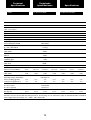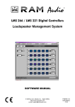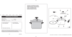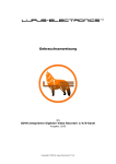
1
Professional Power Amplifiers
6000-9000-12000
9004-9044-12004-12044
V Series
OPERATION MANUAL
NOTICE D’EMPLOI
BEDIENUNGSANLEITUNG
© 2011 by C.E. Studio-2 s.l. - Spain (EEC)
http://www.ramaudio.com
e-mail: [email protected]
P-6546-564
QXPDQXDoc
4/11
SAFETY
PRECAUTIONS
WARNING:
SICHERHEITSHINWEISE
ACHTUNG!:
AVERTISSEMENTS
RÈGLES DE SÉCURITÉ:
CAUTION
VORSICHT
ATTENTION
RISK OF ELECTRIC SHOCK
DO NOT OPEN
GEFAHR EINES
ELEKTRISCHEN SCHLAGES.
NICHT ÖFFNEN!
RISQUE DE CHOC ÉLECTRIQUE
NE PAS OUVRIR
To avoid fire or electrocution risk do not
expose the unit to rain or moisture.
To avoid electric shock, do not open the
unit. No user serviciable parts inside. In
the case of disfunction, have the unit
checked by qualified agents.
Class I device.
Um Brand oder elektrische Schläge zu
vermeiden, darf diese Einheit
keiner starken Luftfeuchtigkeit oder
Regen ausgesetzt werden.
Um elektrische Schläge zu vermeiden,
öffnen Sie diese Einheit nicht. Bei
Reparaturbedarf wenden Sie sich an
qualifiziertes Personal.
Pour écarter tout risque d’incendie ou
d’électrocution, ne pas exposer l’appareil à la pluie ni à l’humidité.
Afin d’éviter tout risque, ne pas ouvrir
l’appareil. Ne confier l’entretien de l’appareil qu’à du personnel technique qualifié et agréé.
Appareil de Classe I.
Es handelt sich um ein Gerät der
Klasse I.
IMPORTANT:
IMPORTANT:
IMPORTANT:
Clean the front panel filters regularly.
Extract the filters removing the front
panel grid unscrewing the thumbscreews placed at the sides of the grid.
Clean the filters using water and detergent. Place the grid filter introducing
first the internal side and screwing the
thumbscrew.
Clean the front panel filters regularly.
Extract the filters removing the front
panel grid unscrewing the thumbscreews placed at the sides of the grid.
Clean the filters using water and detergent. Place the grid filter introducing
first the internal side and screwing the
thumbscrew.
Clean the front panel filters regularly.
Extract the filters removing the front
panel grid unscrewing the thumbscreews placed at the sides of the grid.
Clean the filters using water and detergent. Place the grid filter introducing
first the internal side and screwing the
thumbscrew.
Grid Filter Detail
1
INDEX
INHALTSVERZEICHNIS
TABLE DES
MATIÈRES
0 Safety Precautions
0 Sicherheitshinweise
0 Avertissements
1 General Information
1.1 Introduction
1.2 Main Characteristics
1 Allgemeine Anweisungen
1.1 Einleitung
1.2 Allgemeine Eigenschaften
1 Informations Générales
1.1 Introduction
1.2 Caractéristiques générales
2 Controls: Where and What?
2.1 Front Panel
2.2 Rear Panel
2 Lokalisierung der Funktionen
2.1 Frontplatte
2.2 Rückplatte
2 Commandes et fonctions
2.1 Panneau avant
2.2 Panneau arrière
3 Installation and Operation
3.1 Connections
3.1.1 Dual Channel Mode
3.1.2 Link Channel Mode
3.1.3 Bridge Channel Mode
3.2 Configuration
3.3 Troubleshooting
3 Anschluss- und Inbetriebnahme
3.1 Anschlüsse
3.1.1 Dual Kanalmodus
3.1.2 Link Kanalmodus
3.1.3 Bridge Kanalmodus
3.2 Konfiguration
3.3 Problemlösung
3 Installation et mise en route
3.1 Branchements
3.1.1 Mode DUAL
3.1.2 Mode LINK
3.1.3 Mode BRIDGE
3.2 Configuration
3.3 Dysfonctionnements éventuels
et dépannage.
4 Technical Specifications
4.1 Protection Systems
4.2 Data
4 Technische Spezifikationen
4.1 Schutzschaltungssysteme
4.2 Technische Daten
©2011 by C.E. Studio-2 s.l.
Pol.Ind. La Figuera
C/Rosa de Luxemburgo nº34
46970 Alaquas - Valencia - SPAIN
Phone: +34 96 127 30 54
Fax: +34 96 127 30 56
http://www.ramaudio.com
e-mail: [email protected]
P-5435-634 QXPDQXDoc 4/11
RAM Audio®, PMS™, SSP™, ICL™,
FCM™ and QuantaPulse™ are registered trademarks of C.E. Studio-2 s.l..
All other names are trademarks of their
respective companies.
2
4 Spécifications
4.1 Systèmes de Protection
4.2 Données téchniques
General Information
Allgemeine
Anweisungen
1.1 Introduction
The V Series devices feature two or four
channel models, ready for rough handling in the touring world. For this purpose, V Series amps implement oversized high efficiency regulated power
supply with PFC front end to deliver
their full performances independently of
mains status. This together with oversized high efficiency audio power
stage, forced front to back cooling
through a component-free path with
removable front panel dust filters,
improved rugged mechanical design
with even weight distribution, full digital
control from LCD display on the front
panel... Resulting in: just power, reliability and robustness for your touring
gigs!
1.2 Main Characteristics
• PFC QuantaPulse™ Regulated Dual
SMPS
• Digital Control with extra large LCD
display user interface
• Channel Temperature and Output
Level Monitor in the LCD
• USB port for firmware update and
DSP control
• 25 position Gain, Bridge mode, Input
Links and ICL, front panel configurable
• Digital Potentiometers with Encoder
control
• RAM Audio Power Management
System
• Hi Efficiency, Heavy Duty Audio Power
section for extreme use
• Easily removable front panel dust filters
• Industry standard Neutrik® XLR and
Speakon® connectors
• Optional low latency 24bits 96kHz
high performance DSP with post-DSP
signal links and Ethernet control. It
features up to 70 meters input delay.
• Optional EtheRAM II Ethernet monitor
and control system
• Optional EtherSound™/CobraNet™
audio transport and AES/EBU Digital
input
3
Informations
Générales
Controls:
Where and What?
Lokalisierung der
Funktionen
Commandes et
Fonctions
2.1 Front Panel
2.1 Frontplatte
2.1 Panneau Avant
See Figure 1
Siehe Fig. 1
Voir Fig. 1
1 Configuration and signal attenua-
tion level control knobs: Permit
independent control of each channel’s attenuation and change the
amplifier configuration. See page
10.
2 SIGNAL: This LED indicates pres-
ence of signal at the inputs.
TEMP: This LED shows temperature protection is active.
PMS: LED indicating PMS in operation (see page 13)
ICL: LED indicating Intelligent Clip
Limiter in operation (see page 13).
1 Lautstärkeregler: diese ermögli-
chen die Signalstärke am Ausgang.
siehe Seite 10.
1 Configuration et Atténuateurs de
signal d’entrée crantés: réglage
du niveau d’entrée indépendant sur
chaque canal. Voir page 10.
2 SIGNAL: Wachanzeige des einge-
henden Signals.
TEMP: LED-Anzeige leuchtet wenn
der Schutz vor Überwärmung eingeschaltet ist.
PMS: Die LED zeigt an, dass das
PMS in Betrieb ist (siehe Seite 13)
ICL: Die LED zeigt an, dass der
Intelligent Cliplimiter arbeitet (siehe
Seite 13).
2 SIGNAL: indique la présence de
signaux d’entrée.
TEMP: signalisation par LED de
temperature excessive.
PMS: signalisation par LED de le
fonctionnement de le système PMS
(voir page 13).
ICL: signalisation par LED de le
fonctionnement de le système ICL
(voir page 13).
3 Beleuchteter Hauptstromschalter:
3 Main Power Switch:
Position I: Connects the amplifier's
current feed. (Blue LED on).
Position O disconnects the Power.
Position II (optional): Stand-by
Mode. The Amp's Power is activated
remotely via Ethernet. (Amber LED).
Position I: Schaltet die Endstufe ein.
(Blaue LED leuchtet).
Position O Schaltet die Endstufe
aus.
Position II (optional): Stand-by
Modus. Die Endstufe kann über
Ethernet eingeschaltet werden.
(Gelbe LED).
4 Display: See page 10.
3 Power:
Position I: Connecte l'appareil au
courant, (LED Bleue allumée).
Position O: Interruption de la mise
sous tension.
Position II (optional): Mode stand-by,
la mise sous tension s'effectue a
distance via Ethernet, (LED Orange
allumée).
4 Display: siehe Seite 10.
4 Display: voir page 10.
5 USB Connector for firmware
upgrade and optional DSP control.
5 USB Connector for firmware upgra-
de and optional DSP control.
5 USB Connector for firmware upgra-
de and optional DSP control.
Front Panel
1
4
1
5
2
3
4
Controls:
Where and What?
Lokalisierung der
Funktionen
Commandes et
Fonctions
2.2 Rear Panel
2.2 Rückplatte
2.2 Panneau Arrière
See Figure 2
Siehe Fig. 2
Voir Fig. 2
1 Signal Input: Female Neutrik® XLR
1 Eingangssignal: Neutrik®-XLR
1 Connecteurs Neutrik® XLR (feme-
Connectors for the amplifier’s signal
input.
Buchsen für den Signaleingang der
Endstufe.
lle) d’entrée des signaux de modulation.
Signal Link: Male Neutrik® XLR
Connectors for daisy chaining input
signal to other amplifiers (parallel
connected to female input connectors).
Signallink: Parallele XLR-Ausgänge
zur Zusammenschaltung der
Eingangssignale mehrerer
Endstufen.
Connecteurs Neutrik® XLR (mâle),
sortie des signaux d’entrée pour la
mise en parallèle d’autres amplis.
2 Lautsprecheranschluss: Neutrik
2 Speaker connectors: Neutrik®
Speakon to connect the speakers.
Speakonstecker zum Anschluss an
Lautsprecher.
3 Mains Power Cord: to connect the
3 Mains Power Cord: to connect the
amplifier to the mains network. The
colour code is:
Blue: Neutral
Brown: Live, single phase
Yellow-green: Protective Earth
amplifier to the mains network. The
color code is:
Blue: Neutral
Brown: Live, single phase
Yellow-green: Protective Earth
2 Speakon de sortie pour le branche-
ment des HP.
3 Mains Power Cord: to connect the
amplifier to the mains network. The
color code is:
Blue: Neutral
Brown: Live, single phase
Yellow-green: Protective Earth
Rear Panel
2
2
1
3
5
2
Installation and
Operation
Anschluss und
Inbetriebnahme
Installation et
mise en service
3.1 Connections
3.1 Anschlüsse
3.1 Branchement
The Power switch must always be on
the “Off” position before plugging the
amp to a properly earthed mains socket (170-265V AC). The colour code is:
Blue: Neutral
Brown: Live, single phase
Yellow-green: Protective Earth
Bevor Sie diese Einheit an eine
SHUKO-Steckdose anschließen, schalten Sie den Hautstromschalter aus. The
colour code is:
Blue: Neutral
Brown: Live, single phase
Yellow-green: Protective Earth
Veillez à ce que l’interrupteur de mise
en service soit en position “Off” avant
de brancher l’appareil sur une prise secteur avec mise à la terre (170-265V
AC). The colour code is:
Blue: Neutral
Brown: Live, single phase
Yellow-green: Protective Earth
The input signal fed to the amplifier can
be either balanced or un-balanced. The
drawing below describes both ways to
wire an XLR connector for the purpose.
Das Eingangssignal kann entweder
symmetrisch oder unsymmetrisch sein.
Für den Anschluss siehe Zeichnung.
Balanced Signal: Connect pin 1 to
Ground, pin 2 to Signal + (hot) and pin
3 to Signal - (cold).
Symmetrisches Signal: Die Belegung
der XLR Pins ist wie folgt: 1-Masse, 2Positives Signal (hot), 3-Negatives
Signal (cold).
Unbalanced Signal: Connect Pin 1 to
Ground, pin 2 to Signal and pin 3 to
Ground.
Asymetrisches Signal: Die Belegung
der XLR Pins ist wie folgt: 1-Masse, 2Signal, 3-Masse.
L’appareil peut fonctionner avec des
signaux symétriques ou assymétriques.
La figure ci-dessous indique le câblage
des connecteurs XLR pour les deux
cas.
Câblage Symétrique: souder la broche
1 à la masse, la broche 2 au point
chaud (+), et la broche 3 au point froid
(-).
Câblage Assymétrique: souder les
broches 1 et 3 à la masse, et la broche
2 au signal.
Balanced Wiring
1- Ground
2- Signal +
3- Signal -
Unbalanced Wiring
1- Ground
2- Signal
3- Ground
Important!: If a connection is done with
a un-balanced line and pin 3 on the
XLR is not connected to ground, a 6 dB
loss occurs in the line and only a quarter of the amplifier power is produced.
ACHTUNG! Wenn Sie ein asymetrisches Signal anschließen und Pin 3 nicht
an Masse anschließen, erzeugt dies
einen Verlust von 6dB (1/4 der Leistung
der Endstufe) am Ausgangssignal.
The amplifiers provides, for each channel, a female XLR Connector (Signal
Input) paralleled to a male XLR to daisy
chain several amplifiers with the same
signal line (LINK).
Die Endstufe verfügt über eine parallele
XLR-Buchse für die
Zusammenschaltung mehrerer
Endstufen.
6
Important: Si on effectue le branchement d’un signal asymetrique sur le
connecteur XLR sans relier la broche 3
à la masse, une perte de 6dB sera
constatée , ce qui se traduira par une
perte du 75% de la puissance de sortie.
Le amplificateurs est muni des connecteurs XLR mâle pour la mise en
parallèle de plusieurs amplificateurs
avec les mêmes signaux d’entrée.
Installation and
Operation
Anschluss und
Inbetriebnahme
The amplifier can operate on three different configurations: DUAL, LINK or
BRIDGE. The connections for the three
modes are different.
Es gibt drei Funktionsmöglichkeiten dieser Endstufe: Dual, Link und Bridge. Die
Anschlüsse sind in den drei Fällen
unterschiedlich.
L’amplificateur peut fonctionner en
mode stéréo, parallèle ou ponté
(Bridge). Le branchement est différent
pour ces trois modes.
3.1.1 DUAL Channel Mode
3.1.1 DUAL Kanalmodus
3.1.1 Mode Stéréo
See Figure 3
Siehe Fig. 3
Voir Fig. 3
- Set the Amplifier Mode to “DUAL”.
- Select the chosen Gain (Default setting 32dB).
- Connect the signal lines to the female
XLR connectors on all channels.
- Connect the speakers’ lines to the corresponding Speakon on the amp
respecting the polarity.
- Use the level control knob on the front
panel to adjust each channel independently.
- Each signalling LED group will show
its corresponding channel status.
- Stellen Sie den Modusschalter auf die
Modus “Dual”.
- Bitte wählen Sie den
Eingangspegelwert (Werkseinstellung
32 dB).
- Schließen Sie alle Eingangssignale an
ihre entsprechenden XLR-Buchsen.
- Schließen Sie die Lautsprecher an die
entsprechenden Speakon an, bitte die
Polarität ist beachten.
- Benutzen Sie die Lautstärkeregelung
der entsprechenden Kanäle um den
gewünschten Lautstärkepegel zu erreichen.
- Die LED-Anzeigen geben den Status
der beiden Kanäle an.
3.1.2 LINK Channel Mode
See Figure 4
3.1.2 LINK Kanalmodus
- Operate as Dual Channel Mode with
the signal input linked to another adjacent channel.
Siehe Fig. 4
3.1.3 BRIDGE Channel Mode
- Gehen Sie wie im Dual-ChannelModus vor, wobei das Eingangssignal
mit einem angrenzenden Kanal verbunden ist.
See Figure 5
- Set the configuration mode to
“BRIDGE” (see page 9).
- Select the chosen Gain (Default setting 32dB).
- Connect a signal line to input female
XLR Channel “A” (or Ch-C in 4 channel models).
- Connect the speaker line to the
Channel A Speakon (or Ch-C in 4
channel models) wired to +1 and -2. In
this way pin +1 is positive.
- Use Channel-A (or Ch-C in 4 channel
modes) control knob to adjust the
amp’s output.
- The signalling LED groups will show
the single channel status.
WARNING! The “-“ pins, do not
have to be Ground!
Installation et
mise en service
- Sélectionner le mode “DUAL”.
- Selectionnez le sensibilité choisie
(réglage usine 32dB).
- Bancher les signaux d’entrée aux
fiches XLR femelles de touts les
canaux.
- Brancher les haut-parleurs sur les
Speakon en respectant les polarités.
- Utiliser les atténuateurs d’entrée en
face-avant pour régler le niveau de
sortie de chaque canal.
- Les indicateurs LED afficheront le
stade de chaque canal.
3.1.2 Mode LINK
Voir Fig. 4
- Utiliser l'ampli comme en mode Dual
mais avec le entrée de signal “linked”
au le canal consécutif.
3.1.3 Mode Ponté (BRIDGE)
Voir Fig. 5
3.1.3 Bridge Kanalmodus
Siehe Fig. 5
- Setzen Sie den Konfigurationsschalter
auf die Modus “BRIDGE” (Siehe Seite
9).
- Wählen Sie den Einganspegelwert auf
dem Schalter (Werkseinstellung 32
dB).
- Schließen Sie das Eingangssignal an
die XLR-Buchse “A” an (oder Kanal C
bei 4-Kanalmodellen).
- Schließen Sie den Lautsprecher an
den Kanal “A” Speakon (oder Kanal C
bei 4-Kanalmodellen) verkabelt mit +1
und -2 (+1 ist positiv).
- Benutzen Sie Kanal A (oder Kanal C
bei 4-Kanalmodellen) Potentiometer
für die Regulierung des Endstufenausganges.
- Die LED-Anzeigen werden den Status
des Ausgangkanals angeben.
ACHTUNG! The “-“ pins, do not
have to be Ground!
7
- Sélectionner le mode BRIDGE (voir
page 9).
- Selectionnez le sensibilité choisie
(réglage usine 32dB)
- Brancher le signal modulation sur le
connecteur XLR (femelle) du Canaux
“A”. (ou Canaux “C” pour 4 canal
modèles).
- Brancher les HP sur les (+1, -2) des
Speakons de sortie du canaux A ou C.
Le +1 est la borne positif dans ce
mode de fonctionnement.
- Utilisser les atténuateur d’entrée du
Canaux A (ou C pour 4 canaux modeles) pour ajuster le signal de sortie.
- Les rangées de LED afficheront le
niveau de sortie.
AVERTISSEMENT! Le “-“ ne est
pas masse!
3
Dual Channel
2 Ch models
4
Link Inputs
2 Ch models
5
Bridge Mode
2 Ch models
8
3
Dual Channel
4 Channel models
4
Link Inputs
4 Channel models
5
Bridge Mode
4 Channel models
Bridge + Dual Mode
3 Channels Mode
9
Installation and
Operation
3.2 Configuration
Main Screen: shows the current preset name (“G32dBDual-UnLink” as default), and the channel attenuation. As
an option you can show the output VUmeter. The “M”
appears at the top right corner if the preset has been
changed from the last load. You can change each channel
amplifier level turning the encoder knob for each channel.
1-G32dB-Dual-UnLink
M
0dB
0dB -3dB -6dB
Menu navigation: to access to the Menu screen you have to press the CH-A encoder knob from the Main Screen. Turning the
CH-A encoder knob you access to the different options. When you press the CH-A encoder knob you start the Edit mode (only
for some options), and a “E” blinking letter appears at the top right corner. Using the four encoder knobs you can change the
different options. Pressing another time the CH-A encoder knob you finish the Edit mode, and return to the Menu screen. The
last menu option is Exit to return to the main screen or Exit + Dial Lock to protect the encoder knob from any unwanted action.
If you use this option you can unlock the system pressing the CH-A knob for 5 seconds. If you need to limit the access to the
configuration you can define a password from the Password Manager in the Amplifier Setup section. The Menu development
are the next:
Amplifier Setup: You access to the Setup Menu, where
you can change parameters as Inputs Link, Gain, Bridge
Mode... Also you can change the preset and limit the
access using a Password. See Amplifier Setup section on
next page for more details.
Amplifier Setup
Channel Temperature: Show the percent of maximum
temperature for each channel. When you are near the
100% the PMS system limits the power output to avoid
reach the overheating protection.
Channel Temperature
60%
50%
60%
70%
Display Mode: Change between Channel Attenuation.or
Vu meter mode in the Main Screen.
Display Mode
VU meter
Operating Time: shows the amplifier total time operation.
Operating Time
45h 34min
Firmware Version: shows the Amp Control firmware version. You can upgrade it using the USB port.
Firmware Version
Amp Control v1.2b
10
Installation and
Operation
Amplifier Setup: when you are in the Main Menu and access to the Amplifier Setup section, you can change different amplifier
parameters, change the current preset and protect the access using a password. The Menu development for this section is the
next:
Preset Manager
Load Save
Del
Inputs Link
IN-A IN-B
IN-C
Preset Manager: you can change quickly the amplifier preset
configuration. To access to any option you have to enter in
Edit mode (pressing CH-A knob) and turn the corresponding
encoder: CH-A for Load, CH-B for Save, CH-C for Delete and
CH-D for Restore default. Select a preset number from 0 to 9.
Rest
Inputs Link: you can Link the input signal to the next channel. Enter in Edit mode and turn the CH-B, CH-C or CH-D
knob to link the input to the previous channel.
IN-D
WARNING! You have to remove the
input connector of the linked channel!
Amplifier Gain: you can change independently the amplifier
gain for each channel from 26dB to 38dB (0.5dB steps). Enter
in Edit mode and use the corresponding channel knob to
modify it.
Amplifier Gain [dB]
32dB 32dB 32dB 32dB
Amplifier Mode
BRDG BRDG DUAL
Amplifier Mode: it configures the amplifier in Dual or Bridge
mode. In Edit mode use the CH-A or CH-C channel knob to
change the option.
DUAL
Attenuators Link: you can link all attenuators to modify the
output level for all channels simultaneously. When you
change this option to Enabled, you modify the attenuation for
all channels using any channel knob.
Attenuators Link
Disabled
ICL Clip Limiter: you can turn on or turn off the ICL Clip
Limiter for all channels. We recommend to you to work with
this option enabled to avoid any damage to the speakers.
ICL Clip Limiter
Enabled
Password Control: you can define a password to prevent
any modification of the amplifier configuration. When you turn
on this option, you have to introduce a password using the
four knob encoders, and confirm it. After that, you need to
introduce this password each time you want to modify the
amplifier configuration. There is a generic password which
you can use to disable the Password Control, it is: 5 5 5 5
Password Control
Enabled
11
Installation and
Operation
Anschluss und
Inbetriebnahme
Installation et
mise en route
3.3 Troubleshooting
3.3 Problemlösung
3.3 Dysfonctionnements éventuels
In the event of incorrect connection or
misfunctioning, the amp will activate
one or more of its LED to warn about
the problem.
Sollte sich eine Fehlfunktion ergeben,
wird diese durch die LED-Anzeigen auf
der Frontplatte angezeigt. Es gibt folgende Möglichkeiten:
En cas d’utilisation incorrecte ou de
dysfonctionnement, une ou plusieurs
LED seront allumées pour indiquer la
nature du problème.
SGNL TEMP PMS
ICL
Correct function: SGNL lights to indicate signal presence.
SGNL TEMP PMS
ICL
ICL: The Intelligent Clip Limiter is operating (see page 10).
SGNL TEMP PMS
ICL
No Signal: No Input Signal is reaching
the amp.
SGNL TEMP PMS
ICL
Overheating: The amplifier has reached the maximum operational temperature. Most common cause is: the normal air flow is blocked, accumulated
dirt, dust or object leaning against the
grill. Check and clean periodically.
SGNL TEMP PMS
ICL
SGNL TEMP PMS
ICL
Korrektes Arbeiten: SGNL leuchtet
wenn Eingangssignal vorhanden ist.
SGNL TEMP PMS
ICL
SGNL TEMP PMS
ICL
Surchauffe: l’amplificateur a atteint sa
plus haute température interne admissible. Le plus souvent ceci est dû à un
blocage ou à l’obturation des voies de
ventilation.
ICL
- The amplifier is in power-on sequence,
where output is inhibited until the amp
circuits are ready to operate.
- Die Endstufe befindet sich im
Anschaltevorgang, das
Ausgangssignal wird so lange
gehemmt bis die Enstufe voll funktionsbereit ist.
- Die Innentemperatur steigt aufgrund
ungünstiger Arbeitsbedingungen nahe
des Grenzwertes bei dem die automatische Ausschaltefunktion aktiviert wird
um eine Überhitzung des Systems zu
vermeiden.
- Überhöhter Netzstromverbrauch.
12
ICL: .Fonctianement du Limiteur
Intelligent d'écretage (voir page 10).
ICL
PMS: Mehrere Ursachen können dieses
LED auslösen, die häufigsten sind:
- Excessive mains current consumption.
ICL
Aucun Signal n’arrive à l’Ampli.
PMS: Several causes can trigger this
LED, most common are:
- The internal temperatures rise to near
thermal shutdown point due to unfavourable operating conditions.
SGNL TEMP PMS
SGNL TEMP PMS
Überhitzung: Die Endstufe hat die
maximale Arbeitstemperatur erreicht.
Die häufigste Ursache ist
Verschmutzung oder Blockierung der
Luftein- und Austritte. Es ist ratsam
diese regelmäßig zu säubern.
SGNL TEMP PMS
Fonctionnement correct: SGNL Diode
Verte allumée
ICL
Kein Eingangssignal: Kein
Eingangssignal vorhanden.
SGNL TEMP PMS
ICL
ICL
ICL: Der Intelligent Clip Limiter ist in
Betrieb (Siehe Seite 10).
SGNL TEMP PMS
SGNL TEMP PMS
SGNL TEMP PMS
ICL
PMS: PMS Diode Orange allumée.
Plusieurs anomalies peuvent déclencher cet affichage. Les plus courantes
sont:
- L'ampli se trouve en situation de mise
sous tension et les sorties se trouvent
inhabilitées jusqu'à ce que tous les circuits soient prêts a fonctionner.
- L'ensemble de la température interne
de l'ampli s'approche du point de mise
en attente à cause de conditions de
fonctionnement défavorables.
- Consommation de courant excessif.
Protection Systems
Schutzschaltungssysteme
Systèmes de
Protection
PMS™ - Power Management System
PMS™ - Power Management System
PMS™ - Power Management System
This is a complete set of protections that
monitors the main amp parameters (load
status, signal input, temperature, current,
etc.) in order to draw from the power supply only the precise amount of current
required to maintain safe operation during
hazardous or extreme working conditions.
Vollständiges Set von Schutzfunktionen
das die wichtigsten Endstufenparameter
überwacht (Auslastung, Signaleingang,
Temperatur und Stomstärke) um vom
Netzanschluss nur die Menge Strom zu
beziehen, die für den betriebssicheren
Arbeitsablauf notwendig ist
This system controls the amount of power
that the amp delivers under three basic
circumstances:
Dieses System reguliert die von der
Endstufe abgegebenen Leistung in 3
Fällen:
1.- The power-on sequence, where output
is inhibited until the amp circuits are ready
to operate. This routine is repeated at
every restart, not just when the power
switch is activated.
1.- Anschaltevorgang: Der Ausgang wird
gehemmt bis die Endstufe voll funktionsbereit ist. Dieser Vorgang wiederholt sich
bei jedem Neustart, nicht nur wenn der
Leistungsschalter aktiviert wurde.
2.- When internal temperatures rise to
near thermal shutdown point due to
unfavourable operating conditions. Here
the system takes control, restricting current so as to maintain operational continuity at the precise power level which the
amp is capable of withstanding at that particular moment.
2.- Wenn die Innentemperatur aufgrund
ungünstiger Arbeitsbedingungen nahe des
Grenzwertes steigt, bei dem die automatische Ausschaltefunktion aktiviert würde,
um eine Überhitzung des Systems zu vermeiden. In diesem Fall übernimmt das
System die Kontrolle und reduziert die
Stromzufuhr auf ein Niveau, dass die
Endstufe in dieser Situation aushalten
kann.
Ceci est un ensemble complet de protections qui surveille les paramètres principaux de l'ampli: état de l'impédance (charge), signal d'entrée, température, courant,
etc. pour obtenir de l'alimentation la quantité précise minimum de courant et ainsi
permettre à l'ampli de continuer à fonctionner en sécurité dans des conditions extrêmes, ou voire dangereuses au maintien de
son intégrité électronique.
Ce système contrôle la quantité de courant que l'ampli peut utiliser dans les circonstances suivantes:
1.- Lors de la mise sous tension, ou la sortie est coupée jusqu'a ce que l'ampli est
100% prêt dans tous ses circuits. Ce processus est repeté, non seulement a la
mise en marche, mais chaque fois que
l'ampli se remet en fonctionnement.
2.- Quand la température interne de l'ampli est proche de la coupure automatique
de sécurité, (thermal shutdown), dans des
conditions de fonctionnement adverses.
Dans ce cas, le système prend le contrôle,
et oblige l'alimentation a ne délivrer que le
courant nécessaire a maintenir le fonctionnement, au niveau que l'ampli est capable
de maintenir à ce moment précis, dans
des conditions données.
3.- Dans le cas de consommation excessive de courant. Cette éventualité ne se
pressente que dans des conditions de
laboratoire lors de tests prolongés avec
des signaux sinusoïdaux ou dans les cas
de realimentation acoustique prolongée
sur la scène. Ici le PMS prend le contrôle
pour éviter d'endommager les haut-parleurs, de faire sauter les systèmes de protection du secteur ou même les fusibles.
3.- Excessive mains current consumption.
This event only occurs either under laboratory conditions (long term sinusoidal signal
testing with dummy loads) or, for example,
in field applications in conditions of prolonged acoustic howl-round. Here PMS
takes control to avoid any damage to the
speakers and to prevent the mains breaker from tripping or the fuses blowing.
ICL2™ - Intelligent Clip Limiter
The RAM Audio ICL2 is an anticlip system
to avoid speaker failure and provide more
acceptable sound quality even when clipping occurs. With the ICL2 system you
don't lose the music “punch” but the
speakers are kept under control.
SSP™ - SOA Sentry Protection
SOA Sentry protection effectively limiting
the power that the amp could deliver into
an incorrect load or to a direct short-circuit. This avoids power transistor failure.
FCM™ - Faulty Channel Management
Faulty Channel Management system to
avoid entire device shutdown.
3.- Überhöhter Stromverbrauch: Diese
Situation stellt sich ausschließlich unter
Laborbedingungen ein (in sinusförmigen
Langzeitsignaltests mit Dummylasten oder
in langanhaltenden akustischen Feedback
Bedingungen. Hier greift das PMS System
ein um eine Schädigung der Lautsprecher
zu vermeiden und um zu verhindern dass
der Hauptunterbrecher ausgelöst wird oder
die elektrischen Sicherungen durchbrennen.
ICL™ - Limiteur Intelligent d'écrêtage
ICL™ - Intelligent Clip Limiter
Das RAM Audio ICL2 ist ein Anticlipsystem
das das Versagen der Lautsprecher vermeidet und auch wenn Clipping auftritt
noch eine bessere Tonqualität gewährleistet. Mit dem ICL2 System verlieren Sie
den “Punch” nicht, und der Lautsprecher
arbeitet kontrolliert.
Le ICL2 de RAM Audio est un système
anti-écrêtage qui permet un rendement
des haut-parleurs optimisé et offre un meilleur résultat auditif quand l'écrêtage est
pressent. Le ICL2 permet à la musique de
garder son punch mais sauvegarde les
haut-parleurs.
SSP™ - SOA Sentry Protection
SSP™ - SOA Sentry Protection
SOA Die Leistung, die die Endstufe an
inkorrekte Lasten oder an einen
Kurzschluss abgeben könnte wird wirksam
limitiert. Dies verhindert die Zerstörung der
Leistungstransistoren.
FCM™ - Faulty Channel Management
Faulty Channel Management system to
avoid entire device shutdown.
13
Le SOA est un système sentinelle qui limite de manière efficace le courant que l'ampli peut donner sous une charge inadéquate ou sous court-circuit direct. Ce
système protége les transistors de sortie.
FCM™ - Faulty Channel Management
Faulty Channel Management system to
avoid entire device shutdown.
Technical
Specifications
Technische
Spezifikationen
4.2 Data
Spécifications
4.2 Technische Daten
4.2 Données techniques
Technical Specifications
V-6000
V-9000
V-12000
V-9004
V-9044
V-12004
V-12044
@ 2Ω
2x 3025 W
2x 4400 W
2x 5900 W
4x 2260 W
-
4x 3025 W
-
@ 4Ω
2x 1600 W
2x 2300 W
2x 3100 W
4x 1150 W
4x 2200 W
4x 1600 W
4x 2950 W
@ 8Ω
Output Power
1kHz, 1.0% THD+N
2x 820 W
2x 1200 W
2x 1600 W
4x 600 W
4x 1150 W
4x 820 W
4x 1550 W
Bridge @ 4Ω
6050 W
8800 W
11800 W
2x 4520 W
-
2x 6050 W
-
Bridge @ 8Ω
3200 W
4600 W
6200 W
2x 2300 W
2x 4400 W
2x 3200 W
2x 5900 W
Frequency Response
Power Bandwidth ±0.25dB
20Hz-20kHz
Phase Response
@ 1 watt 20Hz-20kHz
±15 deg
Total Harmonic Distortion
20Hz-20kHz
<0.05%
Intermodulation Distortion
SMPTE
<0.05%
Damping Factor
20-500Hz @8Ω
>500
Crosstalk
20Hz-1kHz
>80dB
Voltage Gain
26dB to 38dB (0.5dB steps)
Sensitivity
Rated Power (26/32/38dB Gain)
4/2/1 V
4.9/2.5/1.2 V
5.7/2.8/1.4 V
3.5/1.7/0.9 V
4.8/2.4/1.2 V
4.1/2/1 V
5.6/2.8/1.4 V
113dB
115dB
116dB
112dB
115dB
113dB
116dB
Signal-to-Noise Ratio
20Hz-20kHz
Required AC Mains
Operating Voltage (50Hz-60Hz)
170V-265V AC
Power On Idling (@230V)
0.5 A
0.5 A
0.5 A
0.5 A
0.5 A
0.5 A
0.5 A
1/8 Rated Power (@230V min. Z)
7A
10 A
13 A
11 A
10 A
14 A
13 A
12-26.5
12-26.5
12-26.5
12-26.5
Dimensions
W x H x D (mm)
483x89x460
W x H x D (inches)
19x3.5x18.1
Weight
Net (Kg-Lbs)
10-22.1
12-26.5
12-26.5
Protections
Soft-start, Turn-on Turn-off transients, Muting at turn-on, Over-heating, DC, RF, Short-circuit, Open or mismatched loads, Overloaded
power supply, Mains Overvoltage, ICL™, PMS™, SSP™ and FCM™
14
Manufactured in the EEC by C.E. Studio-2 s.l.
Pol. Ind. La Figuera - C/Rosa de Luxemburgo, nº 34
46970 Alaquas - Valencia - SPAIN
Phone: +34 96 127 30 54 Fax: +34 96 127 30 56
http://www.ramaudio.com e-mail: [email protected]