1
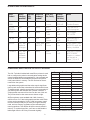
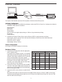
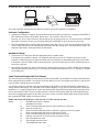
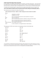
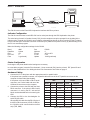
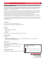
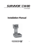
VOLUME 13, July 1997
Setting Up Eltron Printers
OVERVIEW OF SETTING UP ELTRON PRINTERS
Unlike most printers having only enough buffer storage for a
single print, the Eltron printers have a standard 128K
memory for storing multiple label data within the printer. In
addition, all but one of the Eltron printers come with a
Create-A-Label (CAL) Tools software program which the
installer uses to easily create a custom label for downloading
into the printer's memory. The label created is then resident
in the printer—rather than the digital indicator—and the PC
that created the label can be permanently disconnected.
This unique approach to label creation and storage offers
great advantages to the user and installer, but the new technology requires some non-traditional set up procedures different than most printers. This publication will guide you through those procedures.
The basic steps in setting up an Eltron printer with a custom label are:
1. Connect the printer and IBM-compatible PC together with either RS-232 serial or Centronics parallel cables.
2. Load the supplied CAL Tools software program onto the PC’s hard drive.
3. Create the label on the PC.
4. Download the label to the printer.
5. Disconnect the PC and connect the scale indicator to the printer with an RS-232 cable.
6. Set up the indicator to provide the interface commands necessary to operate the Eltron printer. With some
indicators, the optional keyboard display unit (KDU) may be necessary for proper interfacing. The KDU will also
be necessary if alphanumeric operator entries are desired during weighing operations.
7. Begin weighing operations.
For detailed setup procedures using Eltron printers with selected RLWS scales and indicators, see pages 3–10.
THE OPTIONAL KEYBOARD DISPLAY UNIT (KDU)
The Eltron KDU is used for three main purposes:
• Choosing one of several label formats stored in a printer or printing all label
formats stored in a printer
• Calling up product IDs or entering other alphanumeric information.
• Establishing a communication interface with Eltron printers. See the
interface chart on the following page for RLWS products which require
the KDU to interface to Eltron printers.
Keyboard Display Unit (KDU)
INTERFACE CHART FOR RLWS PRODUCTS
RLWS
Product
Direct
Operates Additional
interface with
hardware
possible? KDU?
needed?
Baud rate,
Bits, Parity
Terminal
character,
EOL Delay
Notes
IQ plus
310A
No
Yes
KDU
4800
8 none
CR/LF
1500 mS
Format=CC
Printer=Generic
IQ plus
800/810
Yes
No
None
9600
8 none
CR
0 mS
Turn off Truck
In/Out program
IQ700
Yes
No
None
9600
7 odd
CR
0 mS
14=Simplex
14.1=GTN
CW-80
No
Yes
KDU
4800
8 none
CR
0 mS
Pfunction=AP3
PR out=CCC
IQ6500
Yes, with No
optional
changes
Cable, part 9600
# 41279
8 none
CR
0 ms
Eltron option, part
# 41278, must be
factory-installed
PK280SS
Yes, with No
optional
software
program
None
CR
0 mS
Requires Program
# RC21A306.
Graphics created
are stored as
Form 7, 8, or 9
9600
8 none
Interface Chart: Eltron Printers to RLWS Products
DOWNLOADING LABELS CREATED IN CAL TOOLS TO THE PRINTER
The CAL Tools disk included with most Eltron printers is used
both to configure the printer's communication settings and to
create formatted labels on an attached PC. Once created and
saved, the labels are downloaded to the printer and permanently stored there in memory. The PC can then be disconnected from the system.
Large labels with graphics and bar codes require significant
memory and can be slow to download in serial transfer format.
To speed transfer, parallel communication is recommended. If
your Eltron printer was ordered with a parallel interface, a
34-pin parallel connector will be found on the rear of the unit.
The pin functions for that connector are shown at right.
All Eltron printers come standard with 128K of memory,
sufficient for a 4"x 5" label with graphics and bar codes. Each
printer can be upgraded to 512K in 128K increments. Install
as much memory initially as you think you might eventually
need, as future memory upgrades require reallocating the
memory partitions. This deletes all labels currently stored in
memory. To replace those files, you’ll have to download the
labels again from the PC files you created originally.
2
Pin
Function
Transmitter
1
–Strobe
Host
2-9
Data 0...7
Host
10
Busy
Printer
11
Busy
Printer
12
Paper empty
Printer
13
Select
Printer
14-15
N/C
16
Signal ground
17
Chassis ground
18
N/C
19-30
Signal ground
31
–Init
32
–Fault
33
Signal ground
34
N/C
Printer
Parallel Connector Pin Functions
IQ PLUS 310A — ELTRON SETUP
RS-232
RS-232 Serial or
Centronics Parallel
PC with Create-A-Label Tools program
Eltron Printer
RS-232
KDU Keyboard
IQ plus 310A Indicator
The IQ plus 310A indicator requires a KDU keyboard to interface with an Eltron printer.
Indicator Configuration
1. Configure the indicator to send RS-232 serial data out either the EDP or Printer Port. Configure the indicator’s
PRINTER or EDP submenu as follows:
Mode=Demand
Baud=4800
Bits=8 none
Termin=CR/LF
EOL DLY=0ms (for single weight printing) or 1500 ms (for gross/tare/net printing)
Format=CC
Printer=Generic
2. Configure the Pticket (if Printer Port is used) or Eticket (if EDP is used) parameter as follows:
Field 1=gross, TLE 01, LSP 00. This is the only field necessary if Gross only; leave other fields blank.
Field 2=tare, TLE 01, LSP 00
Field 3=net, TLE 01, LSP 00
Field 4=blank, TLE 01, LSP 00
Printer Configuration
No changes to the default settings are necessary.
Hardware Cabling
1. Connect the PC to the printer with the appropriate
serial or parallel cable.
Host
9-Pin
If the printer has a parallel connector, use a parallel
cable and one of the LPT parallel connectors on the
computer. When labels created on the PC with CAL
Tools are downloaded to the printer, parallel
transfer is several times faster than serial transfer.
2
If the printer only has a DB-9 or DB-25 serial
connector, use a serial cable and one of the COM
serial connectors on the computer.
2. Connect the printer to the KDU with the fixed DB-9
connector. If the printer’s DB-9 serial connector is in
use by the PC, wait until all labels are downloaded
before connecting the KDU.
25-Pin
3
Printer
Function
RxD
9-Pin
Function
1
+5V
2
TxD
3
2
TxD
3
RxD
4
20
DTR
4
N/C
5
7
GND
5
GND
6
6
DSR
6
RDY
7
4
RTS
7
N/C
8
5
CTS
8
RDY
9
+5V (TLP only)
DB-25, DB-9 Pin Functions
3. Connect the KDU to the indicator via serial RS-232
cable.
Wire the RS-232 cable from the RS-232 pins of the KDU's DB-9 connector (3–RXD, 5–GND) to the IQ plus
310A serial communication terminal strip. Use J4-5=TXD and J4-2=GND for the Printer Port. Use J4-1 TXD
and J4-2 GND for the EDP port.
3
IQ PLUS 800/810 — ELTRON SETUP (WITHOUT HOTLINE)
RS-232: scale data
RS-232 Serial or
Centronics Parallel
PC with Create-A-Label Tools program
Eltron Printer
IQ plus 800/810 Indicator
The IQ plus 800/810 interfaces directly with Eltron printers; the KDU keyboard is incompatible.
Indicator Configuration
1. Configure the indicator to send RS-232 serial data out either the EDP or Printer Port. Configure the PRINTER or
EDP submenu as follows: Baud=9600, Bits=8 none, Termin=CR/LF, EOL DLY=0ms.
Because you do not want continuous data streaming out the active serial port, be certain that the STREAM
parameter is not set to the port you are using, and that the PRNDEST is set to the port you are using.
2. The IQ plus 800/810 has a choice of five print formats: Gross, Net, Truck In, Truck Out, and Setpoint Push Print.
Each of these formats can be modified and customized with data strings up to 300 characters in length. The
example at the bottom of the page shows the Net format.
Hardware Cabling
1. Connect the PC to the printer with the appropriate serial or parallel cable.
If the printer has a parallel connector, use a parallel cable and one of the LPT parallel connectors on the
computer. Parallel transfer is several times faster than serial transfer for downloading label files to the printer.
If the printer only has a DB-9 or DB-25 serial connector, use a serial cable and one of the COM serial connectors on the computer.
2. Wire the RS-232 cable from the RS-232 pins of the printer’s DB-9 connector (2-RXD, 5-GND) to the indicator’s
serial communication terminal strip (J7-5=TXD and J7-6=GND for the Printer Port, or J7-11 TXD and J7-12 GND
for the EDP port).
Label Creation Example: Net Print Format
The command string necessary to format and print a Net Format label is a combination of IQ plus commands and
Eltron programming commands. You will first create the label in the CAL Tools program and save it in the printer's
memory under a typical name such as GTN.
You will then modify the indicator’s Net print format data string (NFMT) to include GTN within the data string. To
modify indicator data strings, use a terminal communication program on your PC like Terminal (which comes with
Windows 3.1), or HyperTerminal (which comes with Windows 95). Special Eltron programming commands will be
put into the indicator’s NFMT string to tell the indicator to search out and import GTN, then add weight data from
the scale in the appropriate place on the label. Pull up the current net format (NFMT) data string by typing NFMT,
then pressing RETURN. Modify the string as follows:
NFMT=<NL>N<NL>FR"GTN"<NL>?<NL><G><NL><T><NL><N><NL>P1<NL>
Where:
<>
" "
N
GTN
FR
?
P1
NL
N
G
T
designates an IQ plus command
designates a file name
Eltron command telling the printer to clear its buffer for a new print
Name of the label file
Eltron command telling the printer to search its memory for the file to import
Eltron command telling the printer to import the GTN file
Eltron command telling the printer to print the label one time
Indicator command for an end-of-line line terminator (CR/LF)
Net weight data from scale
Gross weight data from scale
Tare weight data from scale
4
IQPLUS 800/810 — ELTRON SETUP (USING HOTLINE)
RS-232: Hotline programming to indicator
®
RS-232: scale data
RS-232 Serial or
Centronics Parallel
PC with Create-A-Label Tools program
Eltron Printer
IQ plus 800/810 Indicator
The IQ plus 800/810 interfaces directly with Eltron printers; the KDU keyboard is incompatible.
Indicator Configuration
1. Configure the indicator to send RS-232 serial data out the Printer port to the Eltron printer. Configure the PRINTER
submenu as follows: Baud=9600, Bits=8 none, Termin=CR/LF, EOL DLY=0ms.
Configure the indicator’s EDP port for compatibility with Hotline (Baud=9600, Bits=8 none, Termin=CR/LF, EOL
DLY=0ms).
Because you want demand—rather than continuous—data from the printer port, be certain that the STREAM
parameter is not set to the printer port, and that the PRNDEST is set to the printer port.
2. The IQ plus 800/810 has a choice of five print formats: Gross, Net, Truck In, Truck Out, and Setpoint Push Print.
Each of these formats can be modified with Hotline with data strings up to 300 characters in length. The example
at the bottom of the page shows the Gross format.
Hardware Cabling
1. Connect the PC to the printer with the appropriate serial or parallel cable.
If the printer has a parallel connector, use a parallel cable and one of the LPT parallel connectors on the
computer. Parallel transfer is several times faster than serial transfer for downloading label files to the printer.
If the printer only has a DB-9 or DB-25 serial connector, use an RS-232 serial cable and one of the COM
serial connectors on the computer.
2. Wire the RS-232 cable from the RS-232 pins of the printer’s DB-9 connector (2-RXD, 5-GND) to the IQ plus
800/810 serial communication terminal strip (J7-5=TXD and J7-6=GND for the printer port).
3. Wire a serial cable for Hotline communication from one of the serial COM ports of the computer to the EDP
port RS-232 pins of the indicator’s J7 serial communication terminal. The indicator’s EDP port supports
bidirectional RS-232 at pins J7-9 (RXD), J7-11 (TXD), and J7-12 (GND).
Label Creation Example: Gross Print Format
The command string necessary to format and print a Gross Format label is a combination of IQ plus commands
and Eltron programming commands. You will first create the label in the CAL Tools program and save it in the
printer’s memory under a typical name such as GLABL.
You will then use Hotline to modify the indicator’s Gross print format data string to include GLABL within the data
string. Special Eltron programming commands are put into the indicator's gross format string to tell the indicator to
search out and import GLABL, then add gross weight data from the scale in the appropriate place on the label.
You can then disconnect the PC, as neither CAL Tools nor Hotline will be needed further.
To create and download the label:
1. Load CAL Tools onto the attached PC and open the program.
2. Format the label so it looks on screen exactly as you want it to appear when printed.
3. Save the label file as GLABL and download it to the printer.
4. Close out of the CAL Tools program and open the Hotline program.
5. Using Hotline in Monitor Mode, type in GFMT =, then add the GFMT data string desired (see step 6).
5
6. For this example, modify the string as follows:
GFMT=<NL>N<NL>FR"GLABL"<NL>?<NL><G><NL>P1<NL>
Where:
<>
" "
N
GLABL
FR
?
P1
G
NL
designates a command
designates a file name
Eltron command telling the printer to clear its buffer for a new print
Name of the label file
Eltron command telling the printer to search its memory for a file to import
Eltron command telling the printer to import the GLABL file
Eltron command telling the printer to print the label one time
Gross weight data
Indicator command for an end-of-line line terminator (CR/LF)
7. Save the new gross format string and download it to the indicator.
8. Close out of Hotline and disconnect the PC from the indicator.
IQ 700 — ELTRON SETUP
RS-232: scale data
RS-232 Serial or
Centronics Parallel
PC with Create-A-Label Tools program
Eltron Printer
IQ 700 Indicator
The IQ 700 interfaces directly with Eltron printers; the KDU keyboard is incompatible.
Indicator Configuration
The indicator should be set for 9600 baud, 7 data bits, odd parity and 1 stop bit. RS-232 serial communication to
the printer will be simplex, in gross/tare/net output, demand mode, with no end-of-line delay. In this example, use
serial port 1 to send data.
The following parameter choices in the IQ 700 configuration menu will achieve those settings:
14
14.1
14.2
SI
Gtn
Off
14.3
14.4
14.5
dE
96
Off
Printer Configuration
The Eltron printer must also be configured for 9600 baud, 7 data bits, odd parity, 1 stop bit. This configuration
change can be done using the CAL Tools program.
Hardware Cabling
1. Connect the PC to the printer with the appropriate serial or parallel cable.
If the printer has a parallel connector, use a parallel cable and one of the LPT parallel connectors on the computer.
When labels created on the PC with CAL Tools are downloaded to the printer, parallel transfer is several times
faster than serial transfer.
If the printer only has a DB-9 or DB-25 serial connector, use an RS-232 serial cable and one of the COM serial
connectors on the computer.
2. Wire the RS-232 cable from the RS-232 pins of the printer’s DB-9 connector (2-RXD, 5-GND) to the IQ700’s serial
communication terminal strip (TB2 ) RS-232 pins. If using Port 1 as we are doing here, 2=TXD and 5=GND; if using
Port 2, 1=TXD and 6=GND.
6
Label Creation Example: Gross-only Label
For this example, we’re sending scale data and print commands in a data string through Port 1. We’re also using
the indicator’s Smart Serial I/O option which must be activated. Therefore, IQ 700 configuration parameter OP7
must be turned on to activate the option, and subparameter OP7.1 must be turned on to enable custom printout.
To modify the IQ 700’s data string for a gross-only print command using the label format you created in CAL
Tools, use the indicator’s keypad to enter ASCII control characters that modify the serial data string. ASCII
control code character charts are found in the Options section of the IQ700 Operation and Installation Manual.
The serial string you will create will be similar to the following:
<CR/LF>N<CR/LF>FR”Name”<CR/LF>?<CR/LF><Weight Command><CR/LF>P1<CR/LF>
Where:
<>
designates a command
“ ”
designates a file name
N
Eltron command telling the printer to clear its buffer for a new print
Name
Name of the label file
FR
Eltron command telling the printer to search its memory for a file to import
?
Eltron command telling the printer to import the named file
P1
Eltron command telling the printer to print the label one time
Weight Command Gross weight data from scale
CR/LF
IQ 700 command for a Carriage Return/Line Feed character
The following set of ASCII control codes must be entered to achieve the above data string:
013 = CR
013 = CR
010 = LF
010 = LF
078 = N
063 = ?
013 = CR
013 = CR
010 = LF
010 = LF
070 = F
200 = GROSS WEIGHT
082 = R
013 = CR
034 = "
010 = LF
078 = N
080 = P
065 = A
049 = 1
077 = M
013 = CR
069 = E
010 = LF
034 = "
999 = END FILE
You are limited to 30 characters per print file and a total of 250 characters for the entire serial string. It may be
necessary to use macro files to include headers or multiple weight fields in your label. For information on using
macros, see the Smart Serial I/O section of the IQ 700 Operation and Installation Manual.
7
CW-80 — ELTRON SETUP
RS-232
RS-232 Serial or
Centronics Parallel
PC with Create-A-Label Tools program
Eltron Printer
RS-232
KDU Keyboard
CW-80 Checkweigher
The CW-80 must use the Eltron KDU keyboard to interface with Eltron printers.
Indicator Configuration
The CW-80 communicates in serial RS-232 from its serial port through the KDU keyboard to the printer.
The serial string format is in Condec format (CCC), but the complete auto-print command is not included in the
indicator string. Instead, the CW-80 is set to initialize a demand print through its Print Function (PFUNCT) feature,
but the final auto-print command is an Eltron command (PA1) added to the printer memory by downloading it from
the PC in a text editor program.
Make the following configuration settings for the CW-80:
Baud
Data Bits
EOL
EOL DLY
Filter
4800
8 None
CR
0
2 (preferred)
Port
Address
PFunct
Pr Out
Update
RS232
0
AP4 or AP3
CCC
.040S (preferred)
Printer Configuration
No change to the printer default serial settings are necessary.
In a text editor program, insert the Print Automatic, 1-time command (PA1) into the printer’s .EJF journal file and
save it in that modified form. See Adding the Auto Print Command to the Printer on page 9.
Hardware Cabling
1. Connect the PC to the printer with the appropriate serial or parallel cable.
If the printer has a parallel connector, use a parallel cable and one of the LPT parallel connectors on the
computer for faster label downloading.
If the printer only has a DB-9 or DB-25 serial
connector, use a serial cable and one of the
COM serial connectors on the computer.
Host
Printer
9-Pin
25-Pin
Function
9-Pin
1
+5V
2
3
RxD
2
TxD
3
2
TxD
3
RxD
4
20
DTR
4
N/C
5
7
GND
5
GND
6
6
DSR
6
RDY
7
4
RTS
7
N/C
8
5
CTS
8
RDY
9
+5V (TLP only)
2. Connect the printer to the KDU with the fixed
DB-9 connector. If the printer’s DB-9 serial
connector is in use by the PC, wait until all
labels are downloaded before connecting the
KDU.
3. Connect the KDU to the checkweigher via
serial RS-232 cable.
Wire the RS-232 cable from the RS-232 pins of
the KDU’s DB-9 connector (3-RXD, 5-GND) to
the CW-80’s serial communication terminal
strip (TXD, GND).
DB-25, DB-9 Pin Functions
8
Function
Adding the Auto Print Command to the Printer
With the CW-80’s Print Function parameter set to auto print (PFunct=AP3 or AP4), the print command will be sent
to the printer at the appropriate time. Before the command is executed however, a prompt appears on the KDU
asking the operator to enter the number of labels to print. The operator must select some number–usually 1–and
press ENTER to complete the print command.
To eliminate this manual entry, the Eltron command to auto print a single label (PA1) can be added to the printer’s
command string.
To add PA1 to the command string, perform the following steps:
1. Open the CAL Tools program and create the desired label.
2. Name and SAVE the label file. The example at right was named BACON.
NOTE: To verify that the label file was actually transferred to the printer’s
memory, press F2 on the KDU to print a list of all label files stored in
memory.
3. With the label file still open, select GEN. COMMAND FILE from the CAL
Tools menu. This will automatically generate a print command file for the
label and save it in your hard drive as an Eltron Journal File with an .EJF
suffix. The sample label command file became BACON.EJF.
204134
#2 PLATTER BACON
4. Close CAL Tools.
2499
5. Open a text editor program on your PC such as MS-DOS Edit®.
Sample label: BACON
6. Do a directory search for the .EJF file you created. There
should be only one .EJF file in your system. The sample
appeared as BACON.EJF in the PC’s directory.
7. Open the .EJF file in MS-DOS Editor. The sample
BACON.EJF file is shown at right.
FK"4134"
FS"4134"
V00, 15, N, "weight"
Q609, 20+0
R0, 0
S2
D8
ZT
TTh:m:s:,+
TDy2. mn. dd
A160, 93, 0, 5, 2, 2, N, "204134"
A160, 347, 0, 4, 2, 2, N, "#2 PLATTER BACON"
A313, 499, 0, 3, 1, 3, N, V00
FE
BACON.EJF file
8. When the text file opens, you will see a string of commands,
the final one being the file-end command, FE. Insert your
text cursor directly before the FE and enter the single autoprint command, PA1. Press RETURN. PA1 should now
show as a separate line and FE should again be in the final
position as shown at right.
9. Press SAVE to save the modified .EJF file with the original
name. The sample was still named BACON.EJF.
10. Press PRINT. When the Print dialog box appears, select
COMPLETE DOCUMENT and press OK. This transfers the
command file, including the single auto-print command, to
the printer memory.
11. Close MS-DOS Editor. The PC can now be disconnected
from the printer. The CW-80 will now auto print as configured without manual input from the operator.
9
FK"4134"
FS"4134"
V00, 15, N, "weight"
Q609, 20+0
R0, 0
S2
D8
ZT
TTh:m:s:,+
TDy2. mn. dd
A160, 93, 0, 5, 2, 2, N, "204134"
A160, 347, 0, 4, 2, 2, N, "#2 PLATTER BACON"
A313, 499, 0, 3, 1, 3, N, V00
PA1
FE
BACON.EJF file with Auto Print Command
IQ 6500 — ELTRON SETUP
RS-232: scale data and ticket format data
Special cable #41279
Eltron Printer
IQ-6500 Counting Scale with Eltron option # 41278
When interfacing an IQ6500 Counting Scale to an Eltron printer, the IQ6500 must have the special factoryinstalled option (part # 41278) to function with the printer. A custom 25-pin to 9-pin cable (part # 41279) is also
necessary to connect the counting scale and printer.
The IQ6500 is unique in that its transmitted data string
includes all parts of the ticket formatting. The IQ6500 ticket
format, shown at right, is very comprehensive, but cannot
be modified with the CAL Tools software. There is no
reason to attempt to format labels with CAL Tools and
download them to the printer, as the print command from
the scale includes its own label information. Therefore,
neither a PC nor CAL Tools are needed for the IQ6500/
Eltron Printer interface.
The IQ6500 Counting Scale with the Eltron option
# 41278 will interface directly with all Eltron printers except
models LP 2022 and LP 2042.
IQ6500 Printed Ticket
Indicator Configuration
The IQ6500 Eltron option, part # 41278, consists of a
special EPROM with custom software to communicate
with the Eltron printers, and a hardware change to the
board moving a soldered jumper from JP-4 to JP-3
which changes the baud rate from 4800 baud to 9600
baud as shown at right.
Special EPROM for
Eltron Interface
SPEC CODE
SETTING
12
15
17
18
1000
1000
0000
1001
Jumper Position at
JP3 for 9600 baud
JP1
JP2
JP3
JP4
The following changes must be made to the IQ6500
configuration settings:
JP5
JP6
Bubble Level
on Chassis
Chassis Ground Wire
Section of IQ6500 Board with Eltron Modifications
Printer Configuration
No changes from factory defaults are neccessary.
Function
Hardware Cabling
TXD ................... 2
RXD ................... 3
CTS ................... 5
DSR ................... 6
GND .................. 7
Use special cable (part # 41279) to connect the
printer to the counting scale. This connector is a
25-pin to 9-pin cable with the pin connections and
functions shown at right.
IQ 6500
Eltron
---------------------------------------------------------------------------------
3
2
8
6
5
............RXD
............ TXD
............ CTS
............DSR
........... GND
Cable 41279 Pin Functions
10
Function
PK2800SS — ELTRON SETUP
RS-232: scale data
from indicator
RS-232:data
RS-232 Serial or
Centronics Parallel for
downloading graphics
PC with Create-A-Label Tools program
Eltron Printer
PK280SS with special program RC21A306
The PK280SS, when loaded with special program RC21A306, interfaces directly to Eltron printers.
Indicator and Printer Configuration
Configure the indicator used with the scale to send RS-232 serial data to the PK280SS at 9600 baud,
8 bits, no parity. The Eltron printers, by default, are set to 9600 baud, 8 bits, no parity.
Keyboard Configuration
Configure the PK280SS for serial communication compatibility with the indicator and printer by assigning the
Configure Serial Port setting to 9600 Baud, 8 Data 1 Stop.
Label Creation
With a PK280SS/Eltron application, all label information–except graphics – is created and stored in the PK280SS.
Graphics are created on the attached PC in any graphics program, imported into the CAL Tools program for
placement on the label, then downloaded to the printer and stored in the printer’s memory under the name FORM7,
FORM8, or FORM9. The PC is then disconnected from the system. When the PK280SS sends its label data to
the printer, the code calling for the graphic is embedded, alerting the Eltron printer to place the required graphic
on the label.
Hardware Cabling
1. If used, connect the PC to the printer temporarily with an appropriate parallel cable at one of the PC’s LPT ports,
or with a serial cable at one of the PC’s COM ports. A parallel connection is recommended for downloading speed.
Disconnect when finished downloading.
2. Connect the PK280SS to the printer and scale indicator
with suitable serial cables according to the chart at right. If
a PC was used for downloading graphics, disconnect it
before connecting the PK280SS to the printer.
Scale Indicator
Function
PK280SS
Terminal / Function
TXD
#1 / RS-232 RXD
Eltron Printer
Pin / Function
#1 / RS-232 TXD
3 / RXD
GND
5 / GND
GND
Example: Net Print Format with Fixed Graphic and Variable Product Look-Up (PLU)
The label below was created on the PK280SS by entering the programming codes shown in the chart below into
the PK280SS Page Configuration. The graphic (7) was created on a PC, assigned the name FORM7, and
downloaded to the printer.
A chart of all PK280SS programming codes appears in the Configure Page Item List section of the PK280SS
Operating Manual.
93
53
7
Rotation
Font
ID
Horizontal
Mult.
Vertical
Mult.
Bar Code
Ht.
Row
Column
Item
Item
Description
0
0
0
0
0
0
0
7
Graphic
2
2
1
1
0
94
56
93
Time, date
2
2
3
3
0
94
45
53
PLU
2
2D
2
5
10
94
16
85
Bar code
2
2
3
3
0
66
12
92
Net weight
2
2
2
2
0
36
10
34
Units
2
2
2
2
0
25
10
35
“NET WT”
04: 22 PM 30 JUN 97
U.S.
BEEF PATTIES
4. 1 LB
85
92
34
INSPECTED
AND PASSED BY
DEPARTMENT OF
AGRICULTURE
EST. 897
NET WT.
35
11
TECH TALK
A TECHNICAL PRODUCT PUBLICATION
CAL TOOLS QUICK REFERENCE GUIDE
CAL Tools is a DOS-based, PC software program used to quickly create label forms and bar codes with fixed,
variable, and/or graphic fields. The label files are then downloaded from the PC to an Eltron printer for permanent
storage. CAL Tools is the graphical WYSIWYG program supplied on floppy disk free of charge with all Eltron
printers that can use label-creation software.
All models can use CAL Tools except the LP2022 and LP2042 models which are line-mode printers, printing one
line at a time. They don’t work with CAL Tools because they have a limited 32 K of buffer memory, can’t rotate
print, and can’t store a label form internally. They must remain connected to the host device at all times. No
Windows-based label-creation software will work with these two printers for the same reason.
CAL Tools is shipped on one of the two disks sent with each applicable Eltron printer. Install CAL Tools per
directions on the disk. The other disk holds Windows print drivers for all Windows platforms (3.1, 3.11, 95, NT).
Two Windows-based versions of the label-creation software, Create-A-Label 3 and Create-A-Label Professional
for Windows are available as a purchased option. These optional versions allow you to print from a database and
to print multiple forms.
OPEN PROGRAM
In DOS, type TOOLS and press RETURN to open.
In Windows, double-click the CAL Tools program icon to open.
SET UTILITIES
Printer Setup
Serial Port Setting — 9600 baud
Parity — none
Data — 8
Stop — 1
Memory Partition — OK as long as label is smaller than 4 x 5 inches
SYSTEM MANAGEMENT
Configuration
Printer — Select printer model
Printer Port — Use Lpt1 for parallel interface and faster downloading; use Com 1 for RS-232 serial
Label Length — Enter width and height
CREATING A LABEL
Choose NEW; label setup specs appear.
Choose ADD; add text, box, line, bar code, picture, or paragraph items to label.
Choose EDIT to modify and arrange label elements
Pass this Tech Talk along to share this technical
information with your associates.
ROUTE TO:
Choose SAVE
DOWNLOADING LABEL TO PRINTER
Choose DOWNLOAD LABEL to transfer file format to printer.
............................................................................
............................................................................
............................................................................
............................................................................
Service Department
715-234-2003
12
Weekdays: 6:30 am – 6:30 pm CT
Saturdays: 8:00 a.m. – 12 noon CT