1
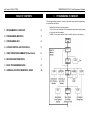
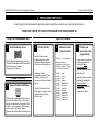
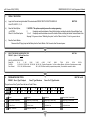
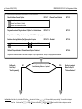
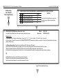
INNER RANGE IQ PLUS. Quick Programmer’s Manual.
Quick
Programmer’s Manual
© 2005. Inner Range Pty. Ltd.
Version 3.604 (31/03/05) p1
PLUS
Part Number: 630048plus
p2 Version 3.604 (31/03/05)
INNER RANGE IQ PLUS. Quick Programmer’s Manual.
TABLE OF CONTENTS.
1.
PROGRAMMING FLOWCHART.
The following flowchart provides an overview of the simple steps involved in programming
the system Data and Options.
1. PROGRAMMING FLOWCHART.
2
2. PROGRAMMING METHODS
3
3. PROGRAMMING KEY
4
4. ACCESS CONTROL AND THE IQPLUS
5
5. USER OPERATIONS SUMMARY (Default Users)
6
6. MASTER USER OPERATIONS.
7
7. BASIC PROGRAMMING GUIDE.
8
8. ADDRESS LOCATIONS NUMERICAL INDEX.
24
•
•
•
The Bold path indicates the typical sequence.
“<CLR>” can be used at anytime to Exit programming mode without saving changes
in the current data field displayed.
“<HOME>” can be used to clear the buffer of all data, ready for a new data entry.
Version 3.604 (31/03/05) p3
INNER RANGE IQ PLUS. Quick Programmer’s Manual.
2. PROGRAMMING METHODS
Inner Range IQ has been designed to provide a versatile system that is quick & easy to program & commission.
THERE ARE 5 WAYS TO QUICKLY PROGRAM YOUR INNER RANGE IQ.
FROM THE PROGRAMMING KEY
1
Portable Memory Device
Used to Download programming data into a
Controller that has been copied from another
Controller or from a Computer.
See page 4 of this manual.
FROM A COMPUTER
2
Upload / Download Software
Allows system programming while on-line to
the Controller or while off-line. Connection
can be via local Serial Port (using the “Port 0
Cable”) or via remote dial-up. This software
is also used to view “Review” history.
Download for free from www.innerrange.com
FROM THE TERMINAL
3
Factory Defaults
Much of the basic system
programming can be quickly
implemented by selecting one
of the System Default options.
See Page 16 of the
Programmer’s manual for the
Default procedure and an
overview of the System Default
options.
See the Tables section of the
Programmer’s manual for a full
description of each System
Default option.
4
Address Location
-Numerical Order
Section 9 - of the Programmer’s
Manual outlines the
programming of the IQ by the
numerical Address, a listing is
on Page 24 of this manual..
401-495
500-520
521-569
570-589
590-595
600-741
750-769
800-870
890-893
897-899
900-914
918-919
Users
Comms
Areas
Holidays
Daylight Saving
Zone Inputs
TimeZones
Auxiliaries
General Opts
System Inputs
Times/Counts
Access Control
5
Primary and
Secondary option
programming.
In many cases, a system can
be fully programmed by
following the Basic
Programming Guide
flowchart steps described on
pages 10 to 24.
Additional Features can then
be added by following the
Advanced Feature
Programming described in
Section 8 of the
Programmer’s Manual.
p4 Version 3.604 (31/03/05)
INNER RANGE IQ PLUS. Quick Programmer’s Manual.
3. PROGRAMMING KEY
3.1 INTRODUCTION.
THE PROGRAMMING KEY.
The IQ Programming Key is a portable non-volatile memory device housed in a convenient
“key tag”.
The Programming Key allows system programming to be uploaded from the Control
Module or downloaded to the Control Module by simply inserting the Programming Key
into Serial Port 0 and performing a simple key sequence on the LED Terminal. See below.
A built-in Lamp (embedded in the plastic surface) on the Programming Key visually
indicates when data transmission is active.
IQ PROGRAMMING KEY & FLASH INTERFACE.
This device allows the Programming Key to be connected to a PC for transferring Panel
data to and from the Upload/Download software.
NOTE: The IQ Programming Key & Flash Interface can also be used to connect a PC to
the “Flash” connector (JP8) on the Controller for the purpose of providing a Flash Upgrade
of the Controller Firmware version.
Refer to your Inner Range IQ distributor for more details.
3.2 IMPORT DATA FROM THE PROGRAMMING KEY.
This Mode allows the Installer to copy the programming contents of the Programming Key
into the Control Module.
IMPORTANT NOTE: The new data will override the existing contents of the Control
Module memory.
Connect the Programming Key to Serial Port 0 on the Control Module.
Select the Import Data Mode:
... , then
Enter PIN;
, then the Mode number;
,
,
.
The Lamp on the Programming Key will flash slowly to indicate data is being copied.
The Terminal beeper will sound 3 short beeps if the operation was successful, or 1 long
beep if unsuccessful.
3.3 EXPORT DATA TO THE PROGRAMMING KEY.
This Mode allows the Installer to copy the programming contents of the Control Module into
the Programming Key.
IMPORTANT NOTE: The Control Module data will override the existing contents of the
Programming Key.
Connect the Programming Key to Serial Port 0 on the Control Module.
Select the Export Data Mode:
Enter PIN;
... , then
, then the Mode number;
,
,
.
The Lamp on the Programming Key will flash quickly to indicate data is being copied.
The Terminal beeper will sound 3 short beeps if the operation was successful, or 1 long
beep if unsuccessful.
Version 3.604 (31/03/05) p5
INNER RANGE IQ PLUS. Quick Programmer’s Manual.
4. ACCESS CONTROL AND THE IQ PLUS.
REQUIRED EQUIPMENT.
Enhanced Access Terminal V2.01 or greater; Door strike; Relay board for door strike;
Wiegand reader. The Terminal installation document 635500EN contains additional information on installation.
DOOR OPTIONS.
The Door (door strike and door reed switch) connected to the Terminal is automatically
associated with that Terminal and can be referred to by the Terminal number, for example;
Terminal 1 = door 1. Terminals can be associated to areas and will only display zone activity
for that Area. (Address 561-564)
All doors will use the same global lock open time (time the door strike is activated) as
programmed at address 909 - Terminal Auxiliary time. This must be programmed to a value
other than 0 for the door to remain open following a valid request to open. If a 0 is left at
this location the lock will open but close again almost immediately, i.e. remain locked.
Valid entries are from 0 to 255 seconds. (Factory default 5 Seconds).
REQUEST TO EXIT BUTTON.
A “Request to Exit” (REX), is typically a button provided to unlock a door from the inside
either bypassing the need to use a reader during low security periods, or because an internal
(exit) reader is not required. The “REX” device can also be a PIR or Photo-Electric beam to
detect the User approaching the door. If a REX button is fitted it will activate the door for the
lock open time (see above). The REX operation is enabled regardless of the state of the
associated Area and is entered into Access Review.
The OFF key can also be used as a REX button if it is programmed at address 918.
ADDING A CARD AND USER PIN.
Once fitted and tested, learning the card (entering the card details into the panel) is done
exactly the same as adding a User PIN with the exception that the card is also presented
(explained in detail in Section 7, the Basic Programming Guide).
A User can have both a PIN and card, accessing the door using either method. A reader
need not be fitted if PIN only access is required. The door will open for lock open time
following a valid PIN + OFF key.
For higher security applications, both PIN and card can be required to open the door.
This option is global and is set at Address 919.
Each door will assume Area control of the Area associated with the Terminal, a Terminal
MUST be associated with an Area.
The following general rules apply: (see “Access Control” in Section 8)
1) If the User is assigned to an Area that is also associated to the Terminal,
(a)If the Area is armed, presenting a credential (card) will disarm the associated Area and
open the door. (The event is entered into Access Review).
(b) If the Area is disarmed, presenting a credential will open the door. (The event is
entered into Access Review)
2) If the User is not assigned to the Area associated to the Terminal,
(a) If the Area is armed, presenting a credential will not open the door (The event is entered
into Access Review).
(b) If the Area is disarmed, presenting a credential will open the door (The event is entered
into Access Review).
DOOR FORCED
A Door Forced condition is activated when the reed switch goes into alarm without a valid
request to open the door, this also causes the Door Forced system input to go into alarm.
(The event is entered into Access Review)
An Auxiliary can be used to indicate this system input by setting the Auxiliary type; 131
(door1) -138 (door 8) as described in the Tables-Section 10. This Auxiliary will pulse on for
500ms every 5 seconds till cleared. Door Forced is an Alarm condition and is cleared by
using a valid PIN+OFF key.
DOTL
A DOTL (Door open too long) condition is activated when the door is open for longer than a
period of time equal to 4 times that of the lock open time set at Address 909. This means
that once a valid request to open occurs, the lock timer starts and so does the DOTL timer.
Causing the DOTL system input to go into alarm. (The event is entered into Access Review)
An Auxiliary can be used to indicate this system input by setting the Auxiliary type; 141
(door 1) -148 (door 8) as described in the Tables-Section 10. This Auxiliary will pulse on for
500ms every 5 seconds till cleared. DOTL is a warning condition and is cleared by using a
valid PIN + OFF key or a valid card badge.
Door Forced and DOTL system inputs will turn on the fault light on the Terminal and LEDs
15 or 16 when a NEXT 13 is performed. (Refer System Inputs)
The Zones Inputs on terminals are used for door reed switch (zone1) and REX button
(zone2). Each zone must be fitted with the required device or, if not used, must be terminated with 6k8 resistors. These Zones cannot be used for security zones.
p6 Version 3.604 (31/03/05)
INNER RANGE IQ PLUS. Quick Programmer’s Manual.
5. USER OPERATIONS SUMMARY.
5.1
GENERAL USER OPERATIONS. (NO PIN CODE REQUIRED)
NEXT 11
Day Alarm On/Off.
This operation will toggle the Day Alarm function On and Off.
NEXT 12
Alarm History.
Any Zone Inputs that had an alarm during the last Arming period will be displayed on the Zone Lamps.
NEXT 13
Fault History.
Any System Inputs that had an alarm during the last 5 Arming periods will be displayed on the Zone Lamps. Flashing lamp indicates Input is currently in alarm.
Refer to the “System Inputs” table in the Programmer’s Manual for details.
NEXT 14
Zone Self Test History.
Any Zone Inputs that have failed the Zone Self Test will be displayed on the Zone Lamps.
NEXT 15
Display Firmware Version.
The 4 digits of the current Controller Firmware Version will be displayed in sequence. e.g. Sequence 3, 0, 0, 0, = V3.000.
NEXT 16
Display Door Alarm History.
Any Door Forced or DOTL Alarm dring the last 5 Arming periods will be displayed on the Zone lamps.
NEXT 19
Display Module Present.
Any Module present displayed on the LED display. For example “Terminal 1” present, LED 1 illuminated
5.2
USER OPERATIONS REQUIRING PIN CODE ACCESS. (Installer, Master and Arm/Disarm/Isolate User Types ONLY)
NEXT 21
Isolate / De-Isolate Zone Inputs.
Zone Lamps indicate Zones that are currently Isolated.
Entering the Zone number followed by
will toggle the Zone Isolated and De-Isolated.
Zones can be isolated by any User that has disarm permission for all the Areas that are assigned to the Zone.
System Inputs can be isolated by any User with permission to disarm.
NEXT 22
Isolate / De-Isolate System Alarms.
Zone Lamps indicate System Inputs that are currently Isolated.
Entering the System Input number followed by
will toggle the Input Isolated and De-Isolated.
Version 3.604 (31/03/05) p7
INNER RANGE IQ PLUS. Quick Programmer’s Manual.
NEXT 23
Activate Walk Test.
Puts the system into Walk Test Mode. Any Zone activation causes Siren squawk and Zone Lamp to flash. Press <CLR> to exit.
The system will automatically exit from Walk Test if the “Walk Test Time” (Address 912) expires.
Walk Test only monitors for the Seal and Alarm (Un-seal) conditions. No indication of Zone Input Tamper state is provided.
NEXT 24
Auxiliary Control and Test.
Auxiliary number followed by
0
= Siren Speaker output.
1
= Aux 1 (Strobe output)
will toggle the Auxiliary Output On and Off.
3
= Aux 2 (Gen purpose Aux on Controller)
4 - 10 = Aux 4 to 10. (Gen purpose Auxiliaries on Expansion card)
NEXT 25
Trigger Test Report.
Triggers a Test Report to the Central Monitoring Station or the nominated “Domestic Dialer” Telephone.
NEXT 26
Activates the Battery Test.
Switches the Battery Charger Off for 5 seconds to test Battery voltage. 3 Beeps at end of Test = Battery OK. One long tone = Battery Voltage Low.
NEXT 27
Answer Call.
Causes the Controller to automatically answer the next incoming call and attempt to establish Upload/Download connection.
This operation will over-ride any other programming option that disables a remote Upload/Download connection.
Primary and Secondary Telephone Numbers.
View / Program the Primary and Secondary numbers. (Installer Only with Contact ID enabled (NEXT 505)).
NEXT 31
NEXT 32
5.3
Call Divert Telephone Numbers.
View / Program the Diver and Un-Divert numbers. The IQ will dial Call Divert when the system is fully armed and dial the Call Un-Divert number when
Disarmed.
DEFAULT USERS
User Number
D e s c r ip t i o n
User 1
Installer, C a n p e r f o r m a l l I n s t a l l e r o p e r a t i o n s , a n d a l l M a s t e r o p e r a t i o n s .
DEFAULT USERS
Factory Default PIN
2345 (or 234567)
User 2
M a s te r U s e r ( P r i m a r y M a s t e r ) , C a n p e r f o r m a l l t h e M a s t e r o p e r a t i o n s a n d h a s a c c e s s t o a l l A r e a s .
The Master operations include; Edit Users, Walk test Zones, Set Time & Date,
S iren/Strobe/Auxiliary Te s t i n g , F a u l t A n a l y s i s , V i e w S o f t w a r e V e r s i o n , Te s t B a t t e r y a n d D o o r B e ll
E nable/Disable.
The Master User can also perform all User operations. This includes Arming / Dis-arming the
s y s t e m , Is o la t i n g Z o n e s a n d V i e w h i s t o r y . T h e M a s t e r U s e r a u t o m a t i c a l l y h a s p e r m i s s i o n t o c o n t r o l
a ll the A r e a s , Z o n e s a n d A u x i l i a r y o u t p u t s i n t h e s y s t e m .
0123 (or 012345)
User 3 to 95
General Users ,(Can be programmed as a Master User (Secondary Master))
C a n p e r f o r m a v a r i e t y o f o p e r a t i o n s s u c h a s A r m i n g / D i s - a r m i n g , Is o l a t i n g Z o n e s a n d V i e w
History with various levels of functionality as defined by the User’s “User Type”.
None
User 96
Reserved for system functions
(e.g. Reporting Auto-arming etc.)
N o t a p p licable
p8 Version 3.604 (31/03/05)
INNER RANGE IQ PLUS. Quick Programmer’s Manual.
6. MASTER USER OPERATIONS.
6.1
MASTER USER OPERATIONS
NEXT 33
View and/or Set the Time and Date.
Current Time & Date will be displayed in the sequence: hh:mm:DD:MM:YY:d. (Hours, Minutes, Day, Month, Year, Day-of-week)
,
1)
Enter the Time data (hh:mm) then
2)
Enter the Date data (DD:MM:YY) then
.
3)
Enter the Day of Week (1=Sunday - 7=Saturday) then
.
NEXT 4xx
User Programming. Refer to the following pages for details.
Refer to the User’s Manual for more information on these functions.
Version 3.604 (31/03/05) p9
INNER RANGE IQ PLUS. Quick Programmer’s Manual.
7. BASIC PROGRAMMING GUIDE.
1 ZONE TO 16 ZONE BURGLARY ALARM SYSTEM.
The Programming Sequence beginning on the following page takes the Installer through the steps required to program a typical Burglary Alarm System.
Programming options for Multi-Area systems, Access Control and Off-site reporting are included.
In many cases system programming can be completed by following these steps.
Where more advanced programming is required, follow this Basic Programming Guide first, then refer to the programming procedures found in Section 8 of the
Programmer’s Manual .
IMPORTANT NOTES:
1)
It is highly recommended that the system is fully defaulted to the factory presets as described in Step 1 before the rest of the programming sequence is performed.
2)
In the database fields described, only the options relevant to basic system programming are shown.
In many cases other options are available. Simply ignore any options not listed. These are not relevant to basic programming and are explained in the appropriate
applications in Section 8 of the Programmer’s Manual
3)
Section 9 of the Programmer’s Manual can be referred to for extra details on any option when required.
INSTALLATION NOTES:
1)
If Siren and Strobe are to be used, it is recommended that:
•
An 8 Ohm Siren Speaker is connected between “DET+” and “SPK” on connector T5 as shown in the Installation guide. (Aux 0)
•
A 12V Strobe is connected as follows: Strobe + to “DET+”, Strobe - to “OUT 1” on connector T5 as shown in the Installation guide. (Aux 1)
If you prefer to progam the system by following the Address locations in numerical order, go to Section 9 of the Programmer’s Manual
How to Enter Data. Select Address: Key in the Installer PIN Code; Press
Enter Data:
Enter the new Data
then enter the 3 digit Address
.. (1-16 digits) OR Option/s to Select/De-select
(A1 to A3 Lamps will flash to prompt for each digit). The current Data will be displayed.
, then
.
NOTE:
clears the current field of all data or settings ready for new data.
p10 Version 3.604 (31/03/05)
INNER RANGE IQ PLUS. Quick Programmer’s Manual.
1.
DEFAULT THE SYSTEM.
a)
Logon to the Terminal using the Installer PIN code and select DEFAULTING THE CONTROL MODULE.
-Enter PIN, <NEXT>, 0, 9, 8.
b)
Select the Default Option.
- n, <ENTER>.
Where “n” is the Default option.
c)
Reset the Control Module.
Disconnect the AC Supply input and the Battery from the Control Module. Wait 5 seconds, then Re-connect power.
2.
SELECT THE END-OF-LINE RESISTOR TYPE.
DEFAULT: Option 3 - 3k3 Single End-of-Line.
NEXT 098
! CAUTION: This option completely erases all current programming.
0:
Completely resets the database to Factory Default settings, including the Installer Code and Master Code.
1, 2 or 3:
Completely resets the database to one of the Installer Presets, including the Installer Code and Master Code.
See page 16 Programmer’s Manual “Defaulting the system”, and the Tables in Section 10 of the Programmer’s Manual.
t
NEXT 600
END-OF-LINE RESISTOR TYPES:
Single EOL:
0 -1k
1 -1k5
2 -2k2
3 -3k3
4 -3k9
5 -4k7
6 -5k6
7 -6k8
8 -10k
9 -12k
10 -22k
Dual EOL:
11 -2k2, 2k2 12 -2k2, 6k8 13 -3k3, 6k8 14 -10k, 10k (Provides Tamper state. 1st Value is Series Resistor, 2nd Value is Resistor across contacts)
Zone Doubed:
15 -1k, 3k3, 6k8 Zone doubled
16 -1k, 3k3, 6k8 Zone doubled (no seperate tamper state) See installation manual for details.
3.
t
PROGRAM THE ZONE TYPE/S.
DEFAULT: Zone 1; Type 1-Delayed.
Zone 2; Type 2-Handover
NEXT 601 to 616
Zones 3 to 16; Type 0-Instant.
Program the new Zone Type for Zones that are not “Instant” Zones.
Zone
Address
1
2
3
4
5
6
7
8
9
10
11
12
13
14
15
16
601
602
603
604
605
606
607
608
609
610
611
612
613
614
615
616
Zone Types:
0
Instant
1
Delayed
2
Handover
3
Away Instant / Home Isolate
4
Away Instant / HomeDelay
5
Away Delay / Home Isolate
6
Away Delay / Home Delay
7
Away Delay / Home Instant
8
Away Handover / Home Isolate
9
Away Handover / Home Delay
10
24 Hour Burglary
11
24 Hour Fire
12
24 Hour Panic
13
24 Hour duress
14
KeySwitch Arm
15
KeySwitch Home
16
Delay / Force Arm
17
Handover / Force Arm
t
Version 3.604 (31/03/05) p11
INNER RANGE IQ PLUS. Quick Programmer’s Manual.
4.
PROGRAM ANY ADDITIONAL BASIC OPTIONS FOR ZONE INPUTS.
Zone
Address
NEXT 651 to 666
1
2
3
4
5
6
7
8
9
10
11
12
13
14
15
16
651
652
653
654
655
656
657
658
659
660
661
662
663
664
665
666
1
Silent
When selected, Siren is not activated when an alarm is triggered on this Zone. (NOTE: “Silent” over-rides “Siren Lockout”)
2
Siren Lockout
Zone will only trigger the Siren for the number of times specified in the “Siren Swinger Shutdown Count”. (Address 013)
7
Change Sense
(Normally Open Contacts)
The “Sealed” and “Alarm” states are swapped so that an alarm is triggered when an Open to Closed transition occurs on the detector contacts.
May be required for smoke detectors, etc.
t
5.
PROGRAM THE SIREN SWINGER SHUTDOWN COUNT.
DEFAULT: 16
(Only required if the “Siren Lockout” option is selected for any Zones in the Zone Options above)
NEXT 913
Program the number of times (0 to 255) the Siren can be triggered by a Zone Input in a single Arming period before Siren Lockout occurs.
(The counter is reset when the Area is turned Off)
6.
t
ENABLE/DISABLE THE SYSTEM INPUT ALARMS THAT ARE REQUIRED TO ACTIVATE THE SIREN.
1
AC Fail.
3
Cabinet Tamper. (Enabled by default)
5
Comms Fail / System Reset / Real-time Clock Problem.
2
Low Battery
4
Keypad Lockout.
6
Siren Monitor
NEXT 897.
7
LAN Fuse / Battery Fuse.
t
7.
ENABLE/DISABLE THE KEYPAD EMERGENCY ALARMS THAT ARE REQUIRED TO ACTIVATE THE SIREN.
1
Panic Alarms will activate the Siren.
Enabled by default
3
Fire Alarms will activate the Siren.
Enabled by default
5
Medical Alarms will activate the Siren.
Enabled by default
t
NEXT 899.
p12 Version 3.604 (31/03/05)
8.
INNER RANGE IQ PLUS. Quick Programmer’s Manual.
PROGRAM THE BASIC SYSTEM TIMERS.
HomeGuard Time.
DEFAULT: 90 Seconds.
NEXT 900
Program a value from 0 to 255 Seconds. Sets the Home Zone Entry Delay time for the “Home Delayed” function in Zone Types 4, 6 & 8.
Siren Time.
Program a value from 0 to 255 Minutes.
DEFAULT: 5 Minutes.
NEXT 904
Keypad Lockout Time.
DEFAULT: 5 Minutes.
NEXT 905
Program a value from 0 to 255 Seconds. Sets the time that keypad operation will be disabled after 5 incorrect login (PIN Code) attempts.
AC Report Delay Time.
DEFAULT: 0 Minutes.
NEXT 906
Program a value from 0 to 255 Minutes. Sets the time that the AC must be continuously disconnected before an AC Fail alarm is generated.
Siren Holdoff Time.
DEFAULT: 0 Seconds.
Program a value from 0 to 255 Seconds. Sets the time that the activation of the External Siren will be delayed after an alarm occurs.
NEXT 910
Fire Zone (Smoke Detector) Ignore Time.
DEFAULT: 60 Seconds.
NEXT 911
Program a value from 0 to 255 Seconds. Sets the time that activity on “24 Hour Fire” Zone Types will be ignored after a Smoke Detector Reset occurs.
t
9.
ENABLE/DISABLE ANY BASIC GENERAL SYSTEM OPTIONS THAT ARE REQUIRED FROM “GENERAL OPTIONS 1”.
NEXT 890
Option
Default
Description
1
2
3
Auto-Isolate on Arming.
Quick Arming.
Force Arm Areas.
No
No
No
4
5
Clock Synchronized to 50Hz AC Mains.
Zone Alarm indication after Disarm.
Yes
Yes
If selected, unsealed Zones will automatically isolate when the Area is Armed at the end of the Exit Delay.
If selected, no PIN Code required for arming Areas.
If selected, Area will Arm regardless of any unsealed Zones.
If “Auto-Isolate on Arming” is selected, any unsealed Zones will be Isolated. If not, unsealed Zones will go into alarm.
Only Disable if Mains supply frequency is not stable, or if Controller is only powered by a DC supply.
Terminal automatically goes to Alarm History Display when Disarmed if an Alarm has occurred in that Area.
6
7
Display Zone activity when Disarmed.
Special Siren Tone for System Inputs
Yes
Yes
8
Single Exit Beep in Home Mode.
Yes
Enables display of Zone activity via the Terminal Zone LED’s when Area/System is Disarmed.
Special Siren Tone used for System Inputs that are programmed to activate the Siren.
No = Normal Burglary Siren Tone. (Default setting)
Yes = 1 Sec bursts for 4.25 minutes unless cancelled by PIN Code.
If selected, Exit beeps are replaced with a single beep at start of Exit Delay when Armed in Home Mode.
How to Enter Data. Select Address: Key in the Installer PIN Code; Press
Enter Data:
Enter the new Data
then enter the 3 digit Address
.. (1-16 digits) OR Option/s to Select/De-select
(A1 to A3 Lamps will flash to prompt for each digit). The current Data will be displayed.
, then
.
NOTE:
clears the current field of all data or settings ready for new data.
Version 3.604 (31/03/05) p13
INNER RANGE IQ PLUS. Quick Programmer’s Manual.
t
10.
PROGRAM THE CURRENT TIME AND DATE. (Master User Operation)
NEXT 33
Set the Real-Time Clock.
The Time, Date and Day of Week are programmed in 3 separate fields in the following order: hh:mm (1st Field); DD:MM:YY (2nd Field); day (3rd Field)
i.e. Hour, Hour; Minute, Minute; Day, Day; Month, Month; Year, Year; Day Of Week: (Sunday=1, Monday=2, Tues=3, Wed=4, Thurs=5, Fri=6, Saturday=7)
Key in the data for the current Field, then press <ENTER> to save the data in the current Field and advance to the next Field.
e.g. 1) 07:24 AM, 5th June, 2003. Monday.
0, 7, 2, 4, <ENTER>; 0, 5, 0, 6, 0, 3, <ENTER>; 2, <ENTER>.
2) 05:15 PM, 20th September, 2004. Thursday.
1, 7, 1, 5, <ENTER>; 2, 0, 0, 9, 0, 4, <ENTER>; 5, <ENTER>.
t
11.
PROGRAM THE DAYLIGHT SAVING START AND END DATES.
NEXT 590 to 595
Address Parameter
Range
Default
Address Parameter
Range
Default
590
Daylight Saving Start Month
0 - 12
0
593
Daylight Saving End Month
0 - 12
0
591
Daylight Saving Start Week
1-5
5
594
Daylight Saving End Week
1-5
5
592
Daylight Saving Day-of-week In Start Week
1-7
1
595
Daylight Saving Day-of-week In End Week
1-7
1
1 - Sunday
12.
2 - Monday
3 - Tuesday
4 - Wedesday
5 - Thursday
ENABLE THE STROBE. (IF A STROBE IS CONNECTED TO “OUT1”)
6 - Friday
t
The Strobe output (OUT1) on the Controller is controlled by Auxiliary 1.
To enable the Strobe output, assign Event Type 1 - Burglary Alarm (Strobe), to Auxiliary 1 at Address 801.
t
7 - Saturday
NEXT 801
p14 Version 3.604 (31/03/05)
INNER RANGE IQ PLUS. Quick Programmer’s Manual.
Single Area System.
Go to Step 14a.
Is the system a Multi-Area system?
NO
13.
14A. ASSIGN AREA 1 TO ALL ZONES USED.
DEFAULT: Area 1 assigned to Zones 1 to 8.
Address
Zone
Address
1
2
3
4
5
6
7
8
701
702
703
704
705
706
707
708
9
10
11
12
13
14
15
16
709
710
711
712
713
714
715
716
Multi Area System.
PROGRAM THE MULTI-AREA GENERAL OPTIONS.
NEXT 891
Option
Default
1
Multi Area system.
No
4
All Areas Siren Off control. No
Description
Any User with Disarm
privileges can cancel Siren.
t
NEXT 701 to 716
14B. ASSIGN THE REQUIRED AREA/S TO ZONES.
NEXT 701 to 716
DEFAULT: Area 1 assigned to Zones 1 to 8.
Assign Area 1 to all the Zones that are used in the system by enabling
Option 1 (Area 1) in the relevant Addresses from 701 to 716.
Zone
YES.
Assign the required Area/s to all the Zones that are used in the system by
enabling the Options in the relevant Addresses from 701 to 716.
NOTE: Normally, only one Area is assigned to a Zone.
Zone
Address
Zone
t
Address
1
2
3
4
5
6
7
8
701
702
703
704
705
706
707
708
9
10
11
12
13
14
15
16
709
710
711
712
713
714
715
716
1 - Area 1 assigned.
2 - Area 2 assigned.
3 - Area 3 assigned.
4 - Area 4 assigned.
t
How to Enter Data. Select Address: Key in the Installer PIN Code; Press
Enter Data:
Enter the new Data
then enter the 3 digit Address
.. (1-16 digits) OR Option/s to Select/De-select
(A1 to A3 Lamps will flash to prompt for each digit). The current Data will be displayed.
, then
.
NOTE:
clears the current field of all data or settings ready for new data.
Version 3.604 (31/03/05) p15
INNER RANGE IQ PLUS. Quick Programmer’s Manual.
Single Area System
Multi-Area System
15A. PROGRAM AREA 1 ENTRY DELAY.
DEFAULT: 30 Seconds
Program a value from 0 to 255 Seconds.
NEXT 531
PROGRAM AREA 1 EXIT DELAY.
DEFAULT: 60 Seconds
Program a value from 0 to 255 Seconds.
NEXT 541
15B. PROGRAM AREA ENTRY DELAYS AS REQUIRED.
DEFAULT: 30 Seconds
Area 1 ................................................................... NEXT 531
Area 2 ................................................................... NEXT 532
Area 3 ................................................................... NEXT 533
Area 4 ................................................................... NEXT 534
Program a value from 0 to 255 Seconds.
PROGRAM AREA EXIT DELAYS AS REQUIRED.
DEFAULT: 60 Seconds
Area 1 ................................................................... NEXT 541
Area 2 ................................................................... NEXT 542
Area 3 ................................................................... NEXT 543
Area 4 ................................................................... NEXT 544
Program a value from 0 to 255 Seconds.
Go to Step 17.
t
t
16.
PROGRAM THE TERMINAL ASSOCIATED AREA/S.
Terminal 1 ............................................................ NEXT 561
Terminal 2 ............................................................ NEXT 562
Terminal 3 ............................................................ NEXT 563
Terminal 4 ............................................................ NEXT 564
This determines the Area used for Arming/Disarming operations, Zone Lamp
display and Entry/Exit warnings. One of the following options can be selected:
0
1
2
3
4
t
-
Multi-Area (All Areas are associated with the Terminal) DEFAULT.
Area 1 is associated with the Terminal.
Area 2 is associated with the Terminal.
Area 3 is associated with the Terminal.
Area 4 is associated with the Terminal.
t
p16 Version 3.604 (31/03/05)
17.
INNER RANGE IQ PLUS. Quick Programmer’s Manual.
ENABLE/DISABLE REMOTE CONNECT FOR UPLOAD/DOWNLOAD.
Select the Remote Connect Option.
0
Remote Connect not allowed.
1
Remote Connect Enabled. (Default)
2
Remote Connect Enabled with Callback.
Program the number of Rings to Answer - If Option 1 or 2 selected above.
DEFAULT: 1 - Remote Connect Enabled
NEXT 512
DEFAULT: 16
NEXT 513
Program the number of Rings. A value in the range of 3 to 16 Rings may be programmed.
Enable an Answering Machine (Fax) Bypass option if required.
DEFAULT: 0 - Disabled
0
Disabled.
2
Follow-on time = 30 Seconds.
1
Follow-on time = 10 Seconds.
3
Follow-on time = 60 Seconds.
NEXT 514
Callback Telephone Number - If Remote Connect Option 2 is selected.
NEXT 504
Program the Telephone number of the Remote Computer. Up to 16 digits allowed. See Step 18 for programming information.
t
No Reporting.
Go to Step 30
“User Programming”
Is the system required to Report to a
Central Monitoring Station or a Telephone?
NO
How to Enter Data. Select Address: Key in the Installer PIN Code; Press
Enter the new Data
Reporting is required.
Move on to Step 18
“Telephone Numbers”.
t
t
Enter Data:
YES.
then enter the 3 digit Address
.. (1-16 digits) OR Option/s to Select/De-select
(A1 to A3 Lamps will flash to prompt for each digit). The current Data will be displayed.
, then
.
NOTE:
clears the current field of all data or settings ready for new data.
Version 3.604 (31/03/05) p17
INNER RANGE IQ PLUS. Quick Programmer’s Manual.
No Reporting.
Go to Step 30.
“User Programming”
t
Contact ID or Domestic Dialer Reporting.
18.
PROGRAM THE PRIMARY AND SECONDARY TELEPHONE NUMBERS.
Primary Telephone Number.
Program the Primary Telephone number for Reporting.
NEXT 500
Up to 16 digits allowed.
Secondary Telephone Number.
If required, program a Secondary Telephone number for Reporting.
Programming Telephone number digits:
0 to 9 = 0 to 9
10 = *
11 = #
12 = 4 Second pause
Multi-digit numbers are entered by pressing the <OFF> key.
19.
NEXT 501
Up to 16 digits allowed.
e.g. To program a #, Press <OFF>, 1, 1.
t
SELECT THE REPORTING FORMAT.
NEXT 505
1
Contact ID.
Reports to a Central Monitoring Station in Contact ID format via the PSTN Line connection.
2
Domestic Dialer.
Reports to a private telephone with simple tone beeps via the PSTN Line connection.
3
CFSK
Not available in this version
Securitel
Reports Securitel via Port 0 or Port 1 (see Section 8 of Programming Manual)
Dual Reporting
Reports to both of the programmed telephone numbers in Contact ID and/or Domestic Dialer formats.
4
Note: If Dual Reporting is required, select Option 8 FIRST. Refer to Programming Advanced Features Section 8 and
Programming Reference, Section 9 of Programming Manual for further details.
t
Domestic
Dialer.
t
Go to
Step 21
Dialer
Options.
NO
t
Is the Reporting Format
- Option 1 - Contact ID enabled?
YES
Contact ID
Move on to
Step 20
Client Codes.
t
p18 Version 3.604 (31/03/05)
INNER RANGE IQ PLUS. Quick Programmer’s Manual.
No Reporting.
Go to Step 30
“User Programming”
Domestic Dialer.
Go to Step 21
“Dialer Options”
t
t
Contact ID.
Go to Step 20 Client Codes.
20.
PROGRAM THE AREA CLIENT CODE/S.
Area 1 / General Area ................................................................ NEXT 521
Area 2 ........................................................................................ NEXT 522
Area 3 ........................................................................................ NEXT 523
Area 4 ........................................................................................ NEXT 524
Program one or more 4 digit Client Codes. Default for Area 1 is 9999, all other Areas are
blank and will use the value from Area 1 or if required, a unique Client Code may be
programmed for each Area that is to Report. Client Code/s are provided by the Central
Monitoring Station. Program the Securitel “Hard ID” into the General Area / Area 1 Client Code,
STU or PANEL must be restarted if the value is changed.
t
t
21.
PROGRAM THE DIALER OPTIONS.
Option
Default
1
2
Alarms reported via Dialer.
Alarm Restores reported via Dialer.
Yes
Yes
3
Isolates reported via Dialer.
Yes
4
Report Open only after an alarm.
No
5
General Open/Close reporting.
No
6
7
All Area Opens/Closes reported via Dialer.
System Restores reported via Dialer.
No
No
22.
Note: When Securitel Reporting is used, the
selected events at 506 will be reported via
Securitel
t
PROGRAM THE GENERAL OPEN/CLOSE AREA LISTS.
Required only if Dialer Option 5 -“General Open/Close Reporting” selected above.
DEFAULT: Area 1.
NEXT 507
Assign the required Area/s to the General Open/Close Area List: (NOTE: Area 1 must be included in the list)
1 - Include Area 1. (Enabled by Default)
3 - Include Area 3.
2 - Include Area 2.
4 - Include Area 4.
t
t
How to Enter Data. Select Address: Key in the Installer PIN Code; Press
Enter Data:
NEXT 506
Enter the new Data
then enter the 3 digit Address
.. (1-16 digits) OR Option/s to Select/De-select
(A1 to A3 Lamps will flash to prompt for each digit). The current Data will be displayed.
, then
.
NOTE:
clears the current field of all data or settings ready for new data.
Version 3.604 (31/03/05) p19
INNER RANGE IQ PLUS. Quick Programmer’s Manual.
No Reporting.
Go to Step 30
“User Programming”
23.
t
PROGRAM THE MAXIMUM DIAL ATTEMPTS.
DEFAULT: 8 Attempts
NEXT 508
Program the Maximum number of Dial Attempts from 1 to 16.
! CAUTION: Communications Authority Regulations limit the maximum number of dial attempts.
In Australia the ACA specify a limit of 10 Attempts.
t
24.
PROGRAM THE TEST REPORT OPTIONS.
Test Report Period
DEFAULT: 7
Program the number of Days between Test Reports from 0 (No Test Report) to 255.
NEXT 509
Program the Time of Day when the Test Report will be transmitted.
Test Report Hour
DEFAULT: 3
Program the Hour value from 0 to 23.
Test Report Minute
Program the Minute value from 0 to 59.
NEXT 510
DEFAULT: 30
NEXT 511
t
25.
PROGRAM THE DIALER LOCKOUT OPTION FOR ZONE INPUTS IF REQUIRED.
Zone
Address
3
t
NEXT 651 to 666
1
2
3
4
5
6
7
8
9
10
11
12
13
14
15
16
651
652
653
654
655
656
657
658
659
660
661
662
663
664
665
666
Dialer Lockout
Zone will only trigger the Dialer for the number of times specified in the “Dialer Swinger Shutdown Count”.
(Address 014)
t
p20 Version 3.604 (31/03/05)
No Reporting.
Go to Step 30
“User Programming”
t
INNER RANGE IQ PLUS. Quick Programmer’s Manual.
26.
PROGRAM THE DIALER SWINGER SHUTDOWN COUNT.
NEXT 914
DEFAULT: 16
(Only required if the “Dialer Lockout” option is selected for any Zones in the Zone Options in Step 25 above)
Program the number of times (0 to 255) the Dialer can be triggered by a Zone Input, in a single Arming period, before Siren
Lockout occurs.
(The counter is reset when the Area is turned Off)
t
27.
ENABLE/DISABLE ANY GENERAL OPTIONS THAT ARE REQUIRED FROM “GENERAL OPTIONS 2”.
NEXT 891
Option
Default
Description
6
Delay Siren until Comms complete.
No
8
Dialer enabled in Home Mode.
No
Siren operation will not be initiated until a report has been sucessfully
sent, or a Comms Fail alarm generated.
If selected, Alarms and Open/Close reports will be sent for Areas armed
in Home Mode.
t
28.
t
ENABLE/DISABLE THE SYSTEM INPUT ALARMS THAT ARE REQUIRED TO ACTIVATE THE DIALER.
NEXT 898.
Option
Default
1
2
3
AC Fail.
Low Battery.
Cabinet Tamper.
Yes
Yes
Yes
4
5
6
7
Keypad Lockout.
Comms Fail / System Reset.
Siren Monitor.
LAN Fuse / Battery Fuse.
No
Yes
Yes
Yes
8
Zone Self-Test Fail.
No
Default
Door Forced
NO
t
How to Enter Data. Select Address: Key in the Installer PIN Code; Press
Enter Data:
15
Option
Enter the new Data
then enter the 3 digit Address
.. (1-16 digits) OR Option/s to Select/De-select
(A1 to A3 Lamps will flash to prompt for each digit). The current Data will be displayed.
, then
.
NOTE:
clears the current field of all data or settings ready for new data.
Version 3.604 (31/03/05) p21
INNER RANGE IQ PLUS. Quick Programmer’s Manual.
No Reporting.
Go to Step 30
“User Programming”
t
t
30.
29.
ENABLE/DISABLE THE KEYPAD EMERGENCY ALARMS REQUIRED TO ACTIVATE THE DIALER.
NEXT 899.
Option
Default
2
Panic Alarms will activate the Dialer.
Yes
4
Fire Alarms will activate the Dialer.
Yes
Note: When Securitel Reporting is used, the
selected events at 899 will be reported via
6
Medical Alarms will activate the Dialer.
Yes
Securitel
7
Duress Alarms will activate the Dialer.
No
PROGRAM THE USERS (Wireless Remote Key + Card)
An Installer Code or Master User Code must be used to program the Users.
t
Master:
Other Users:
NEXT 402
NEXT 403 to 495
Program a User.
1) Key in your PIN, then Select the User Number. Press
,
,
,
.(402 = Master. 403 to 495 = User 3 to User 95),
a User can have a Wireless Remote and/or a PIN OR a Card and/or a PIN. A seperate User Number is required if a User has a Wireless Remote and a Card
(different PIN numbers).
2a) Wireless Remote Key (if Required, used with Enhanced RF Terminals or RF Module)
Enrol the User Wireless Remote Key by pressing a button on the Remote Key within 30 seconds of selecting the User number.
Three short beeps will sound to confirm that the Remote Key has been enrolled and assigned to the selected User.
If the Remote Key is already assigned to another User, or is not recognised by the system, one long beep will sound to indicate a problem.
OR
2b) User Card (if required, used with Enhanced Access Terminals)
Present the card at the attached reader head and observe the tones.
High tones indicate acceptance, low tone indicate rejection of the card.
Step 30 Continued Next Page
t
p22 Version 3.604 (31/03/05)
30.
INNER RANGE IQ PLUS. Quick Programmer’s Manual.
PROGRAM THE USERS (Wireless Remote Key + Card) cont.
3) User PIN number (if required, must be entered if a Remote or Card is not used)
Enter the new PIN number
... (4 or 6 digits), then press
.
for each Area to be Assigned to this User (0=All Areas De-selected), then press
4) Press the Area number/s
5) Select the new User Type number
, then press
. See table below..
0
Arm Only.
1
Patrol. Arm / Disarm only after an alarm.
2
5
8
Arm / Disarm.
Toggle User Auxiliary B
Access Only
3
6
9
Defer Arm Only.
Arm / Disarm / Isolate.
Access Without Disarm
Delete a User.
1) Key in your PIN, then Select the User Number. Press
then
.
2) Press
,
,
,
4
7
.
Toggle User Auxiliary A
Master.
.
t
NO
Are the Access Control Options
REX, Door Forced, DOTL used?
YES
Move on to
Step 31
REX Button on Terminal.
Go to
Step 34
Change
Installer
PIN.
t
t
Version 3.604 (31/03/05) p23
INNER RANGE IQ PLUS. Quick Programmer’s Manual.
No Access Options.
Go to Step 34
“Change Installer PIN”
31.
t
REX BUTTON ON TERMINAL
An Installer Code or Master User Code must be used to program this option
,
,
,
, then
to enable (
1) Key in your PIN, then Press
This option enables the OFF key on the Terminal to act as a REX button
to disable ), default is disabled
t
32.
DOOR FORCED
An Installer Code or Master User Code must be used to program this option
Programming the DOOR FORCED system input for DOOR 1, to operate an auxiliary.
This option can require the use of the plug-on auxiliary board
1) Key in your PIN, then Press
,
,
,
, then
,
,
then
This assigns event type 131 to Aux 10, when the door reed for DOOR1 goes into alarm without a valid request to
open the door, an output on auxiliary 10 will occur. Cleared with a valid PIN + OFF key.
t
33.
DOOR OPEN TOO LONG (DOTL)
An Installer Code or Master User Code must be used to program this option
Programming the DOTL system input for DOOR 1, to operate an auxiliary.
This option can require the use of the plug-on auxiliary board
1) Key in your PIN, then Press
,
,
,
then
,
,
then
This assigns event type 141 to Aux 9, when the door reed for DOOR1 is open for longer than a period of time
equal to 4 times that of the lock open time set at address 909. Cleared with a valid PIN + OFF key or valid card badge.
t
t
p24 Version 3.604 (31/03/05)
INNER RANGE IQ PLUS. Quick Programmer’s Manual.
t
34.
t
CHANGE THE INSTALLER PIN CODE.
NEXT 401
This should be done before the system commissioning is completed and system operation is handed over to the client.
Ensure that a new PIN code is chosen that will not be forgotten, while still providing security against unauthorised access.
Follow the Steps of “Program a User” above. Note that Area Selection and User Type cannot be changed for the Installer Code.
The following features can be programmed to operate in addition to the Primary system features.
They can be found in the Programmer’s Manual.
Page in
Programmer's
Manual
Feature
Description
38
Access Control
Access Review to be written to General Review, Siren output when Door Forced alarm, Door Forced & DOTL reporting to the dialler.
39
Auto-Arm / Auto Disarm.
TimeZones can automatically Arm and/or Disarm Areas in Away or Home mode and provide auto-arm warnings if required.
40
Auxiliary to Follow a TimeZone
TimeZones can control Auxiliary outputs for automatic control of ancillary devices such as lighting, irrigation, pool filters, etc.
40
Battery Testing.
Automatic battery testing can be performed every 8 hours and/or on Area arming to ensure continuous operation if the AC power fails
41
Callback for Remote Connect.
Requirement for the system to callback a pre-programmed number to establish remote connection for Upload/Download.
41
41
Call Forwarding.
Computer connection (Local)
The system can dial your call divert number when armed and the un-divert number when disarmed.
A computer can be connected directly to the Controller via the on-board Serial Port for Upload/Download.
41
Computer Connection (Local) Printer
A printer can be directly connected to the Controller via the on-board Serial Port
42
Day Alarm.
A Zone Input can operate an Auxiliary output for activating Door Bells, lights, etc. when disarmed.
42
Defer Arming
Allows automatic arming if no movement is detected for a specified period to ensure thatat an Area is not left disarmed.
42
DTMF Remote Control
Remote Control of Areas and Auxiliaries can be provided from any touch-tone (DTMF) telephone.
42
43
Keyswitch Arming and Disarming.
Securitel Reporting Format
Keyswitches can be used to Arm and/or Disarm the system in addition to, or in place of, PIN Codes or Wireless Remote Keys.
Securitel Communications task and Reporting Format
44
Pulse Counting.
Provides more sophisticated monitoring of detection devices that require verification of an abnormal condition.
44
Siren output to operate as an Auxiliary.
The Siren Speaker output can be used as a normal Auxiliary output if required.
44
Six Digit PIN Codes.
Forces all PIN Codes programmed to be 6 digits in length for a higher level of User verification integrity.
44
Smoke Detector Reset
User PIN Code operation to momentarily activate an Auxiliary output to reset latching Smoke Detectors.
44
45
Sub Areas.
User Auxiliaries
Area 4 can be defined as a Sub-Area (or common Area) allowing it to be armed/disarmed by any, or all, of the other Areas.
PIN Codes can be programmed for the sole purpose of controlling one of 2 "User" Auxiliaries.
45
Walk Testing.
Allows Users to manually test detection devices.
46
Wireless Remote Control.
Wireless Remote Keys can be assigned to the system for Area control, Auxiliary control and Panic alarm.
46
Zone Self Testing.
Zones can be tested when the Area is disarmed to check for masking or other problems.
Version 3.604 (31/03/05) p25
INNER RANGE IQ PLUS. Quick Programmer’s Manual.
8. ADDRESS LOCATIONS NUMERICAL INDEX.
Address
Topic
Page in Programmer’s Manual
11
11 to 15
11 to 27
12
13
14
15
15
21
21 to 27
22
23
23
24
25
25
26
27
31
32
33
33
33
096
097
098
401 to 447
401 to 447
401 to 447
401 to 447
401 to 447
401 to 447
500
500 to 504
500 to 524
501
502
503
Day Alarm On/Off. ................................................................................ 17
General User Operations. .................................................................... 17
User Operations Summary. ................................................................. 18
Alarm History. ....................................................................................... 17
Fault History. ......................................................................................... 17
Zone Self Test History. ......................................................................... 17
Display Firmware Version. ................................................................... 17
Firmware Version. To Display. ............................................................ 17
Isolate / De-Isolate Zone Inputs. ......................................................... 17
User Operations Requiring PIN. .......................................................... 17-18
Isolate / De-Isolate System Alarms. .................................................... 17
Activate Walk Test. ............................................................................... 18
Walk Test. To Activate. ........................................................................ 18
Auxiliary Control and Test. ................................................................... 18
Test Report -To Trigger ........................................................................ 18
Trigger Test Report. .............................................................................. 18
Battery Test -Manual. ........................................................................... 18
Answer Call. ......................................................................................... 18
Primary and Secondary Telephone Numbers .................................... 18
Call Divert Telephone Numbers .......................................................... 18
Master User Operations & Summary .................................................. 18
Time and Date Programming - Basic .................................................. 25
Time and Date. View and/or Set ........................................................ 18
Import Data from the Programming Key ............................................. 10
Export Data to the Programming Key ................................................. 10
Defaulting the System .......................................................................... 16, 85
Adding Or Changing A User ................................................................ 19
Deleting A User ..................................................................................... 20
User Programming ............................................................................... 19
User Programming - Basic .................................................................. 33
User Programming. .............................................................................. 47
Users. Types. ....................................................................................... 6
Primary Telephone Number. ................................................................ 48
Telephone Number Programming. ...................................................... 47
Reporting Programming - Basic .......................................................... 29
Secondary Telephone Number. ........................................................... 48
Call Divert (Call Forwarding) Telephone No. ...................................... 48
Call Un-divert (Cancel Call Forwarding) Telephone No. .................... 48
504
505
505
505
505
505
506
506
506
506
506
506
507
507
508
508
509
509-511
510
511
512
512 to 514
512-514
513
514
515, 517
515,517
515-516
516, 518
521
521
521-524
522
523
524
531 to 534
531 to 564
541 to 544
551 to 554
551 to 554
559
560
Call-back Telephone Number .............................................................. 49
Contact ID Event Codes ...................................................................... 84
Contact ID Reporting Format .............................................................. 49
Domestic Dialer Reporting Format ...................................................... 49
Dual Reporting ..................................................................................... 49
Reporting Format ................................................................................. 49
Alarms are reported via Dialer. ............................................................ 50
Area Openings/Closings are reported via Dialer. ............................... 50
Dialler Options ...................................................................................... 50
Isolates are reported via Dialer. .......................................................... 50
Opening reports only sent after alarm has occurred. ........................ 50
Restores are reported via Dialer. ........................................................ 50
General Open/Close Area List ............................................................ 51
General Open/Close Reporting. .......................................................... 51
Dial Attempts. ....................................................................................... 51
Maximum Dial Attempts. ...................................................................... 51
Test Report Period ............................................................................... 52
Test Report ........................................................................................... 52
Test Report Hour .................................................................................. 52
Test Report Minute ............................................................................... 52
Remote Connect Method ..................................................................... 52
Remote Connect Programming - Basic .............................................. 28
Remote Connect Options .................................................................... 52
Rings To Answer ................................................................................... 53
Answer Machine (Fax) Bypass ............................................................ 53
Port 0/1 Comms Task ........................................................................... 53
Securitel Comms Task ......................................................................... 43
Serial Port Options ............................................................................... 53
Port 0/1 Baud Rate .............................................................................. 54
Area 1 (General Area) Client Code ..................................................... 54
General Area (Area 1) Client Code ..................................................... 54
Client Codes (Contact ID) .................................................................... 54
Area 2 Client Code ............................................................................... 54
Area 3 Client Code ............................................................................... 54
Area 4 Client Code ............................................................................... 54
Area Entry Delay Programming. ......................................................... 55
Area Programming - Basic .................................................................. 27
Area Exit Delay Programming. ............................................................ 55
Arming Options ..................................................................................... 57
Timezone Control ................................................................................. 55
Auto Disarming Options ....................................................................... 56
Auto-arm In Home Mode ..................................................................... 57
p26 Version 3.604 (31/03/05)
561
569
570
570
571
590
590
590
600
600
600
601
601
601
601
601
601
601
601
601
601
601
651
651
651
651
651
651
651
651
701
750
800
800
800
801
830
860
860
890
890
890
to 564
to 589
to 595
to 595
to 595
to
to
to
to
to
to
to
to
to
to
to
to
to
to
to
to
to
to
to
to
to
to
to
to
to
to
666
666
616
616
616
616
616
616
616
616
616
616
616
666
666
666
666
666
666
666
666
716
769
810
810
870
to 840
to 870
to 870
Terminal Associated Area .................................................................... 57
Multi Area Options ................................................................................ 58
Holiday Day .......................................................................................... 58
Holidays ................................................................................................ 58
Holiday Month ....................................................................................... 59
Daylight Saving .................................................................................... 59
Daylight Saving Programming - Basic ................................................ 25
Daylight Saving Time (DST) Start And End Dates ............................. 59
End-of-line Resistor Type .................................................................... 60
Zone Input Programming - Basic
22-23
Zone Input Programming - Basic ........................................................ 26
24 Hour Zone Types ............................................................................ 62
Delayed Zone Type .............................................................................. 61
Duress Zone Type ................................................................................ 62
Fire Zone Type ..................................................................................... 62
Handover Zone Type ........................................................................... 61
Home Zone Types ................................................................................ 61
Instant Zone Type................................................................................. 61
Key Switch Zone Types ....................................................................... 62
Panic Zone Type .................................................................................. 62
Zone Type ............................................................................................. 61
Zone Input Programming Overview .................................................... 60
Day Alarm Zone Option ....................................................................... 64
Dialer Lockout Zone Option ................................................................. 63
Normally Open (Change Sense) Zone Option ................................... 64
Pulse Count Zone Option .................................................................... 63
Self-Test Zone Option .......................................................................... 64
Silent Zone Option ............................................................................... 63
Siren Lockout Zone Option .................................................................. 63
Zone Options ........................................................................................ 64
Zone Areas ........................................................................................... 64
Timezones ............................................................................................ 65
Auxiliary Event Type ............................................................................. 66
Auxiliary Event Types ........................................................................... 66
Auxiliary Programming Overview ........................................................ 66
Strobe Programming - Basic ............................................................... 25
Auxiliary Timer Value ........................................................................... 67
Auxiliary Action ..................................................................................... 67
Auxiliary Actions ................................................................................... 82
Auto Isolate on Arming ......................................................................... 68
Clock synchronized to 50Hz AC Mains. .............................................. 68
Display Zone activity on Terminals. ..................................................... 68
INNER RANGE IQ PLUS. Quick Programmer’s Manual.
890
890
890
890
890
890
890
890
891
891
891
891
891
891
891
891
891
891
891
892
892
892
892
892
892
892
892
893
897
897
897
897
897
897 to 898
897 to 898
898
899
899
899
899
899
899
Force Arm Areas. ................................................................................. 68
General Option Programming - Basic ................................................. 24
General Options. 1. ............................................................................. 68
Quick Arming ........................................................................................ 68
Single Exit Beep in Home Mode. ........................................................ 68
Special Siren Tone for System Alarms. ............................................... 68
Zone activity on Terminals. To Display. .............................................. 68
Zone Alarm indication after Disarm. .................................................... 68
All Area Siren Off control. .................................................................... 69
Bell Squawk on Siren for Wireless Remote Key. ............................... 69
Call Forwarding. ................................................................................... 69
Day Alarms To Activate Terminal Beeper ............................................ 69
Delay Siren until Comms complete ..................................................... 69
Dialer enabled in Home Mode. ............................................................ 69
DTMF Control. ...................................................................................... 69
General Options. 2. ............................................................................. 69
Multi-Area System. ............................................................................... 69
Mutli-Area Option Programming - Basic ............................................. 26
Terminal Beeper for Day Alarms. ........................................................ 69
6 Digit PIN codes ................................................................................. 70
Automatic Battery Testing. ................................................................... 70
Battery Test on Arming. ........................................................................ 70
Battery Testing -Automatic. .................................................................. 70
General Options. 3. ............................................................................. 70
Keyswitch Zones Latching. .................................................................. 70
Pulse Count Handover. ........................................................................ 70
Siren Output To Operate As An Auxiliary ............................................ 70
General Options. 4. ............................................................................. 71
Fire alarms will activate the Siren. ...................................................... 71
Siren. Emergency Alarms to activate Siren. ...................................... 71
Siren. System Inputs to activate Siren. .............................................. 71
System Input Programming - Basic .................................................... 23
System Input Siren Enable .................................................................. 71
System Inputs ....................................................................................... 83
System Inputs Overview ...................................................................... 71
System Input Dialer Enable ................................................................. 72
Duress alarms will activate the Dialer. ................................................ 72
Duress Codes operation Enabled. ...................................................... 72
Emergency Alarm Programming - Basic ............................................ 23
Emergency Options ............................................................................. 72
Fire alarms will activate the Dialer. ..................................................... 72
Medical alarms will activate the Dialer. ............................................... 72
INNER RANGE IQ PLUS. Quick Programmer’s Manual.
899
899
899
900
900
900
900 to 911
901
902
903
904
905
906
907
908
909
910
911
912
913
913
914
914
918
919
Medical alarms will activate the Siren. ................................................ 72
Panic alarms will activate the Dialer. .................................................. 72
Panic alarms will activate the Siren. ................................................... 73
Counters ............................................................................................... 73
Homeguard Time .................................................................................. 73
Timers ................................................................................................... 73
Timer Programming - Basic ................................................................. 24
Pulse Count .......................................................................................... 73
Pulse Time ............................................................................................ 73
Zone Self-test Period ........................................................................... 73
Siren Time ............................................................................................. 73
Keypad Lockout Time .......................................................................... 74
AC Report Delay .................................................................................. 74
Auto-arm Pre-warn Time ...................................................................... 74
Re-auto-arm Time ................................................................................ 74
RF Terminal Auxiliary Time .................................................................. 75
Siren Hold-off Time .............................................................................. 75
24 Hr Fire Zone (Smoke Detector) Ignore Time ................................. 75
Walk Test Time ..................................................................................... 75
Siren Swinger Shutdown Count .......................................................... 76
Swinger Shutdown Count - Siren ........................................................ 76
Dialer Swinger Shutdown Count ......................................................... 76
Swinger Shutdown Count - Dialer ....................................................... 76
Access Options - REX ......................................................................... 76
Access Options - Card&Pin Door Control .......................................... 77
NOTE
The page numbers in the table above, refer to the Inner Range
IQ Plus Programmer’s Manual Part Number: 630047plus
Version 3.604 (31/03/05) p27
p28 Version 3.604 (31/03/05)
INNER RANGE IQ PLUS. Quick Programmer’s Manual.
Warranty
Inner Range Pty Ltd is proud of the reputation it has gained in the provision of high quality electronic products. Exhaustive factory and field testing ensure that enhanced system
programming features and additional hardware components operate as expected prior to their release to our customers. Extensive function testing is carried out on every Inner Range
product prior to it leaving the factory.
It is our intention to completely satisfy the requirements of our customers. To that end, Inner Range Pty Ltd stands behind its products with confidence. A Two Year Warranty accompanies
every Inner Range product. Should any Inner Range product fail to function as intended by the manufacturer within this period, it should be returned to the distributor and the fault or
symptom detailed. Inner Range will, at its own discretion, repair or replace the product as soon as possible.
This Warranty does not cover product failures occurring wholly or in part as a result of misuse, malicious damage, accidental damage or acts of nature.
Disclaimer
1)
The manufacturer and/or it’s agents take no responsibility for any damage, financial loss or injury caused to any equipment, property or persons resulting from the correct or incorrect
use of the Inner Range IQ system and its peripherals. The purchaser assumes all responsibility in the use of the IQ system and its peripherals.
2)
Whilst every effort has been made to ensure the accuracy of this manual, Inner Range Pty Ltd assumes no responsibility or liability for any errors or omissions. Due to ongoing
development the contents of this manual is subject to change without notice. Check regularly with your supplier or the Website for updates.