1
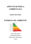
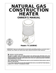
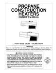
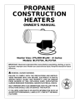
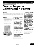
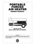
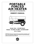
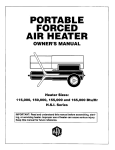
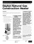
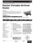
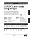
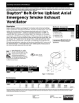
3VE56A
Operating Instructions & Parts Manual
Please read and save these instructions. Read carefully before attempting to assemble, install, operate or maintain the product described.
Protect yourself and others by observing all safety information. Failure to comply with instructions could result in personal injury and/or
property damage! Retain instructions for future reference.
Dayton Natural Gas
Construction Heater
®
Description
Dayton model 3VE56A is a natural gas fired construction heater, having a builtin thermostat, and a 150,000 BTU/Hr rating. The heater uses natural gas for combustion and electricity to operate the motor and fan. It is primarily to be used to
temporarily heat well-ventilated buildings under construction, alteration or repair.
This heater should be utilized in sheltered, well-ventilated areas, but never in
occupied dwellings.
Specifications
Figure 1 – Model 3VE56A
Model
Output Rating
BTU/Hr
Fuel
Fuel
Consumption
Hot Air Output
(CFM Approx)
Motor
Electric Motor
Input
Amperage
3VE56A
150,000
Natural Gas Only
150 Cubic Ft/Hr
435
3580 RPM
120V/60Hz, 1/9 HP
0.8
Model
Manifold
Pressure
Maximum Supply
Pressure to Heater
Minimum Supply
Pressure to Heater
Temperature
Control
3VE56A
3.3” W.C.
1/2 PSI
5” W.C.
Built-In Thermostat
Model
Ignition
3VE56A
Direct spark
Table of Contents
Page
Description ·····························1
Specifications ··························1
Unpacking ·····························1
General Safety Information ········1-3
Principals of Operation ···············3
Ventilation ····························3
Installation ·····························4
Operation ·····························4
Maintenance ························4-5
Storage ································5
Wiring Diagram ·······················6
Troubleshooting Chart ················7
Repair Parts Illustration ···············8
Repair Parts List ·······················9
Warranty ·····························12
Unpacking
1. Unpack all materials used to protect
the heater inside of carton. Retain
plastic caps attached to exposed
fittings for use during storage.
2. Remove heater, accessories and all
hardware from carton.
Form 5S4859
Weight
(Pounds)
Size
L x W x H (Inches)
24 (Heater)
35 (Shipping)
25.1 x 8.9 x 15.9
3. Inspect all items for damage that may
have occurred during shipment. If
there is any damage, promptly inform
the local Grainger branch where you
purchased heater.
General Safety Information
Make certain you read and understand
all warnings. Keep these instructions for
reference. They are your guide to safe
and proper operation of this heater.
Safety information appears throughout
these instructions. Pay close attention to
them. Below are definitions for the
safety information listed throughout
this manual.
Indicates an imminently hazardous
situation which, if not avoided, WILL
result in death or serious injury.
Indicates a potentially hazardous
situation which, if not avoided, MAY
result in minor or moderate injury.
IMPORTANT: Not every possible circumstance that might involve a hazard
can be anticipated. The warnings in this
manual and on tags or decals affixed to
the unit are therefore not all-inclusive.
If a procedure, work method, or operating technique not specifically recommended by Dayton is used, you must
make sure it is safe for you and others.
You should also ensure that equipment
will not be damaged or made unsafe by
the operating or maintenance method
you choose.
Consumer: Retain this manual for future
reference.
Indicates a potentially hazardous
situation which, if not avoided, COULD
result in death or serious injury.
Printed in Korea
09663
0605/263/VCPVP
PIN003
05/05
®
3VE56A
Dayton Operating Instructions and Parts Manual
Dayton Natural Gas Construction
Heater
®
General Safety Information
(Continued)
General Hazard
Warning: Failure
to comply with the precautions and
instructions provided with this heater
can result in death, serious bodily injury,
and property loss, or damage from
hazards of fire, explosion, burn, asphyxiation, carbon monoxide poisoning,
and/or electrical shock. Only persons
who can understand and follow these
instructions should use or service this
heater. If you need assistance or heater
information such as an instruction
manual, labels, etc. contact your local
Grainger branch.
Fire, burn, inhalation,
and explosion hazard.
Keep solid combustibles such as building materials, paper, or cardboard, at
a safe distance away from heater as
recommended by the instructions.
Never use the heater in spaces which
do or may contain volatile or airborne
combustibles or products such as
gasoline, solvents, paint thinner, dust
particles, or unknown chemicals.
Proposition 65
Warning: Fuels
used in gas, wood burning or oil-fired
appliances, and the products of combustion of such fuels, contain chemicals known to the State of California
to cause cancer, birth defects and
other reproductive harm.
Carbon monoxide
poisoning may lead
to death! Some people are more
affected by carbon monoxide than
others. Early signs of carbon monoxide
poisoning resemble the flu, with
headaches, dizziness, and/or nausea. If
you have these signs, the heater may
not be operating properly, or the areas
may not be sufficiently ventilated. Get
fresh air at once! Have heater serviced.
Natural Gas: Natural gas has a
distinctive odor. This odor helps you
detect a natural gas leak. However, the
odor may fade. Natural gas may be
present even though no odor exists.
Install and use heater
with care. Follow all
local ordinances and codes. In the
absence of local ordinances and codes,
refer to the National Fuel Gas Code
handbook NFPA54/ANSI Z223.1 and the
Natural Gas Installation Code, CAN/CGA
B149.1. This instructs on the safe
storage and handling of flammable
gases.
- Use only the electrical voltage and
frequency specified on model plate.
The electrical connections and
grounding of the heater shall follow
the National Electric Code, ANSI/NFPA
70 or the Canadian Electrical Code,
Part 1.
- Electrical grounding instructions - This
appliance is equipped with a threeprong (grounding) plug for your
protection against shock hazard and
should be plugged directly into a
properly grounded three-prong
receptacle or extension cord.
- Use only natural gas. Do not attempt
to operate on LP gas.
- Provide adequate ventilation. Before
using heater, provide at least a threesquare-foot opening of fresh, outside
air for each 100,000 Btu/Hr of rating.
This heater produces carbon monoxide, which is listed by the State of
California as a reproductive toxin
under Proposition 65.
2
- For indoor use only. Do not use heater
outdoors.
- Do not use heater in occupied
dwellings or in living or sleeping
quarters.
- Keep appliance area clear and free
from combustible materials, gasoline,
paint thinner, and other flammable
vapors and liquids. Dust is combustible. Do not use heater in areas with
high dust content.
Minimum heater clearances from
combustibles:
Outlet: 8 Ft
Sides: 2 Ft.
Top: 6 Ft.
Rear: 2 Ft.
- Check heater for damage before each
use. Do not use a damaged heater.
- Check hose (if used) before each use of
heater. If highly worn or cut, replace
with hose specified by manufacturer
before using heater.
- Locate heater on stable and level
surface if heater is hot or operating.
- Never block air inlet (rear) or air outlet
(front) of heater.
- Never operate heater while
unattended.
- Keep heater away from strong drafts,
wind, water spray, rain, or dripping
water.
- Keep children and animals away from
heater.
Dayton Operating Instructions and Parts Manual
Model 3VE56A
General Safety Information
(Continued)
Principals of Operation
TEMPERATURE CONTROL SYSTEM
FUEL SYSTEM
- This heater is equipped with a thermostat. Heater may start at anytime.
The pipe runs from the gas supply to
the heater itself. After the gas runs
through the pipe, it passes through
the solenoid valve and out the nozzle
into the combustion chamber.
A built-in thermostat allows the heater
to turn on and off to maintain a
consistent temperature.
- Never move, handle, or service a hot,
or operating heater. Severe burns may
result. You must wait 15 minutes after
turning heater off.
AIR SYSTEM
- To prevent injury, wear gloves when
handling heater.
The internal motor turns the fan, which
pushes air around and through the
combustion chamber. Here the air is
heated and provides a constant stream
of warmth.
- Never attach ductwork to heater.
- Do not alter heater. Keep heater in its
original state.
IGNITION SYSTEM
- Do not use heater if altered.
The spark module sends voltage to the
ignitor. The ignitor ignites the fuel and
air mixture.
- Turn off natural gas supply to heater
and unplug when not in use.
- Use only original replacement parts.
This heater must use design-specific
parts. Do not substitute or use generic
parts. Improper replacement parts
could cause serious or fatal injuries.
SAFETY CONTROL SYSTEM
This system shuts the heater down if the
flame is extinguished. The fan and
motor will continue to operate, but
there will not be any heat.
Ignitor
Nozzle
THE NATURAL GAS SUPPLY
The user of this heater must provide the
natural gas supply and all fittings to
properly install the heater.
The natural gas supply should be able
to provide a minimum of 150 cubic feet
of gas per hour for each heater being
used. Consult with your natural gas
supplier for the proper sizing of all gas
lines. You must regulate the natural gas
supply down from a minimum of 5
inches of water column to a maximum
of 1/2 PSI.
Be sure to research and follow all local
ordinances and codes. In the absence of
local codes, follow the National Fuel Gas
Code Handbook NFPA54/ANSI Z223.1
and the Natural Gas Installation Code,
CAN/CGA B149.1.
Ventilation
Fan
Motor
Guard
Clean
Heated
Air Out
(Front)
Power Cord
A three square foot
opening of fresh
outside air must be provided to operate
each heater safely. If the proper air
ventilation is not provided, carbon
monoxide poisoning can occur. Always
be sure that the proper ventilation is
being provided before starting this
heater.
On/Off Switch
Combustion Chamber
Solenoid Valve
Air Combustion
and Heating
PCB Control
Fuel
Regulator
Spark Module (Spark Ignitor)
Figure 2 – Cross Section Operational View
®
3
3VE56A
Dayton Operating Instructions and Parts Manual
Dayton Natural Gas Construction
Heater
®
Installation
Review and understand all of the
warnings in the Safety Information
Section on pages 1–3. They are required
to operate this heater safely. Follow all
local and state codes when operating
this heater.
Be sure to test all
connections for leaks
after installation or service. Never use
an open flame to check for leaks. Apply
a 50/50 mixture of dish soap and water
to each connection. If bubbles appear,
there is a leak. Correct all leaks
immediately.
1. Provide the natural gas supply system
(See Natural Gas Supply, on page 3).
2. Connect all plumbing and fittings to
the low-pressure Natural Gas source.
This source must be regulated to a
maximum of 1/2 PSI, and the piping
must be a 3/4 inside diameter
minimum, and not be over 10 feet
in length.
3. Line up the female threaded end of
the hose with the fitting on the
heater base and tighten.
4. Slowly open valve at natural gas
supply.
5. Check for leaks at all connections.
After installing all
gas piping, and
making the proper connections, be
sure to check for leaks. Apply a 50/50
mixture of dish soap and water to all
connections. Bubbles forming are
evidence of a leak. Be sure to correct
all leaks at once!
6. Close natural gas supply.
Operation
Review and understand all of the
warnings in the Safety Information
Section on pages 1–3. They are required
to operate this heater safely. Follow all
local and state codes when operating
this heater.
TO START HEATER
1. Follow all safety, installation and
ventilation instructions in this
manual.
2. Position the heater on a stable and
level surface, and be sure that no
drafts blow into the inlet or outlet of
the heater.
Inlet Connector
5. Open gas supply valve slowly.
6. Rotate on/off switch to the ON
position. Set thermostat to desired
temperature. Thermostat setting may
be too low if heater does not start.
Select a higher temperature to start
heater.
NOTE: If the heater does not ignite,
turn on/off switch to OFF position. Wait
for the safety control to reset (usually
about 10 seconds), and try again.
NOTE: If this does not work, the high
temperature switch may have opened
while the thermostat was shutting
down. Wait 10 to 15 minutes for the
switch to reset, then attempt to light
heater. Continued outages indicate a
system problem, have unit serviced
by a professional.
TO SHUT DOWN HEATER
1. Shut off the gas supply by closing the
valve tightly.
3. Plug the power cord of the heater
into a three prong grounded
extension cord. Be sure that the
extension cord is at least 6 feet long,
and is UL listed.
2. After a few seconds, the heater will
burn off the gas that was left in the
supply line.
EXTENSION CORD WIRE SIZE
REQUIREMENTS
4. Disconnect heater from power supply.
• Up to 50 feet long, use 18 AWG
rated cord.
Hose
4. Following the extension cord
requirements, plug the extension
cord into a 120 volt/60 Hertz, three
prong grounded outlet.
• 51 to 100 feet long, use 16 AWG
rated cord.
• 101 to 200 feet long, use 14 AWG
rated cord.
Figure 3 – Hose and Inlet Connector
4
3. Turn on/off switch to the OFF
position.
Maintenance
Do not attempt to
service the heater
while it is hot, operating or plugged
in. Severe burns or electrical shock
can occur.
1. Be sure to inspect the heater before
each use. Check for leaks using the
method described in Installation
section. Repair any leaks immediately.
Dayton Operating Instructions and Parts Manual
Model 3VE56A
Maintenance (Continued)
FAN
2. Always keep heater clean. Clean the
heater annually, or as often as
needed to remove any dust or debris.
When the heater becomes dirty, wipe
it down with a damp cloth.
IMPORTANT: Make sure not to bend
the fan blades when removing Guard
with Fan Motor Assembly from Heater.
This will help prevent damage to the
fan.
3. Keep the inside of the heater
free from foreign objects and
combustibles.
4. Have the heater inspected annually
by a qualified service person.
SERVICE PROCEDURES
Never service heater
while hot, operating
or connected to the gas supply. Severe
burns or electrical shock may occur.
REMOVING PROTECTIVE COVER
1. Remove base cover at the bottom of
the heater by removing two screws.
Guard (with Fan Motor Assembly)
Washer
Fan
Flange
Hex Nut
1. Remove base cover by removing two
screws.
Motor
2. Remove four screws from Guard.
3. Disconnect lead wires attached to
the motor from Plug Housing.
4. Remove Guard with Fan Motor
Assembly carefully.
5. Loosen fan setscrew using a 1/8” hex
wrench, and remove fan.
6. Using a soft cloth moistened with
kerosene or a cleaning solvent,
carefully clean the fan blades
making sure not to bend them.
Figure 5 – Fan Motor Shaft, Hex Nut
Location
IGNITOR
The only maintenance necessary for the
ignitor is to be sure that the gap
between the electrodes is kept between
.13” and .15”. The ignitor is accessible
through the combustion chamber.
Storage
Always disconnect
heater from gas
7. Dry fan with clean cloth.
supply.
8. Assemble fan on motor shaft and
tighten hex nuts firmly (be careful
not to overtighten).
1. Replace the plastic caps over the
fittings they were installed when you
originally unpacked your heater.
9. Reconnect lead wires as shown in
the Wiring Diagram (Figure 6).
2. Store the heater in a safe, clean and
dry location.
10. Reassemble guard and base cover.
3. When removing the heater from
storage, always check inside of the
heater for any foreign objects left by
spiders or small animals. Keep the
inside of the heater clean from
foreign objects and combustibles.
Base
Base Cover
Figure 4 – Protective Cover Removal
®
5
3VE56A
Dayton Operating Instructions and Parts Manual
Dayton Natural Gas Construction
Heater
®
Wiring Diagrams
Figure 6 – Wiring Diagram
6
3VE56A
Dayton Operating Instructions and Parts Manual
Dayton Natural Gas Construction
Heater
®
Troubleshooting Chart
Symptom
Possible Cause(s)
Corrective Action
Fan does not turn when
electrical connection is
made
1. No electric power to heater
1. Check current to electric outlet. If voltage is
correct, check power cord and extension cord for
cuts and breaks
2. Be sure that housing is not damaged. Make sure
there are no obstructions to the fan
3. Straighten blade(s) to match others
4. Replace motor
1. Check igniter wire. Reattach or tighten if loose.
Check spark module. Replace if necessary. Check
all electrical components
2. Set gap to 0.16”
3. Replace spark plug
4. Wait for five(5) minutes until limit switch returns
to a normal condition.
1. If the heaters output is restricted, internal temperature becomes too high. Move heater away
from any obstructions
2. Replace control valve
3. Clean inside of heater
2. Fan blade contacts inside of heater
housing
3. Fan blade(s) bent
4. Fan motor defective
Heater will not fire
1. No spark at igniter
Heater quits while
running
2. Improper spark gap
3. Bad electrode
4. Internal temperature too high causing
limit switch to shut down operation.
1. Internal temperature too high causing
limit switch to shut down operation
2. Damaged control valve
3. Dust or debris build-up inside of heater
Always be sure to follow proper maintenance procedures, by cleaning the heater once per month during regular
usage, and check spark gap at least once per season.
®
7
8
10
2
22
13
11
23
9
12
30
14
24
6
7
8
28
26
25
Figure 7 – Repair Parts Illustration for Natural Gas Construction Heater
Address parts correspondence to:
Grainger Parts
P.O. Box 3074
1657 Shermer Road
Northbrook, IL 60065-3074 U.S.A.
Please provide following information:
-Model number
-Serial number (if any)
-Part description and number as shown in parts list
24 hours a day – 365 days a year
27
15
29
For Repair Parts, call 1-800-323-0620
Dayton Operating Instructions and Parts Manual
1
4
3
31
16
5
32
17
36
35
20
34
18 19
33
21
3VE56A
3VE56A
Dayton Operating Instructions and Parts Manual
Models 3VE56A
Repair Parts List for Natural Gas Construction Heater
Reference
Number
Description
Part Number for Models:
3VE56A
1
2
3
4
5
6
7
8
9
10
11
12
13
14
15
16
17
18
19
20
21
22
23
24
25
26
27
28
29
30
31
32
33
34
35
36
Outer Shell
Inner Shell Ass’y
Base
Height Controller
Base Cover
Inner Shell Cap
MULTI BKT Ass’y
Thermal Swich
Tubing Ass’y
Main Nozzle Cap
Nozzle
Nozzle Nut
Sensor Plug BKT Ass’y
Sensor Cable
Thermal Switch Cable
Handle
Flange Hexa Nut
Fan
Cushion Pad
Motor Ass’y
Guard
Outlet Connector
Regulator
Middle Connector
Solenoid
Inlet Connector
Round Bolt
PCB
PCB Case
Solenoid Cable
Spark Module
Thermostat
Power Cord Ass’y
Thermostat Knob
Special Hexa Bolt
On-Off Switch
22-524-0010
22-524-0005
22-501-0005
22-512-0004
22-508-0004
22-505-0004
22-504-0004
22-603-0002
22-605-0004
22-505-0005
22-081-0005
22-518-0002
22-504-0005
22-601-0003
22-601-0002
22-511-0002
22-518-0003
22-514-0002
22-509-0001
22-061-0002
22-101-0004
22-507-0004
22-031-0001
22-507-0005
22-014-0001
22-507-0002
22-503-0003
22-521-0003
22-506-0002
22-601-0004
22-604-0002
22-012-0001
22-131-0002
22-516-0002
22-131-0001
22-603-0004
Quantity
1
1
1
1
1
1
1
1
1
1
1
1
1
1
1
1
1
1
1
1
1
1
1
1
1
1
1
1
1
1
1
1
1
1
2
1
®
9
3VE56A
Dayton Operating Instructions and Parts Manual
Notes
®
10
3VE56A
Dayton Operating Instructions and Parts Manual
Notes
®
11
Dayton Operating Instructions and Parts Manual
3VE56A
Dayton Natural Gas Construction
Heater
®
LIMITED WARRANTY
DAYTON ONE-YEAR LIMITED WARRANTY. Dayton® Natural Gas Construction Heater, Model covered in this manual, is
warranted by Dayton Electric Mfg. Co. (Dayton) to the original user against defects in workmanship or materials under
normal use for one year after date of purchase. Any part which is determined to be defective in material or workmanship
and returned to an authorized service location, as Dayton designates, shipping costs prepaid, will be, as the exclusive
remedy, repaired or replaced at Dayton’s option. For limited warranty claim procedures, see PROMPT DISPOSITION below.
This limited warranty gives purchasers specific legal rights which vary from jurisdiction to jurisdiction.
LIMITATION OF LIABILITY. To the extent allowable under applicable law, Dayton’s liability for consequential and incidental
damages is expressly disclaimed. Dayton’s liability in all events is limited to and shall not exceed the purchase price paid.
WARRANTY DISCLAIMER. Dayton has made a diligent effort to provide product information and illustrate the products in
this literature accurately; however, such information and illustrations are for the sole purpose of identification, and do not
express or imply a warranty that the products are MERCHANTABLE, or FIT FOR A PARTICULAR PURPOSE, or that the products
will necessarily conform to the illustrations or descriptions. Except as provided below, no warranty or affirmation of fact,
expressed or implied, other than as stated in the “LIMITED WARRANTY” above is made or authorized by Dayton.
PRODUCT SUITABILITY. Many jurisdictions have codes and regulations governing sales, construction, installation, and/or use
of products for certain purposes, which may vary from those in neighboring areas. While Dayton attempts to assure that its
products comply with such codes, it cannot guarantee compliance, and cannot be responsible for how the product is
installed or used. Before purchase and use of a product, review the product applications, and all applicable national and
local codes and regulations, and be sure that the product, installation, and use will comply with them.
Certain aspects of disclaimers are not applicable to consumer products; e.g., (a) some jurisdictions do not allow the exclusion
or limitation of incidental or consequential damages, so the above limitation or exclusion may not apply to you; (b) also,
some jurisdictions do not allow a limitation on how long an implied warranty lasts, consequentially the above limitation may
not apply to you; and (c) by law, during the period of this Limited Warranty, any implied warranties of implied merchantability or fitness for a particular purpose applicable to consumer products purchased by consumers, may not be excluded or
otherwise disclaimed.
PROMPT DISPOSITION. Dayton will make a good faith effort for prompt correction or other adjustment with respect to any
product which proves to be defective within limited warranty. For any product believed to be defective within limited
warranty, first write or call dealer from whom the product was purchased. Dealer will give additional directions. If unable to
resolve satisfactorily, write to Dayton at address below, giving dealer’s name, address, date, and number of dealer’s invoice,
and describing the nature of the defect. Title and risk of loss pass to buyer on delivery to common carrier. If product was
damaged in transit to you, file claim with carrier.
Manufactured for Dayton Electric Mfg. Co., 5959 W. Howard St., Niles, Illinois 60714 U.S.A.
Manufactured for Dayton Electric Mfg. Co.
Niles, Illinois 60714 U.S.A.
®