1
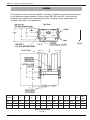
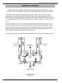
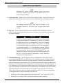
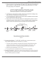
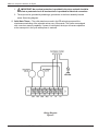
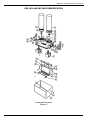
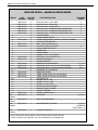
INSTRUCTION MANUAL FOR
WILKERSON MODELS DE0, DE1 AND DE2
COMPACT HEATLESS AIR DRYERS
DE0 - DE2
®
OPERATIONS
Wilkerson Compact Heatless Air Dryers
GENERAL
This instruction manual covers the installation, operation, maintenance and troubleshooting guide
for the Wilkerson compact heatless air dryers, models DE0, DE1 and DE2. These dryers are
designed to be installed into a compressed air system, providing ultra-dry compressed air to
continuous feed, point-of-use applications.
Top View
Outlet
D
C
A
B
Inlet
Front
E
Front View
A
L
M
K
G
F
H
J
Model
Number
G
H
J
K
L
M
Approx.
Wt.
(lbs.)
4.38
.25
.438 ± .016
8.125
7.219
6 3/4
A
B
C
D
E
DEO
10.875
4.0
2.72
1.50
1.82
DE1
13.875
7 3/4
DE2
16.875
8 3/4
F
3.375 ± .005 1.688 ± .016
Outline Dimensions
Figure 1
Instruction Manual / DE0, DE1 and DE2
Wilkerson Compact Heatless Air Dryers
DESCRIPTION OF OPERATION
Wilkerson DE series compact heatless air dryers employ the principles of pressure swing
adsorption (PSA). The operation is fully automatic and relatively little maintenance is required.
The dryers utilize two identical desiccant towers, metering orifices, two 3-way DC operated
solenoid valves controlled by a solid state electronic timer. Wet air at line pressure enters and
flows through one of the towers where nearly all the water vapor is adsorbed while the other tower
is being regenerated. Every 30 seconds, the process is reversed, providing a continuous flow of
dry air.
In the flow schematic shown below, Valve A (energized) directs the inlet air to flow into Tower A
(drying). A portion of the dry outlet air is allowed to flow through an orifice into Tower B. This dry
purge air expands to nearly atmospheric pressure, sweeping the water out of the desiccant as it
flows through Tower B (regenerating) and out of the Valve B (de-energized) exhaust port. The
timer controls the cycling of normally closed solenoid valves.
The orifices are fixed and are sized by the factory based on flow, pressure and dew point required.
DESICCANT
TOWER A
DESICCANT
TOWER B
DRY AIR
TO APPLICATION
PURGE
ORIFICE
PURGE
ORIFICE
A
B
CHECK
VALVES
SOLENOID
VALVE A
SOLENOID
VALVE B
PURGE AIR
EXHAUST
WET AIR IN
DEO, DE1 and DE2
Flow Schematic
Figure 2
Instruction Manual / DE0, DE1 and DE2
Wilkerson Compact Heatless Air Dryers
INSTALLATION AND OPERATION
NOTE
Wilkerson DE series compact heatless dryers have been
thoroughly inspected and tested at the factory and are in
proper working condition.
A. Initial Inspection – Remove the air dryer from the shipping carton. Inspect the exterior and
remove the electrical cover and inspect the interior components for any shipping damage.
NOTE
Any damage noticed at this time must be brought to the
immediate attention of the carrier and a freight claim must
be filed.
B. Warranty – Please read this instruction manual carefully before installing the air dryer.
Failure to follow proper instructions could result in damage to the equipment and may void
the product warranty.
!
CAUTION
!
EXCEPT as otherwise specified by the manufacturer, this product
is specifically designed for compressed air service and use with
any other gas or liquid is a misapplication. Use with or injection
of certain hazardous liquids or gases in the system (i.e., alcohol
or liquid petroleum gas) could be harmful to the unit and result in
a combustible condition or cause hazardous external leakage.
Manufacturers' warranties are void in the event of a misapplication
and manufacturer assumes NO RESPONSIBILITY for any
resulting loss. Before using equipment with fluids or gases other
than air, or for non-industrial applications, consult Wilkerson
Corporation for written approval.
C. Installation/Mounting – The DE series air dryers are designed for either wall or in-line
mounting. Models DE0, DE1, and DE2 allow for four alternate methods of piping. All dryers
require a clean ambient environment for proper operation. Normally, most locations where
ambient temperatures range between 40˚F and 125˚F are suitable for installation since drying
efficiency is more dependent on the temperature of the compressed air flowing through the
unit. Operating a unit at temperatures which could result in freezing may cause damage to the
dryer. Do not operate at temperatures so low that freezing is a possibility. The heat of internal
desiccant adsorption and normal solenoid valve operation may cause the unit to become
warm. This is normal and does not indicate a malfunction of the unit. The warm temperature
is more pronounced in a dryer operating at low flow rate.
1. Install dryer where ambient temperatures are between 40°F (4.4°C) and 125°F (52°C).
2. Mount dryer in a vertical position and with the desiccant towers at the top.
Instruction Manual / DE0, DE1 and DE2
Wilkerson Compact Heatless Air Dryers
3. Piping connections: For maximum flow, INLET and OUTLET piping should be schedule 40
pipe or equivalent I.D. tubing. DE0, DE1 and DE2 inlet and outlet porting is 1/4" female
NPT, purge porting is 1/8" female NPT.
NOTE
If purge air is required to be piped to a remote location, it is necessary to use slightly oversized tubing to prevent back-pressure.
Restricting the purge flow can cause the dryer to malfunction.
4. Use Teflon tape or pipe sealant on threads. Check all air connections for leakage, using
soap solution prior to putting dryer into permanent service.
5. It is recommended that a bypass line with shut-off valves be installed to provide constant
air flow, should the dryer require servicing.
6. Always install a 5-micron particulate prefilter and a coalescing filter upstream to remove
entrained particulates, moisture and oil. A 0.5-micron afterfilter should be installed downstream to remove any desiccant dust that may migrate from the desiccant towers.
BYPASS SHUT-OFF VALVE
BYPASS LINE
MOISTURE
INDICATOR
5-MICRON
PREFILTER
WITH AUTO
DRAIN
MICROALESCER
SHUT-OFF
VALVE
OPTIONAL
REGULATOR
AIR DRYER
WITH MOISTURE
INDICATOR
SHUT-OFF
VALVE
0.5-MICRON
POSTFILTER
OPTIONAL
REGULATOR
Factory Recommended Dryer Installation
Figure 3
D. Operating Specifications – The DE0, DE1, and DE2 series compact heatless dryers
can be sized to operate from 40 to 150 PSIG (2,7 to 10,3 bar).
1. The dryers must be operated in accordance with the factory sizing charts and original
customer requirements in order to achieve desired dewpoints. Inlet pressure, inlet
temperature, and outlet flow conditions are always specified when purchased.
2. Maximum inlet air temperature is 125°F (52°C).
3. Do not operate dryers in temperatures so low that freezing is a possibility.
E. Electrical Connections – Before wiring, check the dryer nameplate for electrical characteristics. Standard electrical characteristics are 115 Volt, 50/60Hz operation. Models operating on
230 Volt, 50/60Hz operation are available.
Instruction Manual / DE0, DE1 and DE2
Wilkerson Compact Heatless Air Dryers
1.
! IMPORTANT! No overload protection is provided in the dryer and unit should be
wired into a protected circuit. A knockout hole is provided for electrical connection.
2. The dryer can be grounded by attaching a ground wire to the timer assembly bracket
screw. See wiring diagram.
G. Solid State Timers – The solid state timers used in the DE series dryers permit the
simultaneous switching of the solenoid valves every 30 seconds. The timers are equipped
with a one hour memory capability. If power is interrupted, the dryer will resume operation
at the same point in the cycle when power is restored.
Wiring Diagram
Figure 4
Instruction Manual / DE0, DE1 and DE2
Wilkerson Compact Heatless Air Dryers
MAINTENANCE INSTRUCTIONS
A. Field Adjustments – Following proper installation of the Wilkerson DE heatless air dryer, no
field adjustments are necessary. No lubrication is required on the dryer.
B. Six-Month Check – It is recommended that every 6 months of operation, unit be thoroughly
inspected. Inspection should include audible inspection of the towers switching and purge flow.
Visual inspection should include checking for excessive dirt or oil fouling and for desiccant
attrition at the outlet and purge exhaust area. This involves removal of the manifold cover.
Remove mufflers, if installed, and check for excessive pressure drop by blowing through the
muffler. If large resistance is felt, mufflers should be replaced.
C. One-Year Check – Annual inspections should be more thorough and should include removal
of the solenoid valves and purge orifice glands for in-depth inspection of internal wear or deterioration of the solenoid valve parts, Viton check balls, and for plugging of the purge orifices.
D. Purge Orifices – If the operating conditions change from the label specifications (eg. inlet
pressure, outlet flow), it is necessary to replace the purge orifices. There are two orifices in the
DE series air dryers. The orifices are extremely critical parts in determining the performance of
the dryer and no attempt should be made to enlarge or reduce the hole size on the side of the
hex orifice gland. Orifices of the proper size must be obtained from your local Wilkerson
distributor. The label on the dryer should also be changed, noting the present operating
conditions. Purge orifices are screwed into the manifold beneath the desiccant chambers. To
change orifices, unscrew the hex orifice glands using a standard 7/8" socket wrench.
E. Cycle Timer – The solid state cycle timer requires no maintenance and can be replaced in
field.
F. Desiccant Towers – Improper packing of the desiccant chambers can cause channeling of the
air stream and improper drying. For this reason, NO ATTEMPT SHOULD BE MADE TO
REPACK DESICCANT CHAMBERS IN THE FIELD. Replacement chambers should be
obtained from your local Wilkerson distributor.
G. Operating Air Dryer Improperly – Following improper dryer operation, i.e., low inlet pressure,
high air temperature or high outlet flow, shut off the outlet flow from the air dryer for several
hours to allow the dryer to operate, purging the desiccant towers of excessive moisture. If this
does not restore dryer to proper working order, consult the troubleshooting guide at the end of
this instructional manual.
H. Oil Contamination – Oil contamination of the desiccant towers will cause complete loss of
drying capability. If oil is detected in the desiccant towers or any other components, it will be
necessary to install replacement towers in order to restore dryer to normal operation.
I.
Replacement Parts – Contact your local authorized Wilkerson distributor for dryers or replacement parts.
Instruction Manual / DE0, DE1 and DE2
Wilkerson Compact Heatless Air Dryers
IMPORTANT INFORMATION:
The installation of parts not supplied by
Wilkerson will void the warrant of our air dryers.
For replacement part information, contact Wilkerson Applications Engineering toll free at
1-888-223-5126.
Instruction Manual / DE0, DE1 and DE2
Wilkerson Compact Heatless Air Dryers
DE0, DE1 AND DE2 PARTS IDENTIFICATION
Parts Identification
Figure 5
Instruction Manual / DE0, DE1 and DE2
Wilkerson Compact Heatless Air Dryers
PARTS DESCRIPTION – WILKERSON HEATLESS DRYERS
ITEM NO.
PART
NUMBER
QTY. PER
DRYER
1
DRP-94-101
DRP-94-102
DRP-94-103
DRP-94-104
DRP-94-105
DRP-94-106
DRP-94-162
DRP-94-151
2
2
2
2
2
2
2
2
2
2
2
1
1
1
2
6
2
2
4
1
2
2
4
1
1
1
2
2
2
2
1
1
1
2
1
Desiccant Tower, 6" New, DE0
Desiccant Tower, 9" New, DE1
Desiccant Tower, 12" New, DE2
Desiccant Tower, 6" REPACK W/EXCHANGE, DE0
Desiccant Tower, 9" REPACK W/EXCHANGE, DE1
Desiccant Tower, 12" REPACK W/EXCHANGE, DE2
O-RING TOWER
O-RING, INNER ORIFICE
PURGE ORIFICE ASSY. (SPECIFY ORIFICE NUMBER)
O-RING, OUTER ORIFICE
BALL, VITON CHECK VALVE
HEX PLUG, INDICATOR PORT
O-RING, INDICATOR PORT
NAMEPLATE
DRIVE SCREW
SCREW, #10-24 X 5/8, PAN HD
PIPE PLUG, 1/4-18 SOCKET HD.
MOUNTING BRACKET
O-RING, BRACKET
MANIFOLD WITH BRACKETS
SOLENOID VALVE, 53 VDC (115 VAC DRYERS)
SOLENOID VALVE, 106 VDC (230 VAC DRYERS)
SCREW #6-32 X 3/8 PAN HD.
MANIFOLD COVER
TIMER, SOLID STATE (115 VAC DRYERS)
TIMER, SOLID STATE (230 VAC DRYERS)
NUT, KEPS 8-32
SCREW, 8-32 X 1" BH
SCREW, 8-32 X 1/4" BH
SCREW, 6-32 X 1/2" BH
PLATE, ADAPTER SS TIMER
BRACKET, MTG SS TIMER
COVER, TERMINAL
SPRING, CHECK VALVE
O-RING KIT
DRP-94-169
1
MOISTURE INDICATOR
DRP-94-173
1
MAINTENANCE KIT, DRYER
DRP-94-188
2
EXHAUST MUFFLER
2
3
4*
5
6
7
8
9
10
11
12
13
14
15
17
25
26
27
28
29
30
31
32
33
34
42
NOT
SHOWN
NOT
SHOWN
NOT
SHOWN
NOT
SHOWN
DRP-94-2XX
DRP-94-161
DRP-94-163
DRP-94-164
DRP-94-187
DRP-94-166
DRP-94-185
DRP-94-186
DRP-94-184
DRP-94-181
DRP-94-182
PART DESCRIPTION
When ordering parts, always state the dryer Model Number and Serial Number.
*Orifice number must be specified. This can be obtained from nameplate data.
Instruction Manual / DE0, DE1 and DE2
INCLUDES
ITEMS
2
2
2
2
2
2
3,5
8
11, 13, 14
36-41
36-41
2,3,5,8,14
2,3,5,6
17(REBUILD
PARTS ONLY), 42
Wilkerson Compact Heatless Air Dryers
MODELS DE0, DE1 AND DE2 TROUBLESHOOTING GUIDE
PROBLEM: AIR DRYER DELIVERS WET AIR
A
POSSIBLE CAUSE
CHECK
CORRECTIVE ACTION
A1
High inlet air temperature.
Inlet air temperature should not
exceed sizing criteria stated
at purchase (usually
70˚F or 100˚F).
Reduce inlet air temperature.
A2
Air demand in excess of rated
capacity of air dryer.
Check downstream flow demand
with flowmeter.
Reduce air usage downstream.
A3
Low inlet pressure.
Verify actual inlet pressure vs.
nameplate operating pressure.
Increase inlet pressure or call
factory to resize dryer for
inlet conditions.
A4
Dirty or obstructed inlet air
filter.
Check filter element.
Replace.
A5
Purge orifice plugged.
Remove and inspect purge orifice.
Clean hole of debris. Use air
gun to clean.
A6
Solenoid coil burned out.
Check magnetic field from coil
operation.
Remove cover, place iron or
steel material (screwdriver or
nail) on exposed end of solenoid
base to feel the magnetic effect,
indicating proper operation.
(Note: each coil should be
energized for 30 seconds).
A7
Oil contamination of
desiccant beds.
Verify particle/coalescing inlet
filtration is adequate and
functioning. Inspect inside of
desiccant towers for oily residue.
Towers must be replaced if
contamination is suspected.
A8
Timer not operating properly.
Check for proper voltage across
L2 and DC1 and across L2 and
DC2. Verify timing cycle is 30
seconds per side. Voltage should
read 53 volts DC on a 115 volt AC
unit or 106 volts DC on a 230 volt
AC unit.
Replace timer if voltage is
present at either DC terminal
continuously or not at all during
the 1 minute cycle -or- if wrong
voltage is measured.
A9
Purge flow restricted.
Check mufflers for excessive back
pressure.
Replace mufflers.
If purge air is piped away from
unit, oversized piping should be
used and length of run should be
as short as possible.
A10 Desiccant attrition
Remove the desiccant chambers
from the air manifold. Check if
perforated disc at open end of the
chambers can be depressed more
than 1/4" from the retaining ring.
Install new towers or have
towers repacked at the factory.
A11 Solenoid core spring broken.
Remove solenoid valve, inspect
core assembly.
Spring should be seated on core
and not broken. Replace if
necessary.
Instruction Manual / DE0, DE1 and DE2
Wilkerson Compact Heatless Air Dryers
MODELS DE0, DE1 AND DE2 TROUBLESHOOTING GUIDE
PROBLEM: RESTRICTED FLOW THROUGH UNIT
B
POSSIBLE CAUSE
CHECK
CORRECTIVE ACTION
B1 Incoming power interrupted.
Check the power supply. Measure
for voltage at the cycle timer.
If voltage is present, replace
timer.
B2 Improper operating conditions.
See A1, A2, A3 above.
B3 Dirty or obstructed inlet air
filter.
See A4 above.
B4 Improper plumbing.
Make sure inlet and outlet
connections are not reversed.
Correct plumbing.
B5 Plugged air passage.
Check inlet and outlet air
passages and piping for
blockages.
Clear restrictions.
B6 Solenoid coil burned out.
See A6 above.
B7 Timer not operating properly.
See A8 above.
B8 Solenoid core spring broken.
See A11 above.
Instruction Manual / DE0, DE1 and DE2
83-918-000 6/98


![Electrolux Lux 7000 Bagged Canister Vacuum - C:\Users\Jason&Kim\Desktop\Lux7000[1]](http://vs1.manualzilla.com/store/data/007257175_1-4f8df6fa53bec1c3cae9b6f5e2e6b2de-150x150.png)