1
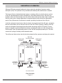
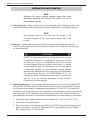
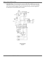
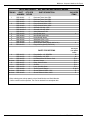
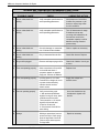
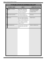
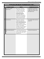
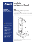
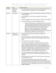
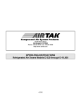
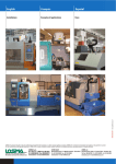
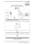
INSTRUCTION MANUAL FOR
WILKERSON MODELS DE3, DE4 AND DE5
COMPACT HEATLESS AIR DRYERS
DE3 - DE5
®
OPERATIONS
Wilkerson Compact Heatless Air Dryers
GENERAL
This instruction manual covers the installation, operation, maintenance and troubleshooting guide
for the Wilkerson compact heatless air dryers, models DE3, DE4 and DE5. These dryers are
designed to be installed into a compressed air system, providing ultra-dry compressed air to
moisture sensitive applications.
C
D
J
A
B
E
F
K
H
MUFFLERS
(OPTIONAL)
L
G
Outline Dimensions
Figure 1
Model
Number
A
B
C
D
E
F
G
H
J
K
L
DE3
DE4
35.50
35.50
34.50
34.50
16.00
16.00
8.00
8.00
6.50
6.50
1.50
1.50
17.00
17.00
8.50
8.50
3.63
3.63
4.13
4.13
5.63
5.63
DE5
41.00
39.50
18.62
9.31
6.50
1.50
20.13
10.06
6.75
4.75
6.38
Instruction Manual / DE3, DE4 and DE5
Wilkerson Compact Heatless Air Dryers
DESCRIPTION OF OPERATION
Wilkerson DE series compact heatless air dryers employ the principles of pressure swing
adsorption (PSA). The operation is fully automatic and relatively little maintenance is required.
The dryers utilize two identical desiccant towers, a metering orifice, two shuttle valves, and two
2-way AC operated solenoid valves controlled by a solid state electronic timer. Wet air at line
pressure enters and flows through one of the towers where nearly all the water vapor is adsorbed
while the other tower is being regenerated. A repressurization period follows the regeneration
period. Every 60 seconds, the process is reversed, providing a continuous flow of dry air.
In the flow schematic shown below, Valve A (closed, de-energized) and Valve B (open, energized)
allow the inlet shuttle valve to direct the inlet air to flow into Tower A (drying). A portion of the dry
outlet air is allowed to flow through the outlet shuttle valve purge orifice into Tower B. This dry
purge air expands to nearly atmospheric pressure, sweeping the water out of the desiccant as it
flows through Tower B (regenerating) and out of the Valve B (energized) exhaust port. The timer
controls the cycling of normally closed solenoid valves.
The orifices are fixed and are sized by the factory based on flow, pressure and dew point required.
DRY AIR
AIR
DRY
TO APPLICATION
DESICCANT
DESICCANT
TOWER
A
TOWER A
TO APPLICATION
DESICCANT
DESICCANT
TOWER B
TOWER B
OUTLET
OUTLET SHUTTLE
SHUTTLE
VALVE WITH
VALVE
WITH
PURGE ORIFICE
ORIFICE
PURGE
INLET
INLET
SHUTTLE
SHUTTLE
VALVE
VALVE
EXHAUST
EXHAUST
SOLENOID
SOLENOID
VALVE BB
VALVE
EXHAUST
EXHAUST
SOLENOID
SOLENOID
VALVE AA
VALVE
WET AIR
WET
AIRININ
PURGE
PURGE
AIR
AIR
EXHAUST
EXHAUST
DE3, DE4 and DE5
Flow Schematic
Figure 2
Instruction Manual / DE3, DE4 and DE5
Wilkerson Compact Heatless Air Dryers
INSTALLATION AND OPERATION
NOTE:
Wilkerson DE series compact heatless dryers have been
thoroughly inspected and tested at the factory and are in
proper working condition.
A. Initial Inspection – Remove the air dryer from the shipping carton. Inspect the exterior and
remove the electrical cover and inspect the interior components for any shipping damage.
NOTE:
Any damage noticed at this time must be brought to the
immediate attention of the carrier and a freight claim must
be filed.
B. Warranty – Please read this instruction manual carefully before installing the air dryer.
Failure to follow proper instructions could result in damage to the equipment and may void
the product warranty.
!
CAUTION:
!
EXCEPT as otherwise specified by the manufacturer, this product
is specifically designed for compressed air service and use with
any other gas or liquid is a misapplication. Use with or injection
of certain hazardous liquids or gases in the system (i.e., alcohol
or liquid petroleum gas) could be harmful to the unit and result in
a combustible condition or cause hazardous external leakage.
Manufacturers' warranties are void in the event of a misapplication
and manufacturer assumes NO RESPONSIBILITY for any
resulting loss. Before using equipment with fluids or gases other
than air, or for non-industrial applications, consult Wilkerson
Corporation for written approval.
C. Installation/Mounting – Four mounting holes are provided for wall mounting of Models DE3,
DE4 and DE5. All dryers require a clean ambient environment for proper operation. Normally,
most locations where ambient temperatures range between 40˚F and 125˚F are suitable for
installation since drying efficiency is more dependent on the temperature of the compressed air
flowing through the unit. Operating a unit at temperatures which could result in freezing may
cause damage to the dryer. Do not operate at temperatures so low that freezing is a possibility.
1. Install dryer where ambient temperatures are between 40°F (4.4°C) and 125°F (52°C).
2. Mount dryer in a vertical position.
3. Piping connections: For maximum flow, INLET and OUTLET piping should be schedule 40
pipe or equivalent I.D. tubing. DE3, DE4 and DE5 inlet and outlet ports are 1/2" female,
NPT, purge porting is 1/2" female, NPT.
Instruction Manual / DE3, DE4 and DE5
Wilkerson Compact Heatless Air Dryers
NOTE
If purge air is required to be piped to a remote location, it is
necessary to use oversized tubing to prevent back-pressure.
Restricting the purge flow can cause the dryer to malfunction.
4. Use Teflon tape or pipe sealant on threads. Check all air connections for leakage, using
soap solution prior to putting dryer into permanent service.
5. It is recommended that a bypass line with shut-off valves be installed to provide constant
air flow to the system, should the dryer require servicing.
6. Always install a 5-micron particulate prefilter and a coalescing filter upstream to remove
entrained particulates, moisture and oil. A 0.5-micron afterfilter should be installed downstream to remove any desiccant dust that may migrate from the desiccant towers.
BYPASS SHUT-OFF VALVE
BYPASS LINE
MOISTURE
INDICATOR
5-MICRON
PREFILTER
WITH AUTO
DRAIN
MICROALESCER
SHUT-OFF
VALVE
OPTIONAL
REGULATOR
AIR DRYER
WITH MOISTURE
INDICATOR
SHUT-OFF
VALVE
0.5-MICRON
POSTFILTER
OPTIONAL
REGULATOR
Factory Recommended Dryer Installation
Figure 3
D. Operating Specifications – The DE3, DE4 and DE5 series compact heatless dryers can
be sized to operate from 40 to 150 PSIG (2,7 to 10,3 bar).
1. The dryers must be operated in accordance with the factory sizing charts and original customer requirements in order to achieve desired dewpoints. Inlet pressure, inlet temperature, and outlet flow conditions are always specified when purchased.
2. Maximum inlet air temperature is 125°F (52°C).
3. Do not operate dryers in temperatures so low that freezing is a possibility.
E. Electrical Connections – Before wiring, check the dryer nameplate for electrical characteristics. Standard electrical characteristics are 115 Volt, 50/60Hz operation. Models operating on
230 Volt, 50/60Hz operation are available.
1.
! IMPORTANT! No overload protection is provided in the dryer and unit should be
wired into a protected circuit. A knockout hole with romex connector is provided for
electrical connection.
Instruction Manual / DE3, DE4 and DE5
Wilkerson Compact Heatless Air Dryers
F. Solid State Timers – The solid state timer used in the DE3, DE4 and DE5 dryers control the
switching of the solenoid valves during a two minute total time cycle. The timers are equipped
with a one hour memory capability. If power is interrupted, the dryer will resume operation at
the same point in the cycle when power is restored.
Wiring Diagram
Figure 4
Instruction Manual / DE3, DE4 and DE5
Wilkerson Compact Heatless Air Dryers
MAINTENANCE INSTRUCTIONS
A. Field Adjustments – Following proper installation of the Wilkerson DE heatless air dryer, no
field adjustments are necessary. No lubrication is required on the dryer.
B. Six-Month Check – It is recommended that every 6 months of operation, unit be thoroughly
inspected. Inspection should include audible inspection of the towers switching and purge flow.
Visual inspection should include checking for excessive dirt or oil fouling and for desiccant
attrition at the outlet and purge exhaust area. Remove mufflers, if installed, and check for
excessive pressure drop by blowing through the muffler. If large resistance is felt, mufflers
should be replaced.
C. Purge Orifice – If the operating conditions change from the label specifications (eg. inlet pressure, outlet flow), it is necessary to replace the purge orifice. There is one orifice in the DE3,
DE4 and DE5 air dryers. The orifice is an extremely critical part in determining the performance of the dryer and no attempt should be made to enlarge or reduce the hole size. An orifice of the proper size must be obtained from your local Wilkerson distributor. The label on the
dryer should also be changed, noting the present operating conditions. The purge orifice is
precision drilled in the outlet shuttle spool. To change the orifice, remove the three screws on
one side of the outlet shuttle valve. Remove and replace the orifice. Reassemble shuttle valve.
D. Cycle Timer – The solid state cycle timer requires no maintenance and can be replaced in
field.
E. Desiccant Towers – Desiccant towers are an all-welded design and are not repackable.
Replacement chambers should be obtained from your local Wilkerson distributor.
F. Operating Air Dryer Improperly – Following improper dryer operation, i.e., low inlet pressure,
high air temperature or high outlet flow, shut off the outlet flow from the air dryer for several
hours to allow the dryer to operate, purging the desiccant towers of excessive moisture. If this
does not restore dryer to proper working order, consult the troubleshooting guide.
G. Oil Contamination – Oil contamination of the desiccant towers will cause complete loss of
drying capability. If oil is detected in the desiccant towers or any other components, it will be
necessary to install replacement towers in order to restore dryer to normal operation. For this
reason, proper maintenance of the prefilters is essential.
H. Replacement Parts – Contact your local authorized Wilkerson distributor for dryers or replacement parts.
IMPORTANT INFORMATION
The installation of parts not supplied by
Wilkerson will void the warranty of our air dryers.
For replacement part information, contact Wilkerson Applications Engineering, toll free at
1-888-223-5126.
Instruction Manual / DE3, DE4 and DE5
Wilkerson Compact Heatless Air Dryers
DE3, DE4 and DE5 Parts Identification
7
,
8
11
10
6
1
12
13
2
5
3
,
4
Parts Identification
Figure 5
Instruction Manual / DE3, DE4 and DE5
9
Wilkerson Compact Heatless Air Dryers
PARTS DESCRIPTION – DE3, DE4 AND DE5 HEATLESS DRYERS
ITEM NO.
1
2
3
4
5
6
7
8*
9
10
not shown
11
12
not shown
13
not shown
not shown
PART
QTY. PER
NUMBER DRYER
DRP-94-301
DRP-94-302
DRP-94-303
DRP-94-399
DRP-94-400
DRP-94-321-2
DRP-94-322-2
DRP-94-311
DRP-94-393
DRP-94-600
DRP-94-374
DRP-94-335
DRP-94-336
DRP-94-394
DRP-94-6XX
DRP-94-371
DRP-94-372
DRP-94-375
DRP-94-376
DRP-94-377
DRP-94-378
DRP-94-379
DRP-94-380
DRP-94-399
DRP-94-400
2
2
2
2
2
2
2
2
1
1
1
1
1
1
1
2
2
1
1
1
1
1
2
1
1
PART DESCRIPTION
Desiccant Tower, New, DE3
Desiccant Tower, New, DE4
Desiccant Tower, New, DE5
Purge Solenoid Valve, 115V.
Purge Solenoid Valve, 230V.
Solenoid Coil Only, 115V.
Solenoid Coil Only, 230V.
Valve Maintenance Kit
Inlet Shuttle Valve
Inlet Shuttle Spool Only
Power On/Off Switch
Solid State Timer, 115V.
Solid State Timer, 230V.
Outlet Shuttle Valve (Specify Orifice No.)
Purge Orifice (Specify Orifice No.)
INCLUDES
ITEMS
4
8
PARTS FOR OPTIONS
For Dryers
with Option
Codes
Purge Muffler, 1/2", DE3/DE4
Purge Muffler, 3/4", DE5
Humidistat Board W/ Sensor Cord
Moisture Sensor
Relay, Shut-off Valve
Sonalert
Lamp, Humidity Alarm
Tower Pressure Gauge
Shut-off Solenoid Valve, 115V.
Shut-off Solenoid Valve, 230V.
M
M
E, H
E, H
E, H
E, H
E, H
E, H, P
E
E
When ordering parts, always state the dryer Model Number and Serial Number.
*Orifice number must be specified. This can be obtained from nameplate data.
Instruction Manual / DE3, DE4 and DE5
Wilkerson Compact Heatless Air Dryers
MODELS DE3, DE4 AND DE5 TROUBLESHOOTING GUIDE
PROBLEM: AIR DRYER DELIVERS WET AIR
A
POSSIBLE CAUSE
CHECK
CORRECTIVE ACTION
A1
No power to unit.
On/off switch or power supply.
Correct power problem.
A2
High inlet air temperature.
Inlet air temperature should not
exceed sizing criteria stated
at purchase (usually
70˚F or 100˚F).
Reduce inlet air temperature.
A3
Air demand in excess of rated
capacity of air dryer.
Check downstream flow demand
with flowmeter.
Reduce air usage downstream.
A4
Low inlet pressure.
Verify actual inlet pressure vs.
nameplate operating pressure.
Increase inlet pressure or call
factory to resize dryer for
inlet conditions.
A5
Dirty or obstructed inlet air filter. Check filter element.
Replace.
A6
Purge orifice plugged.
Remove and inspect purge orifice.
Clean hole of debris. Use air
gun to clean.
A7
Solenoid coil burned out.
Check magnetic field from coil
operation. Place iron or steel
material (screwdriver or nail) top
of coil to feel the magnetic effect,
indicating proper operation.
(Note: each coil should be
energized for 40 seconds every
other minute).
Replace.
A8
Oil contamination of
desiccant beds.
Verify particle/coalescing inlet
filtration is adequate and
functioning properly.
Towers must be replaced if
contamination is suspected.
A9
Timer not operating properly.
Verify correct timing cycle.
1. With terminals pulled back
slightly from lugs on timer, place
voltmeter across N and S1.
There should be a 115 volt AC
signal for 40 seconds and
0 volts for 80 seconds.
2. Check across N and S2 for
same timing.
At no time should there be
simultaneous signals at S1
and S2.
A10 Purge flow restricted.
Check mufflers for excessive back
pressure.
Instruction Manual / DE3, DE4 and DE5
Replace timer if defective.
Replace mufflers.
If purge air is piped away from
unit, oversized piping should be
used and length of run should be
as short as possible.
Wilkerson Compact Heatless Air Dryers
MODELS DE3, DE4 AND DE5 TROUBLESHOOTING GUIDE
B
PROBLEM: RESTRICTED FLOW THROUGH UNIT
POSSIBLE CAUSE
CHECK
B1
Improper operating conditions.
See A2, A3, A4 above.
B2
Dirty or obstructed inlet air
filter.
See A5 above.
B3
Plugged air passages.
Check inlet and outlet air
passages and piping for
blockages.
CORRECTIVE ACTION
Clear restrictions.
Instruction Manual / DE3, DE4 and DE5
Wilkerson Compact Heatless Air Dryers
MODELS DE3, DE4 AND DE5 TROUBLESHOOTING GUIDE
PROBLEM: EXCESSIVE PURGE / BLOWDOWN
C
POSSIBLE CAUSE
CHECK
CORRECTIVE ACTION
C1
Inlet or outlet shuttle not
shifting.
Verify nameplate specifications vs.
actual operating parameters.
Line pressure too low at inlet:
Increase line pressure or call
factory to resize purge orifice
for new conditions.
C2
Inlet or outlet shuttle not
shifting.
Verify nameplate specifications vs.
actual operating parameters.
Turn off downstream air usage.
If blowdown events stop
occurring, this indicates the air
flow was too much for the
compressor capacity or airline
diameter causing excessive
pressure drop.
C3
Inlet or outlet shuttle not
shifting.
Check for damage or contamination of inlet and outlet shuttles.
Clean or replace as necessary.
C4
Inlet or outlet shuttle not
shifting.
Dirty or obstructed inlet air filter.
Check filter element. Replace.
C5
Purge orifice plugged.
Remove and inspect purge orifice.
Clean hole of debris. Use air gun
to clean.
C6
Timer not operating properly.
Swith connections to S1 and S2
on the solid state timer. If
symptoms appear on opposite
purge port, the timer is defective.
Replace timer.
C7
Timer not operating properly.
Incoming power is not “clean.”
Fluctuations in voltage can occur
in power circuits shared by
inductive devices such as
electric motors.
Supply line voltage from
another source.
C8 Timer not operating properly.
Verify correct timing cycle.
1. With terminals pulled back
slightly from lugs on timer, place
voltmeter across N and S1.
There should be a 115 volt AC
signal for 40 seconds and
0 volts for 80 seconds.
2. Check across N and S2 for
same timing.
At no time should there be
simultaneous signals at S1
and S2.
C9 Leakage.
With dryer pressurized, remove
power form dryer. Check purge
ports for large leaks. Check all
joints on dryer and air system
for large leaks.
Repair as necessary.
Instruction Manual / DE3, DE4 and DE5
Wilkerson Compact Heatless Air Dryers
MODELS DE3, DE4 AND DE5 TROUBLESHOOTING GUIDE
D
PROBLEM: ALARM WILL NOT CLEAR
POSSIBLE CAUSE
CHECK
CORRECTIVE ACTION
D1
Wet air condition not corrected. See Section "A" of
Troubleshooting Guide.
D2
Sensor not dried out.
Allow several minutes for
sensor to dry out after correcting
dryer problem. Alarm should clear.
To speed up alarm clearing,
bleed some air through tire valve
at bottom of sensor housing.
Alarm should clear in less than
than 60 seconds.
D3
Bad humidistat board.
Disconnect humidity cable from
sensor. Alarm should clear.
Replace humidistat board.
Instruction Manual / DE3, DE4 and DE5
Wilkerson Compact Heatless Air Dryers
MODELS DE3, DE4 AND DE5 TROUBLESHOOTING GUIDE
PROBLEM: NO ALARM DURING WET AIR CONDITION
E
POSSIBLE CAUSE
CHECK
CORRECTIVE ACTION
E1
No power to humidistat
board.
With voltmeter, check for line
voltage at "Hot" and "Neutral"
terminals on humidistat board.
Also check for line voltage at
"Common" and "Neutral".
Make sure there is power to
dryer. Check wiring diagram
for correct wiring. Check
continuity of wires.
E2
Sensor cable connection.
Check cable connections at
sensor and at humidistat board.
Reconnect
E3
Bad sensor.
Remove air pressure from dryer.
With sensor cable connected and
power on, unscrew brass hex nut
at bottom of sensor housing. Blow
gently on sensor. The moist air
from your breath should cause
the alarm to sound.
Replace sensor.
E4
Bad humidistat board.
Press red "Push to Test" button on
humidistat board. Alarm should
sound.
Replace humidistat board.
Instruction Manual / DE3, DE4 and DE5
Wilkerson Compact Heatless Air Dryers
MODELS DE3, DE4 AND DE5 TROUBLESHOOTING GUIDE
PROBLEM: SHUTTLE VAL VE NOT FUNCTIONING PROPERLY
F
POSSIBLE CAUSE
CHECK
CORRECTIVE ACTION
F1
No power to shutoff
solenoid valve.
With power on, disconnect
humidity alarm sensor cable
from sensor. This will make
sure unit is not in alarm and
shutoff valve should be
energized. With voltmeter,
check for line voltage at
shutoff solenoid valve, wires
#15 and #16. If not reading line
voltage, check wires #17 and
#18, then wires #11 and #18.
If voltage at #17 and #18, and
voltage at #11 and #15, and no
voltage at #15 and #16, relay is
bad. Replace relay.
F2
Coil burned out.
With power on, disconnect
humidity sensor cable from
sensor. This will make sure unit
is not in alarm and shutoff valve
should be energized. Check
magnetic field from coil operation.
Hold iron or steel material
(screwdriver end or nail) at top of
coil to feel the magnetic effect,
indicating proper operation.
If no magnetic effect can be felt,
replace coil.
F3
Valve needs maintenance
kit.
If valve leaks with power off or if
causes F1 and F2 are eliminated,
you may need to install a valve
maintenance kit.
Install valve maintenance kit.
Instruction Manual / DE3, DE4 and DE5
Wilkerson Compact Heatless Air Dryers
Instruction Manual / DE3, DE4 and DE5
83-919-000-FL 6/98