1
TROUBLESHOOTING
FAN BLADE SETTING DIMENSIONS
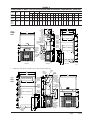
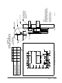
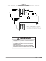
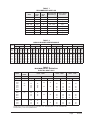
Shown in Figure 11 is the correct fan blade setting for
proper air delivery across the outdoor coil. Refer to
Table 1 for unit specific dimension.
Any service work requiring removal or adjustment
in the fan and/or motor area will require that the
dimensions below be checked and blade adjusted in or
out on the motor shaft accordingly.
FIGURE 11
FAN BLADE SETTING
R-410A
REFRIGERANT CHARGE
This unit was charged at the factory with the quantity of
refrigerant listed on the serial plate. AHRI capacity and
efficiency ratings were determined by testing with this
refrigerant charge quantity.
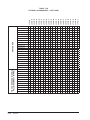
The following pressure tables show nominal pressures
for the units. Since many installation specific situations
can affect the pressure readings, this information should
only be used by certified technicians as a guide for
evaluating proper system performance. They shall not
be used to adjust charge. If charge is in doubt, reclaim,
evacuate and recharge the unit to the serial plate charge.
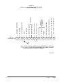
AIRFLOW
TABLE 2
REFRIGERANT CHARGE
Rated
Airflow
Model
"A"
MIS-1724
TABLE 1
FAN BLADE DIMENSION
Model
Dimension
A
J17A2 / J17L2
J24A2 / J24L2
1.00"
J30A2 / J30L2
J36A2 / J36L2
1.25"
J42A2 / J42L2
J48A2 / J48L2
J60A2 / J60L2
J70A2 / J70L2
1.75"
95°F OD
Temperature
82°F OD
Temperature
J24A2 / J24L2
800
56 - 60
56 - 60
J30A2 / J30L2
1000
57 - 61
57 - 61
J36A2 / J36L2
1100
56 - 60
57 - 61
J42A2 / J42L2
1400
58 - 62
60 - 64
J48A2 / J48L2
1550
63 - 67
65 - 69
J60A2 / J60L2
1650
63 - 67
64 - 68
The suction line temperatures in Table 4 above are
based upon 80°F dry bulb / 67°F wet bulb (50% R.H.)
temperature and rated airflow across the evaporator
during cooling cycle.
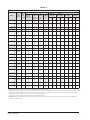
TABLE 3
REFRIGERANT CHARGE
Model
Rated
Airflow
95°F OD
Temperature
82°F OD
Temperature
REMOVAL OF FAN SHROUD
J17A1 / J17L1
550
18 - 21°
19 - 22°
1.Disconnect all power to the unit.
J70A1 / J70L1
1800
15 - 18°
16 - 19°
2.Remove the screws holding both grilles, one on
each side of unit, and remove grilles.
3.Remove screws holding fan shroud to condenser
and bottom. Nine (9) screws.
The correct system R-410A charge is shown on the unit
nameplate. Optimum unit performance will occur with
a refrigerant charge resulting in a liquid subcooling as
shown in Tables 2 & 3. If charge is in doubt, reclaim and
recharge to factory nameplate charge.
4.Unwire condenser fan motor.
5.Slide complete motor, fan blade, and shroud
assembly out the left side of the unit.
6.Service motor/fan as needed.
7.Reverse steps to reinstall.
Manual2100-588A
Page
21 of 29