1
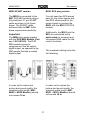
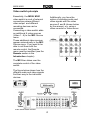
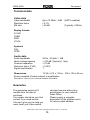
of t
of and
Re:connect
M300 / M301
Video switch
Dominating Entertainment.
Revox of Switzerland.
M300/ M301
Re:connect
Contents
Video switch
Installation
M300 - SCART
M301 – RCA plug
2
2
3
3
Video switch principle
Connection options
Connection format
Format ⇔ Quality
Video format
4
5
6
7
7
Monitor connection panel
SCART output features
Parallel operation
8
8
8
Video switch operation
Selecting the video source
Selecting the recording source
Free selection of listening source
Modifying source names
Edit function
Restoring standard names
9
9
9
10
10
11
13
Technical data
Guarantee
14
14
1
M300/ M301
Re:connect
Video switch
Installation
In order to be able to work
comfortably with the wealth of
multimedia devices that are
available, the video and audio
signals need to be controlled
intelligently. The M300 and
M301 Video switch from REVOX
offers you this comfort in some
impressive ways.
It can receive many different
video and audio signals and
then transmits them on to the
correct devices.
But it doesn’t just distribute
these signals, it also processes
them, using some incredibly
clean and powerful audio and
video drivers.
There are two versions of the
video switch, which are
differentiated from each other
by the connector panel that
connects the video switch with
the M51.
M300
The M300 has a single SCART
connector that handles the
complete communication with
the M51, including the video
and audio signals.
Correspondingly, you need the
DVD MKII module with the
SCART Connector (Part no.:
1.551.083.02) for the M300.
These high quality drivers are
even able to process the highresolution video format HDTV.
M301
The video switch is controlled
through the M51.
The M301 outputs the audio
and video signals through
individual RCA plugs.
Additionally, a patch cable (a
screened and uncrossed RJ45
cable) is needed for the control
functions.
Correspondingly, you need the
DVD MKII module with the
RCA connectors (Part no.:
1.551.083.03) for the M301.
2
M300/ M301
Re:connect
M300 SCART version
M301 RCA plug version
The M300 is connected to the
M51 DVD MKII module using a
fully switched, 21-pin SCART
cable as shown in the figure
below. The SCART cable
delivered with the M51 fulfils
these requirements perfectly.
You will need two RCA stereo
pairs for the video signals and
two RCA stereo pairs for the
audio signals to connect the
M301 with the M51 DVD RCA
module.
Additionally, the M301 and the
M51 are connected with a
patch cable (a screened and
uncrossed RJ45 cable) for the
control functions.
Important
The M300 only works together
with the DVD MKII Module (Part
no.: 1.551.083.02). The DVD
MKII module is easy to
recognise as it has an optical
digital output, as opposed to the
MKI module that has a coaxial
digital output.
The complete cabling locks like
the following:
In order not to reduce the
picture and sound quality, the
complete cable length (M51M301 + M301-Monitor) should
not exceed 10 m.
In order not to reduce the
picture and sound quality, the
complete cable length (M51M300 + M300-Monitor) should
not exceed 10 m.
3
M300/ M301
Re:connect
Video switch principle
Essentially, the M300/ M301
video switch is a set of external
connections where different
video output and different
recording devices can be
connected.
Connecting a video switch adds
an additional 6 video sources
(Video 1...6) to the M51 Source
menu.
These additional video sources
appear automatically in the M51
Source menu. If you want to be
able to call them with the
remote control, the Remote
menu must be modified (see the
Remote section in the
Introduction chapter).
Additionally; you have the
option of recording audio and
video signals with the video
sources 1 and 2 (shown below
by the arrows), e.g. using a
video recorder or video server.
The M51 then takes over the
complete control of the video
switch.
The figure below shows how the
different audio and video signals
find their way to the individual
devices.
Video switch basic function
4
M300/ M301
Re:connect
Connection options
The figure below gives you an
overview of the connection
options that the M300 and/ or
M301 offer.
In order to make this possible,
there must either be a SCART
connection to the television or
the TV audio output must be
connected to the Audio IN on
the monitor field on the
M300/M301 with a stereo RCA
cable.
The audio signal from the video
sources attached is transmitted
by the M51 whereas the picture
signal is handled by the video
devices attached, such as TV,
video projector, etc.
All other connections are made
as shown.
Additionally, the sound from the
TV can be put through the M51.
5
M300/ M301
Re:connect
Connection formats
In detail, the following
connections can be made with
the video sources 1 - 6:
Connection
Video 1
Video 2
Video 3
Video 4
Video 5
Video 6
Monitor
L
YC
CVBS
RGB
Y Cr Cb
=
=
=
=
Video Format
Input
Output
YC
YC
CVBS
CVBS
YC
YC
CVBS
CVBS
YC
CVBS
YC
CVBS
YC
CVBS
RGB
YCrCb
YC
CVBS
RGB
YCrCb
YC
CVBS
RGB
YCrCb
SCART
Audio Format
Input
Output
Analogue stereo Analogue stereo
Analogue stereo Analogue stereo
Analogue stereo Analogue stereo Analogue stereo
Digital stereo
Digital 5.1
(Coaxial)
Analogue stereo
Digital stereo
Digital 5.1
(Optical)
Analogue stereo Analogue stereo
S-VHS Signal
Normal video signal , also known as FBAS
Component signal with Red, Green, Blue
Colour difference signal, also shown with Y PR PB
You will find a more detailed description in the section Video mode in
the chapter DVD MKII-Module.
6
M300/ M301
Re:connect
Format ⇔ Quality
Video format
The quality of the picture
reproduction depends to a large
extent on the video format you
use.
Using the video switch, you
connect different video formats
to the inputs as well as the
monitor output.
The more parameters that affect
the picture, such as brightness,
colour and contrast, that are
grouped together, the worse the
quality of the picture will be. On
the other hand therefore, the
more parameters that can be
set individually, the better the
quality.
As we are dealing with a video
switch here, the video signals
are output in the same format
as they are fed in.
Example:
An RGB signal fed into the
Video 5 input will also be output
as an RGB signal to the monitor
output.
The following list gives you an
overview on this topic:
No conversion (Up- or DownMix) from one video format to
another video format is
carried out.
A Very good picture quality
RGB / YCrCb
3 component signal
YC Æ CVBS conversion
One exception to this is the YC
signal. This is the only signal
that is converted to the CVBS
format. In this way, it is possible
to feed in a YC signal through
the M51 or one of the six video
inputs (S-VHS) but to operate a
CVBS device at the monitor
output panel.
Additionally, this CVBS signal is
also available at the Video 1
and Video 2 outputs.
B Good picture quality
YC (S-VHS)
2 component signal
C Acceptable quality
CVBS (FBAS)
1 component signal
Important
It doesn’t improve the quality of
the picture if a YC or even an
RGB signal is artificially created
out of a CVBS signal. This
doesn’t increase the amount of
picture information, it simply
copies it.
7
M300/ M301
Re:connect
Monitor connection panel
SCART output features
The monitor connection panel is
set out the same for the M300
and the M301 versions of the
video switch.
If your device is fitted with a
SCART input, this is the
recommended connection to
use as you can also output a
6/12 voltage through the
SCART connector. This
switching voltage automatically
switches on the TV device with
the correct input, once an RGB
signal is present from the M51
or the Video 5 or Video 6
sources.
A pre-quirement for this is that
Video mode has been set to
RGB+CVBS through the DVD
MKII module set-up.
This switching voltage is part of
the SCART standard and for this
reason, it doesn’t work with the
YC or YCrCb signals.
This is where you connect the
devices that reproduce the
picture. This can be an LCD or
plasma screen or a normal
television.
Further, these outputs are also
available with projectors and
beamers of course.
Parallel operation
Internally, and at the monitor
panel, the video switch uses
exceptionally clean and
powerful video amplifiers. This
means that several monitors
can be operated in parallel at
different outputs without
impacting on the quality of the
picture.
In this way for example, the
television can be connected
through SCART while the
projector can be fed with a
signal from the YCrCb output.
The television sound from the
TV source can be put through
the M51 using the Audio-IN
socket.
With a SCART connection,
these audio signals are already
integrated.
8
M300/ M301
Re:connect
Video switch operation
Selecting the recording
source
Selecting the video source
The different sources are
selected through the SOURCE
menu. Press the Source button
on the M51 and the following
menu appears:
If you want to make a recording
using a device such as a video
recorder, for example, the M51
needs to know which source is
to be recorded from.
To do this, select the source as
described previously in the
Selecting the video source
chapter and then press the
Record softkey.
Now you can select the
individual Video and/or TV
sources by pressing the
corresponding softkey. Video 1
has been selected in the above
display as shown by the text:
Listening:
Video-1
Now, the music signal from the
selected source (e.g. Video-2,
DVD/CD, Aux2, etc.) will be
sent to the recording device
connected to the REC-OUT
RCA connector.
If the required source is not
shown on the first SOURCE
page, simply scroll to the next
page by pressing the More
softkey.
This will be shown in the display
by:
Recording:
Video-1
9
M300/ M301
Re:connect
Modifying source names
Free selection of the
listening source while
recording
The video switch offers you the
option of selecting your own
names for the inputs. You no
longer have to remember which
external device is connected to
which input. You can assign
names that tell you immediately
what is connected where.
The M51 also offers you the
option of listening to one source
at the same time as you record
another.
You could for example, be
recording a television
programme on a video server
through Video-1, while watching
a DVD at the same time.
You can enter a maximum of 8
characters as name text.
Select the video source whose
name you want to change
through the SOURCE menu.
This is possible with:
Video 1 to Video 6 and TV
To select a different source to
listen than the one you are
recording, simply select the
listening source through the
SOURCE menu, once you have
selected the recording source
with the Record softkey, as
described in the Selecting the
recording source chapter.
You call up this function by
pressing the Setup key for
about 2 seconds and then
pressing the Source softkey.
The following display appears:
Example:
In the above example, the
display shows that you are
listening to a DVD/CD while
making a recording through
Video-4.
10
M300/ M301
Re:connect
Edit function
The following name changing
options are available:
The Å Cursor softkey moves
the [ ] cursor to the left
Please note
The CursorÆ moves the [ ]
cursor to the right
Whenever you can change a
setting using the rotary control
knob in the next section, the
area to be modified appears in
the display between two square
brackets [...].
At the same time, the small red
Jog light next to the knob on the
M51 lights up.
The Delete softkey deletes the
character at the position where
the [ ] cursor is currently
located.
The Insert softkey inserts a
character to the left of the [ ]
cursor.
The manual highlights this
additionally in the individual
sections, with the following
symbol:
The Store softkey saves the
currently displayed name and
returns you to the Source menu.
The Cancel softkey returns you
to the main source menu
without saving the changes
made.
½[ ]
11
M300/ M301
Edit characters
Re:connect
Once the required source name
has been selected in this way, it
can be saved with the Store
softkey.
½[ ]
The actual modification of the
individual characters (letters
and digits) is done through the
rotary control knob.
When you turn the knob, upper
case letters appear in
alphabetical order, followed by
lower case and then the digits
from 0 - 9. This order can be
reversed by turning the knob in
the opposite direction.
If you want to exit without
saving, press the Cancel
softkey.
Example
In the following example, the
input Video-1 was given the
name Satellit.
Character order:
... _ A B ...
... X Y Z ...
... a b c ...
... x y z ...
... 0 1 2 ...
... 9 - . ...
12
M300/ M301
Re:connect
Restoring standard
names
You are then returned to the
Setup menu.
If you want to change a
modified source name back to
the factory setting, select the
corresponding video source
from the SOURCE menu.
The standard name is now
restored. In our example, this
would be Video-1.
This is possible with:
Video 1 to Video 6 and TV
You call up this function by
pressing the Setup key for
about 2 seconds and then
pressing the Source softkey.
Now press the Edit Name
softkey to go to the editing
menu.
The standard name is restored
by deleting the modified name
completely with the Delete
softkey as shown below.
When you now pres the Store
softkey, the factory setting
name is restored.
13
M300/ M301
Re:connect
Technical data
Video data
Video bandwidth
Distortion factor
SN ratio
Up to 10 MHz/ ± 3dB
< 0.1%
> 60 dB
(HDTV enabled)
(Typically .5 MHz)
Replay formats:
S-VHS
CVBS
RGB
YCrCb
Systems
PAL
NTSC
Audio data
Audio bandwidth
Noise voltage spacing
Channel separation
Distortion factor (THD)
Signal amplification
20 Hz - 20 kHz/ ± 1dB
> 100 dB (Typically 1 Vpp)
> 70 dB
< 0.02%
1
Dimensions:
15.35 x 4.15 x 1.58 in. 390 x 105 x 40 mm
Errors excepted. Product subject to modification
Description: Version 0.92 (Controller software DVD-MKII)
Guarantee
carriage free and without any
accessories, to your national
Sales Office.
Please supply a complete
description of the problem and a
full return postal address.
The guarantee period is 24
months from the date of
purchase.
Your dealer should be your first
contact if you need service.
If he can't give you the help you
need, send your Video switch,
M300-/ M301-Video switch operating instructions/ Part no.: 10.30.3051
14