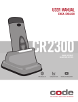
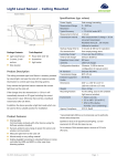
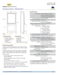
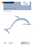
1
USER MANUAL V1.4 Pushbutton Transmitter Device PTM 210 / PTM 215 / PTM 210U / PTM 210J June 2014 Patent protected: US 6,747,573 US 7,019,241 Further patents pending EnOcean GmbH Kolpingring 18a 82041 Oberhaching Germany Phone +49.89.67 34 689-0 Fax +49.89.67 34 689-50 [email protected] www.enocean.com Subject to modifications PTM 210 / PTM 215 / PTM 210U / PTM 210J User Manual | v1.4 | June 2014 Page 1/20 USER MANUAL V1.4 PTM 210 / PTM 215 / PTM 210U / PTM 210J REVISION HISTORY The following major modifications and improvements have been made to the first version of this document: No 1.0 1.1 1.2 1.3 1.4 Major Changes Initial Release Updated operating force to typ. 8 N Merged PTM 210, PTM 215 and PTM 210U into one user manual Minor editsAdded PTM 210J incl. radio certificate Modification of PTM 215 Secure Mode Entry Published by EnOcean GmbH, Kolpingring 18a, 82041 Oberhaching, Germany www.enocean.com, [email protected], phone ++49 (89) 6734 6890 © EnOcean GmbH All Rights Reserved Important! This information describes the type of component and shall not be considered as assured characteristics. No responsibility is assumed for possible omissions or inaccuracies. Circuitry and specifications are subject to change without notice. For the latest product specifications, refer to the EnOcean website: http://www.enocean.com. As far as patents or other rights of third parties are concerned, liability is only assumed for devices, not for the described applications, processes and circuits. EnOcean does not assume responsibility for use of devices described and limits its liability to the replacement of devices determined to be defective due to workmanship. Devices or systems containing RF components must meet the essential requirements of the local legal authorities. The devices must not be used in any relation with equipment that supports, directly or indirectly, human health or life or with applications that can result in danger for people, animals or real value. Components of the devices are considered and should be disposed of as hazardous waste. Local government regulations are to be observed. Packing: Please use the recycling operators known to you. By agreement we will take packing material back if it is sorted. You must bear the costs of transport. For packing material that is returned to us unsorted or that we are not obliged to accept, we shall have to invoice you for any costs incurred. EnOcean GmbH Kolpingring 18a 82041 Oberhaching Germany Phone +49.89.67 34 689-0 Fax +49.89.67 34 689-50 [email protected] www.enocean.com Subject to modifications PTM 210 / PTM 215 / PTM 210U / PTM 210J User Manual | v1.4 | June 2014 Page 2/20 USER MANUAL V1.4 PTM 210 / PTM 215 / PTM 210U / PTM 210J TABLE OF CONTENT 1 1.1 1.2 1.3 1.4 1.5 1.6 2 2.1 2.2 2.3 2.3.1 2.3.2 2.3.3 3 3.1 3.2 3.3 4 4.1 4.2 4.3 GENERAL DESCRIPTION.................................................................................... 4 Basic Functionality ........................................................................................... 4 Typical Applications .......................................................................................... 5 Technical Data ................................................................................................. 6 Mechanical Interface......................................................................................... 6 Environmental Conditions................................................................................ 11 Ordering Information ...................................................................................... 11 FUNCTIONAL DESCRIPTION............................................................................. 12 Block Diagram ............................................................................................... 12 Contact Nipples Designation ............................................................................ 13 Operating modes ........................................................................................... 13 Normal mode operation (PTM 210, PTM 210U, PTM 210J, PTM 215)................... 13 Secure mode operation (PTM 215 only).......................................................... 14 Switching between modes (PTM 215 only)...................................................... 15 APPLICATIONS INFORMATION ......................................................................... 16 Construction of application specific Switch Rockers ............................................. 16 Device Mounting ............................................................................................ 16 Transmission Range ....................................................................................... 17 AGENCY APPROVALS ...................................................................................... 18 PTM 210 and PTM 215: CE Approval for the European Market .............................. 18 PTM 210U: FCC and Industry Canada Regulatory Statements .............................. 19 PTM 210J: Japanese Type Approval .................................................................. 20 EnOcean GmbH Kolpingring 18a 82041 Oberhaching Germany Phone +49.89.67 34 689-0 Fax +49.89.67 34 689-50 [email protected] www.enocean.com Subject to modifications PTM 210 / PTM 215 / PTM 210U / PTM 210J User Manual | v1.4 | June 2014 Page 3/20 USER MANUAL V1.4 PTM 210 / PTM 215 / PTM 210U / PTM 210J 1 GENERAL DESCRIPTION The pushbutton transmitter family PTM 21x from EnOcean enables the implementation of wireless remote controls without batteries. Power is provided by a built-in electro-dynamic power generator. PTM 21x devices support the 868 MHz, 902 MHz and 928MHz radio interface protocols of EnOcean. (1) Energy bow on both device sides (2) Contact nipples for switch rocker identification Rotation axis for pushbuttons or switch rocker Electro-dynamic powered radio transmitter device PTM 21x The PTM 21x product family contains the following product variants: PTM 210 868.300 MHz PTM 215 868.300 MHz with encryption capability PTM 210U 902.875 MHz PTM 210J 928.350 MHz 1.1 Basic Functionality PTM 21x devices contain an electro-dynamic energy transducer which is actuated by a bow (1). This bow is pushed by an appropriate push button, switch rocker or a similar construction mounted onto the device. An internal spring will release the energy bow as soon as it is not pushed down anymore. When the energy bow is pushed down, electrical energy is created and a radio telegram is transmitted including a 32-bit device ID. Releasing the energy bow similarly generates energy which is used to transmit a different radio telegram. It is therefore possible to distinguish between radio telegrams sent when the energy bar was pushed and radio telegrams sent when the energy bar was released. By identifying these different telegrams types and measuring the time between pushing and releasing of the energy bar, it is possible to distinguish between “Long” and “Short” EnOcean GmbH Kolpingring 18a 82041 Oberhaching Germany Phone +49.89.67 34 689-0 Fax +49.89.67 34 689-50 [email protected] www.enocean.com Subject to modifications PTM 210 / PTM 215 / PTM 210U / PTM 210J User Manual | v1.4 | June 2014 Page 4/20 USER MANUAL V1.4 PTM 210 / PTM 215 / PTM 210U / PTM 210J push button presses. This enables simple implementation of applications such as dimming control or blinds control including slat action.The PTM radio telegram identifies the status (pressed or not pressed) of the four contact nipples (2) when the energy bow was pushed or released. This enables the implementation of up to two switch rockers or up to four pushbuttons. PTM 215 devices support two operating modes - a normal mode and a secure mode with rolling code encryption to enable secure applications. PTM 210 / PTM 210U and PTM 210J devices support only normal mode. 1.2 Typical Applications Typical applications are found in the following areas: Building installation Industrial automation Consumer electronics Key products include wall-mounted switches and handheld remote controls supporting up to two rockers or up to four pushbuttons. The PTM 21x pushbutton transmitters are self-powered (no batteries) and therefore maintenance-free. They can be used in hermetically sealed systems or in remote (not easily accessible) locations. EnOcean GmbH Kolpingring 18a 82041 Oberhaching Germany Phone +49.89.67 34 689-0 Fax +49.89.67 34 689-50 [email protected] www.enocean.com Subject to modifications PTM 210 / PTM 215 / PTM 210U / PTM 210J User Manual | v1.4 | June 2014 Page 5/20 USER MANUAL V1.4 PTM 210 / PTM 215 / PTM 210U / PTM 210J 1.3 Technical Data Power supply Internal electro-dynamic power generator actuated by the energy bow Antenna Internal PCB antenna PTM 210: 868.300 MHz (ASK)1 PTM 215: 868.300 MHz (ASK)1 PTM 210U: 902.875 MHz (FSK) PTM 210J: 928.350 MHz (FSK) Frequency Data rate 125 kbps Conducted output power Channels PTM 210 / PTM 215 / PTM 210U: +5 dBm PTM 210J: 0dBm Two channels with two pushbuttons per channel Four action states per channel - upper/lower pushbutton is pressed/not pressed EnOcean Equipment Profile supported Security mode Rolling code with AES128 (PTM 215 only) Transmission range PTM 210 / PTM 215 / PTM 210U: typ. 300 m free field, typ. 30 m indoor PTM 210J: typ. 200m free field, typ. 30m indoor Individual 32-bit ID (factory programmed)2 Device identifier 1.4 F6-02-xx, F6-04-xx (PTM 210 / 215 normal mode) D2-03-00 (PTM 215 secure mode) Mechanical Interface Device dimensions (inclusive rotation axis and energy bow) Device weight 40.0 x 40.0 x 11.2 mm 20 g ± 1 g Energy bow travel / operating force 1.8 mm / typ. 8 N At room temperature Only one of the two energy bows may be actuated at the same time! Restoring force at energy bow typ. 0.7 N to 4 N Minimum restoring force of 0.5 N is required for correct operation Number of operations at 25°C Cover material typ. actuations tested according to VDE 0632 / EN 60669 Hostaform (POM) Energy bow material PBT (50% GV) 1 According the international standard for energy harvesting wireless radio protocol for self-powered applications: ISO/IEC 14543-3-10 2 PTM 210J: 48-bit ID possible, see 4.3 EnOcean GmbH Kolpingring 18a 82041 Oberhaching Germany Phone +49.89.67 34 689-0 Fax +49.89.67 34 689-50 [email protected] www.enocean.com Subject to modifications PTM 210 / PTM 215 / PTM 210U / PTM 210J User Manual | v1.4 | June 2014 Page 6/20 USER MANUAL V1.4 PTM 210 / PTM 215 / PTM 210U / PTM 210J PTM 21x without antenna, tilted view (including rocker catwalks) 1) these catwalks are not needed when using one single rocker only 2) dimensions of rocker part PTM 21x, top view (note cut A, B and C marking) EnOcean GmbH Kolpingring 18a 82041 Oberhaching Germany Phone +49.89.67 34 689-0 Fax +49.89.67 34 689-50 [email protected] www.enocean.com Subject to modifications PTM 210 / PTM 215 / PTM 210U / PTM 210J User Manual | v1.4 | June 2014 Page 7/20 USER MANUAL V1.4 PTM 210 / PTM 215 / PTM 210U / PTM 210J PTM 21x, cut A 2) dimensions of rocker part PTM 21x, cut B and C EnOcean GmbH Kolpingring 18a 82041 Oberhaching Germany Phone +49.89.67 34 689-0 Fax +49.89.67 34 689-50 [email protected] www.enocean.com Subject to modifications PTM 210 / PTM 215 / PTM 210U / PTM 210J User Manual | v1.4 | June 2014 Page 8/20 USER MANUAL V1.4 PTM 210 / PTM 215 / PTM 210U / PTM 210J Hatched areas: support planes PTM 21x rear view EnOcean GmbH Kolpingring 18a 82041 Oberhaching Germany Phone +49.89.67 34 689-0 Fax +49.89.67 34 689-50 [email protected] www.enocean.com Subject to modifications PTM 210 / PTM 215 / PTM 210U / PTM 210J User Manual | v1.4 | June 2014 Page 9/20 USER MANUAL V1.4 PTM 210 / PTM 215 / PTM 210U / PTM 210J 2) dimensions of rocker part PTM 21x, side view If the rocker is not mounted on the rotation axis of PTM 21x several tolerances have to be considered! The measure from support plane to top of the energy bow is 7.70 mm +/- 0.3 mm! The movement of the energy bow must not be limited by mounted rockers! Catwalks of the switch rocker must not exert continuous forces on contact nipples! EnOcean GmbH Kolpingring 18a 82041 Oberhaching Germany Phone +49.89.67 34 689-0 Fax +49.89.67 34 689-50 [email protected] www.enocean.com Subject to modifications PTM 210 / PTM 215 / PTM 210U / PTM 210J User Manual | v1.4 | June 2014 Page 10/20 USER MANUAL V1.4 PTM 210 / PTM 215 / PTM 210U / PTM 210J 1.5 Environmental Conditions Operating temperature -25 °C up to +65 °C Storage temperature -25 °C up to +65 °C Humidity 1.6 0% to 95% r.h. Ordering Information Type PTM 210 PTM 215 Ordering Code S3001-A210 S3001-A215 PTM 210U S3051-A210 PTM 210J S3061-A210 EnOcean GmbH Kolpingring 18a 82041 Oberhaching Germany Phone +49.89.67 34 689-0 Fax +49.89.67 34 689-50 [email protected] www.enocean.com Approvals CE, R&TTE, EN 300220 CE, R&TTE, EN 300220 FCC: Part 15.231 IC: RSS-210 MIC: ARIB STD-T108 Subject to modifications PTM 210 / PTM 215 / PTM 210U / PTM 210J User Manual | v1.4 | June 2014 Page 11/20 USER MANUAL V1.4 PTM 210 / PTM 215 / PTM 210U / PTM 210J 2 2.1 FUNCTIONAL DESCRIPTION Block Diagram Data Status Processor HF Contact Nipples Pushed/Released Ant DC Power Energy Bow N S Power Converter Block diagram of PTM 21x Energy Bow / Power Generator Converts the motion of the energy bow into electrical energy. Power Converter Converts the energy of the power generator into a stable DC supply voltage for the device electronics. Processor Determines the status of the contact nipples and the energy bow, encodes this status into a data word, encrypts this data word and the rolling code (PTM 215 only), generates the proper radio telegram structure and sends it to the radio transmitter. Radio transmitter Transmits the data in the form of a series of short EnOcean radio telegrams. EnOcean GmbH Kolpingring 18a 82041 Oberhaching Germany Phone +49.89.67 34 689-0 Fax +49.89.67 34 689-50 [email protected] www.enocean.com Subject to modifications PTM 210 / PTM 215 / PTM 210U / PTM 210J User Manual | v1.4 | June 2014 Page 12/20 USER MANUAL V1.4 PTM 210 / PTM 215 / PTM 210U / PTM 210J 2.2 Contact Nipples Designation PTM 21x devices provide four contact nipples. They are grouped into two channels (Channel A and Channel B) each containing two contact nipples (State O and State I). The state of all four contact nipples (pressed or not pressed) is transmitted together with a unique device identification (fixed 32-bit ID) whenever the energy bow is pushed or released. The picture below shows the arrangement of the four nipples and their designation: STATE O A CHANNEL B I Contact nipple designation 2.3 Operating modes Two operating modes exist for pushbutton transmitter devices: Normal mode: Supported on PTM 210, PTM 210U, PTM 210J and PTM 215 Secure mode: Supported on PTM 215 only After production, PTM 215 is set to “normal mode”. 2.3.1 Normal mode operation (PTM 210, PTM 210U, PTM 210J, PTM 215) In normal mode, PTM 210x and PTM 215 send telegrams according to EEP F6-02-xx and F6-04-xx as specified in the EnOcean Equipment Profiles specification. For more details refer to http://www.enocean-alliance.org/eep/ Due to the mechanical hysteresis of the energy bow, in most rocker switch device implementations, pressing the rocker sends an N-message and releasing the rocker sends a U-message! EnOcean GmbH Kolpingring 18a 82041 Oberhaching Germany Phone +49.89.67 34 689-0 Fax +49.89.67 34 689-50 [email protected] www.enocean.com Subject to modifications PTM 210 / PTM 215 / PTM 210U / PTM 210J User Manual | v1.4 | June 2014 Page 13/20 USER MANUAL V1.4 PTM 210 / PTM 215 / PTM 210U / PTM 210J 2.3.2 Secure mode operation (PTM 215 only) While operating in secure mode, PTM 215 sends secure telegrams in accordance to EEP D2-03-00 as specified in the EnOcean Equipment Profiles specification. For more details refer to http://www.enocean-alliance.org/eep/. These secure telegrams include a rolling code based on an incrementing counter which guarantees that identical message content will be encrypted differently for each telegram thus preventing replay attacks. The initial counter value is transmitted from PTM 215 to the receiver as part of the teach-in telegram when entering secure mode. Subsequent secure telegrams do not specify this counter value, therefore sender and receiver have to automatically increment their respective counters for each secure telegram to keep them synchronized. When telegrams are not received by the receiver this may lead to a de-synchronization of transmitter and receiver counters, i.e. the transmitter counter will have a greater value than the receiver counter. In order to prevent failure, the receiver will usually test the received rolling code against a defined window of future expected rolling codes and – if successful - resynchronize its counter automatically. The size of this rolling code window is defined on the receiver side. It is important that the amount of consecutive, non-received telegrams does not exceed the size of this window. For more details please refer to http://www.enocean.com/en/security-specification/. The rolling code is not transmitted with every telegram. It is only transmitted during teach-in. Afterwards the receiver has to increase the counter autonomously for each received message. It is strongly recommended to use PTM 215 in secure mode only in fixed installations with safe radio distance to avoid de-synchronization of sender and receiver. De-synchronization will occur if PTM 215 is operated outside the range of the receiver consecutively more often than the size of the rolling code window defined on the receiver. The same may apply if consecutive telegrams are lost on the receiver side due to power interruptions. In these cases it is necessary to set the receiver in LRN mode and teach-in the device again. Due to the enhanced telegram length of teach-in telegrams in secure mode, teachin is only possible at temperatures between 0 and 40°C. If the teach-in process is not successful, please repeat the procedure. Due to the enhanced telegram length of teach-in telegrams in secure mode only a single teach-in sub-telegram is sent at every actuation (no redundancy). EnOcean GmbH Kolpingring 18a 82041 Oberhaching Germany Phone +49.89.67 34 689-0 Fax +49.89.67 34 689-50 [email protected] www.enocean.com Subject to modifications PTM 210 / PTM 215 / PTM 210U / PTM 210J User Manual | v1.4 | June 2014 Page 14/20 USER MANUAL V1.4 PTM 210 / PTM 215 / PTM 210U / PTM 210J 2.3.3 Switching between modes (PTM 215 only) PTM 215 can be switched from normal mode to secure mode by simultaneously pressing both contact nipples of either rocker A or rocker B and actuating, releasing and actuating again the energy bow. The two contact nipples must remain pressed during the sequence of pressing, releasing and pressing again the energy bow. No additional contact nipple(s) might be pressed during that sequence. Otherwise the device will not enter secure mode. Upon entry into secure mode, a teach-in telegram is sent by PTM 215. The type of the teach-in telegram (Teach_In_Info : Type) is: 1-PTM. For more information on the structure of the teach-in telegram please refer to chapter 4.2 of http://www.enocean.com/en/security-specification/. PTM 215 can be switched from secure mode to normal mode by simultaneously pressing all four contact nipples of rocker A and rocker B and actuating the energy bow. Before changing the operating mode please make sure to clear the device from all receivers which have been taught to work with this device before. Otherwise the receiver will ignore the telegrams and the application will not work. Note that PTM 215 in normal mode will not send a data telegram when pressing two contact nipples belonging to the same channel and actuating the energy bow. This button combination is reserved for entry into secure mode. EnOcean GmbH Kolpingring 18a 82041 Oberhaching Germany Phone +49.89.67 34 689-0 Fax +49.89.67 34 689-50 [email protected] www.enocean.com Subject to modifications PTM 210 / PTM 215 / PTM 210U / PTM 210J User Manual | v1.4 | June 2014 Page 15/20 USER MANUAL V1.4 PTM 210 / PTM 215 / PTM 210U / PTM 210J 3 3.1 APPLICATIONS INFORMATION Construction of application specific Switch Rockers For CAD system development support, 3D construction data is available from EnOcean (IGS data). Using this data, the mechanical interface is fixed, and the shape and surface of the rocker(s) can be changed according to requirements. Polycarbonate is recommended as rocker material since it is both buckling resistant and wear-proof. It is also recommended to apply Teflon varnish in the areas of actuation. It is recommended using non-conductive material for the rockers to ensure best transmission range. Avoid if possible metallic materials or plastics with conducting ingredients such as graphite. 3.2 Device Mounting For mounting the PTM 21x device into an application specific case, the package outline drawings of the device are given in chapter 1.4. More detailed 3D construction data is available from EnOcean in IGS format. It is recommended not to mount the device directly onto metal surfaces or into metal frames since this can lead to significant loss of transmission range. EnOcean GmbH Kolpingring 18a 82041 Oberhaching Germany Phone +49.89.67 34 689-0 Fax +49.89.67 34 689-50 [email protected] www.enocean.com Subject to modifications PTM 210 / PTM 215 / PTM 210U / PTM 210J User Manual | v1.4 | June 2014 Page 16/20 USER MANUAL V1.4 PTM 210 / PTM 215 / PTM 210U / PTM 210J 3.3 Transmission Range The main factors that influence the system transmission range are: - Type and location of the antennas of receiver and transmitter - Type of terrain and degree of obstruction of the link path - Sources of interference affecting the receiver - “Dead spots” caused by signal reflections from nearby conductive objects. Since the expected transmission range strongly depends on this system conditions, range tests should always be performed to determine the reliably achievable range under the given conditions. The following figures for expected transmission range are considered by using a PTM, an STM or a TCM radio transmitter device together with a TCM radio receiver device with preinstalled whip antenna. These figures should be treated as a rough guide only: - Line-of-sight connections Typically 30 m range in corridors, up to 100 m in halls - Plasterboard walls / dry wood Typically 30 m range, through max. 5 walls - Ferro concrete walls / ceilings Typically 10 m range, through max. 1 ceiling - Fire-safety walls, elevator shafts, staircases and similar areas should be considered as shielded The angle at which the transmitted signal hits the wall is very important. The effective wall thickness – and with it the signal attenuation – varies according to this angle. Signals should be transmitted as directly as possible through the wall. Wall niches should be avoided. Other - factors restricting transmission range include: Switch mounting on metal surfaces (up to 30% loss of transmission range) Hollow lightweight walls filled with insulating wool on metal foil False ceilings with panels of metal or carbon fibre Lead glass or glass with metal coating, steel furniture The distance between EnOcean receivers and other transmitting devices such as computers, audio and video equipment that also emit high-frequency signals should be at least 0.5 m. A summarized application note to determine the transmission range within buildings is available from www.enocean.com. EnOcean GmbH Kolpingring 18a 82041 Oberhaching Germany Phone +49.89.67 34 689-0 Fax +49.89.67 34 689-50 [email protected] www.enocean.com Subject to modifications PTM 210 / PTM 215 / PTM 210U / PTM 210J User Manual | v1.4 | June 2014 Page 17/20 USER MANUAL V1.4 PTM 210 / PTM 215 / PTM 210U / PTM 210J 4 AGENCY APPROVALS 4.1 PTM 210 and PTM 215: CE Approval for the European Market The devices bear the EC conformity marking CE and conform to the R&TTE EU-directive on radio equipment. The assembly conforms to the European and national requirements of electromagnetic compatibility. The conformity has been proven and the corresponding documentation has been deposited at EnOcean. The PTM devices can be operated without notification and free of charge in the area of the European Union, and in Switzerland. The following provisos apply: EnOcean RF devices must not be modified or used outside their specification limits. EnOcean RF devices may only be used to transfer digital or digitized data. Analog speech and/or music are not permitted. The final product incorporating EnOcean RF devices must itself meet the essential re- quirement of the R&TTE Directive and a CE marking must be affixed on the final product and on the sales packaging each. Operating instructions containing a Declaration of Conformity has to be attached. If transmitters are used according to the regulations of the 868.300 MHz band, a so-called “Duty Cycle” of 1% per hour for each transmitter must not be exceeded. Permanent transmitters such as radio earphones are not allowed. For conventional applications, it must be ensured that the PTM 215 or PTM 210 radio device is not operated more than 6000 times within one hour (one operation: energy bow is pressed and released). Within this calculation, the extraordinary short telegram length is considered including three subtelegrams. Also a tolerance of 5% in the telegram length is included. EnOcean GmbH Kolpingring 18a 82041 Oberhaching Germany Phone +49.89.67 34 689-0 Fax +49.89.67 34 689-50 [email protected] www.enocean.com Subject to modifications PTM 210 / PTM 215 / PTM 210U / PTM 210J User Manual | v1.4 | June 2014 Page 18/20 USER MANUAL V1.4 PTM 210 / PTM 215 / PTM 210U / PTM 210J 4.2 PTM 210U: FCC and Industry Canada Regulatory Statements This device complies with part 15 of the FCC rules and Industry Canada ICES- 003. Operation is subject to the following two conditions: (1) This device may not cause harmful interference, and (2) this device must accept any interference received, including interference that may cause undesired operation. Any changes or modifications not expressly approved by manufacturer could void the user’s authority to operate the equipment. When the product is placed on the US / Canadian market, it must carry the Specified Radio Equipment marking as shown below: FCC ID: IC: SZV-PTM210U 5713A-PTM210U IMPORTANT! Any changes or modifications not expressly approved by the party responsible for compliance could void the user’s authority to operate this equipment. Le présent appareil est conforme aux CNR d’Industrie Canada applicables aux appareils radio exempts de licence. L’exploitation est autorisée aux deux conditions suivantes: (1) l’appareil ne doit pas produire de brouillage, et (2) l’utilisateur de l’appareil doit accepter tout brouillage radioélectrique subi, meme si le brouillage est susceptible d’en compromettre le fonctionnement. IMPORTANT! Tous les changements ou modifications pas expressément approuvés par la partie responsable de la conformité ont pu vider l’autorité de l’utilisateur pour actioner cet équipment. EnOcean GmbH Kolpingring 18a 82041 Oberhaching Germany Phone +49.89.67 34 689-0 Fax +49.89.67 34 689-50 [email protected] www.enocean.com Subject to modifications PTM 210 / PTM 215 / PTM 210U / PTM 210J User Manual | v1.4 | June 2014 Page 19/20 USER MANUAL V1.4 PTM 210 / PTM 215 / PTM 210U / PTM 210J 4.3 PTM 210J: Japanese Type Approval PTM 210J complies with the Japanese radio law and is certified according to ARIB STD-T108 V1.0 (2012-02). There is a certification marking on the back side of the module. When the product is placed on the Japanese market, it must carry the Specified Radio Equipment marking as shown below: If the certification label cannot be recognized from outside (e.g. installation in a host) appropriate information must be referenced in the user manual. Using the key combination A0+A1+B1 (see contact nipples designation), PTM 210J transmits a telegram with 48-bit ID as required by Japanese radio law. EnOcean GmbH Kolpingring 18a 82041 Oberhaching Germany Phone +49.89.67 34 689-0 Fax +49.89.67 34 689-50 [email protected] www.enocean.com Subject to modifications PTM 210 / PTM 215 / PTM 210U / PTM 210J User Manual | v1.4 | June 2014 Page 20/20