1
®
917.251551
OWNER'S MANUAL
o Assembly
o Operation
o Customer Responsibilities
o Service and Adjustments
o Repair Parts
CAUTION:
Read and follow
FOR CONSUMER
all safety
ASSISTANCE
rules
and instructions
before
operating
HOT LINE, CALL THIS TOLL FREE NUMBER:
this equipment.
1-800-659-5917
SAFETY RULES
Safe Operation Practices for Ride-On Mowers
A
IMPORTANT:
THIS CUTTING MACHINE IS CAPABLE OF AMPUTATING
HANDS AND FEET AND THROWING OBJECTS_
FAILURE TO OBSERVE THE FOLLOWING SAFETY INSTRUCTIONS
COULD RESULT IN SERIOUS INJURY OR DEATH.
i.
•
•
•
•
•
•
•
•
•
•
•
•
•
•
•
GENERAL OPERATION
Read, understand,and follow all instructions in the manual
and on the machinebeforestarting.
Only allow respons{bleadults, who are familiar with the
instructions,to operate the machine.
Clear the area of objectssuch as rocks,toys, wire, etc,
whichcouldbe pickedup and thrownbythe blade.
Besurethe areaisclear ofotherpeoplebefore mowing. Stop
machineif anyone entersthe area.
Never carry passengers
Do not mow in reverseunlessabsolutelynecessary Always
lookdownand behindbeforeand whilebacking.
Be aware ofthe mower dischargedirectionand do notpoint
it at anyone. Do not operatethe mowerwithouteitherthe
entire grass catcheror the guard in place_
Slow downbeforeturning.
Never leave a runningmachine unattended_Alwaysturnoff
blades, set parkingbrake, stop engine,and remove keys
beforedismounting.
Turn offblades when not mowing.
Stop engine before removinggrasscatcher or unclogging
chute_
Mow onlyin daylightor goodartificiatlight.
Do not operate the machinewhile under the influenceof
alcoholor drugs.
Watch fortrafficwhen operatingnear or crossingroadways_
Use extracare when loadingor unloadingthe machine into
a trailer or truck_
Iii. CHILDREN
Tragic accidents can occur' if the operator is not alert to the
presence of children.
Children are often attracted to the
machine and the mowing activity.
Never assume that
children will remain where you last saw them.
°
Keep children out of the mowing area and under the watchful
care of another responsible adul[
•
Be alert and turn machine off if children enter the area.
•
Before and when backing, look behind and down for small
children.
Never carry children.. They may fall off and be seriously
injured or interfere with safe machine operation_
•
Never allow children to operate the machine.
°
Use extra care when approaching blind corners, shrubs,
trees, or other objects that may obscure vision.
IV.
SERVICE
•
Use extra care in handling gasoline and other fuels. They are
flammable and vapors are explosive.
Use only an approved container.
Never remove gas cap or add fuel with the engine
running Allow engine to cool before refueling. Do not
smoke.
Never refuel the machine indoors.
Never store the machine or fuel container inside where
there is an open flame, such as a water heater.
Never run a machine inside a closed area
Keep nuts and bolts, especially blade attachment bolts, tight
and keep equipment in good condition.
Never tamper with safety devices
Check their proper
operation regularly.
Keep machine free of grass, leaves, or other debris build-up
Clean oil or fuel spillageo AUow machine to cool before
storing_
Stop and inspect the equipment if you strike an object.
Repair, if necessary, before restarting
Never make adjustments or repairs with the engine running.
Grass catcher components are subject to wear, damage, and
deterioration, which could expose moving parts or allow
objects to be thrown, Frequently check components and
replace with manufacturer's recommended parts, when nero
essary_
Mower blades are sharp and can cut. Wrap the blade(s) or
wear gloves; and use extra caution when servicing them.
Check brake operation frequently.
Adjust and service as
required°
°
°
I1. SLOPE OPERATION
•
Slopes are a major factor related to loss-of-control
and
tipover accidents, which can result in severe injury or death.
All slopes require extra caution, if you cannot back up the
slope or' if you feel uneasy on it, do not mow it.
•
•
DO:
°
Mow up and down slopes, not across.
Remove obstacles such as rocks, tree limbs, etc.
•
Watch for holes, ruts, or bumps.
Uneven terrain could
overturn the machine. Tall grass can hide obstacles.
°
Use slow speed. Choose a low gear so that you will not have
to stop or shift while on the slope.
°
Follow the manufacturer's
recommendations
for wheel
weights or counterweights to improve stability.
•
Use extra care with grass catchers or other attachments.
These can change the stability of the machine.
•
Keep aUmovement on the slopes slow and gradual. Do not
make sudden changes in speed or direction.
•
Avoid starting or stopping on a slope. If tires lose traction,
disengage the blades and proceed slowly straight down the
slope.
•
°
•
.............t,ook for ihis
,
, ,, ,,,
to point out im-
CAUTIONH!
BECOME
ALERT!!!It means
YOUR
portant
safety
precautions.
SAFETY IS INVOLVED.
A
DO NOT:
•
Do not turn on slopes unless necessary, and then, turn slowiy
and gradually downhill, if possible.
•
Do not mow near drop-otis, ditches, or embankments.. The
mower could suddenly turn over if a wheel is over the edge
of a cliff or ditch, or if an edge caves in.
=
Do not mow on wet grass. Reduced traction could cause
sliding.
°
Do not try to stabilize the machine by putting your foot on the
ground.
°
Do not use grass catcher on steep slopes.
symbol
,,,, ,,,, ,,
A
,,,,,,,,,,,,,,,,,,,,
,,,,,,,,
CAUTION: Always disconnect spark plug
wire and place wire where it cannot contact
spark plug in order to prevent accidental
starting when setting up, transporting,
adjusting or making repairs.
A WARNING
The engine exhaust from this product contains chemicals known to the State of Cahfornia to cause cancer, birth defects, or other
reproductive
harm.
2
CONGRATULATIONS
on your purchase of a Sears
Tractor° it has been designed, engineered and manufac-.
tured to give you the best possible dependability and
performance.
PRODUCT
Should you experience any problem you cannot easily
remedy, please contact your nearest Sears Authorized
Service CentedDepartmento
We have competent, welltrained technicians and the proper tools to service or repair
this tractor_
Please read and retain this manual. The instructions will
enable you to assemble and maintain your unit properly,.
Always observe the "SAFETY RULES"..
MODEL
NUMBER
SPECIFICATIONS
HORSEPOWER:
22,5
GASOLINE CAPACITY
AND TYPE:
3,,5 GALLONS
UNLEADED REGULAR
OIL TYPE (API-SF/SG):
SAE 10W30 (above 32°F)
SAE 5W-30 (below 32°F)
OIL CAPACITY:
W/FILTER:
4,2 PINTS
W/O FILTER: 3°7 PINTS
SPARK PLUG:
(GAP: _030")
CHAMPION
VALVE CLEARANCE:
NOT ADJUSTABLE
GROUND SPEED (MPH):
Forward
1st
2rid
3rd
Reverse
TRANSAXLE OIL
CAPACITY AND TYPE:
4 QUARTS
SAE 30 API-SG
TIRE PRESSURE:
FRONT:
REAR:
CHARGING SYSTEM:
"t5 AMPS @ 3600 RPM
BATTERY:
AMP/HR:
MIN CCA:
CASE SIZE:
BLADE BOLT TORQUE:
30-35 FT, LBS,
917,251551
SERIAL
NUMBER
DATEOF PURCHASE
THE MODELAND SERIAL NUMBERS WILL BE FOUND
ON A PLATE UNDER THE SEAT.
YOU SHOULD RECORD BOTH SERIAL NUMBER AND
DATE OF PURCHASE AND KEEP IN A SAFE PLACE
FOR FUTURE REFERENCE.
MAINTENANCE
AGREEMENT
A Sears Maintenance
Agreement is available on this product,, Contact your nearest Sears store for details_
CUSTOMER
RC12YC
LO
0,7
1.4
2.3
0,9
HI
1,7
33
54
2 1
14 PSI
10 PSI
35
280
UtR
RESPONSIBILITIES
"
Read and observe
the safety
.
Follow a regular schedule
using your tractor,,
•
Follow the instructions
under"Custor:ner
Responsibilities" and "Storage" sections of this owner's manual°
ered land unless the engine's exhaust system is equipped
with a spark arrester meeting applicable local or state laws
(if any). If a spark arrester is used, it should be maintained
in effective working order by the operator.
rules.,
in maintaining,
caring for and
In the state of California the above is required by law
(Section 4442 of the California Public Resources Code),.
Otherstates may have similar lawso Federal laws apply on
federal lands,. A spark arrester for the muffler is available
through your nearest Sears Authorized Service Center/
Department (See REPAIR PARTS section of this manual).
WARNING:
This tractor is equipped with an internal
combustion engine and should not be used on or near any
unimproved forest-covered, brush-covered or grass-coy-
LliVlmTEDTWO YEAR WARRANTY
ON ELECTRIC START RIDING EQUIPMENT
For two (2) years from the date of purchase, if this riding equipment is maintained, lubricated and tuned up according to the
instructions in the owner's manual, Sears will repair or replace, free of charge, any parts found to be defective in material or
workmanship
This Warranty does not cover:
o
o
°
-
Expendable items which become worn during normal use, such as blades, spark plugs, air cleaners and belts_
Tire replacement or repair caused by punctures from outside objects, such as nails, thorns, stumps, or glass,
Repairs necessary because of operator abuse, negligence, improper storage or accident or the failure to maintain the
equipment according to the instructions contained in the owner's manual,,
Riding equipment used for commercial or rental purposes,,
LIMITED 90 DAY WARRANTY
ON BATTERY
For ninety (90) days from date of purchase, if any battery included with this riding equipment proves defective in material or
wo[kmanship and our testing determines the battery will not hold a charge, Sears will replace the battery at no charge,
WARRANTY SERVICE
CENTER/DEPARTMENT
IS AVAILABLE BY RETURNING
IN THE UNITED STATES.
THE RIDING
EQUIPMENT
TO THE NEAREST
SEARS SERVICE
This Warranty gives you specific legal rights, and you may also have other rights which may vary from state to state.
SEARS, ROEBUCK AND CO., D/817 WA, HOFFMAN ESTATES, ILLINOIS 60179
3
TABLE OF
SERVICE AND ADJUSTMENTS
...........................
20-27
STORAGE
................................................
_.................. 28
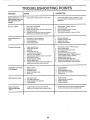
TROUBLESHOOTING
.....................
......................
29-30
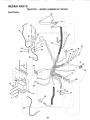
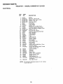
REPAIR PARTS -TRACTOR
........................
.... .... 32'49
REPAIR PARTS - ENGINE ....................................
50-57
PARTS ORDERING/SERVICE
...............
BACK COVER
SAFETY RULES ............................................................
2
PRODUCT SPECIFICATIONS ......................................
3
CUSTOMER RESPONSIBILITIES .... ..,......,.. .... 3, 16-19
ASSEMBLY .............................................................
7-10
OPERATION ;.........................................................
11-15
MAINTENANCE SCHEDULE .....................................
16
MNDEX
E
A
Electrical:
Interlocks and Relays .....................24
Adjustments:
Schematic ..................................
31
Brake ...........................................................
22
Wiring Diagram ......................................
32
Carburetor .................................................
27
Engine:
Clutch Pulley ...........................................
22
Air Filter'. ..............................................
19
Gauge Wheels ....................................
14
Air Screen ..........................................19
Mower
Front-To-Back ..............................21
Cooling Fins ......................................I9
Side-To-Side .......................................
20
Oil Change ...................................
18
Oil Level ...................................... t4,18
Throttle Control Cabie ........................
26
Oil Type ............................................. 18
Air Filter', Engioe ...........................................
19
Preparation ............................................
14
Air Screen, Engine .......................................
19
Repair Parts .....................................
50-57
Assembly ......................................................
L,, 7-10
Starting .............................................. 15
Storage .................................................
28
Accessories ................................................. 5
B
Batter,/:
Charging .................................................
8
Cleaning ................................................
18
Starting with Weak Battery ............24
Storage ........................................................
28
Terminals .................................................
18
Belt:
Motion Drive
Remova!iReplacement
........... 23
Mower Drive
Removal/Replacement
.............21
Mower Blade Drive
Removal/Replacement
............ 22
Blade:
Sharpening ...................................... 17
Replacement .........................................
17
Brake Adjustment .......................................22
C
Carburetor Adjustment .................................
27
Clutch Pulley .................................................
22
Controls, Tractor ..............................................
12
Customer Responsibilities ...............16-19
Engine:
Air Filter ...............................................
19
Air Scree ..............................................
19
Cooling Fins ..........................................
19
Engine Oil .........................................
18
Fuel Filter .............................................
19
Spark Plug(s) .................................19
Tractor."
Battery .................................................
18
Blade .............................................. 17
Lubrication Chart ..........................16
Maintenance Schedule ............. I6
Tire Care ...................................
8,17,24
Transaxle .......................................17
Cutting Height, Mower ...............................
13
F
Filter:
Air Filter ......................................... 19
Fuel .......... :.........................................19
Oil .................................................... 18
Fuel:
Storage .................................................
28
Type .........................................................
13
Fuse ............................................................24
H
Headlights .....................................................
24
Hood Removal/Installation .................... 25
L
Leveling Mower Deck .......................... 20
Lubrication:
Chart ....................................................16
M
Maintenance Schedule ...........................16
Mower:
Adjustment, Front-to-Back ............ 21
Adjustment, Side-to-Side .............. 20
Blade Sharpening .......................... I7
Blade Replacement ..........................17
Cutting Height ........................................
13
Installation ...... :
20
Operation ............................................14
Removal ............................................ 20
..............................
Mowing Tips .................................................
15
Muffler ..........................................................19
Spark Arrester ................................3,40
O
Oil:
Cold Weather Conditions ..........14,18
Engine .................................................18
Storage ..............................................28 "
4
Operation ................................................
11-15
Operating Mower ........................................
t4
Options:
Accessories ............................................
5
Spark Arrester .............................. 3,40
P
Parking Brake ...............................................
13
Parts Bag .......................................................6
Parts, Replacement/Repair
................32-49
Product Specifications .................................3
R
Repair Parts .............................................
32-49
S
Safety Rules ......................................................
2
Seat ............................................................ 8
Service and Adjustments ..................20-27
Carburetor. ......;.....................................
27
Clutch Pulley .........................................
22
Fuse ................................................... 24
Hood Remova!llnstallation
..... :..... 25
Motion Drive Belt
Removal/Replacement
............. 23
Mower Dive Belt
RemovallReplacement
..............21
Mower Blade Drive
Remova!lReplacement
........... 22
Mower Adjustment
Front-to-Back ..................................
21
Side-to-Side ............................... 20
Mower Removal ..................................
20
Tir.e Care ...................................8,17,24
Slope Guide Sheet ...................................59
Spark Plug(s) ...............................................
19
Specifications ................................................3
Starting the Engine .............................14-15
Steering Wheel ...........................................
7,23
Stopping the Tractor ....................................
13
Storage ........................................................28
T
ThrottleControl
Cable Adjustment ........26
Tires ......................................................
8,17,24
Trouble Shooting Chart .......................
29-30
Transaxle .......................................................
17
W
Warranty .........................................................................
3
Wiring Diagram ........................................ 32
Wiring Schematic ......................................31
ACCESSORmES AN
ATTACH
ENTS
_LLLLLL_
These accessories and attachments were available through most Sears retail outlets and service centers when the tractor was purchased.
Most Sears stores can order these items for you when you provide the model number of your tractor..
MAINTENANCE
ENGINE
SPARK PLUG
GAS CAN
ENGINE OIL
FUEL STABILIZER
AIR FILTER
BLADES
BELTS
PERFORMANCE
Sears offers a wide variety of attachments that fit your tractor
you. This list was current at the time of publication; however,
may be made in these attachments, or some may no longer
accessories and attachments
that are available for your
Most of these attachments do not require additional hitches
attaching and detaching
Many of these are listed below with brief explanations of how they can help
it may change in future years - more attachments may be added, changes
be available or fit your model.. Contact your nearest Sears store for the
tractor.
or conversion kits (those that do are indicated) and are designed for easy
,.
AERATOR promotes deep root growth for a healthy lawn Tapered
25-inch steel spikes mounted on 10-inch diameter discs puncture
holes in soil at close intervals to let moisture soak in, Steel weight tray
for increased penetration'.
BUMPER protects front end of tractor from damage.
SLEEVE CULTIVATOR is 43 inches wide,. Prepares ground for
seeding, helps weed control.. Steel frame holds 5 adjustable sweeps.
Adjusts vertically, horizontally (Requires sleeve hitch) Optional
accessory:
steel furrow opener for wider openings for potatoes,
corn, and other deep-seeded crops.
SLEEVE HITCH for use with master lift system. Single pin couples!
uncouples
SNOWTHROWER has 42-inch swath Drum-type auger handles
powdery and wet,/heavy snow. Mounts easilywith simple pinarrangement Discharge chute adjusts from tractor seat 6-inch diameter
spout discharges snow 10 to 50 feet Lift controlled at tractor seat,
(Use with chains and wheel weights and!or rear drawbar weight.)
SPRAYERS use 12-volt DC electric motor that connects to the tractor
battery or other 12-volt source
Includes booms for automatic
spraying and hand held wand for spot spraying. Wand has adjustable
spray pattern. For applying herbicides, insecticides, fungicides and
liquid fertilizers.
SPREADER/SEEDERS make seeding, fertilizing, and weed killing
easy Broadcast spreaders are also useful for granular de-icers and
sand.
CARTS make hauling easy Variety of sizes available, plus accessories such as side panel kits, tool caddy, cart cover, protective mat and
dolly
CORING AERATOR takes small plugs out of soil to allow moisture
and nutrientsto reach grass roots. 36-inch swath 24 hardened steel
coring tips 150 Ib capacity weight tray
DISC HARROW has 2 gangs of 4 steel blades that angle from 10 to
20 degrees, 40 inches wide Can hook 2 units in tandem (Requires
sleeve hilch )
DOZER BLADE removes snow; grades dirt, sand and gravel 48
inches wide, 17 inches high, clears 44-inch path when angled. Master
lift control lever for operator ease. Spring trip for snow removal on
uneven pavement; built-in float for blade to follow ground contour.
Reversible, replaceable scraper bar, (Use with tire chains and wheel
weights and/or rear drawbar weight )
EASY OIL DRAIN VALVE makes oil changes easier, faster
FRONT NOSE ROLLER canters in front of mower deck to reduce
chances of "scalping" on uneven terrain
SWEEPERS let you collect grass clippings and leaves
TILLER has8 hp engine to prepare seed beds, cultivate, and compost
garden residue, Chain-drive transmission. Six 11-inch diameterone
piece heat-treated steel tines, Tills 30-inch path (Requires sleeve
hitch) Or use 5 hp tow-behind TILLER with 36-inch swath to prepare
seed beds, cultivate and compost garden residue. Tiller has its own
built-in lift and depth control system and does NOT require a sleeve
hitch Fits any lawn, yard or garden tractor Simply hook up to the
tractor drawbar and go! Optional accessories for 5 hp tiller convert
unit for dethatching, aerating, hilling..without tools
TIRE CHAINS are heavy duty; closely spaced extra-large cross links
give smooth ride, outstanding traction
GANG HITCH lets you tow 2 or 3 pull-behind attachments at
once, such as sweepers, dethatchers, aerators (not for use with
rollers, carts or other heavy attachments).
MULCH RAKE/DETHATCHER loosens soil and flips thatch and
matted leaves to lawn surface for easy pickup, Twenty spring tine
teeth. Useful to prepare bare areas for seeding. Available for front or
rear mounting. HIGH PERFORMANCE REEL-ACTION SPRING
TINE DETHATCH ER covers 36-inch wide path and losses thatch into
large hopper. Mounts behind tractor.
PLOW turns soil 6 inches deep, cuts 10-inch furrow. Crank adjustment controls depth, 3-position yoke sets width. Heavy steel landside
for straight furrowing. (Requires sleeve hitch.)
RAMP TOPS AND FEET let you load and unload tractor from a
pickup truck Use with 2 x 8 or2 x 10 lumber.
REAR GRADER BLADE is 42 inches wide and operated from driver's
seat. Reversible steel blade can be angled at 30 degrees for grading,
Reverses for pushing snow backwards (Requires sleeve hitch)
ROLLER for smoother lawn surface, 36-inch wide, !8-inch diameter
water-tight drum holds up to 390 Ibs of weight° Rounded edges
prevent harm to tuff. Adjustable scraper automatically cleans drum
TRACTOR CAB has heavy duty vinyl fabric over tubular steel frame,
ABS plastic top; clear plastic windshield offers 360 degree visibility.
Hinged metal doors with catch. Keeps operator warm and dry_
Remove vinyl sides and windshields for use as sun protector in
summer. Optional accessories include:
tinted/tempered solid
safety glass windshield with hand operated wiper; 12-volt amber
caution light for mounting on cab top.
VACS for powerful collection of heavy grass clippings and leaves.
Optional wand attachment to pick up debris in hard-to-reach places..
VAC/CHIPPER includes a chipper-shredder.
WEtGHTBRACKET for drawbar forsnow removal applications. Can
be mounted on front of tractor for plowing applications. Uses (1) 55
lb weight.
WHEEL WEIGHTS for rear wheels provide needed traction for snow
removal or dozing heavy materials
5
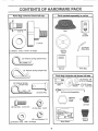
CONTENTS
..............
i ,,,,i
OF
AIRIDWARE PACK
mn
............
i,,111111,11,1
Parts Bag contents
n,r
' "1"11'
Parts packed separately
shown full size
....................................
in carton
i
---q
I
I
(1) Shoulder Bolt
5/! 6-18
Seat
Video
Cassette
|
I
!
(1) Knob
/(2)
(1) Washer
17/32 x !_3/16 x 12 Gauge
Gauge
Wheel Bar's
Steering
Wheel
!
Manuaf
......................
4)..__ai_ier'
Springs (single loop)
Parts Bag
. ...............
•...................
Parts bag contents
_
,,lit, ii
(2) Hex Bolts 1/4-20 x 3/4
_(2)
(4) Clevis Pins
I1'
"1
,,i
:::
,',
(2)washers
Front Link Assemblies
]_
(2) Keys
(2) Hex Nuts 1/4-20
114
Slope Sheet
9/32 x 5/8 x 16 Gauge
6
3/8
_
x718xt4Gauge
(2) Gauge _
(2) CenterWheels
_
lock Nuts
Whee!
Steering
Insert
@
(2) Lock Washers
(2) Washers
/_"_
/
/_)
(2) ShoulderBotts
l\, (_/
_"
t
"
............................
,,_'_
(4) Retainer Springs
I
not shown full size
Steering
Sleeve
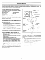
ASSEMBLY
...........................................
i,
,
L _
llln,i ,,ll,i
ii
UHHUHH,/',' nl I' I I
' I' I
Your new tractor has been assembled at the factory with the exception of those parts left unassembled for shipping pu rposes_
To ensure safe and proper operation of your tractor all parts and hardware you assemble must be tightened securely, Use
the correct tools as necessary to insure proper tightness.
TOOLS
REQUIRED
FOR ASSEMBLY
STEERING
WHEEL
A socket wrench set will make assembly easier. Standard
wrench sizes are listed..
(2) 7/16" wrenches
(I)
1/2" wrench
Tire pressure gauge
. Utility knife
(1) 9/16" wrench
(1) 3/4" socket with drive ratchet
LARGE FLAT
WASHER
When right or left hand is mentioned in this manual, it
means when you are in the operating position (seated
behind the steering wheel).
STEERING
TO REMOVE TRACTOR FROM CARTON
UNPACK
CARTON
•
Remove all accessible loose parts and parts cartons
from carton (See page 6)_
•
Cut, from top to bottom, along lines on all four corners
of carton, and lay panels ftaL
o
Remove mower and packing materials.
o
Check for any additional loose parts or cartons and
remove,
STEERING
ADAPTER
J
BEFORE ROLLING TRACTOR
OFF SKID
STEERING
SLEEVE
ATTACH STEERING WHEEL (See Fig. 1)
lI
_
_i/i
_
i
II
!/
_ _ I,/
/
/
FIG. 1
°
Remove hex bolt, lock washer and large flat washer
from steering shaft,
°
Position front wheels of the tractor so they are pointing
straight forward.
•
Slide steering sleeve over steering shaft°
°
Position steering wheel so cross bars are horizontal
(left to right) and slide onto steering wheel adapter°
°
Press lift lever plunger and raise _.ttachment lift lever to
its highest position.
•
Secure steering wheel to steering shaft with hex bolt,
lock washer and large flat washer previously removed
Tighten securely.
°
=
•
Release parking brake by depressing clutch/brake
pedal
Place gearshift lever in neutral (N) position_.
Roll tractor forward off skid.
•
°
Remove mower and packing materials.
Remove ties from V-belts
°
TO ROLL TRACTOR
OFF SKID (See Operation section for location and function
of controls)
Snap steering wheel insert into center of steering
wheel..
o
Remove protective plastic from tractor hood and grill.
IMPORTANT: CHECK FOR AND REMOVE ANY SZAPLES
1NSKID THAT MAY PUNCTURE TIRES WHERE TRACTOR
1S TO ROLL OFF SKID
7
LY
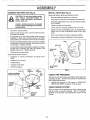
CONNECT
BATTERY
(See Fig. 2)
INSTALL
Adjust seat before tightening adjustment knob_
CAUTION: Do not short battery terminalso Before connecting battery, remove metal bracelets,
wristwatch
bands, rings, etc.
Positive terminal must be connected
first to prevent sparking from accidental grounding_
o
Lift hood to raised position..
I
Open terminal access doors, remove terminal protective caps and discard.
if this battery is put into service after month and year
indicated on label (label ]ocated between terminals)
charge battery for minimum of one hour at 6-10 amps.
°
First connect RED battery cable to positive (+) battery
ter minat with hex bolt, flat washer, lock washer and hex
nut as shown. Tighten securely_
-
Connect BLACK grounding cable to negative (-) battery
terminal with remaining hex bolt, flat washer, lock
washer and hex nut. Tighten securely.
=
SEAT (See Fig. 3)
o
o
Remove cardboard packing on seat pan_
Place seat on seat pan and assemble shoulder boll
o
Assemble adjustment
Do not tighten.,
•
Tighten shoulder bolt securely.
°
Lower seat into operating position and sit on seal
°
Slide seat until a comfortable position is reached which
allows you to press clutch/brake pedal all the way
down..
°
Get off seat without moving its adjusted position.
=
Raise seat and tighten adjustment knob securely.
knob and flat washer loosely.
SEAT PAN
SEAT_
_/_
Close terminal access doors.
Use terminal access doors for:
°
inspection for secure connections
ware).
.
Inspection for corrosion..
°-
Testing battery,
°
Jumping (if required).
o
Periodic charging.
_FLAT
WASHER
ADJUSTMENT
KNOB
HEX NUT
DISCARD TERMINAL
PROTECTIVE
CAPS
(to tighten hard _
LOCK
WASHER
FIG. 3
FLAT
WASHER
HEX
BOLT
\\
CHECK
TIRE PRESSURE
The tires on your tractor were overinflated at the factory for
shipping purposes. Correct tire pressure is important for
best cutting performance.
TERMINAL.... ;'
ACCESS
DOOR
_,,
,,
°
POSITIVE
(RED)
CABLE
!
Reduce tire pressure to PSi shown in "PRODUCT
SPECIFICATIONS" on page 3 of this manual.
CHECK
BRAKE
SYSTEM
After you learn how to operate your tractor, check to see
that the brake is properly adjusted_ See 'q'O ADJUST
BRAKE" in the Service and "Adjustments section of this
manual.
NEGATIVE
(BLACK)
CABLE
FIG. 2
8
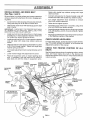
ASSEM
LY
INSTALL MOWER AND DRIVE BELT
(See Figs. 4 and 5)
Retain with double loop retainer springs with loops
down as shown,,
Be sure tractor is on level surface and mower suspension
arms are raised with attachment lift control, Engage parking brake°
o
o
Cut and remove ties securing anti-sway bar and belts,,
Swing anti-sway bar to left side of mower deck°
Slide mower under tractor with discharge guard to right
side of tractor.
IMPORTANT;
CHECK BELT FOR PROPER ROUTING 1N
ALL MOWER PULLEY GROOVES.
INSTALL BELT INTO
ELECTRIC CLUTCH PULLEY GROOVE,
•
Install one front link in top hole of the LH. front mower
bracket and LH, front suspension bracket. Retain with
two single loop retainer springs as shown_
o
Install second front link in Roll. front suspension bracket
only and retain with single loop retainer spring as
shown,,
o
Slide right side of mower back and install link in top hole
of R,H, front mower bracket° Retain with single loop
retainer spring as shown_
.
Turn height adjustment knob counterclockwise
stops°
•
Lower mower linkage with attachment lift control.,
°
Place the suspension arms on inward pointing deck
pins° If necessary, rock and raise front of mower to
align deck pins with the holes in suspension arms°
CHASSIS
BRAC1 ET ANTI-SWAY
SHOULDER
BOLT
DOUBLELOOP
RETAINER
SPRING
°
Connect anti-sway bar to chassis bracket under left
footrest and retain with double loop retainer spring,,
•
Turn height adjustment knob clockwise
slack from mower suspension.
.
Raise deck to highest position,
•
Assemble gauge wheel bars to brackets using clevis
pins and double loop retainer springs,,
°
Assemble gaugewheels as shown using long shoulder
bolts, 3/8 washers, and 3/8-16 center Iocknutso Tighten
securefy_
°
Adjust gauge wheels before operating mower as shown
_nthe Operation section of this manual_
CHECK
MOWER
to remove
LEVELNESS
For best cutting results, mower should be properly leveled.
See "TO LEVEL MOWER HOUSING" in the Service and
Adjustments section of this manual,
CHECK
BELTS
until it
FOR
PROPER
POSITION
OF
ALL
See the figures that are shown for replacing motion, mower
drive, and mower blade drive belts in the Service and
Adjustments section of this man ual_ Verify that the belts a re
routed correctly..
FRONT
LINKS
DOUBLE LOOP
RETAINER SPRING
(Inward pointing deck
pins)
SUSPENSION
ARMS
FRONT
SUSPENSION
BRACKETS
ELECTRIC
CLUTCH
PULLEY
L,H. GAUGE
WHEEL BAR
\
SINGLE
LOOP RETAINER
SPRINGS
GAUGE
WHEEL
31B
WASHER
MOWER
BRACKET
3/8-16
CENTER
LOCKNUT
USE PLIERS FOR
RETAINER SPRINGS
DISCHARGE
GUARD
IDLER
PULLEY
LOOP
RETAINER
SPRINGS
FIG, 4
9
/CHECKLIST
BEFORE YOU OPERATE AND ENJOY YOUR NEW
TRACTOR, WE WISH TO ASSURE THAT YOU RECEIVE
THE BESTPERFORMANCEAND
SATISFACTION FROM
THIS QUALITY PRODUCT,
PLEASE REVIEW THE FOLLOWING CHECKLIST:
,/
All assembly instructions have been completed+
/
No remaining loose parts in carton.
/
Battery is properly prepared and charged°
1 hour at 6 amps)+
,/
Seat is adjusted comfortably and tightened securely.
,/
All tires are properly inflated+ (For shipping purposes,
the tires were overinflated at the factory).
,/
Be sure mower' deck is propedy leveled side-to-side/
front-to-rear for best cutting results. (Tires must be
properly inflated for leveling)°
Check mower and drive belts. Be sure they are routed
properly around pulleys and inside all belt keepers+
,/
,/
(Minimum
Check wiring+ See that all connections are still secure
and wires are properly clamped.
WHILE LEARNING HOW TO USE YOUR TRACTOR,
PA Y EXTRA ATTENTION TO THE FOLLOWING IMPORTANT ITEMS:
V
,/
,/
v"
Engine oil is at proper level°
Fuel tank is filled with fresh, clean, regular unleaded
gasoline+
Become familiar with all controls - their location and
function+ Operate them before you start the engine.
Be sure brake system is in safe operating condition.
10
OPERATIO
These symbols may appear on your tractor or in literature supplied with the product, Learn and understand their meaning.,
÷
BATTERY
CAUTION OR
WARNING
REVERSE
FORWARD
FAST
SLOW
ENGINE ON
ENGINE OFF
OIL PRESSURE
CLUTCH
LIGHTS ON
LIGHTS OFF
MOWER HEIGHT
DIFFERENTIAL
LOCK
PARKING BRAKE
LOCKED
UNLOCKED
X
FUEL
CHOKE
L
REVERSE
MOWER LIFT
NEUTRAL
ATTACHMENT
CLUTCH ENGAGED
HIGH
LOW
PARKING BRAKE
ATTACHMENT
CLUTCH DISENGAGED
HYDROSTATIC
DANGER, KEEP HANDS AND FEET AWAY
IGNITION
FREE WHEEL
(Hydro Models only)
11
KNOWYOURTRACTOR
READ THIS OWNER'S
MANUAL
AND SAFETY
RULES
BEFORE
OPERATING
YOUR TRACTOR
Compare the illustrations with your tractor to familiarize yourself with the locations of various controls and adjustments,
this manual for' future reference°
THROTTLE
CONTROL
Save
ATTACHMENT
CLUTCH SWITCH
AMMETER
LIFT LEVER
PLUNGER
CHOKE
HOURMETER
LIGHT
SWITCH
LIFT LEVER
CLUTCH/
BRAKE PEDAL
IGNITION
SWITCH
RANGESHtFT
LEVER
HEIGHT
ADJUSTMENT
KNOB
J
GEARSHIFT
LEVER
PARKING
BRAKE
LEVER
%\/
FIG. 5
Our tractors conform to the safety standards of the American National Standards Institute,
ATTACHMENT CLUTCH SWITCH - Used to engage mower
blades or other attachments mounted to your tractor _
RANGE SHIFT LEVER - Allows high (H) or low (L) speed
for all forward and reverse gear's,
LIFT LEVER - Used to raise and Iower mower deck or other
attachments mounted to your tractor.,
IGNITION SWITCH - Used to start and stop the engine.
AMMETER-indicates
battery charging (+) or discharging
LIFT LEVER PLUNGER - Used to release attachment lift
lever when changing its position,
LIGHT SWITCH - Turns the headlights on and ofL
CLUTCHtBRAKE
PEDAL - Used for declutching
braking the tractor and starting the engine°
PARKING BRAKE LEVER - Locks clutch/brake pedal into
the brake position,.
and
GEARSHIFT LEVER -Seiects the speed and direction of
tractor_
CHOKE CONTROL - Used when starting a cold engine,
THROTTLE
HEIGHT ADJUSTMENT
height.
CONTROL - Used to control engine speed,
HOURMETER
_ Indicates hours of operation,
12
KNOB - Used to adjust the mower
OPERAON
The operation of any tractor can result in foreign objects thrown into the eyes, which can result
in severe eye damage. Always wear safety glasses or eye shields while operating your tractor
or performing any adjustments or repairs. We recommend a wide vision safety mask over the
spectacles or standard safety glasses.
HOW TO USE YOUR TRACTOR
TO SET PARKING
NOTE: Under certair_ conditions when tractor is standing
idlewith the engine running, hot engine exhaust gases may
cause "browning" of grass. To eliminate this possibility,
always stop engine when stopping tractor on grass areas_
BRAKE (See Fig. 6)
You r tractor is equipped with an operator presence sensing
switch,, When engine is running, any attempt by the
operator to leave the seat without first setting the parking
brake will shut off the engine,,
•
CAUTION:
Always stop tractor completely, as described above, before leaving the operator's position; to empty
grass catcher, etc.
Depress clutch/brake pedal into full "BRAKE" position
and hold_
Place parking brake lever in "ENGAGED" position and
release pressure from clutch/brake pedak Pedal should
remain in "BRAKE" position. Make sure parking brake
wilt hold tractor secure,,
IGNITION
KEY \
PUSHINTO
"DISENGAGE"
TO USE THROTTLE
CONTROL
(See Fig. 6)
ATTACHMENT
CLUTCH SWITCH
Atways operate engine at full throttle_
.
Operating engine at less than full throttle reduces the
battery charging rate,
=
Full throttle offers the best mower performance.,
PULL OUTTO
"ENGAGE"
TO USE CHOKE
CHOKE
CONTROL
CONTROL
(See Fig. 6)
Use choke control whenever you are starting a cold engine.
Do not use to start a warm engine,
•
To engage choke control, pull knob out Slowly push
knob in to disengage.
THROTTLE
CONTROL
LEVER
TO MOVE FORWARD
AND BACKWARD
(See Fig. 6)
"BRAKE"
POSITION
The direction and speed of movement is controlled by the
gearshift lever.
=
Start tractor with clutch/brake pedal depressed and
gearshift lever in neutral (N) position,,
o
Move gearshift and range shift levers to desired position,,
= Slowly release clutch/brake pedalto start movement,
IMPORTANT; BRING TRACTOR TO A COMPLETE STOP
BEFORE SHIFTING OR CHANGING GEARS. FAILURE
TO DO SO WILL SHORTEN THE USEFUL LIFE OF YOUR
TRANSAXLE.
/
CLUTCH/
BRAKE
PEDAL
"DRIVE"
POSITION
/
POSITION
HEIGHT
ADJUSTMENT
KNOB
GEARSHIFT
LEVER
TO ADJUST
Fig. 6)
FIG. 6
STOPPING
clutch switch to "DISENGAGED"
Move throttle control to slow (,_.) position.
NOTE:
Failure to move throttle control to slow (,_)
position and allowing engine to idle before stopping may
cause engine to "backfire",
o Turn ignition key to "OFF" position and remove key.
Always remove key when leaving tractor to prevent
unauthorized use.
°
Never use choke to stop engine,
HEIGHT
(See
o
Turn knob clockwise (_)
to raise cutting height.
•
Turn knob counterclockwise
height,
(v_)
to lower cutting
The cutting height range is approximately 1-1/2" to 4-1/2".
The heights are measured from the ground to the blade tip
with the engine not running. These heights are approximate and may vary depending upon soil conditions, height
df grass and types of grass being mowed,,
o Depress clutch/brake pedal into full "BRAKE" position,
.
Move gearshift lever to neutral (N) position,.
ENGINE o
CUTTING
The cutting height iscontrolled by turning the height adjustment knob in desired direction.
(See Fig. 6)
MOWER BLADES o Moye attachment
position.,
GROUND DRIVE-
MOWER
13
°
The average lawn should be cut to approximately 2-1/2
inches during the cool season and to over 3 inches
during hot months,, For healthier and better looking
lawns, mow often and after moderate growth,,
.
For best cutting performance, grass over 6 inches in
height should be mowed twice. Make the first cut
relatively high; the second to desired height.
OPERATSON
TO ADJUST
GAUGE
WHEELS
TO OPERATE
(See Fig. 7)
ON HILLS
Adjust gauge wheels with tractor on a fiat levet surface_
•
o
Adjust mower'to desired cutting height.
Lower mower' with lift control. Remove rear retainer
spring and clevis pin which secure each gauge wheel
o
Lower gauge wheels to ground. Raise gauge wheels
slightly to align holes in bracket and gauge wheel bar
and insert clevis pins.. Gauge wheels should be slightly
off the ground.
°
hills with slopes greater than 15 ° and
CAUTION:
Do not drive up or down .... I
do not drive across any slope°
ii
i ....
o
°
o
Replace retainer springs into clevis pins.
o
°
CLEVIS
°
GAUGE WHEEL
,
Choose the slowest speed before starting up or down
hilis_
Avoid stopping or chang[ngspeed on hit[s.
If slowing is necessary, move throttle control lever to
slower position
if stopping is absolutely necessary, push clutch/brake
pedal quickly to brake position and engage parking
brake
Move gearshift lever to 1st gear and range shift lever to
low (L) position.. Be sure you have allowed room for
tractor to roll slightly as you restart movement..
To restart movement, slowly release parking brake and
clutch/brake pedal.
Make all turns slowly.
TO TRANSPORT
.
Raise attachment lift to highest position with attachment lift control.
= When pushing or towing your tractor, be sure gearshift
lever is in neutral (N) position..
°
Do not push or tow tractor at more than five (5) MPH.
NOTE: To protect hood from damage when transporting
you r tractor on a truck or a trailer, be su re hood isclosed and
secured to tractor. Use an appropriate means of tying hood
to tractor (rope, cord, etc)_
GAUGE
WHEEL'
BRACKET
FIG. 7
TO OPERATE
MOWER
(See Figs, 5 and 6)
You rtractor is eq uipped with an operator presence sensing
switch. Any attempt by the operator to leave the seat with
the engine running and the attachment clutch engaged will
shut off the engine°
=
Select desired height of cuL
Lower mower with attachment lift control..
•
Start mower blades by engaging attachment
control.
°
TO STOP MOWER BLADES- disengage attachment
clutch control_
BEFORE
CHECK
o
clutch
o
•
CAUTION: Do not operate the mower
without either the entire grass catcher,
on mowers so equipped, or the discharge guard in place.
°
•
STARTING
ENGINE
THE ENGgNE
OIL LEVEL
(See Fig. 9)
The engine in your tractor has been shipped, from the
factory, already filled with summer weight oil.
Check engine oil with tractor on level ground.
Unthread and remove oil fill cap/dipstick; wipe oil off.
Reinsert the dipstick into the tube and rest oil fil! cap on
the tube. Do not thread the cap onto the tube. Remove
and read oil level If necessary, add oil until "FULL"
mark on dipstick is reached. Do not overfiE
For' cold weather operation you should change oil for
easier starting (See "OIL VISCOSITY CHART" in the
Customer Responsibilities section of this manual)_
To change engine oil, see the Customer Responsibilities section in this manual.
R,H_
\.
)
\
RUNNER
\\
DISCHARGE
GUARD
ENGINE OIL FILL
CAP/DIPSTICK
\
FIG, 8
FIG, 9
14
OPERAON
ADD GASOLINE
COLD WEATHER STARTING (50 ° F and below)
,, When engine starts, slowly push choke control in until the E
control in small steps allowing the engine to accept small ct
If the engine starts to run roughly, pull the choke control out sli
in slowly. This may require an engine warm-up period fro
temperature°
•
The attachments can be used during the engine warm-up pe
NOTE: If at a high altitude (above 3000 feet) or in cold tempera
be adjusted for best engine pefformance., See "TO ADJUST CAI
manual.
-
Fill fuel tank.. Use fresh, clean, regular unleaded
gasoline with a minimum of 87 octane. (Use of leaded
gasoline will increase carbon and lead oxide deposits
and reduce valve life)o Do not mix oil with gasoline.
Purchase fuel in quantities that can be used within 30
days to assure fuel freshness°
IMPORTANT: WHEN OPERATING IN TEMPERATURES
BELOW 32°F(0°C), USE FRESH, CLEAN WINTER GRADE
GASOLINE TO HELP INSURE GOOD COLD WEATHER
STARTING..
MOWING
WARNING:
Experience indicates that alcohol blended
fuels (calted gasohoi or using ethanol or methanol) can
attract moisture which leads to separation and formation of
acids during storage_ Acidic gas can damage the fuel
system of an engine while in storage.. To avoid engine
problems, the fuel system should be emptied before storage of 30 days or longer.. Drain the gas tank, start the
engine and let it run until the fuel lines and carburetor are
empty. Use fresh fuel next season. See Storage Instruc_
tions for additional information_ Never use engine or
carburetor cleaner products in the fuel tank or permanent
damage may occur.
TO START
ENGINE
Note: Before starting, read the warm and cold starting
procedures below..
•
Insert key into ignition and turn key clockwise to"START"
position and release key as soon as engine starts. Do
not run starter continuously for more than fifteen seconds per minute.. If the engine does not start after
several attempts, push choke control in, wait a few
minutes and try again.. If engine still does not start, pull
the choke control out and retry..
WARM WEATHER STARTING (50 ° F and above)
•
Tire chains cannot be used when the mower housing is
attached to tractor.
o
Mower should be properly leveled for best mowing
performance See"TO LEVEL MOWER HOUSING" in
the Service and Adjustments section of this manual.
°
Use the runner on the right hand side of mower as a
guider The blade cuts approximately an inch outside
the runner (See Fig. 8).
The left hand side of mower should be used for trimming.
=
Drive so that clippings are discharged onto the area
that has been cut. Have the cut area to the right of the
machine. This will result in a more even distribution of
clippings and more uniform cutting..
•
When mowing large areas, start by turning to the right
so that clippings will discharge away from shrubs,
fences, driveways, etc,. After one or two rounds, mow
in the opposite direction making left hand turns until
finished (See Fig_ 10),
•
If grass is extremely tall, it should be mowed twice to
reduce load and possible fire hazard from dried clippings, Make first cut relatively high; the second to the
desired height°
•
Do not mow grass when it is wet. Wet grass will plug
mower and leave undesirable clumps. Allow grass to
dry before mowing,.
o
Always operate engine at full throttle when mowing to
assure better mowing performance and proper discharge of material.. Regulate ground speed by selecting a low enough gear to give the mower cutting
performance as wel! as the quality of cut desired,.
•
When operating attachments, select a ground speed
that wil! suit the terrain and give best performance of
the attachment being used..
(See Fig. 6)
When starting the engine for the first time or if the engine
has run out of fuel, it will take extra cranking time to move
fuel from the tank to the engine.
•
Depress clutch/brake pedal and set parking brake.
= Place gear shift lever in neutral (N) position..
•
Move attachment clutch to "DISENGAGED" position.
•
Move throttle control to fast (,_) position
•
Pull choke control out for a cold engine start attempt°
For a warm engine start attempt the choke control may
not be needed°
•
=
o
CAUTION:
Fill to bottom of gas tank
filler neck. Do not overfill, Wipe off any
spilled oil or fuel. Do not store, spill or
use gasoline near an open flame.
TiPS
f,,,
When engine starts, slowly push choke control in until
the engine begins to run smoothly. If the engine starts
to run roughly, pull the choke control out slightly for a
few seconds and then continue to push the control in
slowly.
The attachments and ground drive can now be used. If
the engine does not accept the load, restart the engine
and allow it to warm up for one minute using the choke
as described above.
FIG, 10
15
R
CUSTO
=C_heckBrake
Check
T
Operation
.......
Tire Pressure
U'Uchecki'or Loose Fasteners
R
Sharpen/Replace
Mower
6##
ESPONS
.......
6#4
...............
_
_
6#4
............
................
Blades
'.............6#47
.........
_
.......
6##4
ii
vl.
Check, Bat!eryLevel/Rech
0
Clean Battery
arge .................
R
'Check
Tra'ns'axle Cooling
Adjust
Blade Belt(s) Tension
6/6
and Terminals
:
6/
6#4
6/ ..............
6#45
Adjus,t,,,M0tion Drive Belt(s) Tension
....
Check
Engine,,Q,!,l Le_,ei ...............
Change
Engine
Oil
_5
_
.......................
_
i ,, ,,,,,'
...........
_#t
°....
_,2,3
Clean Air Filter
64#
,
6#42
E
.......
N
-:
Clean Air Screen
G
Inspect' MU,[[!erlSpark
I
Replace
jN
Clean
E
Arrestor
...................
.....
6#4
-
......
Oil Filter (If equipped)
Engi;;e
Cooling
Fins
sparkPlug
Replace
Air Filter Paper" Cartridge
:
'....
6#4
Checktire
•
Check
)INDLE ZERK (_)
FRONT WHEEL (_)
BEARING ZERK
ENGINE (_
TEETH
SECTOR GEAR _
USE
°
ROD BALL JOINTS
(_) STEERING
Once a year' you should replace the spark plug, clean
or' replace air filter, and check blades and belts for'
wear. A new spark plug and clean air filter assure
proper air-fuel mixture and help your engine run better
and last longer.
brake operation.
CHART
ZERK
BEARING ZERK
engine
...........
(3)TIE
(_) SPINDLE
All adjustments inthe Service and Adjustments section of
this manual should be checked at least once each season..
Check
_-_
..............
LUBRICATION
(_) FRONT WHEEL_
Check
:
5 - If equipped with adjustable syslem
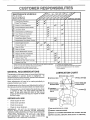
6 • Not required it equtpped wilt_ maintenance-free
battery'
7 - Tighten front axle pivot bolt to 35 It -Ibs maximum
Do not overttghten
Some adjustments will need to be made periodically to
properly maintain your tractor.,
,,
----:
_'
...................
_
The warranty on this tractor does not cover items that have
been subjected to operator abuse or negligence.
To
receive full value from the warranty, operator must maintain
tractor as instructed in this manual..
o
........:
6,_2
RECOMMENDATIONS
EACH
:
6#42
Change more alton when operating under a heavy load or in high ambient temperatures
Service more often when operating in dirty or dusty conditions
If equipped with oil filter, change oJI every 50 hours
Replace blades more often when mowing in sandy soil
BEFORE
t
6#_1,2
.................................
Replace
GENERAL
........
_/2
"Rep'i 'ace Fuel Filter _
I
2
3
4
.........
(_)CHECKiADD
TRANSAXLE
oil level.
FLUID
pressure
_.._
(
L_
for loose fasteners.
IMPORTANT:
DO NOT OIL OR GREASE THE PIVOT
POINTS WHICH HAVE SPECIAL
NYLON BEARINGS.
VISCOUS LUBRICANTS
WILL ATTRACT DUST AND DIRT
THAT
WILL
SHORTEN
THE LIFE OF THE
SELFLUBRICATING
BEARINGS.
1F YOU FEEL THEY MUST
BE LUBRICATED,
USE ONLY A DRY, POWDERED
GRAPHITE TYPE LUBRICANT
SPARINGLY.
(DSAE
30 MOTOR OIL API _ SF/SG
(_GENERAL
PURPOSE
(_ REFER TO CUSTOMER
(_)SPRAY
16
SILICONE
GREASE
RESPONSIBILITIES
LUBRICANT
"ENGINE"
SECTION
(MOVE BOOTS TO LUBRICATE)
CUSTO
E
ESPONSMBmL
ES
TRACTOR
°
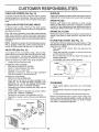
Always observe safety rules when performing any maintenance.
The blade can be sharpened with a file or on a gfinding
wheel. Do not attempt to sharpen while on the mower.
o
To check blade balance, you will need a 5/8" diameter
steel bolt, pin, or a cone balancero (When using a cone
balancer, follow the instructions supplied with bal-
BRAKE
OPERATION
ancer)o
If tractor requires more than six (6) feet stopping distance
at high speed in highest gear, then brake must be adjusted.
(See "TO ADJUST BRAKE" in the Service and Adjustments section of this manua0.
°
TIRES
•
Maintain proper air pressure in all tires (See "PRODUCT SPECIFICATIONS" on page 3 of this manual).
.
Keep tires free of gasoline, oil, or insect control chemicals which can harm rubber,
Slide blade on to an unthreaded portion of the steel bolt
or pin and hold the bolt or pin parallel with the ground.
If blade is balanced, it should remain in a horizontal
position° If either end of the blade moves downward,
sharpen the heavy end untit the blade is balanced°
NOTE: Do not use a nail for balancing blade_ The lobes of
the center hole may appear to be centered, but are noL
CENTER
HOLE
Avoid stumps, stones, deep ruts, sharp objects and
other hazards that may cause tire damage.
BLADE
CARE
For best results mower blades must be kept sharp,
place bent or damaged blades
BLADE
•
•
BLADE
5t8" BOLT
OR PIN
REMOVAL
Re-
(See Fig. 11)
Raise mower to highest position to allow access to
blades.
FIG. 12
Remove hex bott, lockwasher and flat washer securing
blade.
V-BELTS
Install new or resharpened blade with trailing edge up
towards deck as shown.
Check V-belts for deterioration and wear after 100 hours
and replace if necessary, The belts are not adjustable,,
Replace belts if they begin to slip from wear°
Reassemble hex bolt, lock washer and flat washer in
exact order as shown
TRANSAXLE
•
Tighten bolt securely (30-35 FL Lbs. torque)°
IMPORTANT: BLADE BOLT IS GRADE 8 HEATTREATED
Keep transaxie free from build-up of dirt and chaff which
can restrict cooling,
NOTE: We do not recommend sharpening blade - but ifyou
do, be sure the blade is balanced.
CHECK TRANSAXLE
(See Fig. 13)
MANDREL
ASSEMBLY
BLADE
_.
/
LOCKWASHER.
/
HEX BOLT
(GRADE
OIL LEVEL
°
Block up rear axle securely,
°
Remove left rear wheel by removing hub bolts.
°
Remove filler plug from transaxle. Oil level must be
even with plug threads. If necessary, fill with SAE 30
motor oil, API-SF or SG. Replace filler plug,
Reassemble wheel to hub.
TRAILING
EDGE UP
FLAT WASHER,,,
COOLING
*
o
For approximate capacity see "PRODUCT SPECIFICATIONS" on page 3 of this manual.,
8)*__
TRANSAXLE
PLUG
*A GRADE B HEAT TREATED BOLT CAN BE
IDENTIFIED
BY SIXLINESON THE BOLT HEAD,
O
o
O
FIG.11
O
TO SHARPEN
BLADE
(See Fig. 12)
Care should be taken to keep the blade balance&
An
unbalanced blade will cause excessive vibration and eventual damage to mower and engine,
FIG. 13
17
IL
CUSTOM
E
BATTERY
TO CHANGE ENGINE OIL (See Figs. I4 and 15)
Your tractor has a battery' charging system which is sufficient for normal use. However, periodic charging of the
battery with an automotive charger will extend its fife,
Determine temperature range expected before oil change,,
All oH must meet AP1 service Ciassification SF or SGo
o
Be sure tractor [s on level surface,
•
Keep battery and terminals clean.
o
Keep battery bolts tight.
.
o
Oil will drain more freely when warm.
Catch oil in a suitable container.
o
Keep small vent holes open.
o
o
Recharge at 6-10 amperes for 1 hour,
Remove oil fill cap/dipstick. Be careful not to allow dirt
to enter the engine when changing oil,
TO CLEAN BATTERY AND TERMINALS
o
Remove drain plug.
Corrosion and dirt on the battery and terminals can cause
the battery to "leak" power,
o
After oil has drained completely,
and tighten securely_
°
Remove terminal guard,
°
Disconnect BLACK battery cable first then RED battery cable and remove battery from tractor_
o
Rinse the batter./with
=
Clean terminals and battery cable ends with wire brush
until bright.
o
Coat terminals with grease or petroleum jelly.
°
Reinstall battery (See "CONNECT
Assembly section of this manual).
replace oil drain plug
Refill engine with oil through oil fill dipstick tube. Pour
slowly. Do not overfill. For approximate capacity see
"PRODUCT SPECIFICATIONS"
on page 3 of this
manual.
plain water and dry.
Use gauge on oil fill cap/dipstick for chectdng level.
Insert dipstick intothe tube and rest the oil fill cap on the
tube, {3o not thread the cap onto the tube when taking
reading
Keep oil at"FULL" line on dipstick. Tighten
cap onto the tube securely when finished.
BATTERY" in the
ENGINE
LUBRICATION
Only use high quality detergent oif rated with API service
classification SF or SG. Select the oil's SAE viscosity grade
according to your expected operating temperature,,
NOTE: Although multFviscosity oils (5W30, 10W30 etc.)
improve starting in cold weather, these multi-visc6sity oils
wilt result in increased oil consumption when used above
32°F, Check your' engine oil level more frequently to avoid
possible engine damage from running low on oil,
Change the oil after the first two hours of operation and
every 50 hours thereafter or at least once a year if the
tractor is not used for 50 hours in one year.
AIR
SCREEN
FIG, 15
Check the crankcase oil level before starting the engine
and after each eight (8) hours of operation. Tighten oil fill
cap/dipstick securely each time you check the oil level.
SAE VISCOSITY GRADES
°F
*20 °
°c-3oo
0"
30_
-=o_ .10o
328
40 _
oo
"TEMPERATURERANGEANTTClPATED
60 _
_oo
80_
2oo
OIL FILL
CAPIDIPSTICK
100 _
3oo .oo
BEFORENEXTOILCHANGE'
FIG. 14
18
OIL DRAIN
PLUG
,
ii
i
i .....
i
i
CUSTOME
CLEAN
AIR SCREEN
ESPON
MUFFLER
(See Fig. 15)
Inspect and replace corroded muffler and spark arrester (if
equipped) as it could create a fire hazard and/or damage_
Air screen must be kept free of dirt and chaff to prevent
engine damage from overheating.. Clean with a wire brush
or compressed air to remove dirt and stubborn dried gum
fibers
CLEAN
AIR INTAKEtCOOLING
SPARK
PLUGS
Replace spark plugs at the beginning of each mowing
season or after every 100 hours of operation, whichever
comes first. Spark plug type and gap setting are shown in
"PRODUCT SPECIFICATIONS" on page 3 of this manual
AREAS
To insure proper cooling, make sure the grass screen,
cooling fins, and other external surfaces of the engine are
kept clean at all times_
ENGINE OIL FILTER
Every 100 hours of operation (more often under extremely
dusty, dirty conditions), remove the blower housing and
other cooling shrouds.. Clean the cooling fins and external
surfaces as necessary. Make sure the cooling shrouds are
reinstalled.
Replace the engine oil filter every season or every other oit
change if the tractor is used more than 100 hours in one
year.
NOTE: Operating the engine with a blocked grass screen,
dirty or plugged cooling fins, and/or cooling shrouds removed will cause engine damage due to overheating..
The fuel filter should be replaced once each season. If fuel
filter becomes clogged, obstructing fuel flow to carburetor,
replacement is required°
°
With engine cool, remove filter and plug fuel line
sections.
AIR FILTER
IN-LINE
(See Fig. 16)
°
Your engine will not run properly using a dirty air filter.
Clean the foam pre-cleaner after every 25 hours of operation or every season.. Service paper cartridge every 100
hours of operation or every season, whichever occurs first.
Service air cleaner more often under dusty conditions.
o
Loosen knob and remove cover
TO
o
°
°
o
°
°
FUEL FILTER
(See Fig. 17)
Place new fuel filter in position in fuel line with arrow
pointing towards carburetor.
Be sure there are no fuel line leaks and clamps are
properly positioned_
Immediately wipe up any spilled gasoline°
SERVICE PRE-CLEANER
Slide foam pre-cteaner off cartridge.
Wash it in liquid detergent and water.
Squeeze it dry in a clean cloth°
Saturate it in engine oil. Wrap it in clean, absorbent
cloth and squeeze to remove excess oil°
TO SERVICE CARTRIDGE
o
Remove nut and cartridge plate.
°
Gently tap the flat side of the paper cartridge to dislodge dirt.. Do not wash the paper cartridge or use
pressurized air, as this will damage the cartridge.
Replace a dirty, bent, or damaged cartridge_
•
Reinstall the pre-cleaner (cleaned,and oiled) over the
paper cartridge
•
Check rubber seal for damage and proper position
around stud Replace if necessary.
•
Reassemble air cleaner, cartridge plate, and nut.
•
Reinstall air cleaner cover and secure by tightening
knob..
FIG, 17
CLEANING
CARTRIDGE
PLATE
\-.
_.
":_.'.ql.
FOAM_\_
ttl NIJ
J_
!
SEAL
.OT
FIG. 16
Clean engine, battery, seat, finish, etc. of all foreign
matter.
•
Keep finished surfaces and wheels free of all gasoline,
oil, etco
°
Protect painted surfaces with automotive type wax.
We do not recommend using a garden hose to clean your
tractor unless the electrical system, muffler, air filter and
carburetor are covered to keep water out. Water in engine
can result in a shortened engine life
PRE-CLEANER
CARTRIDGE
-
19
SERVICE AN
CAUTION:
o
°
=
o
o
o
ADJUSTMENTS
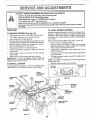
BEFORE PERFORMING ANY SERVICE OR ADJUSTMENTS:
Depress clutch/brake pedal fully and set parking brake.
Place gearshift lever in neutral (N) position,
Place attachment clutch in "DISENGAGED"
position.
Turn ignition key "OFF" and remove key,
Make sure the blades and all moving parts have completely stopped.
Disconnect spark plug wire from spark plug and place wire where it cannot come in contact
with plug.
TRACTOR
TO REMOVE
TO LEVEL MOWER
MOWER
Adjust the mower while tractor is parked on level ground or
driveway.
Make sure tires are properly inflated (See
"PRODUCT SPECIFICATIONS" on page 3 of this manual),
if tires are over or' underinflated, you will not properly adjust
your mowen
SIDE-TO-SIDE ADJUSTMENT (See Figs. 18 and 19)
o
Raise mower to its highest position,.
o
Measure height from bottom of deck curl to ground
level at front corners of mower. Distance "A" on both
sides of mower should be the same.
(See Fig. 18)
o
°
o
o
Place attachment clutch in "DISENGAGED" position,
Turn height adjustment knob to lowest setting.
Lower mower to its lowest position,,
Remove retainer spring holding anti-swaybar to chassis bracket and disengage antFswaybar from bracket,.
o
Remove retainer springs from suspension arms at
deck and disengage arms from deck,.
°
Raise attachment lift to its highest position°
°
Remove two retainer'springs from each front link and
remove links.
•
Slide mower forward and remove belt from electric
clutch pulley,,
•
Slide mower out from under right side of tractor.,
IMPORTANT: tFAN ATTACHMENT OTHER THAN THE
MOWER DECK IS TO BE MOUNTED ON THE TRACTOR,
REMOVE THE FRONT LINKS,
TO INSTALL
o
o
=
Follow procedure described in "INSTALL MOWER AND
DRIVE BELT" ir_the Assembly' section of this mariuaL
SUSPENSION
ARMS
NUTS
BOTTOM
OF CURL
FRONT
SUSPENSION
BRACKET
LIFT
LINKS
If adjustment is necessary, make adjustment on one
side of mower only..
To raise one side of mower, tighten rift link adjustment
nut on that side,
To lower one side of mower, loosen lift link adjustment
nut on that side.
NOTE: Each full turn of adjustment nut wilt change mower
height about 3/16".
•
Recheck measurements after adjusting..
MOWER
ADJUSTMENT
HOUSING
BOTTOM
OF CURL
"A"--_
'A
\
FIG. 19
FRONT MOWER
BRACKET
ELECTRIC
CLUTCH
PULLEY
CHASSIS
FRONT
SUSPENSION
BRACKET
RETAINER
SPRINGS
MOWER
BRACKET
RETAINER
SPRING
ANTI-SWAY
BAR
RETAINER
SPRINGS
FIG. t8
2O
SERVICE A
ADJUSTMENTS
TO REPLACE
FRONT-TO-BACK ADJUSTMENT (See Figs, 20 and 2!) IMPORTANT: DECK MUST BE LEVEL SIDE-TO-SIDE. IF
THE FOLLOWING FRONT-TO-BACK ADJUSTMENT IS
NECESSARY, BE SURETO ADJUST BOTH FRONT LINKS
EQUALLY SO MOWER WILL STAY LEVEL SIDE-TO-SIDE.
To obtain the best cutting results, the mower housing
should be adjusted so the front is approximately 1/8" to 1/2"
lower than the rear when the mower is in its highest
position.
Check adjustment on right side of tractor. Measure distance "F" directly in front of and behind the mandrel at
bottom edge of mower housing as shown.,
•
Before making any necessary adjustments, check that
both front links are equal in length,
°
If links are not equal in length, adjust one link to same
length as other link,,
•
To lower front of mower housing, loosen nut"G"on both
front links an equal number of turns
.
When distance "F" is 1/8" to 1/2" lower at front than
rear, tighten nut "H" against trunnion on both front links.
°
To raise front of mower housing, loosen nut "H" from
trunnion on both front links,, Tighten nut "G" on both
front links an equal number of turns°
o When distance "F" is 1/8" to 1/2" lower at front than
rear, tighten nut "H" against trunnion on both front
links.
NOTE: Each full turn of nut "G" will change dim,, "F" by
approximately 3!8".
°
Recheck side-to-side adjustment.,
MOWER
DRIVE
BELT
MOWER DRIVE BELT REMOVAL (See Fig, 22) °
Park tractor on a level surface., Engage parking brake,
o
Remove four screws from L.H_ mandrel cover and
remove cover,
o
Roll belt over the top of LHo mandrel pulley,
o
Remove belt from electric clutch pulley°
°
Remove belt from idler pulleys,
.
Remove any dirt or grass clippings which may have
accumulated around mandrels and entire upper deck
surface.
•
Check primary idler arm and two idlers to see that they
rotate freely,
•
Be sure spring is securely hooked to primary idler arm
and bolt in mower housing,,
MOWER DRIVE BELT INSTALLATION (See Fig,, 22) *
•
Install belt in both idlers° Make sure belt is in both belt
keepers at the idlers as shown°
•
Install new belt onto electric clutch pulley°
°
Roll belt into upper groove of L,,H, mandrel putley_
•
Carefully check belt routing making sure belt is in the
grooves correctly and inside belt keepers,
Reassemble L,H_ mandrel cover,,
.
SPRING
L°H,
MANDREL
COVER
SCREWS
IDLER
PULLEYS
ELECTRIC
CLUTCH
PULLEY
PRIMARY
IDLER ARM
FIG. 2O
BOTH FRONT LINKS SHOULD
BE EQUAL IN LENGTH
BOLT IN
MOWER
HOUSING
MANDREL
MOWER
DRIVE
BELT
BELT
KEEPERS
NUT "G"
FIG. 22
NUT "H"
FRONT LINKS
FIG. 21
21
SERVICE AND ADJUSTMENTS
TO REPLACE
(See Fig. 23)
MOWER
BLADE
DRIVE
o
Make sure attachment clutch and ignition switches are
in "OFF" position.,
°
Adjust the three nylon Iocknuts until space between
clutcti plate and rotor measures .012" at all three slot
locations cut in the inside of brake plate.
NOTE: After instafling a new electric clutch, run tractor at
full throttfe and engage and disengage electric clutch 10
cycles to wear in clutch plate_
BELT
Park the tractor on level surface,, Engage parking brake.
•
Remove mower drive belt (See''TO REPLACE MOWER
DRIVE BELT" in this section of this manual).
°
o
Remove mower (See "TO REMOVE MOWER" in this
section of this manual)
Remove four screws from RH.. mandrel cover and
remove cover. Unhook spring from bolt on mower
housing°
°
Carefully roll belt off R.H_ mandrel pulley.
-
Remove belt from center mandrel pulley, idter pulley,
and LH. mandrel pulley.
°
Remove any dirt or grass which may have accumulated around mandrels and entire upper' deck surface.
o
Check secondary idler arm and idler to see that they
rotate freely_
o
Be sure spring is hooked in secondary idler arm and
sway-bar bracket,
°
Instal! new belt in lower groove of L.H.; mandrel pulley,
idler pulley, and center mandrel pulley as shown.
°
Roll belt over R.Ho mandrel pulley° Make sure belt is in
all grooves properly.
°
Reconnect spring to bolt in mower housing and reinstall RH. mandrel cover'.
°
Reinstall mower to tractor (See "INSTALL MOWER
AND DRIVE BELT" in the Assembly section of this
manual)_
o
Reassemble mower drive belt (See "TO REPLACE
MOWER DRIVE BELT" in this section of this manual)°
L,,H,,MANDREL
MOWER BLADE
CLUTCH
SLOT
.0t2"
)
BRAKE PLATE
NYLON LOCKNUT (3)
FIG. 24
TO ADJUST
BRAKE
(See Fig. 25)
Your tractor is equipped with an adjustable brake system
which is mounted on the left side of the transaxle.
If tractor requires more than six (6) feet stopping distance
at high speed in highest gear, then brake must be adjusted_
CENTER
"_,
PLATE
MANDREL
R_H_
MANDREL
COVER
°
Depress clutch/brake pedal and engage parking broke.
=
Measure distance between brake operating arm and
nut "A" on brake rod.
o
If distance is other' than 1-3/4", loosen jam nut and turn
nut "A" until distance becomes 1-3/4'L Retighten jam
nut against nut "A"o
°
Road test tractor for'proper' stopping distance as stated
above_ Readjust if necessary. If stopping distance is
still greater than six (6) feet in highest gear, further
maintenance is necessary° Contact your nearest authorized service center/department
WITH PARKING BRAKE "ENGAGED"
IDLER ARM
NUT "A"
/
SWAY BAR
BRACKET
IDLER
_?,';_t}
PULLEY
\
\
FIGo 23
AM NUT
TO ADJUST
ATTACHMENT
CLUTCH
(See Fig. 24)
The electric clutch should provide years of service. The
clutch has a built-in brake that stops the pulley within 5
seconds._ Eventually, the internal brake will wear which
may cause the mower blades to not engage, or, to not stop
as required Adjustments should be made by your nearest
authorized service centerldepartment.
®
FIG, 25
22
SERVHCE AN
TO REPLACE
(See Fig. 26)
MOTION
FRONT
DRIVE BELT
Park the tractor on level surface. Engage parking brake.
For ease of service there is a belt installation guide decal on
bottom of left footrest. It is not necessary to remove mower,
•
BELT REMOVAL Engage parking brake (creates slack in belt)o
o Remove mower drive belt from electric clutch pulley
only (See "TO REPLACE MOWER DRIVE BELT" in
this section of this manual).
°
Roll motion drive belt off transaxle pulley.
°
Roll belt off clutching idler pulleys, then off engine
pulley and front V-idler pulley.
•
Pull belt out of al! belt keepers,
BELT INSTALLATION -
WHEEL
ADJUSTMENT
TO ADJUST TOE-IN (See Figs, 27 and 28) •
Loosen jam nuts at adjustment sleeves on tie rod.
•
Adjust tie rod until dimension "A" is 1/8" to 1/4" less than
dimension "B".
Place V part of belt into grooves on engine pulley and
front V-idler, making sure to route belt inside of belt
keepers.
°
Put belt coming from V-idler above midspan belt keeper,
then onto clutching idler pulleys as shown
°
Make sure V part of belt engages V-idler.
°
Place belt around transaxle pulley, beginning at top.
V part of belt should engage transaxle pulley.
•
Place long lower section of belt through loop in midspan
belt keeper.
.
Check to be sure belt is on proper side of all belt
keepers°
°
Reinstall mower drive belt onto electric clutch pulley.
IMPORTANT; CHECK BRAKE ADJUSTMENT.
STEERING
TOE-IN
TO CHECK TOE-IN (See Fig. 27) °
Position front wheels straight ahead,
•
Measure distance between wheels at front and rear of
tires (dimensions "A" and "B")_
•
Front dimension "A" should be 1/8" to 1/4" tess than
rear dimension "B".
•
TO ADJUST
WHEEL
Front wheel toe-in is required for proper steering operation
Toe-in was set at the factory and adjustment should not be
necessary. If parts in the front axle or steering mechanism
have been replaced or damaged, check toe-in and adjust
if necessary,r
•
Tighten jam nuts securely.
FRONT WHEEL
CAMBER
The front wheel camber is not adjustable on your tractor. If
damage has occurred to affect the front wheel camber,
contact your nearest authorized service center/department.
ALIGNMENT
If steering wheel crossbars are not horizontal (left to right)
when wheels are positioned straight forward, remove steering wheel and reassemble per instructions in the Assembly
section of this manual
FIG. 27
TRACTOR V-BELT DRIVE SCHEMATIC
VIEWED FROM Loll. SIDE OF TRACTOR
CLUTCHING
IDLER
ADJUSTMENT
SrEEVES
JAM
NUTS
BELT
CLUTCHING
FLATIDLER
ENGINE
PULLEY
ABOVE
V-IDLER
JAM
NUTS
FIG. 28
_3
BELT
TWISTS
BELT
KEEPER
TRANSAXLE
PULLEY
AS VIEWED FROM BOTTOM
FIG. 26
23
...............
................
_nl,lll
ii
ii
SERVHOE AND ADJUSTMENTS
,
TO REMOVE
WHEEL
i
u,nrm
I ii
........
i, ,u'lm,',
FOR REPAIRS
FRONT WHEEL (See Fig. 29) o Block up axle secure¥
.
Remove axlecover, retaining ring and washers to allow
wheel removal
o
.
Repair tire and reassemble,,
Replace washers and snap retaining ring securely in
axle groove,,
Replace axle cover_
"POSITIVE"
............
(+)
"NEGATIVE"
ii ill,,,i,
(-)
....................
O
L.
H,
PANEL
BOLT
WASHERS
RETAINING
AXLE
COVER
FIG. 30
FIG. 29
TO REPLACE
REAR WHEEL o Block rear axle securely
°
Remove five (5) hub bolts to atlow wheel removal.
o
Repair tire and reassemble, Replace and tighten hub
bolts securely,
o
o
o
°
TO START ENGINE WITH A WEAK BATTERY
(See Fig. 30)
HEADLIGHT
BULB
Raise hood,
Pull bulb holder out of the hole in the backside of the
grill
Replace bulb in hoider and push bulb holder securely
back into the hole in the backside of the grill,,
Close hood_
INTERLOCKS
AND RELAYS
Loose or damaged wiring may cause your tractor tO run
poorly, stop running, or prevent it from starting.
= Check wiring° See electrical wiring diagram in Repair
Parts section of this manual
CAUTION: Lead-acid batteries generate explosive gases. Keep sparks, flame
and smoking materials away from batterieso Always wear eye protection
when around batteries.
=•
TO REPLACE
FUSE
Replace with 30 amp autornotive-type plug-in fuse_ 'The
fuse holder is located behind the dash.
If your' batter:/is
too weak to start the engine, it should be
recharged
If "jumper cables" are used for emergency
starting, follow this procedure:
IMPORTANT:
YOUR TRACTOR IS EQUIPPED WITH A t2
VOLT NEGATIVE
GROUNDED
SYSTEM°
THE OTHER
VEH1CLE
MUST
ALSO
BE A 12 VOLT
NEGATIVE
GROUNDED
SYSTEM.
DO NOT USE YOUR TRACTOR
BATTERY TO START OTHER VEHICLES
TO ATTACH JUMPER CABLES o Connect each end of the RED cable to the POSITIVE
(+) terminai of each battery, taking care not to short
against chassis,
o Connect one end of the BLACK cable to the NEGATIVE (-) terminal of fully charged battery_
= Connect the other end of the BLACK cable to a panel
bolt on the left side of the tractor, away from fuet tank
and battery..
TO REMOVE CABLES, REVERSE ORDER °
BLACK cable first from chassis and fully charged
battery.
*
RED cable last from both batteries.
24
i,ii,.111_lll
i,,llllii,ll,
$.ERVICE AN
, ,, ii,, LI........
ADJ
$TMENT$
,,rlrl ii
TO ADJUST ATTACHMENT
LIFT SPRING
: i
i,, i,
ii i
,,
(See Fig, 31)
TO REMOVE HOOD AND GRILL
(See Fig. 32)
o
While holding spring bushing with wrench, loosen jam
nut.
-,
Raise hood_
°
Turn adjustment bolt clockwise to extend spring and
reduce lift effort for heavier attachments..
°
Unsnap headlight wire connector.
o
Stand in front of tractor,. Grasp hood at sides, tilt toward
engine and lift off of tractor.
•
To repFace, reverse above procedure.
o
Turn adjustment
tachments..
°
Retighten
bolt counterclockwise
jam nut against
spring
for lighter at-
ASSEMBLY
bushing.
IMPORTANT:
DO NOT ADJUST FOR MAXIMUM SPRING
TENSION WHEN USING LIGHT ATTACHMENTS
SUCH
AS A MOWER,, ADJUST LIFT LEVER SPRING TO AID IN
LIFTING ATTACHMENT,
DO NOT OVERPOWER SPRING.
WHEN REMOVING
ATTACHMENT,
ALWAYS
ADJUST
SPRING TENSION TO iTS LOWEST POSITION,
ADJUSTMENT
BOLT
HEADLIGHT
WIRE
CONNECTOR
SPRING RUSHING
ATTACHMENT
LIFT SPRING
JAM NUT
°
o
o
oJ
FIG, 32
FIG. 3'I
25
TO ADJUST CHOKE CONTROL
(See Figs. 33 and 34)
ENGINE
TO ADJUST
THROTTLE
(See Fig, 33)
CONTROL
CABLE
The choke control has been preset at the factory and
adjustment should not be necessary, check adjustment as
described below before loosening cable. If adjustment is
necessary, proceed as follows:
The throttle control has been preset at the factory and
adjustment should not be necessary Check adjustment as
described below before loosening cable If adjustment is
necessary, proceed as follows:
o
With engine not running, move choke control (located
on dash panel) to full choke (N) position.
Remove air cleaner cover, filter and cartridge plate to
expose carburetor choke (See "AIR FILTER" in the
Customer Responsibilities section of this manual)°
Choke should be closed
If it is not, loosen casing
clamp screw and move choke cable until choke is
completely closed+ Tighten casing clamp screw se+
curefy+
Reassemble air cleaner.
o
With engine not running, move throttle control lever to
fast (._) position°
°
o
Checkthat speed control lever is against stop screw. If
it is not, loosen casing clamp screw and pull throttle
cable until lever is against screw. Tighten clamp screw
securely.
.
IDLE FUEL
ADJUSTING
SCREW
°
IDLE SPEED
ADJUSTING
SCREW
CLOSED FOR
THROTTLE
CONTROL
CABLE
/
FIG. 34
STOP
SCREW
I
CLAMP
SCREW
CHOKE
CONTROL
CABLE
FIG. 33
26
SERVICE AND ADJUSTMENTS
TO ADJUST
CARBURETOR
(See
Fig. 33)
The carburetor has been present at the factory and adjustment should not be necessary° However, minor adjustment
may be required to compensate for differences in fuel,
temperature, altitude or load. If the carburetor does need
adjustment, proceed as follows:
In general, turning the adjusting needles in (clockwise)
decreases the supply of fuel to the engine giving a leaner
fuel!air mixture° Turning the adjusting needles out (counterclockwise) increases the supply of fuel to the engine
giving a richer fuel/air mixture.
IMPORTANT:
DAMAGE TO THE NEEDLES AND THE
SEATS tN CARBURETOR MAY RESULT IF SCREW IS
TURNED IN TOO TIGHT
PRELIMINARY SETTING o
Be sure you have a clean air filter, and the throttle
control cable is adjusted properly (see 'q'o ADJUST
THROTTLE CONTROL CABLE" in the Service and
Adjustments section of this manual).
•
With engine off turn idle fuel adjusting needle in (clockwise) closing it finger tight and then turn out (counterclockwise) 1 turn_
FINAL SETTING •
Start engine and allow to warm for five minutes. Make
final adjustments with engine running and shift!motion
control lever in neutral (N) position.
•
The high idle is set at the factory and cannot be
adjusted°
o
!d!e speed setting - With throttle control lever in slow
(._)
position, engine should idle at 1200 RPMo If
engine idles too slow or fast, turn idle speed adjusting
screw in or out until correct idle is attained.
o
Idle fuel needle setting - With throttle control lever in
slow (,_) position, turn idle fuel adjusting needle in
(clockwise) until engine speed decreases and then
turn out (counterclockwise) approximately 3/4 turn to
obtain the best low speed performance.
°
Recheck idle speed_ Readjust if necessary..
ACCELERATION TEST_
o
Move throttle control lever from slow (,_) to fast
position. If engine hesitates or dies, turn idle
adjusting needle out (counterclockwise) 1/8 turn.
peat test and continue to adjust, if necessary,
engine accelerates smoothly,
(,_)
fuel
Reuntil
High speed stop isfactory adjusted.. Do not adjust*damage
may result.
IMPORTANT;
NEVER TAMPER WITH THE ENGINE
GOVERNOR, WHICH IS FACTORY SET FOR PROPER
ENGINE SPEED, OVERSPEEDING THE ENGINE ABOVE
THE FACTORY HIGH SPEED SETTING
CAN BE
DANGEROUS.' IF YOU THINKTHE ENGINE-GOVERNED
HIGH SPEED NEEDS ADJUSTING, CONTACT YOUR
NEAREST
AUTHORIZED
SERVICE
CENTER!
DEPARTMENT, WHICH HAS PROPER EQUIPMENT AND
EXPERIENCE
TO
MAKE
ANY
NECESSARY
ADJUSTMENTS
27
STORAGE
ENGmNE
immediately prepare your tractor for storage at the end of
the season or if the tractor will not be used for 30 days or
more°
.................
................
FUEL SYSTEM
i i i,ll,,1
IMPORTANT:
IT IS IMPORTANT TO PREVENT GUM
DEPOSITS FROM FORMING IN ESSENTIAL
FUEL
SYSTEM PARTS SUCH AS CARBURETOR, FUEL FILTER,
FUEL HOSE, OR TANK DURING STORAGE.
ALSO,
EXPERIENCE INDICATES THAT ALCOHOL BLENDED
FUELS (CALLED GASOHOL OR USING ETHANOL OR
METHANOL) CAN ATTRACT MOISTURE WHICH LEADS
TO SEPARATION AND FORMATION OF ACIDS DURING
STORAGE.
ACIDIC GAS CAN DAMAGE THE FUEL
SYSTEM OF AN ENGINE WHILE IN STORAGE..
o Drain the fuel tank,
CAUTION: Never store the tractor with
gasoline in the tank inside a building
where fumes may reach an open flame
or' spark. Allow the engine to cool
before storing in any enclosure°
TRACTOR
Remove mower from tractor for winter storage.. When
mower is to be stored for a period of time, clean it thoroughty, remove all dirt, grease, leaves, etc. Store in a
clean, dry area..
o
Clean entire tractor (See"CLEANING" in the Customer
Responsibilities section of this manual).
o
Inspect and replace belts, if necessary (See belt replacement instructions in the Service and Adjustments
section of this manual)..
•
Lubricate as shown in the Customer Responsibilities
section of this manual.
-
Be sure that all nuts, bolts and screws are securely
fastened. Inspect moving parts for damage, breakage
and wear. Replace if necessary_
-
Touch up all rusted or chipped paint surfaces; sand
lightly before painting.
o
•
,,
NOTE:
Fuel stabilizer is an acceptable alternative in
minimizing the formation of fuel gum deposits during storage,. Add stabilizer to gasoline in fuel tank or storage
container. Always follow the mix ratio found on stabilizer
container. Run engine at least 10 minutes after adding
stabilizer to allow the stabilizer to reach the carburetor. Do
not drain the gas tank and carburetor if using fuel stabilizer_
ENGINE
Fully charge the battery forstorage.
•
Affera period of time in storage, battery may require
recharging.
o
•
OIL
Drain oil (with engine warm) and replace with clean engine
oil. (See "ENGINE" in the Customer Responsibilities
section of this manual),
BATTERY
o
Start the engine and let it run until the fuel lines and
carburetor are empty.
Never use engine or carburetor cleaner products in the
fuel tank or permanent damage may occur.
Use fresh fuel next season,,
CYLINDERS
To help prevent corrosion and power leakage during
long periods of storage, battery cables should be
disconnected and battery cleaned thoroughly (see "TO
CLEAN BATTERY AND TERMINALS" in the Customer Responsibilities section of this manual).
After cleaning, leave cables disconnected and place
cables where they cannot come in contact with battery
terminals.,
°
°
Remove spark plug(s).
Pour one ounce of oil through spark plug hole(s) into
cylinder(s).
o
Turn ignition key to "START" position for a few seconds
to distribute oil.
•
Replace with new spark plug(s).
OTHER
°
Be sure battery drain tube is securely attached.
°
Do not store gasoline from one season to another..
°
if battery is removed from tractor for storage, do not
store battery directly on concrete or damp surfaces,.
•
Replace your gasoline can if your can starts to rust.
Rust and/or dirt in your gasoline will cause problems.
°
If possible, store your-tractor indoors and cover it to
give protection from dust and dirt.
°
Cover your tractor with a suitable protective cover that
does not retain moisture. Do not use plastic, Plastic
cannot breathe which allows condensation to form and
will cause your tractor to rust.
IMPORTANT: NEVER COVER TRACTOR WHILE ENGINE
AND EXHAUST AREAS ARE STILL WARM.
28
TROUBLESHOO=['mNG
i i i,,i,ii,,,
POINTS
i i i i,ill,,,in,i
CORRECTION
PROBLEM
CAUSE
Will not start
1
Out of fuel
2
3
4
5,
6
7,
Engine not "CHOKED"
Engine f!ooded
Bad spark piug
Dirty air filter
Dirty fuel filter.
Waterin fuel
lr
Fill fuel tank,
properly
2,
3,
4
5,
6
7,
See "TO START ENGINE" in Operation section
Wait several minutes before attempting to start
Replace spark plug
Clean!replace air filter,
Replace fuel filter.
Drain fuel tank and carburetor, refill tank with fresh
8,
9
10
Loose or damaged wiring
Carburetor out of adjustment.
Engine valves out of adjustment
8
9
10
gasoline and replace fuel filter,
Check all wiring
Contact an authorized service centerldepartment,
Contact an authorized service center/department.
Hard to start
1
2
3.
4.
5.
6
7
8
Dirty air filter
Badspark plug
Weak or dead battery
Dirty fuel filter,
Stale ordirty fuel
Loose or damaged wiring,
Carburetor out of adjustment
Engine valves out of adjustment
1,
2,
3
4
5
6
7
8
Clean/replace air filter,
Replace spark plug,
Recharge or replace battery,
Replace fuel filter
Drain fuel tank and refill with fresh gasoline
Checkalf wiring
Contact an authorized service center/department.
Contact an authorized service center/department,
Engine will not turn over
t,
2
3
4
Clutch!brake pedalnot depressed
Attachment clutchis engaged
Weak or dead battery
Blown fuse
5
6,
7,
8,
9,
Corroded battery terminals
Loose or damaged wiring.
Faulty ignition switch,
Faultysoleno{d orstarter
Faulty operator presence switch(es)
1,
2
3
4,
5,
6,
7
8,
9,
Depress clutch/brake pedal,
Disengage attachment clutch
Recharge or replace battery
Replace fuse,
Clean battery terminals
Check all wiring,,
Check/replace ignition switch
Check/replace solenoid or starter.
Contact an authorized service centerldepartment
i
_ll n in 'HII
i
................................
, i,_,l,_ll,,,i
i, nlUl,,i
Engine clicks but will not
start
1
2
3
4
Weak or dead battery,
Corroded battery terminals.
Loose or damaged wiring
Faulty solenoid or starter
1
2
3
4,
Recharge or replace battery
Clean battery terminals
Check allwiring
Check/replace solenoid or starter,
Loss of power
1
2
3,
4,
5.
6,
7
8,
9,
Cutting too much grass/too fast,
Throttle in "CHOKE" position
Build-up of grass, leaves and trash under mower,
Dirty air filter_
Low o_1level/dirty oi_
Fauityspark pkJg
DirtyfueI filter
Stale or dirty fuel,
Waterin fuel,
1.
2
3
Set in "Higher Cut" position!reduce speed
Adjust throttte controt
Clean underside of mower housing,
4
5
6,
Clean/replace air filter.
Checkoitlevet!change
oil,
Clean and regap or change spark ptug
7,
8,
9
Replace fuel f{Iter
Drain fuel tank and refilr with fresh gasoline.
Drain fuel tank and carburetor, refill tank with fresh
10
!1
I2
13,
14.,
t5.
_luiiuJiH_
10
11
12,
I3,
14
15,
Spark plug wire _oose.
Dirty engine air screen/fins
Dirty/clogged muffler.
Loose or damaged wiring
Carburetor out of adjustment
Engine vatves out of adjustment
gasoline and replace fuet filter,
Connect and tighten spark plug wire
Clean engine air screen/fins
Cleantreplace muffler
Check alt wiring
Contact an authorized service center/department,
Contact an authorized service centertdepartment
i i i i illl,i,
Excessive vibration
1
2
Worn, bent orfoose blade
Bent blade mandrel,
3.
Loose/damaged
1.
2,
3
part(s)
29
Replace blade Tighten blade bert
Replace blade mandrel
Tighten loose part(s)
Replace damaged
parts,
TROU
LESHOOTING POINTS
i
CORRECTION
CAUSE
PROBLEM
ii
........
Engine continues to run
when operator leaves seat
with attachment clutch
I.
Faulty operator_safety presence control system
1.
..................
..........
i,,II,IH,II,I
.......
Check wiring, switches and connections.
If not
corrected, contact an authorized service center/
department
engaged
Poor cut - uneven
i illl,rl
1.
2.
Worn, bent orloose b]ade_
Mower deck not level
3.
4
Buildup of grass, leaves, and trash under mower.
Bent blade mandrel
5
Clogged mower deck vent holes from buildup of
grass, leaves, and trash around mandrels
t
Obstruction
2
3
4.
Worn!damaged mower drive belt
Frozen idler puIIey.
Frozen blade mandrel
2
3..
4.
Travel speed too fast.
Wet grass
Mower deck notlevel
1
2
3,.
4
5
Replace blade. Tighten blade bolt
Level mower deck.
Clean underside of mower housing
Replace blade mandrel.
Ciean around mandrels to open vent holes
t
2
3
4,
Remove
Replace
Replace
Replace
1
2.
3
4
5
6,
7
Place throttle control in "FAST" position.
Shift toslower speed.
Allow grass to dry before mowing
Level mowerdeck
Check tires for proper air pressure
Replace/sharpen blade Tighten blade bolt,
Clean underside of mower housing
8.
9,
t0
11..
Replace mower drive belt.
Reinstall blades sharp edge down
Replace with btades listed tn this manual
Clean around mandrels to open vent holes.
, ,.,i i,j,i,
Mower blades will not
rotate
in clutch mechanism
Engine speed too stow,
Poor grass discharge
5
6.
7..
8
9
10
tt.
Lowtuneven tire air pressure
Worn, bent or loose blade
Buildup of grass, leaves and trash under mower
Mower drive belt worn,.
Blades improperly installed.
improper blades used,
Clogged mower deck vent holes from buildup of
grass, leaves, and trash around mandrels.
1
Turn switch "ON":
2.
3
4.
5
Replace bulb(s).
Check/replace light switch
Check wiring and connections.
Replace fuse
Bad battery cell(s),
Poor cable connections.,
1
2
Replace battery
Check/clean all connections.
3.
4.
Faulty regulator (if so equipped).
Faulty alternator,
3
4
Replace regulator
Replace altematof,
1
Engine throttle control not set at "SLOW"
position for 30 seconds before stopping engine
1
Move tt';rotttecontrol to "SLOW" position and allow
to idle for 30 seconds before stopping engine,
Headtight(s) not wet Icing
(if so equipped)
1
2.
3
4.
5
Switch is "OFF"
Bulb(s) burned out
Fautty light switch
Loose or damaged wiring
Blown fuse
Battery will not charge
t
2.
............................
Engine "backfires"
when turning engine
"OFF"
obstruction,,
mower drive belt,
idler pulley.
blade mandrel.
i
3O
TRACTOR
- - MODEL NUMBER
917.251551
SCHEMATIC
BATTERY
FUSE 3O AMP
AMMETER
c
G
WHITE
WHITE
!
1
CLUTCH / BRAKE
IGNITION
SWITCH
BLACK
i
BLACK
[]
WHITE
GROUNDING
CONNECTOR
AFTER FIRE SOLENOID
! ...........
(_
IGNITION
_
SPARK _----"_)
UNIT
_
PLUGS
@_-----_}
t
BLUE
SMART SPARK
ELECTRONICS
CHARGING
SYSTEM
I_-
"_)
]
OU':[PUT
t5 AMP DO @ 3600 RPM
\_]
REe,,
REGULATOR
28 VOLTS
AC
O 3600
RPM
(REGULATOR
DISCONNECTED)
METER
_
ENGINE
CONNECTIONS
HOUR
ORANGE
I ......
I
1
l
l
BROWN
HEADLIGHT
O
SWlTCH
NON*REMOVABLE
CONNECTIONS
(OFF)
HEADLIGHTS
GFC
O
TRACTOR
IGNITION SWITCH
"M" FOR ENGINE --,,
SHORTING
_
REMOVABLE
CONNECTIONS
D
OIL SENTRY_
OPTION
(YELLOW WIRE
TO LIGHT PKG.)
PTO SWITCH
CIRCUIT
oFF
'oN'"
CONNECTOR
BA]-rERY
_
/_. CHARGING
_
(RED WIRE)
A
POSITION
ik
c +G
C+
FI,,B + E,A+
D
SW TCHED
+12V
(BLUE
WIRE)
ENGINE
CONNECTOR
REGULATOR-,,
(PURPLE W1RE, \
IGNITION
i
POSITION
OFF
ON
START
SWITCH
CIRCUIT
.............. M + G
B+L
B+ S + L .....
/_,
WIRING INSULATED CLIPS
NOTE: IP WiRiNG INSULATED
CLIPS WERE REMOVED FOR
SERViCiNG OF UNIT, THEY
SHOULD BE REPLACED TO
PROPERLY SECURE YOUR WIRING
31
RED WIRE)
F--ENGINE
//,,SHORTING
I_I(WHITE
CARBURETOR "4z
SOLENOID
(RED WIRE,
BLUE WIRE)
L__J
WIRE)
_"-OIL SENTRY
(GREEN WIRE)
REPAIR PARTS
TRACTOR
-- MODEL NUMBER
917.251551
ELECTRICAL
33
19
32
20
31
20
I
\
46 /
/
/
/
/
\
/
s'
1.i7
7
"/
REPAIR PARTS
TRACTOR
-- MODEL NUMBER
917.251551
ELECTRICAL
KEY
NO.
PART
NO.
1
2
3
4
6
7
8
9
10
11
12
19
20
21
22
24
25
26
28
29
30
31
32
33
34
39
40
41
146141
7476041.2
STD551025
STD551125
STD541025
7697J
7603J
109596X
14521t
145209
145769
STD551125
73350400
136850
4152J
4014J
t46686
108824X
6408R
121305X
144921
140400
141226
140403
I107_2X
109553X
151730
17720408
42
43
45
46
47
49
50
51
53
131563
145673
122822X
110940X
17011008
153249
146283
140405
71031008
54
73951000
NOTE:
DESCRIPTION
Battery
Bolt, Hex !/4-20 x 3/4
Washer 9/32 x 5/8 x 16 G&
Washer, Lock I/4
Nut, Hex 1/4-20
Tube, Drain
Tray, Battery
Clamp, Hose
Bolt, Btr. FrL 1/4-20 x 7-1/2
Holddown Battery Dash Mount
Nut, Push Nylon 1/4 Battery Front
Washer, Lock 1/4
Nut, Hex Jam 1/4-20
Harness, Light Socket W/4152J
Bulb, Headlight
Cable, Battery
Cable Battery
Fuse
Cable, Ground
Switch, Plunger
Switch, Ignition
Nut, Ignition
Cover, Switch Key
Key, Ignition
Sw{tch, Light
Switch Intlk CL MWR Gry 4 Term
Harness, ignition
Screw, Hex Washer Head, Thread
Cutting 1/4-20 x 1/2
Cover, Terminal
Solenoid
Ammeter
Meter, Hour
Screw 10-24 x 1/2 Black
Washer Pinned Delta
Switch, PoToO.
Ring Retainer PTO
Screw, Hex Washer Head
#10-32xl/2
Nut, Keps #10-32
Al! component dimensions given in UoS, inches
1 inch = 25.4 mm
33
REPAIR PARTS
TRACTOR
CHASSIS
-- MODEL NUMBER
917.251551
AND ENCLOSURES
10
14
18
38
/
59
9
15
13
11
92
68
57
48
37
5
j_7120
41
iI
_
68
, @, ,t-,j •
49
, REPAnR PARTS
TRACTOR
CHASSIS
KEY
NO.
- - MODEL NUMBER
917.251551
AND ENCLOSURES
PART
NO.
1 150253
2 140506
3 136671X558
4 73800700
5 145203
6 150273
7 17720408
8 145166
9 108067X
!0
190920I6
11 137270
12 137269
13 137271
14 136673X558
15 136374
16 121794X
17 174906'12
18 136373X428
19 19131312
20 STD523710
21 STD541437
22 136670X558
23 17490616
24 145243X558
28 145244X558
29 145349
30 145051X014
31 145183
32 141315
33 141314
34 142131
35 19111116
36 74780512
37 121642X558
38 19091216
39 136961
DESCRIPTION
Rail, Frame RH
Drawbar, Gt
Panel Asm. Side LH
Nut, Lock Hex 7/16 Unc
Dash, Plastic Black
Dash, Lower Vgt One Piece
Screw, Thd Cut 1/4-20 x 1/2
Support, Battery
Nut, Pal
Washer 9/32 x 1-1/4 x I6 Ga..
Rivet, Ratchet Male
Washer, Nylon
Rivet, Ratchet Female
Hood Asm., Pnt
Lens, Bar Clear
Cover, Access
Screw, Thdroi 3/8-16 x 3/4
Grille
Washer 13/32 x 13/16 x 12 Ga**
Bolt, Fin Hex 3/8-I6 x 1
Nut Crowniock 3/8-16 Unc
PanelAsm, Side RH
ScrewThdrol
3/8-16 x 1 Ty-Tt
Footrest, RH
Footrest, LH
Bracket, Support Dash
Saddle, SIkscr Vgt
Brace, Support Steering
Bracket Asmo, Frame Pivot Lh
Bracket Asm,, Frame Pivot Rh
Bracket, Engine Support Rear
Washer 11/32x11!16x16Ga_
Bolt, Fin Hex 5/16_!8 x 3/4
Fender, Pnto
Washer 9i32x3i4x16Ga.
Bracket, Axle Front
KEY
NO.
PART
NO,
40
4!
42
43
44
45
47
48
49
50
52
56
57
58
59
60
63
64
67
68
70
77
84
85
86
88
90
91
92
94
95
106
120
--
142132
17580408
72140608
!36939
136940
138460
17490608
142133
142134
152728
STD541431
138461
73640400
137113
74180412
17490620
19131614
144283
140737
17490508
137159
137308
142992
144911
74760716
STD551143
STD551237
150851
146967X01!
100207K
105531X
138776
19131616
8022J
NOTE:
35
DESCRIPTION
Bracket, Support Axle/Engine
Screw Tap Tire 1/4-20 x 1/2
Bolt, Carriage 3/8-16 x 1
Bracket, Spnsn Front Lh
Bracket, Spnsn Front Rh
Bracket Asm., Susp Chassis Rh
Screw Thdrolo 3/8-16 x 1/2
Bracket Asm, Pivot Hood Lh
Bracket Asm,., Pivot Hood Rh
Bracket, Chassis Front
Nut, Crownlock 5/!6-!8 Unc
Bracket Asm., Susp Chassis Lh
Nut, Keps, Blk Hex 1/4-20 UNC
Bracket Asm., Fender
Screw, Mach Cr 1/4-20 x 3/4
Screw Thdrol.. 3/8-16 x 1-1/4
Washer 13/32 x 1 x 14 Gao
Washer, Serrated Disc 13/32 x 1
Guide, Belt T/A
Screw Thdrol. 5/16-18 x 1/2
Guide, Belt Mid Span
Shield, Front
Stop, Over Center Mower
Bracket, Support Transaxle
Bolt, Fin Hex 7/16-14 Unc x 1
Washer, Lock Hvy Hlcl Spr 7/16
Washer, Lock External Tooth 3/8
Rail, Frame Lh
Plate, Silkscreen Dash
Clip, Fuel Line
Push Nut, Nylon
Screw, Thdrol Hex Head Zinc Mwr
Washer 13/32 x 1 x 16 Gao
Plug, Hole
All component dimensions
1 inch = 25.4 mm
given in U..S. inches
REPA}R PARTS
TRACTOR
GROUND
- - MODEL NUMBER
917.251551
DRIVE
42-'--'-_
36
38
37
64
37
35
51
38
/
J
34
15
49
52
47
54
66
57
23
4
61
12
62
62
36
56
REPAURPARTS
TRACTOR
GROUND
-- MODEL NUMBER
917.251551
DRIVE
KEY
NO.
PART
NO.
1
3
4
5
6
7
8
9
10
!1
12
13
14
15
16
17
18
19
2t
22
23
24
25
26
27
9858M1
7563R
17490508
STD541437
STD56!210
149!76
12000034
t40080
142509
136927
9204H
139419
138901
STD551037
143012
126909X
137104
136926
23260412
633AI09
106932X
136925
136923
137552
17490528
28
29
30
34
35
36
37
73350600
137213
19131616
124236X
137648
149412
12!749X
DESCRIPTION
Key, Woodruff
Washer, Thrust, Axle
Screw Thdrol 5/16-18 x 3/4
Nut, Crownlock 3/8-16
Pin, Cotter
Wheel, Hub Assembly
Klip, Ring
Bolt, Hub
Disc, Brake
Yoke, Brake Disc
Locknut 1/2-20
Washer, Special
Bushing
Wahser 13132 x 13/16 x 16 Ga.
Set, Screw 1/4-28 x 3/4
Spring
Lever, Brake
Cam, Brake Disc
Screw, Flat Head 1/4-28 x 3/4
Gearshift, Lever Assembly
Knob
Support, PuckBrake
Puck, BrakeTop
Spring, Return
Screw, HexWsh Thdo
5/16-18 x t-3/4
Nut, Hex Jam 3/8=16
Brake; Rod
Washer 13/32 x I x 16 Gao
Cap, Plunger
Rod, Parking Brake
Spring, Drive Ground
Washer 25132 x 14/4 x 16 Ga.
KEY
NO.
PART
NO.
38
39
40
41
42
43
44
45
46
47
48
49
50
51
52
53
54
55
56
57
59
60
61
62
63
64
65
66
67
68
69
150035
74321016
5304J
73631000
8883R
74760412
104601X
73800400
145170
138228
72110614
19131413
131494
STD541437
139123
207J
'138390
105706X
137153
141756
122253X
!22268X
137524
STD551143
74760720
137649
67609
140296
19131312
5142H
136327
NOTE:
37
DESCRIPTION
Nytiner
Screw, Fin° #10-24 x 1
Actuator, Interlock Switch
Locknut #10-24
Cover, Pedal
Bolt, Hex 1/4-20 x 3/4
Bracket, Interlock
Locknut wflnsert 1/4-20
Retainer, Spring
Clutch Rod
Bolt, Carriage 3/8-16 x 1_3/4 Gr. 5
Washer 13/32 x 7/8 x 13 Ga.
Pulley, Idler, Flat
Nut, Crownlock 3/8q6 UNC
Pulley, Idler, Grooved
Washer, Hardened
ChJtch, Arm Assembly
Bearing, idler
V-Belt
Bracket, Shift Rod, Hi-Lo
Shift Rod, Hi-Lo
Spring Clip, Connecting Link
Pulley, Transaxle
Washer, Lock 7/16
Bolt, Fin Hex 7/16-14 x 1-1/4
Shaft, Clutch/Brake Pedal
Bolt, Shoulder
Washer, Hardened
Washer, Flat
Pin, Roll
Hub, Cover
All component dimensions
1 inch = 25.4 mm
given in U.S. inches
REPAIR PARTS
TRACTOR
STEERING
- - MODEL NUMBER 917.251551
ASSEMBLY
14
14
15
13t3
27
19
28
27
-7
6
/
/
/
16
\
\
\
\
\
\
\
Il
,_
38
REPAIR PARTS
TRACTOR
STEERING
- - MODEL NUMBER
917,251551
ASSEMBLY
KEY
NO.
1
2
3
4
5
6
7
8
9
!0
11
12
13
14
15
16
17
PART
NO.
t2_472X
137094
6855M
136960
136959
6266H
121748X
12000029
121232X
74781044
136518
73901000
121749X
STD551137
7361060O
145103
137347
18 137155
19 146611
20 145182
21 100711L
22 1554J
23 152927
24 19t33808
25 STD5237t0
26
126805X
27 3366R
28
17490612
29
104239X
3O 12000034
31 138136
32 19111610
33 STD551131
34 STD523107
35 138059
36 137156
37 73360600
38
109850X
39 7370060O
40 109851X
NOTE:
DESCRIPTION
Wheel, Steering
Axle Asm,, Front
Fitting, Grease
Spindle Asm, LH
Spindle Asm., RH
Bearing, Race Thrust Harden
Washer 25/32 x 1-5/8 x 16 Ga.
Ring, Klip #T5304-75
Cap, Spindle
Bolt, Fin Hex 5/8-1 t x 2-3/4
Spacer, Brg. Axle Front
Nut, Lock Flange 5/8-11 Unc
Washer 25/32 x 1-1/4 x 16 Ga.
Washer, Lock Hvy Hlcl Spr 3/8
Nut, Fin Hex 3/8-24 Unf
Shaft Asm., Steering
Rod Asm., Tie Ball J Ball Vgt (Inco
Key No_ 36-40)_
Draglink, Ball Joint Solid V gt
Support Asm, Steering Vgt
Column, Steering
Adapter, Wheel Steering
Bushing, Strg. Blk
Screw
Washer 13/32 x 2-3/8 x 8 Gao
Bolt, Fin Hex 3/8-16 x 1 Gr. 5
Cap, Wheel Steering
Bearing, Col. Strg.
Screw, Thrdrol 3/8-16 x 3/4
Bearing, Flange
Ring, Klip Truarc #5304-75
Bushing, Nyliner Snap
Washer 11/32 x I x I0 Ga.
Washer, Lock Hvy Htcl Spr 5/16
Bolt, Hex Hd 5/16-18 x 3/4
Gear, Sector Steering
Tie Rod
Jam Nut RH Thread
Joint Asm. Ball RH Thread
Jam Nut LH Thread
Joint Asm Ball LH Thread
All component dimensions given in U°S. inches
1 inch = 25_4 mm
39
REPAIR PARTS
TRACTOR
-- MODEL NUMBER
917.251551
ENGINE
46
53
__s6
45
5
_
55
12
•_0__
52
19
7
11
41
18
15
42
©
43
37
33
s448
38
9
28
16
26
29
8
37
27
39
4O
40
I
SPARK
\
ARRESTER
1
KIT I
I
REPAIR PARTS
TRACTOR
- - MODEL NUMBER
917.251551
ENGINE
KEY
NO.
PART
NO.
1
2
5
7
8
9
10
11
12
15
16
17
18
19
140847
144636
1320O3O0
151396
121361X
145109
105432X
140923
143996
151346
109227X
106082X
151296
13290300
20
21
22
23
24
25
26
27
28
29
33
37
38
39
40
41
42
43
45
46
47
48
50
51
52
53
54
55
56
132755
17720410
132779
19132616
STD551237
73920600
3645J
139277
7834R
132920
STD541437
123487X
74780624
17490636
17490664
126197X
STD551t43
150280
128861
19131616
142040
19132007
143020
140787
17580408
143528
19131414
13090336
13090308
NOTE:
DESCRIPTION
Engine Kohler 22 CV22 PS-67515
Muffler Asm
Elbow STD 90 Degree 3/8 - 18 NPT
Muffler Asm Guard
Pulley V-Idler
Stop Keeper Asm VGT
Bushing
Clutch Electric
Pulley Engine VGT Elect Clutch
Tank Fuel Rear 3,,50 Yt/Gt 96
Pad Spacer
Pad Spacer
Cap Asm Fuel W/Gauge Vented
Plug Oil Drain (Order From Engine
Manufacturer)
Control Throttle
Screw Hex Thd Cut 1/4 - 20 X 5/8
Control Choke
Washer 13/32 X 1 - 5/8 X 16 Ga
Washer Ext Tooth 3/8
Nut Keps 3/8 - 24 UNF
Bushing
Stem Tank Fuel
Fuel Line
Spark Arrester Kit
Nut Lock Hex w/Ins. 3/8 - 16
Clamp Hose
Bolt Fin Hex 3/8 - 16 x 1-1/2
Screw TT 3/8-'16 x 2-1/4 UNC
Screw TT 3/8-16 x 4 UNC
Washer 1-!/20D X t5/32 ID X °250
Washer Lock 7/16
Bolt Hex 7/I6 - 20 X 4 - 1/4 Ga 5
Nut Flange 1/4-20 Starter Nut
Washer 13/32 x ! x 16 Ga.
Spacer Engine
Washer 13/32 x 1-1/4 x 7 Ga.
Duct Air
Pipe Crossover
Screw Tap 1/4- 20 x 1/2
Bracket Duct Air Rear Sup
Washer Flat 13/32 x 7/8 x 14 Ga.
Nipple Pipe 3/SNPT X 4-1/2
Nipple Pipe 3/8 x 1
All component dimensions given in US., inches
1 inch = 25°4 mm
41
REPAIR PARTS
TRACTOR
-- MODEL NUMBER
917.251551
SEAT ASSEMBLY
10
19
12
i
KEY
NO.
1
2
3
4
5
6
7
8
10
12
t3
PART
NOo
140124
140551
1'40675
127018X
145006
STD541437
124181X
i 50176
140552
121246X
121248X
KEY
NO.
DESCRIPTION
Seat
Bracket, Pivot Seat
Strap, Fender
Bolt, Shoulder 5/16-18 x _62
Clip, Push in, Hinged
Nut, Crownlock 3/8-16 Unc
Spring, Seat Cprsn
Bolt 5/16-18 Unc x 3/4 w/Sems
Pan, Seat
Bracket, Mounting Switch
Bushing, Snap
14
15
16
17
18
19
20
21
22
PART
NO.
72050411
12!249X
123740X
123976X
19171912
120068X
124238X
153236
STD541431
DESCRIPTION
Bolt, Carriage 1/4-20 X 1-3/8
Spacer, Split
Spring, Cprsn
Nut, Eock 1/4 Lge Fig Gr,, 5
Washer 17/32 x 1-3/16 x 12 Ga,.
Knob, Seat 1/2-13 Unc
Cap, Spring Seat
Bolt, Shoulder' 5/16-18
Nut, Crownlock 5/16-18 Unc
NOTE: All component dimensions given in U.S. inches
1 inch = 25.4 mm
42
REPARR PARTS
TRACTOR
- = MODEL
NUMBER
917.251551
DECALS
18
6 3
7 15
15
8
13
7
4
t3
t6
lO
8
5
11
12
t4,
KEY PART
NO. NO.
1
2
3
4
5
138955
151448
146705
146706
1495t6
6
7
8
9
10
11
'12
133644
138048
142241
146709
137537
4900J
146047
KEY PART
NO, NO,
DESCRIPTION
Decal,
Decal,
Decal,
Decal,
Decal,
Asm
Decal,
Decal,
Decal,
Decal,
Decal,
Decal,
Decal,
13
14
15
16
18
19
23
--
Operating Instruction
Grill
Hood, Craftsman, RH
Hood, Craftsman, LH
Battery DNGRiPSN ENG
Maintenance
Side Panel
Side Panel
Fender, Craftsman
Caution
Clutch!Brake
V-Belt Drive Schematic
145245
145247
154441
154442
KEY PART
NO. NOr
WHEELS & TIRES
2 ....
_
148957
139346
151568
150333
146710
138047
106202X
138311
!
2
3
3
4
4
5
6
7
8
--
59192
65'139
148736X427
148738X427
8134H
7154J
148741
151607
278H
6856M
9040H
104757X
144334
NOTE:
43
DESCRIPTION
Decal, Chassis, 6 Speed/50"
Decal, V-Belt Schematic
Decal Hood Insert
Decal, Cap CNSMR Help Line SRS
Decal, insert Strg
Decal, Battery
Reflector, Taillight
Decal, Handle Lft Height Adjust
(Lift Handle)
Pad, Footrest
Fastener, Pop-In Footrest
Manual, Owner's (Eng)
Manual, Owner's (Span)
DESCRIPTION
Cap, Valve, Tire
Stem, Valve
Rim Assembly, Front
Rim Assembly, Rear
Tube, Front (Service Item Only)
Tube, Rear (Service ltem Only)
Tire, Front
Tire, Rear
Fitting, Grease (Front Wheel Only)
Fitting, Grease
Bearing, Flange (Front Wheel Only)
Cap, Axle (Front Wheel Only)
Sealant, Tire (10 oz Tube)
All component dimensions
1 inch = 25.4 mm
given in U.S inches
REPAUR PARTS
TRACTOR
- MODEL NUMBER
917.251551
LIFT ASSEMBLY
40
35
42 43
17
34
?o
39
70
42
29
4
2
25 26
24
\
16
12
22
12
20
44
19
18
15
REPAIR PARTS
TRACTOR
- - MODEL NUMBER
917.251551
LIFT ASSEMBLY
KEY
NO,
I
2
3
4
5
6
7
8
9
10
'11
'I2
13
14
15
16
17
18
19
20
21
22
23
24
25
26
29
30
31
32
33
34
35
36
37
38
39
40
41
42
43
70
PART
NO.
121006X
145542
121002X
"12000022
19292016
74780624
125631X
122365X
122364X
2876H
146704
3146R
139868
140302
STD541437
674A247
STD541237
143363
STD551037
5328J
STD523710
127218
4939M
73350800
130171
73800800
150233
110807X
"1913"1016
137150
76020308
137167
138057
17490612
t20529X
123933X505
123935X
17490512
73540600
19112410
123934X
t.45212
NOTE:
DESCRIPTION
Rod Asm,., Lever
Shaft Asm., Lift Vgt
Lever Asm., Lift Rh
E-Ring Truarc #5133-87
Washer 29/32 x 1-1/4 x 16 G&
Bolt, Fin Hex 3/8-16 x 1-112
Grip, Handle Fluted
Button, Plunger
Plunger, Lever Lift
Spring 2-1/8"
Link Lift
Retainer, Spring
Arm, Suspension Vgt
Bearing
Nut, Crowntock 3/8-16 Uric
Spring Asm. Assist Lift
Nut, Hex Jam 3/8_16 Unc
Bracket, Spring Assist
Washer 13/32 x 13/16 x 16 Gao
Bolt, Adjust Spring Assist
Bolt, Fin Hex 3/8-16 x 1
Link, Front
Retainer, Spring
Nut, Jam Hex 1/2-13 Uric
Trunnion
Nut, Lock W/Wsh I/2-13 Uric
Trunnion, Infin Height
Nut, Special
Washer 13/32 x 5/8 x 16 Ga.
Spring, Compression Inf Hgt
P=n, Cotter 3/32 x !/2
Rod, Adj Lift
Knob, Inf 3/8-16 Unc
Screw, Thdrol 3/8-16 x 3/4
Washer, Nylon
Pointer, Pnt Height Indicator
Plug, Hole
Screw Hex Wsh 5/!6-18 x 3/4
Nut, Crownlock 3/8-24
Washer tl/32 x 1-1/2 x 10 Ga_
Scale, Indicator Height
Nut Hex Flange Lock
Alt component dimensions given in UoSoinches
1 inch = 25.4 mm
45
REPAIR PARTS
TRACTOR
MOWER
- - MODEL NUMBER
917,251551
DECK
48
48
48
49
63 _
62
47
6
59
58
60
57
60
"-.
64
1
24
\
2
42
99
18
17
12
11
23
46
2
22
REPAUR PARTS
TRACTOR
MOWER
KEY
NO.
-= MODEL NUMBER
917.251551
DECK
PART
NO.
1
2
3
4
5
6
7
8
9
10
1t
12
13
136457
STD541431
721'10506
7631J
138457
4939M
130832
850857
STD55!137
140296
137380
129895
137553
14
15
16
I7
18
19
20
21
22
23
24
25
27
28
30
31
32
33
34
35
36
37
38
137152
110485X
140329
106735X
19111016
I05304X
123713X
137607
110452X
110509X
13632O
191'11216
STD551037
132823
138776
137266
153535
129963
72140610
72110616
72110608
137166
137554
KEY
NO.
DESCRIPTION
39
40
42
43
44
45
46
47
48
49
50
51
52
53
54
55
56
57
58
59
60
6t
62
63
64
65
66
67
99
102
--
Mower Housing
Nut, Crownlock 5/16-18
Bolt, Carriage 5/16-18 x 3/4
Runner, Mower LH
Bracket Asm., Sway Bar
Retainer, Spring
Arm Suspension, Rear
Bolt 3/8-24 x 1.25 Gr. 8 Patched
Washer, Lock Hvy 3/8 Unplated
Washer, Hard Blade Mower Vented
Blade
Bearing, Ball #6204 (Mandrel)
Shaft Asm., W/Lower Brg (Includes
Key No. 12)
Housing, Mandrel
Bearing, Ball Mandrel
Stripper, Mower Vented
Rod, Hinge
Washer 11/32 x 5/8 x 16 Ga.
Cap, Sleeve
Spring, Torsion Deflector
Bracket, Deflector
Nut, Push
Shield, Deflector Mower
Runner, RH
Washer 11/32 x 3/4 x 16 Ga.
Washer 13/32 x t3/16 x 16 Ga.
Spacer, Spring Stop Idler
Screw Thdrol Hex Hd
Nut, Flg Top Lock Cntr 9/16
Pulley, Mandrel
Washer, Spacer Mower Vented
Bolt, Carriage 3/8-16 x 1-t/4
Bolt, Carriage 3/8-16 x 2
Bolt, Carriage 3/8-16 x I Gro 5
Stiffener, Arm Idler
Keeper, Belt idler
PART
NO.
131494
136572
72140506
136460
122052X
STD541437
74760628
137200
137729
136574
137272
137273
'139245
137789
139573
144959
138687
136577
133957
137644
139031
136573
133943
72110612
19121414
151831
139622
73930600
72110614
153390
143651
141051
DESCRIPTION
Pulley, Idler Flat
Pulley, Driven
Bolt, Carriage 5/16-18 Unc x 3/4
Arm, Idler Secondary
Spacer, Retainer
Nut, Crownlock 3/8-16 Unc
Bolt, Fin Hex 3/8-16 Unc x 1-3/4
Cover, Mandrel RH
Screw, Thd Roll 1/4-20 x 5/8
Cover, Mandrel LH
Arm, Idler Primary
Spring, Secondary
Pulley, Idler V Groove
Shield, Idler
V-Belt, Mower Primary
V-Belt, Mower Secondary
Spring, Primary
Bar Asm., Wheel Gauge
Wheel, Gauge
Bolt, Shoulder
Pin, Clevis
Bracket, Wheel Gauge
Washer Hardened
Bolt Carriage 3/8-16 x 1-1/2
Washer 3/8 x 3/4 x 14Ga
Pulley Idler Flat
Keeper Belt idler
Nut, Centerlock 3/8-16
Bolt, Carriage 3/8-16 x 1-3/4 Gro 5
Washer Felt
Mandrel Asm Service (Includes Key
Nos. 8-10, 12-15, 3t and 33)
Mower Asm.. Service (Stdo DeckOrder all gauge wheel components
separately)
NOTE: All component dimensions given in U.S. inches
1 inch = 25.4 mm
47
REPAIR PARTS
TRACTOR
-- MODEL NUMBER
917.251551
TRANSAXLE
31
5
1
20
19
7
9
10
16
82
14
70
74
67
7O
73
72
71
66
86
25
_'85
24
88_87
48
REPARRPARTS
TRACTOR
- - MODEL NUMBER
917.251551
TRANSAXLE
KEY PART
NO. NO.
1
2
3
4
5
6
7
8
4t97R
12000034
4199R
42t6R
4215R
4217R
6256H
74020652
9
10
11
'12
13
14
15
I6
17
18
19
20
21
22
23
24
25
26
27
28
29
30
31
7392M
137261
4985R
6266H
4212R
137125
6276H
633A63
8118M
8740H1
122238X
4218R
6252H1
78t0H
6262H
7393R
992R1
139111
4986R
I22254X
6269H
5855H
139538
32
33
34
35
36
37
39
6277H
4225R
7396H
4198R
4200R
7395H
139536
40
41
45
46
49
50
51
13320400
17580520
6271H
130602O0
4895H
4222R
1529R
KEY PART
NO. NO.
DESCRIPTION
Axle Shaft
Retaining Ring
Final Drive Gear
Differential Gear
Differential Pinion
Differential Carrier
Axle Thrust Washer
Bolt, Hex Head 3/8-24 x 3-1/4
(1" Thread Length )
Steel Ball
Spring Shift Fork Detent
Shift Fork, High-Low Range
Thrust Bearing Race
4th Reduction Pinion
Shaft, Brake
Snap Ring, Crescent Type
High-Low Range Gears
Needle Bearing
Sintered Iron Bearing
Shift Fork Shaft, High-Low Range
Differential Pinion Spacer
Differential Pinion Bushing
Gripco Centerlock Nut 3/8-24
Shift Fork, RH.
Oil Seal
Sintered Iron Bearing
Shift Fork Shaft
Shift Fork, L.H.
Shift Shaft, High-Low Range
Oil Seal
Pressure Relief Valve
Gearcase, Reverse Idler Shaft and
Bearings, R_H. (Includes Key No,'s
17;18, 25, 33, 50, 63, 77 and 82)
Dowel Pin
Needle Bearing
Thrust Bearing Race
4th Reduction Gear Shaft
4th Reduction Gear Spacer
Thrust Bearing Race
Gearcase and Bearings, L.H.
(Includes Key Numbers 18, 25, 49,
50 (2), 51 and 52)
Pipe Plug 1/2-14 N_PoTo
Bolt, Hex 5/16-18 UNC x 1-1/4
.Oil Seal
Pipe Plug 1/4-18 N_P.T_
Needle Bearing
Needle Bearing
Needle Bearing
52
53
54
55
56
57
58
59
60
61
62
63
64
81t9M
4220R
4209R
4213R
4442R
4195R
4214R
4194R
7528R
4208R
4207R
7398H
4203R
65
66
67
68
69
70
71
4204R
28983
12000033
4205R
4206R
1370H
633A69
72
73
74
75
77
79
80
81
82
84
85
86
87
88
89
90
91
92
93
94
95
96
97
98
139120
4201R
12000008
1153R
6803J
1167R
73360700
6270H
136984
5384J
2978J
633A85
8739H1
4924H
19151516
!10542X
19181511
75J
6274H
76020412
10040500
74760514
633A109
140332
NOTE:
49
DESCRIPTION
Needle Bearing
Thrust Bearing Race
3rd Reduction Pinion, Low
4th Reduction Gear
3rd Reduction Pinion Spacer
2nd Reduction Gear Shaft
Final Drive Pinion
1st Reduction Gear Shaft
1st Reduction Shaft Spacer
3rd Reduction Pinion High
2nd Reduction Gear
Needle Bearing
Low Speed Gear and 2nd
Reductlon Pinion Cluster
Reverse Gear
Key, Hi-Pro 1/8 x 17/32
Klip Ring
Intermediate Speed Gear
High Speed Gear
Thrust Bearing Race
intermediate and High Speed
CIuster Pinions
Input Shaft
Low Speed Pinion
E-Ring
Reverse Idler Gear
Needle Bearing
Sealing Washer
Nut, Hex, Jam 7/16_20
Oil Seat
Reverse Idler Shaft
Gearshift Lever, Bent
Gearshift Cap
Gearshift Ball Cover and Pin
Shift Lever Guide Ball, Keyed
Spring
Washer 15/32 x 15/16 x 16 Gauge
Shift Mechanism Seat
Washer 9/16 x 15/16 x 12 Gauge
Gearshift Gate and Reinforcement
Shift Ball Cover Gasket
Cotter Pin 1/8 x 3/4
Washer, Lock 5/16
Bolt, Hex Head 5/16-18 UNC x 7/8
Gearshift Lever Assembly
Transaxle, 6 Speed,
Complete Assembly
All component dimensions given in UoS, inches
1 inch = 25,4 mm
REPAIR PARTS
TRACTOR
KOHLER
ENGINE
- MODEL
- - MODEL. NUMBER 917,251551
NUMBER
CV22 - PS67515
25-
14 151617
18
_--23
2
3_
42
--28
-29
--27
_.......-30
43
I
39
0
8---31
_32
5O
REPAUR PARTS
TRACTOR
KOHLER
ENGINE
- MODEL
NUMBER
-- MODEL
NUMBER
CV22 - PS67515
CYLINDER HEAD/VALVE/BREATHER
CRANKCASE
KEY PART
NO: NO.
KEY PART
NO, NO,
1
2
3
4
5
6
7
8
9
10
11
12
13
14
15
16
17
18
19
20
21
22
23
24
25
26
27
28
2431811
24 096 16
24 755 20
25 313 02
24 096 15
X_75-23
SM-0645020
24 326 05
12755 03
12 173 01
24 089 02
52 018 0I
24 016 01
24 017 01
24 032 05
24 294 02
24 326 04
12 351 01
24 411 04
24 041 08
24 318 12
24 186 02
24 194 01
M-0640034
24 096 !2
12 086 16
M-0651030
24 445 O!
917.251551
DESCRIPTION
Head Assembly, #1 Cylinder
Cover, Rocker, #1 Side
Kit, Breather (Includes 4)
Grommet, Rubber
Cover, Breather
Plug, Hex, Countersunk
1/8 N,P.T.F.
Screw M6 x 1.0 x 20 (4)
Hose, Breather
Kit, Retainer (4)
Cap, Valve Spring (4)
Spring, Valve (4)
Retainer, Spring (4)
Valve, Exhaust (2)
Valve, Intake (2)
Seal, Valve Stem (2)
Fitting
Hose, Breather
Lifter, Valve (4)
Rod, Push (4)
Gasket, Cylinder Head (2)
Head Assembly, #2 Cylinder
Arm, Rocker (4)
Ball, Pivot-Rocker (4)
Screw M6 x 140 x 34 (4)
Cover, Rocker, #2 Side
Screw M10 x !.5 x 9t (8)
Screw M6 x 1..0x 30 (8)
Strap, Lfting
2
3
10
1.1
12
13
14
15
16
25 15502
24 067 01
24 067 02
12 380 03
52 139 09
24 8740t
24 874 02
24 874 03
24108 01
24 108 02
24108 03
24 018 01
12 422 09
12 422 13
12 422 07
12 422 08
12 422 10
12 422 11
12 42212
24 010 03
24 144 01
X-25-63
12 032 01
X-25-102
12 380 04
M-0545010
17
18
19
20
21
22
23
24 018 04
24 402 01
24 032 01
!2 153 01
12 !23 04
24 !26 19
M-0549016
24
25
26
27
12153 02
24 038 04
25 755 13
12 15303
4
5
6
7
8
9
NOTE:
51
DESCRIPTION
Cylinder Block (Use Miniblock)
Connector, 90 °
Connecting Rod (Standard) (2)
Connecting Rod (.25) (2)
Pin, DoweI Locating (6)
Plug, Cup
Piston with Ring Set (Standard) (2)
Piston
Piston with
with Ring
Ring Set
Set (_25)I221
(,50)
Ring Set (Standard) (2)
Ring Set (.25) (2)
Ring Set (.50) (2)
Retainer, Piston Pin (4)
Shim, Camshaft (As Required)
Shim, Camshaft (As Required)
Shim, Camshaft (As Required)
Shim, Camshaft (As Required)
Shim, Camshaft
Shim, Camshaft (As Required)
Shim, Camshaft (As Required)
Camshaft
Shaft, Governor Cross
Washer, Plain 1/4
Seal, Governor Cross Shaft
Washer, Plain 1/4
Pin, Hitch
Screw, Reed Retainer
M5 x 0,8 x 10 (2)
Retainer, Reed (2)
Reed, Breather (2)
Seal, Oil
O-Ring, Lower Oil Fill Tube
Tube, Oil Fill
Bracket, Oil Fill Tube
Screw, Oil Fill Tube Bracket
M5 x 0,8 x t6
O-Ring, upper Oil Fill Tube
Dipstick Assembly (Includes 26,27)
Kit, Oil Fill Cap (Includes 27)
O-Ring, Dipstick
All component dimensions given in U.S_ inches
1 inch = 25,4 mm
REPARRPARTS
TRACTOR
KOHLER
ENGINE
- MODEL
NUMBER
- - MODEL NUMBER
917.25!551
CV22 - PS67515
20 19 18 17 16
10
13 t
15
--8
11
15
7
16
!2
52
REPAKR PARTS
TRACTOR
KOHLER
ENGINE
-MODEL
NUMBER
= .- MODEL NUMBER
917.251551
CV22 - PS67515
IGNITION/ELECTRICAL
BLOWER HOUSING & BAFFLES
KEY PART
NO. NO.
KEY PART
NO. NO.
1
2
24 162 17
M-0401025
3
4
5
6
7
8
9
10
11
12
X-25-92
2411204
24 157 03
M-0639016
121120!
24 025 05
X-42-15
25 403 03
24 086 06
236602
13
14
15
16
1213202
48 154 02
12 468 03
12 086 14
17
18
24 085 01
M-0548025
19
20
21
22
23
24
25
NOT
- - - -
X-25_63
X-25-92
47 154 01
24 584 03
M-0560020
M-0448010
24 584 05
ILLUSTRATED
24 176 27
24 518 04
24 113 !8
DESCRIPTION
Screen, Grass
Screw, Grass Screen
M4 x 0.7 x 24 (4)
Washer, Plain 1/2 (4)
Spacer, Fan (4)
Fan
Screw M6 x 1.0 x t6 (4)
Spacer, Fan (4)
Flywheel Assembly
Key
Rectifier-Regulator
Screw, Phillips (2)
Connector, Rectifier-Regulator,
3 Contact
Spark Plug (2)
Clip, Cable
Washer, Stator Harness Clip
Screw, Stator Harness Clip
M10 x 1.5 x 46
Stator, 15 Amp
Screw, Stator Mounting
M5 x 0.8 x 25 (2)
1
2
3
4
5
6
7
8
9
10
11
12
13
14
15
16
17
!8
NOT
--
Washer,
Washer, Plain
Plain 1/4
1/2 I2/
Clip, Cable
Module, Ignition (2)
Screw, Module M5 x 0°8 x 20 (4)
Screw, Module M4 x 0.7 x 10 (2)
Module, Speed Advance
24 027 20
M-0549016
SM_0645016
24 314 05
2414602
M-0545020
M-05510!6
24 063 20
24 063 23
M-05490!0
24 063 14
M-0549016
24 063 19
M-0649016
2414608
24 100 01
47 154 01
24 086 12
ILLUSTRATED
24 100 01
--
24 100 02
--
25 139 16
--
24 113 23
DESCRIPTION
Housing, Blower
Screw M5 x 0.8 x 16 (3)
Screw M6 x 1o0 x 16 (4 )
Guard, Flywheel
Plate, Backing, # 2 Side
Screw M5 x 0.8 x 20 (2)
Screw M5 x 0.8 x 14
Baffle, Cylinder Barrel, # 2 Side
Baffle, Valley, # 1 Side
Screw M5 x 0,8 x 10 (2)
Baffle, Valley, # 2 Side
Screw M5 x 048 x 16 (2)
Baffle, Cylinder Barrel, # 1 Side
Screw M6 x 1_0 x 16 (2)
Plate, Backing, # 1 Side
Nut, Plastic
Clip, Cable
Screw, Cable Clip
Nut, Plastic (3)
(Included with Blower Housing)
Nut, Plastic (2)
(Included with Blower Housing)
Plug, Button 9/16
(included with Blower Housing)
Decal, Horsepower
AIR INTAKE
Harness, Wire
Lead, Green (3", 18 Gauge,
Insulated Grip Barrel Eyelets)
Decal, Grass Screen
KEY PART
NO. NO.
1
24 743 01
2
3
4
5
6
7
8
9
10
I1
!2
!3
14
15
!6
24 089 04
24 344 01
24 380 03
12 100 01
24 O32 03
24 096 0I
24 083 02
47 083 03
24 109 0!
24041 13
24 094 02
24 041 14
24 164 06
24 041 01
M-0639055
NOTE:
53
DESCRIPTION
Kit, Air Cleaner Cover
(Includes Key Numbers 2 thru 4)
Spring, Latch (2)
Latch, Lever (2)
Pin, Latch Lever (2)
Wing Nut
Seal, Air Intake
Cover, Inner Air Cleaner
Element, Pre-Cleaner
Element, Air Cleaner
Cup, Fuel Spitback
Gasket, Fuel Spitback Cup
Base, Air Cleaner
Gasket, Air Cleaner Base
Manifold, Intake
Gasket, intake Manifold (2)
Screw M6 x 1,.0 x 18 (4)
All component dimensions given in U.So inches
1 inch = 254 mm
REPAIR PARTS
TRACTOR
KOHLER
ENGINE
- MODEL NUMBER
- - MODEL NUMBER
917.251551
CV22 - PS67515
STARTING
SYSTEM
I
o
@
3
2
J
23-_
5
!_"
13
/
22
18
_"
21
19
17
15
_
l+
14_\
13 |_=
15
8
54
7
6
1
!20
REPAUR PARTS
TRACTOR
KOHLER
ENGINE
- MODEL
NUMBER
- - MODEL NUMBER
917.251551
CV22 - PS67515
OIL PANILUBRICATION
ENGINE CONTROLS
KEY PART
NO, NO,
KEY PART
NO. NO.
1
2
24 199 02
X-75-32
3
4
5
6
7
8
24 136 01
12 050 01
52 032 08
24 086 17
24 086 16
X-75-10
9
10
tl
12
13
14
15
16
17
18
24 153 08
12144 02
52 448 O2
24 O43 11
12 380 01
M-0645025
SM-0631005
24 393 05
24 123 05
12 162 02
DESCRIPTION
1
2
3
4
5
6
7
8
9
10
11
12
13
t4
15
16
!7
18
19
20
21
22
23
24
Oil Pan
Plug, Hex, Countersunk,
3/8 N,,P,.T_F.
Nipple, Oil Filter
Filter, Oil
Seal, Oil (PTO End)
Screw, Oil Pan M8 x 1.25 x 45
Screw, Oil Pan M8 x 1,25 x 45 (9)
Plug, Solid, Square Head,
3/8 N.P_T.Fo
O-Ring
Shaft, Governor Gear
Tab, Locking
Governor Gear Assembly
Pin, Governor Regulating
Screw M6 x 1,.0 x 25 (2)
Washer, Plain (2)
Oil Pump Assembly (includes 17)
Tube, Oil Pickup
Screen, Oil
STARTING SYSTEM
KEY PART
NO. NO,
1
2
3
4
5
6
7
8
9
10
11
M-0839070
M-0839080
24 096 05
25 098 03
12 468 01
12 755 54
!2 227 06
45170 03
82 755 28
12 227 11
12 086 25
SM-0642025
24 090 14
SM-0641060
24 089 01
25 158 08
24 079 04
25 158 11
24 126 13
24 089 03
M-0547050
SM-0545016
M-0446030
SM-0645016
12 237 01
SM-0545016
24 090 07
24 468 01
24 090 13
24 090 05
24 079 05
SM-0545020
4I 468 03
M_0401025
24 089 18
NOTE:
DESCRIPTION
Screw M8 x 1.25 x 70
Screw M8 x 1o25 x 80
Cover, Pinion
Starter Assembly (Includes 6-11)
Washer (2)
Kit, Drive End
Cap, Drive End
Armature
Kit, Brush and Spring
Cap, Commutator End
Bolt, Thru (2)
55
DESCRIPTION
Screw M6 x 140x 25
Lever, Governor
Nut M6xl..0
Spring, Linkage
Bushing, Linkage Retaining
Linkage, Throttle
Bushing, Throttle Linkage
Bracket, Control
Spring, Choke Return
Nut M5 x 0..8
Screw M5x0.8x16
Nut, Hex M4 x 0.7
Screw M6 x 1.0 x 16 (4)
Clamp, Cable (2)
Screw M5x0.8x16(2)
Lever, Throttle Actuator
Washer (3)
Lever, Throttle Control
Lever, Choke
Linkage, Choke
Screw M5x0.8X20
Washer, Wave
Screw M4 x 0.7 x 24
Spring, Governor
All component dimensions
1 inch = 25.4 mm
given in U.S. inches
REPAIR PARTS
TRACTOR-KOHLER
ENGINE
- MODEL
NUMBER
MODEL NUMBER
917.251551
CV22 - PS67515
2_
3---4W
6
p8
9
10
24
2
12
26
23
5 j_./13
5
16 17
e---36
o- 38 _ 37
-39
56
REPAnR PARTS
TRACTOR
KOHLER
ENGINE
- MODEL
NUMBER
-- MODEL NUMBER
CV22 - PS67515
CRANKSHAFT
FUEL SYSTEM
KEY PART
NO, NO,
1
24 853 25
2
3
24 041 I5
24 053 25
4
5
6
7
8
9
t0
11
12
13
14
15
16
17
I8
19
20
21
22
23
24
25
26
27
28
29
30
31
32
33
34
35
36
37
38
39
NOT
= .
917.251551
KEY PART
NO. NO.
DESCRIPTION
t
2
Kit, Carburetor with Gasket
(Includes Key Numbers 2 thru 4)
Gasket, Carburetor
Carburetor Assembly (For
Information Only, Not Available
Separately) (Includes 15-39)
Gasket, Air Cleaner Base
Clamp, Hose (6)
Line, Fuel, 10-5/8" (2)
Nut M6 x 1,,0 (2)
Stud M6 x 1,0 x 95 (2)
Clip, Cable
Nut, Plastic (2)
Pump, Fuel, Pulse
Screw, Hex Cap Head (2)
Line, Fuel, 13-1/2"
Filter, Fuel
Shaft, Choke
Washer
Collar, Choke
Spring, Choke Return
Ring, Choke Lever
Lever, Choke
Spring, Throttle Adjust Screw
Screw, Throttle Adjust
Valve, Choke
Screw, Throttle and Choke Shaft (4)
Jet, Air Bleed
Jet, Slow
Screw, Idle Adjust
Spring, Idle Adjust Screw
Screw (3)
Cover, Passage
Gasket, Passage Cover
Gasket, Float Chamber
Kit, Float Repair
Nozzle, Main
Chamber, Float
Jet, Main
Kit, Solenoid Valve (includes 38-39)
Gasket, Chamber Screw
Gasket, Solenoid
24 014 72
52 139 O9
DESCRIPTION
Crankshaft
Plug, Cup
EXHAUST
KEY PART
NO. NO.
24 041 14
X-426-9
24 353 03
SM-0641060
M-0629095
47 154 01
24 100 01
24 393 04
24 086 !2
25 353 03
25 050 02
24 144 15
24 468 05
24 241 01
24 089 22
24 141 04
24 090 10
24 089 24
24 086 19
24 462 02
24 086 20
24 337 27
24 337 11
24 086 22
24 089 23
24 086 21
24 096 13
24 041 18
24 041 19
24 757 05
24 369 01
24 234 01
24 337 28
24 755 15
24 041 21
24 041 20
ILLUSTRATED
24 041 15
Gasket, Carburetor
24 757 06
Kit, Carburetor Repair
24 755 72
Kit, High Altitude
(I 500-3000 Meters)
24 755 73
Kit, High Altitude
(Over 3000 Meters)
1
2
24 041 02
M-0829033
3
M-0841080
DESCRIPTION
Gasket, Exhaust (2)
Stud, Exhaust Manifoid
M8 x 1o25 x 20 (4)
Nut, Muffler Mounting
M8 x 1,,25 (4)
NOT ILLUSTRATED
-24 755 03
Gasket Set
RPM Settings: Low Speed: 1150-1650
High Speed: 3200-3400
NOTE: All component dimensions given in U,S,, inches
1 inch = 25,,4 mm
57
OTES
58
SUGGESTED GUIDE FOR SIGHTING SLOPES FOR SAFE OPERATION
ONLY RIDE UP AND DOWN HILL,
NOT ACROSS HILL
-.=,_
SIGHTING
GUIDE
SIGHT AND HOLD THIS LEVEL WITH
SKY LINE OR TREE.
¢J1
15 ° MAX.
i
_
_il AAIIL
i_l O
Operate your Tractor up and down the face of slopes (not
greater than 15 ), never across the face. Make turns gradually to prevent tipping or loss of control. Exercise extreme
_!
caution when changing
direction on slopes.
I
I
®
OWNER'S
MANUAL
22.5 HP TWIN CYLINDER
ELECTRIC START
50" MOWER
6 SPEED TRANSAXLE
GARDEN TRACTOR
MODEL NO.
917.251551
Each tractor has its own model number°
its own model number_
Each engine has
The model number for your' tractor will be found on the
model plate located under the seat°
The model number for your engine wilt be found on the
blower housing of the engine°
AII parts listed herein may be ordered from any Sears,
Roebuck and Co. Service Center/Department and most Retail Stores.
IF YOU NEED
REPAIR SERVICE
OR PARTS:
WHEN ORDERING REPAIR PARTS, ALWAYS GIVE THE
FOLLOWING INFORMATION:
• PRODUCT-
FOR REPAIR SERVICE, CALL
THIS TOLL FREE NUMBER:
TRACTOR
• MODEL NUMBER - 917.251551
° ENGINE MODEL NO. - CV22-67515
1-800-4-REPAIR
• PART NUMBER
(1-800-473-7247)
• PART DESCRIPTION
FOR REPLACEMENT PARTS
INFORMATION AND
ORDERING, CALL THIS
TOLL FREE NUMBER:
Your Sears merchandise has added value when you
consider Sears has service units nationwide staffed with
Sears trained technicians_,
professional
technicians
specifically trained to insure that we meet our pledge to
you, we service what we sell
1-800-FON-PART
(1-800-366-7278)
154441
Rew 2
03.28°96
IIIIII IIIIIIIIIIIIIIIIIItllllllllllllllIIIIIIIIIIIIIIIIIIIIIIIIIIIIIIIIIIIIIIIIIII
JH/RH
Printed in U,S.A.
.
IIIIIIIIIIII II IIIII
II