1
®
MODEL NUMBER 917.250262
OWNER'SMANUAL
oAssembly
oOperation
oCustomer Responsibilities
oService and Adjustments
oRepair Parts
CAUTION:
Read and follow
all safety
rules
and instructions
before
operating
this equipment.
SAFETY
Practices RULES
for Ride-On
Safe Operation
Mowers
A
IMPORTANT:
THIS CUTTING MACHINE IS CAPABLE OF AMPUTATING
HANDS AND FEET AND THROWING
OBJECTS.
FAILURE TO OBSERVE THE FOLLOWING
SAFETY INSTRUCTIONS
COULD RESULT IN SERIOUS INJURY OR DEATH
lu
GENERAL
OPERATION
IlL
Read, understand, and follow all instructions in the manual
and on the machine before starting
Only allow responsible adults, who are familiar with the
instructions, to operate the machine
Clear the area of ob ects such as rocks, toys, wire, etc.,
wh ch cou d be picked up and thrown by the bade
Be sure the areais clear of other people before mowing Stop
machine if anyone enters the area
Never carry passengers
Do not mow in reverse unless absolutely necessary Always
look down and behind before and while backing
Be aware of the mower discharge direction and do not point
it at anyone
Do not operate the mower without either the
entire grass catcher or the guard in place
Slow down before turning
Never leave a running machine unattended. Always turn off
blades, set parking brake, stop engine, and remove keys
before dismounting
Turn off blades when not mowing
Keep children out of the mowing area and under the watchful
care of another responsible adult
Be alert and turn machine off if children enter the area
Before and when backing, look behind and down for small
children
Never carry children
They may fall off and be seriously
injured or interfere with safe machine operation
Never allow children to operate the machine
Use extra care when approaching blind corners, shrubs,
trees, or other objects that may obscure vision.
IV. SERVICE
Use extra care in handling gasoline and other fuels Theyare
flammable and vapors are explosive
Use only an approved container.
Never remove gas cap or add fuel with the engine
running Allow engine to cool before refueling
Do not
smoke
Never refuel the machine indoors
Never store the machine or fuel container inside where
there is an open flame, such as a water heater
Never run a machine inside a closed alea.
Stop engine before removing grass catcher or unclogging
chute
Mow only in daylight or good artificial light
Do not operate the machine while under the influence of
alcohol or drugs
Watch for traffic when operating near or crossing roadways.
Use extra care when loading or unloading the machine into
a trailer or truck.
II.
SLOPE
CHILDREN
Tragic accidents can occur if the operator is not alert to the
plesence of children Children are often attracted to the machine
and the mowing activity. Neverassumethatchildrenwinremain
where you last saw them
Keep nuts and bolts, especially blade attachment bolts, tight
and keep equipment in good condition_
Never tamper with safety devices
Check their proper
operation regularly
Keep machine free of grass, leaves, or other debris build-up
C[ean oU or fuel spillage
Allow machine to cool before
storing
Stop and inspect the equipment if you strike an object.
Repair, if necessary, befole restarting.
Never make adjustments or repairs with the engine running
Grass catcher components are subject to wear, damage, and
deterioration, which could expose moving parts or allow
objects to be thrown. Frequently ci_eck components and
replace with manufacturer's recommended parts, when necessary
Mower blades are sharp and can cuL Wrap the blade(s) or
wear gloves, and use extra caution when servicing them
Check brake operation frequently. Adjust and service as
required
OPERATION
Slopes are ama or factor related to !oss-of-centrol and tipover
accidents, which can result in severe in ury or death All slopes
require extra caution If you cannot back up the s ope or you fee
uneasy on it, do not mow it
DO:
Mow up and down slopes, not across
Remove obstacles such as rocks, tree limbs, etc
Watch for holes, ruts, or bumps. Uneven terrain could
overturn the machine Ta/I grass can hide obstac/es
Use slow speed. Choose a low gear so that you will not have
to stop or shift while on the slope
Follow the manufacturer's
recommendations
for wheel
weights or counterweights to improve stability
Use extra care with grass catchers or other attachments
These can change the stability of the machine
Keep all movement on the slopes slowand gradual Do not
make sudden changes in speed or direction
Avoid starting or stopping on a slope. If tires lose traction,
disengage the blades and proceed slowly straight down the
slope.
I
DO NOT:
Do not tum on slopes unless necessary, and then, turn slowly
and gradually downhill, if possible
Do not mow near drop-offs, ditches, or embankments. The
mower could suddenly turn over if a wheel is over the edge
of a cliff or ditch, or if an edge caves in.
Do not mow on wet grass Reduced traction could cause
sliding.
Do not try to stabilize the machine by putting your foot on the
ground
Do not use grass catcher on steep slopes
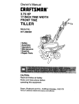
A
2
Look for this symbol to point out important safety precautions.
It means
CAUTION!t! BECOME ALERTI!! YOUR
SAFETY IS INVOLVED.
CAUTION:
Always disconnect
spark
plug wire and place wire where it cannot
contact spark plug in order to prevent
accidental starting when setting up,
transporting,
adjusting
or making
repairs°
I
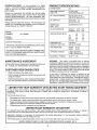
PRODUCT
CONGRATULATIONS
on your purchase of a Sears
Tractor. It has been designed, engineered and manufactured to give you the best possible dependability and
performance.
Should you experience any problem you cannot easily
remedy, please contact your nearest Sears Authorized
Service Center/Department.
We have competent, welltrained technicians and the proper tools to service or repair
this tractor.
Please read and retain this manual. The instructions will
enable you to assemble and maintain your unit properly.
Always observe the "SAFETY RULES".
MODEL
NUMBER
SPECIFICATIONS
HORSEPOWER:
20 0
GASOLINE CAPACITY
AND TYPE:
35 GALLONS
UNLEADED REGULAR
OIL TYPE (API-SF/SG):
SAE 30 (above 32°F)
SAE 5W-30 (below 32°F)
OIL CAPACITY:
W/FILTER:
W/O FILTER:
SPARK PLUG:
(GAP: 025")
CHAMPION
RV17YC
VALVE CLEARANCE:
INTAKE:
EXHAUST:
_003" - 006"
013"016"
GROUND SPEED (MPH):
917.250262
1st
2rid
3rd
Reverse
SERIAL
NUMBER
DATEOFPURCHASE
THEMODELANDSERIALNUMBERSWILLBEFOUND
ON A PLATE UNDER THE SEAT,
YOU SHOULD RECORD BOTH SERIAL NUMBERAND
DATE OF PURCHASE AND KEEP IN A SAFE PLACE
FOR FUTURE REFERENCE
AGREEMENT
A Sears Maintenance
Agreement
uct. Contact your nearest Sears
CUSTOMER
=
the safety
Follow a regularschedule
using your tracton
is available on this prodstore for details
rules,,
in maintaining,
4 QUARTS
SAE 30 API-SF/SG
TIRE PRESSURE:
FRONT:
REAR:
CHARGING
5 AMPS BATTERY
5 AMPS HEADLIGHTS
SYSTEM:
14 PSi
10 PSI
30-35 FT. LBS
In the state of California the above is required by law
(Section 4442 of the California Public Resources Code).
Other states may have similar laws_ Federal laws apply on
federal lands. A spark arrester for the muffler is available
through your nearest Sears Authorized Service Center/
Department (See REPAIR PARTS section of this manual).
caring for and
Follow the instructions
under "Customer
Responsibilities" and "Storage" sections of this owner's manual,,
LIMITED TWO YEAR WARRANTY
HI
18
3,4
56
2.2
WARNING:
This tractor is equipped with an internal
combustion engine and should not be used on or near any
unimproved forest-covered, brush-covered or grass-covered land unless the engine's exhaust system is equipped
with a spark arrester meeting applicable local or state laws
(if any). If a spark arrester is used, it should be maintained
in effective working order by the operator.
RESPONSiBILiTiES
Read and observe
LO
08
14
2.4
09
TRANSAXLE OIL
CAPACITY AND TYPE:
BLADE BOLT TORQUE:
MAINTENANCE
40
35
ON ELECTRIC
START RIDING EQUIPMENT
For two (2) years from the date of purchase, if this riding equipment is maintained, lubricated and tuned up according to the
instructions in the owner's manual, Sears will repair or replace, free of charge, any parts found to be defective in material or
workmanship.
This Warranty does not cover:
•
Expendable items which become worn during normal use, such as blades, spark plugs, air cleaners and belts,
Tire replacement or repair caused by punctures from outside objects, such as nails, thorns, stumps, or glass
Repairs necessary because of operator abuse, negligence, improper storage or accident or the failure to maintain the
equipment according to the instructions contained in the owner's manual
Riding equipment used for commercial or rental purposes,
LIMITED 90 DAY WARRANTY
ON BATTERY
For ninety (90) days from date of purchase, if any battery included with this riding equipment proves defective in material or
workmanship and our testing determines the battery will not hold a charge, Sears will replace the battery at no charge
WARRANTY SERVICE
CENTER/DEPARTMENT
IS AVAILABLE BY RETURNING
iN THE UNITED STATES
THE RIDING EQUIPMENT
TO THE NEAREST
SEARS SERVICE
This Warranty gives you specific legal rights, and you may also have other rights which may vary from state to state
SEARS,
ROEBUCK
AND CO.
D/817 WA, HOFFMAN
3
ESTATES,
ILLINOIS
60179
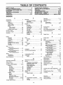
TABLE OF CONTENTS
SAFETY RULES ............................................................
2
PRODUCT SPECIFICATIONS ...................................... 3
CUSTOMER RESPONSIBILITIES ..................... 3, 15-18
WARRANTY ..................................................................
3
TRACTOR ACCESSORIES ..........................................
5
ASSEMBLY .............................................................
7-10
OPERATION ..........................................................
11-14
MAINTENANCE SCHEDULE .....................................
15
SERVICE AND ADJUSTMENTS ........................... 19-25
STORAGE ...................................................................
25
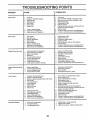
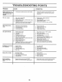
TROUBLESHOOTING ...........................................
28-29
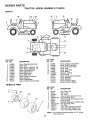
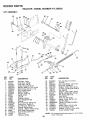
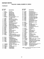
REPAIR PARTS - TRACTOR ................................ 31-47
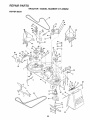
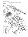
REPAIR PARTS - ENGINE ....................................
48-57
PARTS ORDERING/SERVICE ............... BACK COVER
MNDEX
A
Electrical:
Interlocks and Relays ......................23
Adjustments:
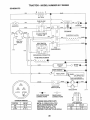
Schematic ..........................................30
Brake .......................................
21
Wiring Diagram .......................................
32
Carburetor ...................................................
25
Engine:
Clutch Pulley ...........................................
21
Air Filter ....................................................
18
Gauge Wheels ............................................
13
Air Screen ...............................
18
Mower
Cooling Fins ........................................18
Front-To-Back ....................................
20
Side-To-Side ...................................
19
Oil Change ...................................
17
Oil Level .................................................
13,17
Throttle Control Cable ................. 23
Oil Type ..............................................17
Air Filter, Engine .................................................
18
Preparation .......................................13
Air Screen, Engine ..............................
18
Repair Parts ....................................
48-57
Assembly ..........................................................
7-10
Starting ...............................................14
Storage ................................................26
Accessories ..................................................5
Operation ..........................................................
t1-14
Operating Mower ................................... 13
Options:
Accessories ...................................
5
Spark Attester ............................... 3,40
P
Parking Brake ..............................................12
Parts Bag ..................................................................
6
Parts, Replacement/Repair
...............48*57
Product Specifications ............................. 3
R
Repair Parts ....................................... 31-47
B
F
Battery:
Filter:
Charging ......................................................
8
Air Filter ............................................ 18
Cleaning .............................................................
16
Installation ........................................ 10
Fuel ................................................................
18
Levels ......................................... 8,17
Oil ..................................................
17
Preparation .....................................................
8
Fuel:
Stading with Weak Battery ........... 23
Storage ...............................................26
Storage .......................................
26
Type ........................................................
12
Terminals ...............................................
16
Fuse ................................................................
23
Belt:
Motion Drive
H
Removal/Replacement ...................
22
Headlights ............................................. 23
Mower Drive
Hood Removal/InstaUation ........................
24
Removal/Replacement .......... 20
Mower Blade Drive
Removal/Replacement ................21
L
Blade:
Leveling Mower Deck ............................ 19
Sharpening ...................................................
16
Lubrication:
Replacement ...............................
16
Chart .......................................................
15
Brake Adjustment ................................................
21
C
M
S
Safety Rules ...................................................
2
Seat ..........................................................................
8
Service and Adjustments .............. 19-25
Carburetor ......................................... 25
Clutch Pulley .................................... 21
Fuse .................................................. 23
Hood Removal/Installation .................
24
Motion Drive Belt
Removal/Replacement
............. 22
Mower Dive Belt
Removal/Replacement
.......... 20
Mower Blade Drive
Removal/Replacement
............ 21
Mower Adjustment
Front-to-Back ...................................
20
Side-to-Side .............................. 20
Mower Removal ................................19
Tire Care ......................................
8,16,23
Slope Guide Sheet .................................. 59
Spark Plug(s) .............................................18
Specifications ........................................... 3
Starting the Engine ................................
13-14
Steering Wheel ......................................7,22
Stopping the Tractor ....................................
12
Storage .........................................................26
Maintenance Schedule ...........................15
Carburetor Adjustment ........................ 25
Mower:
Clutch Pulley .........................................................
21
Adjustment, Front-to-Back ......... 20
Controls, Tractor ...............................................
11
Adjustment, Side-to-Side ............. 19
Customer Responsibilities ....................
15-18
Blade Sharpening .......................... 16
Blade Replacement ...................................
16
Engine:
Air Filter ...................................
18
Cutting Height .............................. 12
T
Installation ......................................... 19
Air Scree ...................................................
18
Operation ....................................... 13
Throttle Control Cable Adjustment ...... 25
Cooling Fins ...........................
18
Removal .......................................................
19
Engine Oil ........................................
17
Tires ................................................................
8,16,23
Fuel Filter ..........................................
18
Mowing Tips .........................................................
14
Trouble Shooting Chart ......................28-29
Spark Plug(s) ............................. 18
Muffler ...................................................................
18
Transaxle .....................................................
16
Tractor:
Spark Arrester ............... ,........... 3,40
Battery .......................................... 17
W
Blade ........................................
16
0
Lubrication Chart ......................................
15
Warranty ..................................................... 3
Oil:
Maintenance Schedule ............ 15
Wiring Diagram ....................................... 32
Tire Care .............................. 8,16,23
Cold Weather Conditions ............
13,17
Wiring Schematic .......................................30
Transaxle ................................. 16
Engine ............................................. 17
Storage
..............................................26
Cutting Height, Mower .....................................
12
4
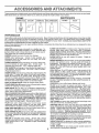
ACCESSORIES
AND ATTACHMENTS
These accessories and attachments were available through most Sears retail outlets and service centers when the tractor was purchased
Most Sears stores can order these items for you when you provide the model number of your tractor
ENGINE
SPARK PLUG
MAINTENANCE
GAS CAN
ENGINE OIL
FUEL STABILIZER
BLADES
BELTS
PERFORMANCE
Sears offers a wide variety of attachments that tit your tractor,
you, This list was current at the time of publication; however,
may be made in these attachments, or some may no longer
accessories
and attachments
that are available for your
Most of these attachments do not require additional hitches
attaching and detaching
Many of these are listed below with brief explanations of how they can help
it may change in future years - more attachments may be added, changes
be available or fit your model Contact your nearest Sears store for the
tractor.
or conversion kits (those that do are indicated) and are designed for easy
SLEEVE CULTIVATOR is 43 inches wide Prepares ground for
seeding, helps weed control Steel frame holds 5 adjustable
sweeps Adjusts vertically, horizontally
(Requires sleeve hitch )
Optional accessory:
steel furrow opener for wider openings for
potatoes, corn, and other deep-seeded crops
SLEEVE HITCH for use with master lift system
Single pin
couples/uncouples
SNOWTHROWER has 42-inch swath Drum-type auger handles
powdery and wet/heavy snow
Mounts easily with simple pin
arrangemenL Discharge chute adjusts from tractor seat, 6-inch
diameter spout discharges snow 10 to 50 feet, Lift controlled at
tractor seat. (Use with chains and wheel weights and/or rear
drawbar weighL)
SPRAYERS use 12-volt DC electric motor that connects to the
tractor battery or other 12-volt source
Includes booms for
automatic spraying and hand held wand for spot spraying Wand
has adjustable spray pattern
For applying herbicides, insecticides, fungicides and liquid fertilizers
AERATOR promotes deep root growth for a healthy lawn Tapered 2 5-inch steel spikes mounted on 10-inch diameter discs
puncture holes in soil at close intervals to let moisture soak in
Steel weight tray for increased penetration
BUMPER protects front end of tractor from damage
CARTS make hauling easy
Variety of sizes available, plus
accessories such as side panel kits, tool caddy, cart cover,
protective mat and dolly_
CORING AERATOR takes small plugs out of soil to allow moisture and nutrients to reach grass roots
36-inch swath
24
hardened steel coring tips 150 Ib capacity weight tray
DISC HARROW has 2 gangs of 4 steel blades that angle from 10
to 20 degrees, 40 inches wide
Can hook 2 units in tandem.
(Requires sleeve hitch )
DOZER BLADE removes snow; grades dirt, sand and gravel. 48
inches wide, 17 inches high, clears 44-inch path when angled
Master lift control lever for operator ease Spring trip for snow
removal on uneven pavement; built-in float for blade to follow
ground contour. Reversible, replaceable scraper bar (Use with
tire chains and wheel weights and/or rear drawbar weight.)
EASY OIL DRAIN VALVE makes oil changes easier, faster
FRONT NOSE ROLLER canters in front of mower deck to reduce
chances of "scalping" on uneven terrain
SPREADER/SEEDERS
make seeding, fertilizing, and weed killing easy. Broadcast spreaders are also useful for granular deicers and sand
SWEEPERS let you collect grass clippings and leaves
TILLER has 8 hp engine to prepare seed beds, cultivate, and
compost garden residue. Chain-drive transmission. Six 11-inch
diameter one piece heat-treated steel tines Tills 30-inch path
(Requires sleeve hitch) Or use 5 hp tow-behind TILLER with 36inch swath to prepare seed beds. cultivate and compost garden
residue. Tiller has its own built-in lift and depth control system and
does NOT require a sleeve hitch Fits any lawn, yard or garden
tractor. Simply hook up to the tractor drawbar and go! Optional
accessories for 5 hp tiller convert unit for dethatching, aerating,
hilling_ _without tools,
GANG HITCH lets you tow 2 or 3 pull-behind attachments at
once, such as sweepers, dethatchers, aerators (not for use with
rollers, carts or other heavy attachments)
MULCH RAKE/DETHATCHER
loosens soil and flips thatch and
matted leaves to lawn surface for easy pickup Twenty spring tine
teeth Usefultopreparebareareasforseeding.
Availableforfront
or rear mounting.
HIGH PERFORMANCE
REEL-ACTION
SPRING TINE DETHATCHER covers 36-inch wide path and
tosses thatch into large hopper Mounts behind tractor
PLOW turns soil 6 inches deep, cuts 10-inch furrow. Crank
adjustment controls depth, 3-position yoke sets width Heavy
steel lands!de for straight furrowing
(Requires sleeve hitch )
RAMP TOPS AND FEET let you load and unload tractor from a
pickup truck Use with 2 x 8 or 2 x 10 lumber
REAR GRADER BLADE is 42 inches wide and operated from
driver's seat, Reversible steel blade can be angled at 30 degrees
for grading Reverses for pushing snow backwards
(Requires
sleeve hitch.)
ROLLER for smoother lawn surface.
36-inch wide. 18-inch
diameterwater-tight drum holds upto 3901bs, of weight Rounded
edges prevent harm to tuff Adjustable scraper automatically
cleans drum,
5
TIRE CHAINS are heavy duty; closely spaced extra-large cross
links give smooth ride, outstanding traction
TRACTOR CAB has heavy duty vinyl fabric over tubular steel
frame, ABS plastic top; clear plastic windshield offers 360 degree
visibility, Hinged metal doors with catch. Keeps operator warm
and dry_ Remove vinyl sides and windshields for use as sun
protector in summer
Optional accessories
include;
tinted/
tempered solid safety glass windshield with hand operated wiper;
12-volt amber caution light for mounting on cab toF
VACS for powerful collection of heavy grass clippings and leaves
Optional wand attachment to pick up debris in hard-to-reach
places VAC/CHIPPER includes a chipper-shredder
WEIGHT BRACKET for drawbar for snow removal applications
Can be mounted on front of tractor for plowing applications
Uses
(1) 55 Ib weight,
WHEEL WEIGHTS for rear wheels provide needed traction for
snow removal or dozing heavy materials
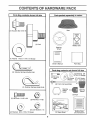
CONTENTS
Parts Bag contents
OF
PACK
shown full size
Parts packed separately
in carton
Seat
(1) Shoulder Bolt 5/16-18
m
÷
(1) Knob
Battery acid
Steering
Wheel
(1) Washer 17/32 x 1-3/16 x 12 Gauge
Owner's Manual
Parts Bag
Parts bag contents
not shown full size
(3) Retainer Springs (double loop)
Washers 3/8
Gauge
(2) Shoulder'
Bolts
_=_(2)
Wheels
(2) Centerlock Nuts
_
Front Link Assemblies
(4) Retainer Springs (single loop)
Steering
Wheel
Insert
Steering
Sleeve
(2) Keys
(2) Hex Bolts 1/4-20 x 3/4
.........
(2) Hex Nuts 1/4-20
;I
-L
(2) Lock Washers
(2) Washers
1/4
9/32 x 5/8 x 16 Gauge
15 ° Slope Sheet
6
Battery Caps
and Instructions
ASSEMBLY
Your new tractor has been assembled at the factorywith the exception of those parts left unassembled for shipping purposes.
To ensure safe and proper operation of your tractor all parts and hardware you assemble must be tightened securely. Use
the correct tools as necessary to insure proper tightness.
TOOLS
REQUIRED
FOR ASSEMBLY
STEERING
WHEEL INSERT
A socket wrench set will make assembly easier. Standard
wrench sizes are listed
HEX BOLT
(2) 7/16" wrenches
Tire pressure gauge
(1) 1/2" wrench
Utility knife
t_
- LOCI(WASHER
(1) 9/16" wrench
(1) 3/4" socket with drive ratchet
When right or left hand is mentioned in this manual, it
means when you are in the operating position (seated
behind the steering wheel)_
TO REMOVE TRACTOR
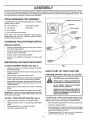
UNPACK
•
STEERING
FROM CARTON
CARTON
STEERING
Remove all accessible loose parts and parts cartons
from carton (See page 6).
_DAPTER _
Cut, from top to bottom, along lines on all four corners
of carton, and lay panels flaL
•
Remove mower and packing materials.
•
Check for any additional loose parts or cartons and
remove.
o
STEERING
WHEEL
"
/:,I,
STEERING
/
z /
STEERIN
SLEEVE /
BEFORE ROLLmNG TRACTOR OFF SKID
A'I-rACH
"
,
/
"
(See Fig. 1)
,
/
FIG. 1
Remove hex bolt, lock washer and large flat washer
from steering shafL
HOW TO SET UP YOUR TRACTOR
Position front wheels of the tractor so they are pointing
straight forward
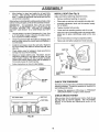
PREPARE
BATTERY
(See Figs. 2A and 2B)
,
Slide steering sleeve over steering shafL
=
Position steering wheel so cross bars are horizontal
(left to right) and slide onto steering wheel adapter.
CAUTION: Wear eye and face shield.
°
Secure steering wheel to steering shaft with hex bolt,
lock washer and large flat washer previously removed
Tighten securely.
Wash hands or clothing immediately if
accidentally in contactwith battery acid.
•
Snap steering wheel insert into center of steering
wheel
Do not smoke, Fumes from charged
battery acid are explosive.
Read the instructions included with the
battery vent caps. Always wear gloves,
clothing and goggles to protect your
hands, skin and eyes,
•
Remove protective plastic from tractor hood and grill.
IMPORTANT:
CHECK FOR AND REMOVE ANY STAPLES
IN SKID THAT MAY PUNCTURE TIRES WHERE TRACTOR
IS TO ROLL OFF SKID.
TO ROLL
=
TRACTOR
OFF
SKID
(See
Your tractor has a battery charging system which is sufficient for normal use However, periodic charging of the
battery with an automotive charger will extend its life.
Fig. 7)
Raise attachment lift lever to its highest position
Release parking brake by depressing clutch/brake
pedal.
Place gearshift lever in neutral (N) position,
Roll tractor backwards off skid,
7
•
See instructions packed with vent caps in parts bag,
o
Lift hood to raised position.
o
Remove battery from tractor to fill with acid and charge.
To remove battery, remove terminal guard and battery
bolts securing battery to tractor.
o
Fill battery with acid. Fill each cell until it reaches the
bottom of the vent wells. Do not overfill
ASSEMBLY
•
Allow battery to stand and settle for at least thirty
minutes.. After standing, check the battery cell acid
level If below the vent wells, add more acid until the
correct level is reached_
While battery
INSTALL
(after adding acid) and later, while
battery is being charged, continue with assembly of tractor.
IMPORTANT:
TO MAXIMIZE
THE LIFE OF YOUR
BATTERY, IT IS NECESSARY
THAT THE BATTERY BE
CHARGED
BEFORE
USE
FAILURE
TO CHARGE
BATTERY
CAN RESULT
IN A SHORTENED
BATTERY
LIFE.
Charge battery at a rate of 6 amperes for 1 hour_ Use
a 12 volt battery charger° Observe all safety precautions required for battery charging.
°
Check the acid level after the battery is charged. If the
acid has fallen below the correct level, add distilled or
iron free water_
o
Install the vent caps to cover the vent wells. Wash the
top of the battery with water to remove any acid, then
wipe dry_
Check battery case for leakage to make sure that no
damage has occurred in handling.
°
.
Dispose of excess battery acid. Neutralize acid for
disposal by adding it to two gallons of water in a five
gallon plastic container, Stir with a wooden or plastic
paddle while adding baking soda until the addition of
more soda causes no more foaming,
°
Follow instructions on how to install battery.
(See Fig. 3)
Adjust seat before tightening adjustment knob.
is standing
°
SEAT
•
Remove cardboard packing on seat pan_
.
Place seat on seat pan and assemble shoulder bolt.
°
Assemble adjustment knob and flat washer loosely.
Do not tighten.
=
Tighten shoulder bolt securely,
=
Lower' seat into operating position and sit on seal
°
Slide seat until a comfortable position is reached which
allows you to press clutch/brake pedal all the way
down.
°
Get off seat without moving its adjusted position°
•
Raise seat and tighten adjustment knob securely.
SEAT
SEAT PAN
\
SHOULDER
BOLT
FLAT WASHER
ADJUSTMENT
KNOB
FIG. 3
BATTERY
BOLTS
CHECK
TIRE PRESSURE
The tires on your tractor'were overinflated at the factory for
shipping purposes. Correct tire pressure is important for
best cutting performance.
°
FIG. 2A
Reduce tire pressure to PSI shown in "PRODUCT
SPECIFICATIONS" on page 3 of this manual.
CHECK
CUT AWAY VIEW
BRAKE
SYSTEM
After you learn how to operate your tractor, check to see
that the brake is properly adjusted_ See "TO ADJUST
BRAKE" in the Service and Adjustments section of this
manual
CELL ACID
LEVEL
FIG. 2B
8
,
BLY
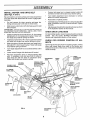
INSTALL
(See
MOWER
Figs.
AND
DRIVE
BELT
4 and 7)
Be sure tractor is on level surface and mower suspension
arms are raised with attachment lift control Engage parking brake,
°
Connect anti-sway bar to chassis bracket under left
footrest and retain with double loop retainer spring.
•
Turn height adjustment knob clockwise
slack from mower suspension.
•
Raise deck to highest position_
to remove
,
Cut and remove tie down securing anti-sway
Swing anti-sway bar to left side of mower deck,
bar
•
•
Slide mower under tractor with discharge guard to right
side of tractor.
Assemble gauge wheels as shown using long shoulder
bolts, 3/8 washers, and 3/8-16 center Iockn uts. Tighten
securely.
=
Ad ust gauge wheels before operating mower as shown
in the Operat on sect on of th s manua.
IMPORTANT;
CHECK BELT FOR PROPER ROUTING iN
ALL MOWER PULLEY GROOVES.
INSTALL BELT INTO
ELECTRIC
CLUTCH PULLEY GROOVE
CHECK
DECK LEVELNESS
o
Install one front link in top hole of the LH. front mower
bracket and L.H. front suspension bracket. Retain with
two single loop retainer springs as shown.
For best cutting results, mower housing should be properly
leveled. See 'q'O LEVEL MOWER HOUSING" in the
Service and Adjustments section of this manual.
o
Install second front linkin R.H. front suspension bracket
and retain with single loop retainer spring as shown
CHECK
BELTS
•
Slide right side of mower deck back and install link in
top hole of R.H. front mower brackeL Retain with single
loop retainer spring as shown.
•
Turn height adjustment knob counterclockwise
stops.
o
Lower mower linkage with attachment lift control
°
Place the suspension arms on inward pointing deck
pins. If necessary, rock and raise front of mower to
align deck pins with the holes in suspension arms.
Retain with double loop retainer springs,
DOUBLELOOP
RETAINER SPRING
PROPER
POSITION
OF
ALL
See the figures that are shown for replacing motion, mower
drive, and mower blade drive belts in the Service and
Adjustments section of this manual Verify that the belts are
routed correctly.
until it
SUSPENSION
ARMS
DOUBLE LOOP
RETAINER SPRING
(Inward pointing
deck pins)
CHASSIS
BRACKET
FOR
FRONT
LINKS
FRONT
SUSPENSION
BRACKET
LECTRIC
CLUTCH
PULLEY ,
L.H. GAUGE
WHEEL BAR
FRONT
SUSPENSION
BRACKET
SINGLE
LOOP RETAINER
SPRINGS
SHOULDER
BOLT
GAUGE
WHEEL
3/8-16
CENTER
LOCKNUT
BRACKET
ANTI-SWAY
BAR
3/8WASHER
IDLER
PULLEY
FIG, 4
GUARD
9
LY
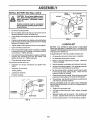
INSTALL
BATTERY
(See Figs. 5 and 6)
LOCK
WASHER
CAUTION: Do not short battery terminals. Before installing battery, remove
metal bracelets, wristwatch bands,
rings, etc.
RE .UT
Positive terminal must be connected
first to prevent sparking from accidental grounding.
o
Lift hood to raised position.
°
Be sure battery drain tube has not come loose and is
securely attached to drain in battery tray.
•
Lower battery into battery tray with terminals to front of
tractor.
•
Position terminal guard overbattery and install battery
bolts through guard mounting holes and into threaded
fasteners on support plate.
o
Tighten battery bolts securely, but do not over tighten.
=
Open terminal access doors.
°
First connect RED battery cable to positive (+) battery
terminal with hex bolt, flat washer, lock washer and hex
nut as shown, Tighten securely.
°
Connect BLACK grounding cable to negative (-) battery
terminal with remaining hex bolt, flat washer, lock
washer and hex nut,, Tighten securely.
Close terminal access doors.
=
DOOR
:
Inspection for secure connections
ware).
°
Inspection for corrosion.
=
Testing battery.
o
Jumping (if required),,
o
Periodic charging.
:_::_i:;_:•"_::;: '':
. F /...
<_>_._ _
THREADED
F] :il
_
;'_
CHECKLIST:
,/
All assembly instructions have been completed.
,/
No remaining loose parts in carton_
,/
Batteryis properly prepared and charged.
1 hour at 6 amps).
J
Seat is adjusted comfortably and tightened securely.
,/
All tires are properly inflated. (For shipping purposes,
the tires were overinflated at the factory).
,/
Be sure mower deck is properly leveled side-to-side/
front-to°rear for best cutting results° (Tires must be
properly inflated for leveling).
,/
Checkmoweranddrivebeltso
Besuretheyarerouted
properly around pulleys and inside all belt keepsr's.
(Minimum
,/
Check wiring. See that all connections are still secure
and wires are properly clamped.
WHILE LEARNING HOW TO USE YOUR TRACTOR,
PA Y EXTRA A TTENTION TO THE FOLLOWING IMPORTANT ITEMS:
GUARD
,/
,/
_BATTERY
_
NEGATIVE
" (BLACK)
CABLE
PLEASE REVIEW THE FOLLOWING
BOLTS
I
POSITIVE
BEFORE YOU OPERATE AND ENJOY YOUR NEW
TRACTOR, WE WISH TO ASSURE THAT YOU RECEIVE
THE BEST PERFORMANCEAND SATISFACTION FROM
THIS QUALITY PRODUCT.
SA ERY
. U
------
,/CHECKLIST
TERMINAL
-:
_-
FIG. 6
(to tighten hard-
F
"1
......
' .....
Use terminal access doors for:
o
FLAT WASHER
TRAY
,/
DRAIN TUBE
,/
FIG. 5
10
Engine oil is at proper level
Fuel tank is filled with fresh, clean, regular unleaded
gasoline.
Become familiar with all controls - their location and
function. Operate them before you start the engine.
Be sure brake system is in safe operating condition.
OPEF AT ON
KNOWYOURTRACTOR
READ THIS OWNER'S
MANUAL
AND SAFETY
RULES
BEFORE
OPERATING
YOUR
TRACTOR
Compare the illustrations with your tractor to familiarize yourself with the locations of various controls and adjustments,
this manual for future reference_
AMMETER
THROTTLE
CONTROL
ATTACHMENT
CLUTCH SWITCH
CHOKE
CONTROL
Save
LIFT LEVER
---
LIGHT
SWITCH
LIFT LEVER
CLUTCH/BRAKEPEDAL
HEIGHT ADJUSTMENT
KNOB
RANGE SHIFTLEVER
PARKING BRAKE LEVER
GEARSHIFT
LEVER
FIG. 7
Our tractors conform to the safety standards of the American National Standards Institute,
ATTACHMENT CLUTCH SWITCH - Used to engage mower
blades or other attachments mounted to your tractor,
RANGE SHIFT LEVER - Allows high (H) or low (L) speed
for all forward and reverse gears.
LIFT LEVER- Used to raise and lower mower deck or other
attachments mounted to your tractor.
LIFT LEVER PLUNGER - Used to release attachment lift
lever when changing its position.
IGNITION SWITCH - Used to start and stop the engine
CLUTCH/BRAKE
PEDAL - Used for deciutching
braking the tractor and starting the engine.
PARKING BRAKE LEVER - Locks clutch/brake pedal into
the brake position,
GEARSHIFT
tractor,
THROTTLE
AMMETER - Indicates battery charging (+) or discharging
(-)
LIGHT SWITCH - Turns the headlights on and off,
and
LEVER - Selects the speed and direction of
CHOKE CONTROL - Used when starting a cold engine,
HEIGHTADJUSTMENT
height.
CONTROL - Used to control engine speed
11
KNOB- Used to adjustthe mower
OPERATION
The operation of any tractor can result in foreign objects thrown into the eyes, which can result
in severe eye damage. Always wear safety glasses or eye shields while operating your tractor
or performing any adjustments or repairs. We recommend a wide vision safety mask over the
spectacles or standard safety glasses.
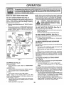
HOW TO USE YOUR TRACTOR
TO SET
PARKING
BRAKE
(See
Fig. 8)
Your tractor is equipped with an operator presence sensing
switch_ When engine is running, any attempt by the
operator to leave the seat without first setting the parking
brake will shut off the engine,
o
IGNITION
KEY
PUSH IN TO
"DISENGAGE"
ATTACHMENT
CLUTCH SWITCH
PULL OUT TO
"ENGAGE"
pletely, as described above, before leaving the operator's position; to empty
grass catcher, etc.
TO USE THROTTLE
CONTROL
THROTTLE
CONTROL
LEVER
"BRAKE"
POSITION
RANGE
SHIFT
LEVER
HEIGHT
ADJUSTMENT
KNOB
TO USE
CHOKE
CONTROL
(See
Fig. 8)
GEARSHIFT
LEVER
AND BACKWARD
The direction and speed of movement is controlled by the
gearshift lever_
•
Start tractor with clutch/brake pedal depressed and
gearshift lever in neutral (N) position_
°
Move gearshift and range shift levers to desired position.
o Slowly release clutch/brake pedal to start movement.
IMPORTANT: BRING TRACTOR TO A COMPLETE STOP
BEFORE SHIFTING OR CHANGING GEARS. FAILURE
TO DO SO WILL SHORTEN THE USEFUL LIFE OF YOUR
TRANSAXLE
TO ADJUST
MOWER
CUTTING
HEIGHT
(See Fig. 8)
FIG. 8
STOPPING
(See Fig. 8)
MOWER BLADES .
Move attachment clutch switch to "DISENGAGED"
position
GROUND DRIVE o
Depress clutch/brake pedal into full "BRAKE" position_
.
Move gearshift lever to neutral (N) position.
ENGINE Move throttle control to slow (,_)
Fig. 8)
Always operate engine at full throttle,
•
Operating engine at less than full throttle reduces the
battery charging rate°
o Full throttle offers the best mower performance,
TO MOVE FORWARD
(See Fig. 8)
"DISENGAGED"
POSITION
(See
Use choke control whenever you are starting a cold engine
Do not use to start a warm engine.
= To engage choke control, pull knob out Slowly push
knob in to disengage
CHOKE
CONTROL
CLUTCH/
BRAKE
PEDAL
"DRIVE"
POSITION
!
NOTE: Undercertainconditions
whentractorisstanding
idle with the engine running, hot engine exhaust gases may
cause "browning" of grass. To eliminate this possibility,
always stop engine when stopping tractor on grass areas.
Depress clutch/brake pedal into full "BRAKE" position
and hold.
Place parking brake lever in "ENGAGED" position and
release pressure from clutch/brake pedal Pedal should
remain in "BRAKE" position. Make sure parking brake
will hold tractor secure_
!
position_
NOTE: Failure to move throttle control to slow (,_=_)
position and allowing engine to idle before stopping may
cause engine to "backfire"
o Turn ignition key to "OFF" position and remove key.
Always remove key when leaving tractor to prevent
unauthorized use.
°
Never use choke to stop engine_
12
The cutting height is controlled by turning the height adjustment knob in desired direction.
° Turn knob clockwise ((-_) to raise cutting height.
°
Turn knob counterclockwise (_-_) to lower cutting
heighL
The cutting height range is approximately 1-1/4" to 4-1/4"o
The heights are measured from the ground to the blade tip
with the engine not running. These heights are approximate and may vary depending upon soil conditions, height
of grass and types of grass being mowed.
° The average lawn should be cut to approximately 2-1/2
inches during the cool season and to over 3 inches
during hot months_ For healthier and better looking
lawns, mow often and after moderate growth.
°
For best cutting performance, grass over 6 inches in
height should be mowed twice_ Make the first cut
relatively high; the second to desired height,
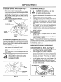
OPERATUON
TO ADJUST
•
•
GAUGE
WHEELS
(See
Fig.
TO OPERATE
9)
Adjust mower to desired cutting height.
Lower mower with lift control Remove rear retainer
spring and clevis pin which secure each gauge wheel
o
l
Lower gauge wheels to ground. Raise gauge wheels
slightly to align holes in bracket and gauge wheel bar
and insert clevis pins. Gauge wheels should be slightly
oft the ground,
,
_
o
°
o
Replace retainer springs into clevis pins
RETAINER
(_
SPRING
'_
•
TO OPERATE
MOWER
When pushing or towing your tractor, be sure gearshift
lever is in neutral (N) position
Do not push or tow tractor at more than five (5) MPH.
NOTE: To protect hood from damage when transporting
your tractoron atruck or atrailer, be sure hood is closed and
secured to tractor. Use an appropriate means of tying hood
to tractor (rope, cord, etc).
(See Figs. 7 and 8)
Your tractor is equipped with an operater presence sensing
switch. Any attempt by the operator to leave the seat with
the engine running and the attachment clutch engaged will
shut off the engine.
•
•
Select desired height of cut
Lower mower with attachment lift control.
o
Start mower blades by engaging attachment clutch
control.
BEFORE STARTING
CAUTION:
Do not operate the mower
without either the entire grass catcher,
THE ENGINE
CHECK
ENGINE
OiL LEVEL (See Fig. 11)
The engine in your tractor has been shipped, from the
factory, already filled with summer weight oil
Check engine oil with tractor on level ground.
Remove oil fill cap/dipstick and wipe clean, reinsert the
dipstick and push it all the way down into the tube, wait
for a few seconds, remove and read oil level. If
necessary, add oil until "FULL" mark on dipstick is
reached_ Do not overfill
TO STOP MOWER BLADES - disengage attachment
clutch control
on mowers so equipped,
charge guard in place.
lift to highest position with attach-
=
FIG. 9
_
I
Choose the slowest speed before starting up or down
hills.
Avoid stopping or changing speed on hills.
If slowing is necessary, move throttle control lever to
slower position.
If stopping is absolutely necessary, push clutch/brake
pedal quickly to brake position and engage parking
brake
Move gearshift lever to 1st gear and range shift lever to
low (L) position. Be sure you have allowed room for
tractor to roll slightly as you restart movement.
To restart movement, slowly release parking brake and
clutch/brake pedal,
Make all turns slowly_
Raise attachment
ment lift control
BRACKET
_
_,_
hills with slopes greater than 15 ° and
CAUTION:
not drive
up or down
do
not drive Do
across
any slope.
TO TRANSPORT
WHEEL
I
ON HILLS
I
or the dis-
•
For cold weather operation you should change oil for
easier starting (See "OIL VISCOSITY CHART" in the
Customer Responsibilities section of this manual)
To change engine oil, see the Customer Responsibilities section in this manual
OIL CAP/DIPSTICK
RUNNER
DISCHARGE
GUARD
FIG, 11
FIG. 10
13
OPERATION
ADD GASOLINE
MOWING T PS
o
o
Fill fuel tank. Use fresh, clean, regular unleaded
gasoline, (Use of leaded gasoline will increase carbon
and lead oxide deposits and reduce valve life),
IMPORTANT: WHEN OPERATING IN TEMPERATURES
Use the runner on the right hand side of mower as a
guide. The blade cuts approximately an inch outside
the runner (See Fig. 10)..
WARNING:
Experience indicates that alcohol blended
fuels (called gasohol or using ethanol or methanol) can
attract moisture which leads to separation and formation of
acids during storage. Acidic gas can damage the fuel
system of an engine while in storage. To avoid engine
problems, the fuel system should be emptied before storage of 30 days or longer. Drain the gas tank, start the
engine and let it run until the fuel lines and carburetor are
empty. Use fresh fuel next season, See Storage Instructions for additional information
Never use engine or
carburetor cleaner products in the fuel tank or permanent
damage may occun
Q
@
START
ENGINE
(See
Fig.
!
8)
When starting engine for the first time or' if engine has run
out of fuel, it will take extra cranking time to move fuel from
the tank to the engine
o
Depress clutch/brake pedal and set parking brake.
=
Place gearshift lever in neutral (N) position.
Move attachment clutch to "DISENGAGED" position.
Move throttle control to midway between fast (,_) and
slow (,_,) positions°
o
Insert key into ignition and turn key clockwise to"START"
position and release key as soon as engine starts. Do
not run starter continuously for more than fifteen
seconds per minute. If engine does not start after
several attempts, move throttle control to fast (=_)
position, wait a few minutes and try again,
°
When engine starts, slowly push choke control in_
°
Move throttle control to fast (,€_) position.
If grass is extremely tall, it should be mowed twice to
reduce load and possible fire hazard frorn dried clippings_ Make first cut relatively high; the second to the
desired height.
Do not mow grass when it is weL Wet grass will plug
mower and leave undesirable clumps.. Allow grass to
dry before mowing.
Always operate engine at full throttle when mowing to
assure better mowing performance and proper discharge of material. Regulate ground speed by selecting a low enough gear to give the mower cutting
performance as well as the quality of cut desired.
When operating attachments, select a ground speed
that will suit the terrain and give best performance of
the attachment being used.
Pull choke control out to choke (l\l) position for cold
engine start. For warm engine start do not use choke
control
o
The left hand side of mower should be used for trimruing.
Drive so that clippings are discharged onto the area
that has been cut. Have the cut area to the right of the
machine. This will result in a more even distribution of
clippings and more uniform cutting.
When mowing large areas, start by turning to the right
so that clippings will discharge away from shrubs,
fences, driveways, etc. After one or two rounds, mow
in the opposite direction making left hand turns until
finished (See Fig 12).
!
TO
is
Mower should be properly leveled for best rnow!rlg
performance. See 'TO LEVEL MOWER HOUSING in
the Service and Adjustments section of this rnanual.
STARTING
CAUTION: Fill to bottom of gas tank
filler neck. Do not overfill. Wipe off any
spilled oil or fuel. Do not store, spill or
use gasoline near an open flame.
Tire chains cannot be used when the mowerhousing
attached to tractor.
Allow engine to warm up for a few minutes before
engaging drive or' attachments.
FIG. 12
NOTE: If at a high altitude (above 3000 feet) or in cold
temperatures (below 32°F), the carburetor fuel mixture
may need to be adjusted forbest engine performance. See
'q'O ADJUST CARBURETOR" in the Service and Adjustments section of this manual.
14
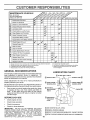
CUSTOMER
RESPONSIBiLiTiES
REOUL RBERV,CE
AS YOU COMPLETE
Check
Brake
Check
Tire Pressure
Check for Loose Fasteners
a
Sharpen/ReplaceMower Blades
C
Lubrication Chart
Check Battery Level/Recharge
Clean Battery and Terminals
Check Transaxle Cooling
0
a
DATES
Operation
T
T
YSERVICE
Adjust Blade Belt(s) Tension
Adjust Motion Drive Belt(s) Tension
Check Engine Oil Level
Change Engine Oil
Clean Air Filter
E
N Clean Air Screen
G
I
Inspect MuffledSpark Arrester
Replace Oil Filter (if equipped)
N
E
Clean Engine Cooling Fins
v'
Replace Spark Plug
Replace Air Filter Paper Cartridge
J
Replace Fuel Filter
12 3 4 -
Change more often when operaling under a heavy load or tn high ambient lemperatures
Service more often when operating in dirty or dusty conditions
If equipped wilh oil lilter, change oiI every 50 hours
Replace blades more olten when mowlng in sandy soil
GENERAL
RECOiVliVIEN DATUONS
LUBRBCATUON CHART
The warranty on this tractor does not cover items that have
been subjected to operator abuse or negligence.
To
receive full value from the warranty, operator must maintain
tractor as instructed in this manual
®TIE
REARING
Once a year you should replace the spark plug, clean
or replace air filter, and check blades and belts for
wear. A new spark plug and clean air filter assure
proper air-fuel mixture and help your engine run better
and last Ionger.
Check tire pressure.
Check for loose fasteners.
IMPORTANT:
DO NOT OIL OR GREASE THE PIVOT
POINTS
WHICH HAVE SPECIAL
NYLON BEARINGS.
VISCOUS LUBRICANTS
WILL ATTRACT DUST AND DIRT
THAT
WILL
SHORTEN
THE LIFE
OF THE SELFLUBRICATING
BEARINGS.
IF YOU FEEL THEY MUST
BE LUBRICATED,
USE ONLY A DRY, POWDERED
GRAPHITE
TYPE LUBRICANT
SPARINGLY
ENGINE (_
SECTORGEAR
TEETH
(_) CHECK/ADD--.
TRANSAXLE
FLUID
Check engine oil level
°
o
ZERK (_
_ FRONT WHEEL (_)
BEARING ZERK
ZERK
(_
EACH USE
Check brake operation
SPINDLE
®
All adjustments in the Service and Adjustments section of
this manual should be checked at least once each season.
•
ROD BALL JOINTS
®
Some adjustments will need to be made periodically to
properly maintain your tractor.
BEFORE
5 - If equipped wilh adjustabfe system
6 - Not required if equtpped with maintenance-free
battery
7 • Tighten Iront axle pivot bog to 35 ft -_bs maximum
Do not overlighlen
(_SAE
30 MOTOR OIL API - SF/SG
_) GENERAL PURPOSE
GREASE
(_ REFER TO CUSTOMER
(_)SPRAY
15
RESPONSIBILITIES
SILICONE LUBRICANT
"ENGINE"
SECTION
(MOVE BOOTS TO LUBRICATE)
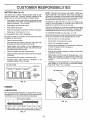
CUSTOM
LITnE$
TRACTOR
o
The blade can be sharpened with a file or on a grinding
wheel Do not attempt to sharpen while on the mower,
Always observe safety rules when performing any maintenance.
=
To check blade balance, you will need a 5/8" diameter
steel bolt, pin, or a cone balancer.. (When using a cone
balancer, follow the instructions supplied with balancer).
o
Slide blade on to an unthreaded portion of the steel bolt
or pin and hold the bolt or' pin parallel with the ground.
If blade is balanced, it should remain in a horizontal
position If either end of the blade moves downward,
sharpen the heavy end until the blade is balanced_
BRAKE
OPERATION
If tractor requires more than six (6) feet stopping distance
at high speed in highest gear, then brake must be adjusted_
(See "TO ADJUST BRAKE" in the Service and Adjust _
ments section of this manual)
TIRES
=
Maintain proper' air pressure in all tires (See "PRODUCT SPECIFICATIONS" on page 3 of this manual),
o
Keep tires free of gasoline, oil, or insect control chemicals which can harm rubber_
=
Avoid stumps, stones, deep ruts, sharp objects and
other hazards that may cause tire damage_
BLADE
CENTER
HOLE
5/8" BOLT
CARE
For' best results mower blades must be kept sharp,
place bent or damaged blades,
BLADE
NOTE: Do not use a nail for balancing blade. The lobes of
the center hole may appear to be centered, but are not..
REMOVAL
BLADE
oR
Re-
(See Fig. 13)
o
Raise mower to highest position to allow access to
blades.
o
Remove hex bolt, Iockwasher and flat washer securing
blade.
V-BELTS
Install new or resharpened blade with trailing edge up
towards deck as shown.
Check V-belts for deterioration and wear after 100 hours
and replace if necessary. The belts are not adjustable..
Replace belts if they begin to slip from wear_
°
FIG. 14
Reassemble hex bolt, lock washer and flat washer' in
exact order as shown
TRANSAXLE
o Tighten bolt securely (30-35 FL Lbs. torque)..
IMPORTANT: BLADE BOLT IS GRADE 8 HEAT TREATED
COOLING
Keep transaxle free from build-up of dirt and chaff which
can restrict cooling_
NOTE: We do not recommend sharpening blade- but if you
do, be sure the blade is balanced°
CHECK TRANSAXLE
OIL LEVEL
(See Fig. 15)
MANDREL
BLADE
°
Block up rear'axle securely..
•
Remove left rear wheel by removing hub bolts.
°
Remove filler plug from transaxle. Oil level must be
even with plug threads. If necessary, fill with SAE 30
motor oil, API-SF or SG Replace filler plug..
Reassemble wheel to hub.
TRAILING
EDGE UP
°
FLAT WASHER',
=
For approximate capacity see "PRODUCT SPECIFICATIONS on page 3 of this manual
HEX BOLT (GRADE 8)*_
TRANSAXLE
*A GRADE 8 HEAT TREATED BOLT CAN BE
IDENTIFIED BY SIX LINES ON THE BOLT HEAD,
/
O
O
FIG, 13
TO SHARPEN
BLADE
(See
J
Fig. 14)
Care should be taken to keep the blade balanced. An
unbalanced blade wilt cause excessive vibration and eventual damage to mower and engine.
FIG. 15
16
FILLER PLUG
CUSTOMER
BATTERY
RESPONSUB LUTUES
(See Fig. 16)
NOTE: Although multi-viscosity oils (5W30, 10W30 etc.)
improve starting in cold weather, these multi-viscosity oils
will result in increased oil consumption when used above
32°F. Check your engine oil level more frequently to avoid
possible engine damage from running low on oil
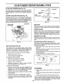
Your tractor has a battery charging system which is sufficient for normal use However, periodic charging of the
battery with an automotive charger will extend its life.
•
Acid solution level in each battery cell should be even
with bottoms of vent wells Add only distilled or iron free
water if necessary. Do not overfill
.
Keep battery and terminals clean.
o
Keep battery bolts tight.
•
Keep vent caps tight and small vent holes in caps open,
•
Recharge at 6 amperes for 1 hour_
TO CLEAN BATTERY AND TERMINALS
Change the oil after the first two hours of operation and
every 50 hours thereafter or at least once a year if the
tractor is not used for 50 hours in one year,
Check the crankcase oil level before starting the engine
and after each eight (8) hours of operation. Tighten oil fill
cap/dipstick securely each time you check the oil level
TO CHANGE ENGINE OIL (See Figs. 17 & 18)
-
Determine temperature range expected before oil change,,
All oil must meet API service classification SF or SG,
Corrosion and dirt on the battery and terminals can cause
the battery to "leak" power,
=
Remove terminal guard.
=
Disconnect BLACK battery cable first then RED battery cable and remove battery from tractor.
•
Wash battery with solution of four tablespoons of
baking soda to one gallon of water. Be careful not to get
the soda solution into the cells,
•
Oil will drain more freely when warm,
Catch oi! in a suitable container,
°
Remove oil fill cap/dipstick. Be careful not to allow dirt
to enter the engine when changing oil
•
Remove drain plug
After oil has drained completely, replace oil drain plug
and tighten securely_
Refill engine with oil through oil fill dipstick tube. Pour
slowly. Do notoverfill
For approximate capacity see
"PRODUCT SPECIFICATIONS"
on page 3 of this
=
Rinse the battery with plain water and dry.
°
•
Clean terminals and battery cable ends with wire brush
until bright,
•
Coat terminals with grease or petroleum jelly.
•
Reinstal! battery (See "INSTALL BATTERY"
Assembly section of this manual).
in the
manual,
°
CUT AWAY VIEW
[
L.-----J
L---.--,J
L,--.....J
Be sure tractor is on level surface.
Use gauge on oil fill cap/dipstick for checking level. Be
sure dipstick is in all the way for accurate reading,
Keep oil at "FULL" line on dipstick.
fjVE.TOAP
VENT
OIL DRAIN PLUG
WELL
BATTERY
CELL ACID
LEVEL
OIL FILL
CAP/DIPSTICK
FIG, 16
ENGINE
LUBRICATION
Only use high quality detergent oil rated with API service
classification S F or SG. Select the oirs SAE viscosity grade
according to your expected operating temperature,
SAE VISCOSITY GRADES
FIG. 18
÷20"
-3'0o
0_
-2_"
TEMPERATURE
30°
-loo
32 _ 40"
o°
RANGE ANTICIPATED
60"
loo
soo
=0o
BEFORE NEXT OIL CHANGE
FIG. 17
17
CUSTOMER
CLEAN
AIR
SCREEN
(See
RESPONSIBILITIES
Fig. 19)
Air screen must be kept free of dirt and chaff to prevent
engine damage from overheating_ Clean with a wire brush
or compressed air to remove dirt and stubborn dried gum
fibers..
ENGINE
COOLING
FINS
(See
Fig. 19)
Remove any dust, dirt or oil from engine cooling fins to
prevent engine damage from overheating_ Engine blower
housing must be removed. Remove side panels and hood
(See "TO REMOVE HOOD AND GRILL.ASSEMBLY" in the
Service and Adjustments section of this rnanual).
FIG. 20
AIR SCREEN
COOLING FINS
(BOTH SIDES)
MUFFLER
Inspect and replace corroded muffler and spark arrester (if
equipped) as it could create a fire hazard and/or damage.
\
SPARK
PLUGS
Replace spark plugs at the beginning of each mowing
season or after every 100 hours of operation, whichever
comes first. Spark plug type and gap setting are shown in
"PRODUCT SPECIFICATIONS" on page 3 of this manual.
\
ENGINE
OIL FILTER
Replace the engine oil filter every season or every other oil
change if the tractor is used more than 100 hours in one
year,
IN-LINE
FIG. 19
AIR FILTER
FILTER
(See
Fig. 21)
The fuel filter should be replaced once each season. If fuel
filter becomes clogged, obstructing fuel flow to carburetor,
replacement is required,
o With engine cool, remove filter and plug fuel line
sections.
°
Place new fuel filter in position in fuel line with arrow
pointing towards carburetor.
°
Be sure there are no fuel line leaks and clamps are
properly positioned.
o
Immediately wipe up any spilled gasoline.
(See Fig. 20)
Your engine wilt not run properly using a dirty air filter.
Ctean the foam pre-cleaner element after every 25 hours of
operation or every season_ Service paper cartridge every
100 hours or every season, whichever occurs firsL
Service air cleaner more often under dusty conditions,
o
FUEL
Remove wing nut and cover,,
o Remove seal and cartridge plate_
TO SERVICE PRE-CLEANER
=
Slide foam pre-cleaner off cartridge,
°
Wash it in liquid detergent and water.
o
Squeeze it dry in a clean cloth,
o
Saturate it in engine oil, Wrap it in clean, absorbent
cloth and squeeze to remove excess oil
TO SERVICE CARTRIDGE
=
•
FIG. 21
Gently tap the flat side of the paper cartridge to dislodge dirt,. Do not wash the paper cartridge or use
pressurized air, as this will damage the cartridge.
Replace a dirty, bent, or damaged cartridge.
CLEANING
Reinstall the pre-cleaner (cleaned and oiled) over the
paper cartridge.
Reassemble air cleaner, cartridge plate, and seal
°
Install the air cleaner cover and wing nut, Tighten wing
nut 1/2 turnto 1 full turn after nut contacts cover. Do not
overtighten.
18
°
Clean engine, battery, seat, finish, etc. of all foreign
matter.
°
Keep finished surfaces and wheels free of all gasoline,
oil, etc.
o
Protect painted surfaces with automotive type wax,
We do not recommend using a garden hose to clean your
tractor unless the electrical system, muffler, air filter and
carburetor are covered to keep water out. Water in engine
can result in a shortened engine life_
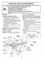
;ERVUCE AND ADJUSTMEHT$
CAUTION:
o
o
•
°
°
o
BEFORE PERFORMING ANY SERVICE OR ADJUSTMENTS:
Depress clutch/brake pedal fully and set parldng brake.
Place gearshift lever in neutral (N) position.
Place attachment clutch in "DISENGAGED"
position.
Turn ignition key "OFF" and remove key.
Make sure the blades and all moving parts have completely stopped.
Disconnect spark plug wire from spark plug and place wire where it cannot come in contact
with plug.
TRACTOR
TO REMOVE
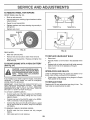
TO LEVEL
MOWER
SIDE-TO-SIDE ADJUSTMENT (See Figs. 22 and 23)
Raise mower to its highest position
Measure height from bottom of deck curl to ground
level at front corners of mower Distance "A" on both
sides of mower should be the same
•
NOTE: Each full turn of adjustment nut will change mower
height about 3/16"
Recheck measurements after adjusting
MOWER
BOTTOM
OF CURL
BOTTOM
OF CURL
_
FRONT
SUSPENSION
BRACKET
ADJUSTMENT
NUTS
If adjustment is necessary, make adjustment on one
side of mower only
To raise one side of mower, tighten lift link adjustment
nut on that side
To lower one side of mower, loosen lift link adjustment
nut on that side
Follow procedure described in "INSTALL MOWER AND
DRIVE BELT" in the Assembly section of this manual
SUSPENSION
ARMS
HOUSING
Adjust the mower while tractor is parked on level ground or
driveway
Make sure tires are properly inflated (See
"PROD UCT SPECIFICATIO NS" on page 3 of this manual)
If tires are over or underinflated, you will not properly adjust
your mower
(See Fig. 22)
Place attachment clutch in "DISENGAGED" position
Turn height adjustment knob to lowest setting
Lower mower to its lowest position
Remove retainer spring holding anti-swaybar to chassis bracket and disengage anti-swaybar from bracket
Remove retainer springs from suspension arms at
deck and disengage arms from deck
Raise attachment lift to its highest position
Remove two retainer springs from each front link and
remove links
Slide mower forward and remove belt from electric
clutch pulley
Slide mower out from under right side of tractor
IMPORTANT: IFAN ATTACHMENT OTHER THAN THE
MOWER DECK IS TO BE MOUNTED ON THE TRACTOR,
REMOVE THE FRONT LINKS
TO INSTALL
MOWER
LIFT
LINKS
\
FIG, 23
FRONT MOWER
BRACKET
ELECTRIC
CLUTCH
PULLEY
CHASSIS
SUSPENSION
BRACKET
RETAINER
:"
RETAINER
SPRING
ANTI-SWAY
BAR
RETAINER
SPRINGS
FIG. 22
19
FRONT MOWER
BRACKET
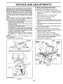
SERVICE
ADJUSTMENTS
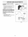
TO REPLACE
FRONT-TO-BACK ADJUSTMENT (See Figs. 24 and 25) IMPORTANT: DECK MUST BE LEVELSIDE-TO-SIDE_ IF
THE FOLLOWING FRONT-TO-SACK ADJUSTMENT IS
NECESSARY, BE SURE TO ADJUST BOTH FRONT LINKS
EQUALLY SO MOWER WILL STAY LEVEL SIDE-TO.SIDE
To obtain the best cutting results, the mower housing
should be adjusted so the front is approximately 1/8" to 1/2"
lower than the rear when the mower is in its highest
position_
Check adjustment on right side of tractor. Measure distance "F" directly in front of and behind the mandrel at
bottom edge of mower housing as shown.
o Before making any necessary adjustments, check that
both front links are equal in length_
o
If links are not equal in length, adjust one link to same
length as other' link.
To lower front of mower housing, loosen nut"G" on both
front links an equal number of turns
o When distance "F" is 1/8" to 1/2" lower at front than
rear tighten nut"H" against trunnion on both front links,
o To raise front of mower housing, loosen nut H from
trunnion on both front links_ Tighten nut "G" on both
front links an equal number of turns.
= When distance "F" is 1/8" to 1/2" lower at front than
rear, tighten nut "H" against trunnion on both front
links.
NOTE: Each full turn of nut "G" will change dim. "F" by
approximately 3/8".
Recheck side-to-side adjustment.
,_;. Oo
Io
_,o1
MOWER
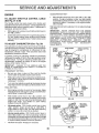
DRIVE
BELT
MOWER DRIVE BELT REMOVAL (See Fig. 26) o
Parktractoron a level surface_ Engage parking brake.
•
Remove four screws from L.H. mandrel cover and
remove cover.
=
Roll belt over the top of L.H. mandrel pulley.
°
Remove belt from electric clutch pulley.
,,
Remove belt from idler pulleys.
°
Remove any dirt or grass clippings which rnay have
accumulated around mandrels and entire upper' deck
surface.
o
Check primary idler arm and two idlers to see that they
rotate freely..
o
Be sure spring is securely hooked to primary idler arm
and bolt in mower housing,.
MOWER DRIVE BELT INSTALLATION (See Fig. 26) ,, Install belt in both idlers_ Make sure belt is in both belt
keepers at the idlers as shown,
°
Install new belt onto electric clutch pulley.
°
Roll belt into upper groove of LH. mandrel pulley.
°
Carefully check belt routing making sure belt is in the
grooves correctly and inside belt keepers_
Reassemble L.H_ mandrel cover.
°
SPRING
L,H,
MANDREL
MANDREL
COVER
SCREWS
IDLER
PULLEYS
ELECTRIC
CLUTCH
PULLEY
PRIMARY
IDLER ARN
FIG. 24
BOTH FRONT LINKS SHOULD
BE EQUAL. IN LENGTH
MOWER
HOUSING
MANDREL
MOWER
DRIVE
BELT
BELT
KEEPERS
LIT "G"
FIG. 26
NUT "H
FRONT LINKS
FIG. 25
20
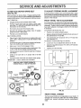
SERVICE ANO ADJUSTMENTS
TO
REPLACE
MOWER
BLADE
DRIVE
BELT
CLUTCH PLATE
(See Fig. 27)
Park the tractor on level surface, Engage parking brake,,
°
Remove mowerdrive belt (See'q-O REPLACE MOWER
DRIVE BELT" in this section of this manual).
°
Remove mower (See "TO REMOVE MOWER" in this
section of this manual),
.
Remove four screws from R.H. mandrel cover and
remove cover. Unhook spring from bolt on mower
housing,
o Carefully roll belt off RH mandrel pulley.
o Remove belt from center mandrel pulley, idler pulley,
and L.H. mandrel pulley
°
Remove any dirt or grass which may have accumulated around mandrels and entire upper deck surface.
•
Check secondary idler arm and idler to see that they
rotate freely_
o
Be sure spring is hooked in secondary idler arm and
sway-bar bracket,
o
Install new belt in lower groove of L.H. mandrel pulley,
idler pulley, and center mandrel pulley as shown.
°
Rol! belt over R.H. mandrel pulley. Make sure belt is in
all grooves properly_
•
Reconnect spring to bolt in mower housing and reinstall RH_ mandrel cover_
Reinstall mower to tractor (See "TO INSTALL MOWER"
in the Assembly section of this manual),
o
Reassemble mower drive belt (See "TO REPLACE
MOWER DRIVE BELT" in this section of this manual
L.H.
MOWER BLADE
DRIVE BELT
NYLON LOCKNIJT (3)
FIG. 28
TO ADJUST
CENTER
°
Loosen jam nut at clevis which will allow brake rod to be
rotated_
o
With pliers, from underside of frame, unscrew brake
rod from clevis four (4) to six (6) full turns,
Start tractor with gear shift lever in neutral (N) position.
Slowly depress clutch/brake pedal to the point where
the motion drive belt stops moving Hold clutch/brake
pedal in this position and engage parking brake. If belt
begins to move after engaging parking brake, reset
parking brake by depressing clutch/brake pedal slightly
to next notch on parking brake_
Stop engine. Screw brake rod back into clevis until
clevis pin is against rear edge of slot in brake arm_ Do
not over tighten (see "IMPORTANT" above)_
Tighten jam nut against clevis
Replace access hole cover,
Road test tractor for proper stopping distance and
declutching as stated above. Readjust if necessary. If
proper adjustment cannot be attained, further maintenance is necessary Contact your nearest authorized
service centeddepartmenL
SPRING
/,'
/
'_/
°
FIG. 27
TO ADJUST
ATTACHMENT
(See Fig. 29)
If tractor requires more than six (6) feet stopping distance
at high speed in highest gear, then brake must be adjusted.
IMPORTANT: DO NOT OVER TIGHTEN BRAKE WHEN
DEPRESSING CLUTCH BRAKE PEDAL, THE MOTION
DRIVE BELT MUST STOP MOVING(DECLUTCH
FROM
ENGINE
PULLEY)
BEFORE
BRAKE ENGAGES,
IMPROPER ADJUSTMENT WILL CAUSE HARD SHIFTING
AND EXCESSIVE WEAR TO BRAKE LINING
°
Park and turn off the tractor on a level surface Place
gear shift lever in neutral (N) position, Disengage
parking brake and be sure tractor does not roll in either
direction_
°
Lower mower deck (if installed on tractor)_
Snap out access hole cover on left side of tractor above
footrest_
SECONDARY
IDLER ARM
IDLER
PL
BRAKE
Your tractor is equipped with an adjustable brake system
which is mounted on the left side of the transaxle.
MANDREL
COVER
SWAY-BAR
BRACKET
BRAKE PLATE
CLUTCH
(See Fig. 28)
The electric clutch should provide years of service, The
clutch has a built-in brake that stops the pulley within 5
seconds_ Eventually, the internal brake will wear which
may cause the mower blades to not engage, or, to not stop
as required. Adjustments should be made by your nearest
authorized service center/department,
Make sure attachment clutch and ignition switches are
in "OFF" position
Adjust the three nylon Iocknuts until space between
clutch plate and rotor measures ,012" at all three slot
locations cut in the inside of brake plate.
NOTE: After installing a new electric clutch, run tractor at
full throttle and engage and disengage electric clutch 10
cycles to wear in clutch plate
JAMUT
BRAKE
I
_
\\
CLEV,SROD
KE
21
FIG. 29
IOI
SERVICE
TO REPLACE
(See Fig. 30)
MOTION
ADJUSTMENTS
TO ADJUST
DRIVE BELT
STEERING
WHEEL
ALIGNMENT
Park the tractor on level surface, Engage parking brake.
For ease of service there isa belt installationguide decal on
bottom of left footresL It is not necessaryto remove mower,
If steering wheel crossbars are not horizontal (left to right)
when wheels are positioned straight forward, remove steeringwheel and reassemble per instructions in the Assembly
section of this manual,
BELT REMOVAL -
FRONT WHEEL
°
Engage parking brake (creates slack in belt).
o
Remove mower drive belt from electric clutch pulley
only (See 'q'O REPLACE MOWER DRIVE BELT" in
this section of this manual).
=
Roll motion drive belt off transaxle pulley.
Front wheel toe-in is required for proper steering operation,,
Toe-in was set at the factory and adjustment should not be
necessary If parts in the front axle or' steering mechanism
have been replaced or damaged, check toe-in and adjust
if necessary,
°
Roll belt off clutching idler pulleys, then off engine
pulley and front V-idler pulley°
=
Pull belt out of all belt keepers.
BELT INSTALLATION
TOE-IN
ADJUSTMENT
TO CHECK TOE-IN (See Fig° 31) =
•
-
Position front wheels straight ahead_
Measure distance between wheels at front and rear of
tires (dimensions "A" and "B").
Front dimension "A" should be 1/8" to 1/4" less than
rear dimension "B".
o
Place V part of belt into grooves on engine pulley and
front V-idler, making sure to route belt inside of belt
keeper&
o
°
Put belt coming from V-idler above midspan belt keeper,
then onto clutching idler pulleys as shown.
o
Loosen jam nuts at adjustment sleeves on tie rod.
o
Make sure V part of belt engages V-idler,,
°
Adjust tie rod until dimension"A"is
dimension "B",.
°
Place belt around transaxle pulley, beginning at top.
V part of belt should engage transaxle pulley.
o
Tighten jam nuts securely.
.
Place long lower section of belt through loop in midspan
belt keeper
o
Check to be sure belt is on proper side of all belt
keepers.
TO ADJUST TOE-IN (See Fig& 31 and 32) -
B
o
Reinstall mower drive belt onto electric clutch pulley.
IMPORTANT: CHECK BRAKE ADJUSTMENT
FRONT
TRACTOR V-BELT DRIVE SCHEMATIC
VIEWED FROM L.H_ SIDE OF TRACTOR
CLUTCHING
IDLER
CLUTCHING
FLATIDLER
1/8" to 1/4" less than
OF TRACTOR
_
A _______
FIG. 31
BELT
rKEEPER
ADJUSTMENT
SLEEVES
ENGINE
aULLEY
V-IDLER
'BELT
KEEPER"
BELT
TWISTS
BELT
KEEPER
TRANSAXLE
PULLEY
JAM NUTS
FIG. 32
FRONT WHEEL
FIG. 30
CAMBER
The front wheel camber is not adjustable on you r tractor_ If
damage has occurred to affect the front wheel camber,
contact your nearest authorized service center/department.
22
SERVICE AN
TO REMOVE
WHEEL
ADJUSTMENTS
FOR REPAIRS
FRONT WHEEL (See Fig, 33) •
Block up axle securely_
•
Remove axle cover, retaining ring and washers to allow
wheel removal.
o
Repair tire and reassemble_
•
Replace washers and snap retaining ring securely in
axle groove.
o
"POSITIVE"
(+)
"NEGATIVE"
(-)
Replace axle cover.
RETAINING
B°LT
AXLE
COVER
l
\
WAS.ERS
I
FIG. 33
FIG. 34
REAR WHEEL
Block rear axle securely
TO REPLACE
Remove five (5) hub bolts to allow wheel removal
°
Repair tire and reassemble
bolts securely_
TO START ENGINE
(See Fig. 34)
Replace and tighten hub
BULB
o
Raise hood.
°
Pull bulb holder out of the hole in the backside of the
grill.
WITH A WEAK BATTERY
Replace bulb in holder and push bulb holder securely
back into the hole in the backside of the grill
Close hood.
CAUTION: Lead-acid batteries generate explosive gases. Keep sparks, flame
and smoking materials away from batteries.
Always wear eye protection
when around batteries.
INTERLOCKS
AND RELAYS
Loose or damaged wiring may cause your tractor to run
poorly, stop running, or prevent it from starting.
°
your battery is too weak to start the engine, it should be
recharged.
If "jumper cables" are used for emergency
starting, follow this procedure:
IMPORTANT: YOUR TRACTOR IS EQUIPPED WITH A 12
VOLT NEGATIVE GROUNDED SYSTEM
THE OTHER
VEHICLE MUST ALSO BE A 12 VOLT NEGATIVE
GROUNDED SYSTEM. DO NOT USE YOUR TRACTOR
BATTERY TO START OTHER VEHICLES
Check wiring. See electrical wiring diagram in Repair
Parts section of this manual.
TO REPLACE
FUSE
Replace with 30 amp automotive-type plug-in fuse
fuse holder is located behind the dash
TO ATTACH JUMPER CABLES Connect each end of the RED cable to the POSITIVE
(+) terminal of each battery, taking care not to short
against chassis.
Connect one end of the BLACK cable to the NEGATIVE (_) terminal of fully charged battery_
Connect the other end of the BLACK cable to a panel
bolt on the left side of the tractor, away from fuel tank
and battery_
TO REMOVE CABLES, REVERSE ORDER -
°
HEADLIGHT
BLACK cable first from chassis and fully charged
battery.
RED cable last from both batteries
23
The
SERVICE
TO ADJUST
ATTACHMENT
ADJUSTMENTS
LIFT SPRING
SPRING BUSHING
(See Fig. 35)
o
While hotding spring bushing with wrench, loosen jam
nut.
o
Turn adjustment bolt clockwise to extend spring and
reduce lift effort for' heavier attachments.
Turn adjustment bolt counte[clockwise
tachments
for lighter at-
e
JAM NUT
Retighten jam nut against spring bushing,
IMPORTANT: DO NOT ADJUST FOR MAXIMUM SPRING
TENSION WHEN USING LIGHT ATTACHMENTS SUCH
AS A MOWER, ADJUST LIFT LEVER SPRING TO AID IN
LIFTING ATTAOHMENT, DO NOT OVERPOWER SPRING.
WHEN REMOVING ATTACHMENT, ALWAYS ADJUST
SPRING TENSION TO ITS LOWEST POSITION.
TO REMOVE
HOOD
ATTACHMENT
LIFT SPRING
FIG. 35
AND GRILL ASSEMBLY
(See Fig. 36)
°
Raise hoo&
.
°
Unsnap headlight wire connector
Stand in front of tractor. Grasp hood at sides, tilt toward
engine and lift off of tractor.
o
To replace, reverse above procedure.
HEADLIGHT
WIRE
CONNECTOR
HOOD
FIG. 36
24
SERVmCE AND AOJUSTMENTS
ACCELERATION
ENGnNE
TO
ADJUST
THROTTLE
CONTROL
o
CABLE
(See Fig. 37 & 38)
The throttle control has been preset at the factory and
adjustment should not be necessary. Check adjustment as
described below before loosening cable If adjustment is
necessary, proceed as follows:
.
(See
Fig. 39)
The carburetor has been present at the factory and adjustment should not be necessary However, minor adjustment
may be required to compensate for differences in fuel,
temperature, altitude or Ioa& If the carburetor does need
adjustment, proceed as follows:
CASING
CLAMP,
SCREW
In general, turning the adjusting needles in (clockwise)
decreases the supply of fuel to the engine giving a leaner
fuel/air mixture. Turning the adjusting needles out (counterclockwise) increases the supply of fuel to the engine
giving a richer fuel/air mixture.
IMPORTANT:
DAMAGE TO THE NEEDLES AND THE
SEATS IN CARBURETOR MAY RESULT IF SCREW IS
TURNED IN TOO TIGHT
PRELIMINARY
Do not adjust-damage
IMPORTANT**
NEVER TAMPER
WITH THE ENGINE
GOVERNOR,
WHICH IS FACTORY
SET FOR PROPER
ENGINE SPEED. OVERSPEEDINGTHEENGINEABOVE
THE
FACTORY
HIGH
SPEED
SETTING
CAN BE
DANGEROUS
IF YOU THINK THEENGINE-GOVERNED
HIGH SPEED NEEDS ADJUSTING,
CONTACT
YOUR
NEAREST
AUTHORIZED
SERVICE
CENTER/
DEPARTMENT,
WHICH HAS PROPER EQUIPMENT
AND
EXPERIENCE
TO
MAKE
ANY
NECESSARY
ADJUSTMENTS
Check that speed control lever is against stop screw, if
it is not, loosen casing clamp screw and pull throttle
cable until lever is against screw. Tighten clamp screw
securely.
CARBURETOR
Move throttle control lever from slow (_)
to fast (,_)
position. If engine hesitates or dies, turn idle mixture
screw out (counterclockwise)
1/8 tum Repeat test and
continue to adjust, if necessary,
until engine accelerates smoothly.
High speed stop is factory adjusted.
may resulL
With engine not running, move throttle control lever to
fast (,,_) position
TO ADJUST
TEST -
STOP SCREW
SPEED CONTROL
LEVER
THROTTLE
CONTROL
CABLE
SETTING -
•
Be sure you have a clean air filter, and the throttle
control cable is adjusted properly (see above)
o
With engine off turn idle fuel adjusting needle in (clockwise) closing it finger tight and then turn out (counterclockwise) 1-1/4 turns
FIG. 37
STOP
•
Turn main fuel adjusting needle in (clockwise) closing
finger tight and then turn out (counterclockwise) 1 turn.
FINAL SETTING -
=
SPEED
CONTROL
LEVER
Start engine and allow to warm for five minutes Make
final adjustments with engine running and shift/motion
control lever in neutral (N) position.
With throttle control lever in fast ( ._ ) position, turn
main fuel adjusting needle in (clockwise) until engine
begins to die then turn out (counterclockwise) until
engine runs rough. Turn needle to a point midway
between those two positions
FIG. 38
IDLESPEED
Idle speed setting - With throttle control lever in slow
(._'_.) position, engine should idle at 1400 RPM. If
engine idles too slow or fast, turn idle speed adjusting
screw in or out until correct idle is attained.
ADJUSTING
SCREW
,_
_
_-J
IDLE FUEL
ADJUSTING
..,_'-f_
\,
~_("
EEDLE
Idle fuel needle settina - With throttle control lever in
slow (_)
position, turn idle fuel adjusting needle in
(clockwise) until engine begins to die and then turn out
(counterclockwise) until engine runs rough Turn needle
to a point midway between those two positions
MAIN FUEL
' ADJUSTING
NEEDLE
Recheck idle speed, Readjust if necessary,
25
FIG. 39
STORAGE
ENGINE
Immediately prepare your tractor for storage at the end of
the season or if the tractor will not be used for' 30 days or
more.
FUEL SYSTEM
IMPORTANT:
IT IS IMPORTANT
TO PREVENT
GUM
DEPOSITS
FROM
FORMING
IN ESSENTIAL
FUEL
SYSTEM PARTS SUCH AS CARBURETOR,
FUEL FILTER,
FUEL HOSE, OR TANK DURING
STORAGE.
ALSO,
EXPERIENCE
INDICATES
THAT ALCOHOL
BLENDED
FUELS (CALLED
GASOHOL
OR USING ETHANOL
OR
METHANOL)
CAN ATTRACT MOISTURE WHICH LEADS
TO SEPARATION
AND FORMATION
OF ACIDS DURING
STORAGE.
ACIDIC
GAS CAN DAMAGE
THE FUEL
SYSTEM OF AN ENGINE WHILE IN STORAGE
CAUTION: Never store the tractor with
gasoline in the tank inside a building
where fumes may reach an open flame
or spark. Allow the engine to cool
before storing in any enclosure.
TRACTOR
Remove mower from tractor for winter storage. When
mower is to be stored for a period of time, clean it thoroughly, remove aft dirt, grease, leaves, etc. Store in a
clean, dry area.
•
Clean entire tractor (See "CLEANING" in the Customer
Responsibilities section of this manual).
•
Inspect and replace belts, if necessary (See belt replacement instructions in the Service and Adjustments
section of this manual)
o
Lubricate as shown in the Customer Responsibilities
section of this manual.
o
Be sure that all nuts, bolts and screws are securely
fastene& Inspect moving parts for damage, breakage
and wear. Replace if necessary,
°
Touch up all rusted or chipped paint surfaces; sand
lightly before painting.
Start the engine and let it run until the fuel lines and
carburetor are empty.
•
Never use engine or carburetor cleaner products in the
fuel tank or permanent damage may occur.
o
Use fresh fuel next season.
ENGINE
OIL
Drain oil (with engine warm) and replace with clean engine
oil
(See "ENGINE" in the Customer Responsibilities
section of this manual).
Fully charge the battery for storage.
°
Drain the fuel tank.
o
NOTE:
Fuel stabilizer is an acceptable alternative in
minimizing the formation of fuel gum deposits during storage, Add stabilizer to gasoline in fuel tank or storage
container, Always follow the mix ratio found on stabilizer
container. Run engine at least 10 minutes after adding
stabilizer to allow the stabilizer to reach the carburetor. Do
not drain the gas tank and carburetor if using fuel stabilizer_
BATTERY
o
o
CYLINDERS
After a period of time in storage, battery may require
recharging.
o
To help prevent corrosion and power leakage during
long periods of storage, battery cables should be
disconnected and battery cleaned thoroughly (see "TO
CLEAN BATTERY AND TERMINALS
in the Cus=
tomer Responsibilities section of this manual).
Remove spark plug(s)o
Pour one ounce of oil through spark plug hole(s) into
cylinder(s),,
After cleaning, leave cables disconnected and place
cables where they cannot come in contact with battery
terminal&
o
Turn ignition key to"START" position for a few seconds
to distribute oil
o
Replace with new spark plug(s),
OTHER
Be sure battery drain tube is securely attached.
•
If battery is removed from tractor for storage, do not
store battery directly on concrete or damp surfaces.
Do not store gasoline from one season to another.,
Replace your gasoline can if your can starts to rust.
Rust and/or dirt in your gasoline will cause problems.
.
=
If possible, store your tractor indoors and cover it to
give protection from dust and dirt.
Cover your tractor with a suitable protective cover that
does not retain moisture_ Do not use plastic. Plastic
cannot breathe which allows condensation to form and
will cause your tractor to rust.
IMPORTANT: NEVER COVER TRACTOR WHILE ENGINE
AND EXHAUST AREAS ARE STILL WARM.
26
SERVmCE NOTES
27
TROUBLESHOOTING
POINTS
PROBLEM
CAUSE
CORRECTION
Will not start
1
2
3
4
5
6
7
Out of fuel
EngIne not "CHOKED" pmperly
Engtne fioodsd_
Bad spark plug
Dirty air tilter
Dirty fuel filter
Water in fuel
1
2
3
4
5
6
7,
8
9
10
Loose or damaged wiring
Carburetor out of adjustment
Engine valves out of adjustment
8
9_
10
Hard to start
1
2.
3
4
5
6
7
8
Dirty air filtar
Bad spark plug
Weak or dead battery
Dirty fue! filler
Stale or dirty fuel
Loose or damaged wiring,
Carburetor out of adjustment
Engine valves out of adjustment
1
2
3
4
5
6.
7_
8
Clean/replace air filter
Replace spark plug
Recharge or replace battery
Replace fuel filter
Drain fuel tank and refill with fresh gasoline
Check all wiring
Contact an authorized service canter/department
Contact an authorized service center/department
Engine will not turn over
1
2
3
4
Clutch/brake peda! not depressed.
Attachment clutchis engaged
Weak or dead battery
Blown fuse
5
6
7
B
9.
Corroded battery terminals
Loose or damaged wiring.
Faulty ignition switch
Faulty solenoid or starter
Faulty operator presence switch(es)_
1
2
3
4
5
6
7
8
9
Depressclutch/brake pedal
Disengage attachment clutch
Recharge or replace battery
Replacefuse
Clean battery terminals
Check all wiring
Check/replace ignitionswitch
Check/replace solenoid or starter
Contact an authorized service center/department
Engine clicks but will not
start
1
2
3
4
Weakor dead battery
Corroded batteryterminals
Loose or damaged wiring
Faulty solenoid or starter
1
2
3
4
Recharge or replace battery
Clean battery terminals
Check al! wiring_
Check/replace solenoid or starter
Loss of power
1
2
3
4
5.
6
7
8
9
Cutting too much grass/too fast.
Throttle in "CHOKE" position.
Build-up of grass, leaves and trash under mower
Dirty air filter,
Low oil level/dirty oil
Faultysparkp]ug
Dirty rue] filter
Stale or dirty fuel
Water in fuel
1
2
3
Set in "Higher Cut" position/reduce
speed
Adjust throttle contro]
Ctaan underside of mower housing
4
5.
6
7.
8
9
Clean/replace air filter
CheckollleveVchange
oil.
Clean and regap or change spark plug
Replace fuel filter
Drain fuel tank and refill with fresh gasoline
Drain fuel tank and carburetor, refill tank with fresh
10
11.
12
13
14
15
Excessive
vibration
1
2
3
10
11
12.
l&
14
15
Spark plugwtreloose,
Dirty engine air screen/tins
Dirty/clogged muffler,
Loose or damaged wiring
Carburetor out of adjustmenL
Engine valves outof adjustment
1
2.
3
Worn, bent or loose blade
Bentblade mandrel
Loose/damaged part(s)
28
Fill fuel tank
See "TO START ENGINE" in Operation section
Wait several minutes before attempting to start
Replace spark plug.
Clean/reptace air filter
Replace fuel filter
Drain fuel tank and carburetor, refill tank with fresh
gasoline and replace fuel tilter
Check all w_ring
Contact an authorized service center/department
Contact an authorized service center/department
gasoline and replace fuel filter
Connect and tighten spark pfug wire.
Clean engine air screen/tins
Clean/replace muffler
Check all wiring
Contact an authorized service center/department
Contact an authorized service center/department
Replace blade Tighten blade bolt
Replace blade mandrel
Tightenloose
part(s) Replace damaged
parts
TROUBLESHOOTn
PROBLEM
POINTS
CAUSE
CORRECTION
Engine continues to run
when operator leaves seal
with attachment clutch
engaged
1
Faulty operator-safety presencecontrol system
1
Check wiring, switches and connections.
If not
corrected, contact an authorized service center/
depadment
Poorcut-uneven
1
2
Worn, bent or loose blade
Mower deck not level
!
2
Replace blade Tighten blade bolt
Level mower deck
3
4
Buildup of grass, leaves, and trash under mower
Bent blade mandrel
5_
Clogged mower deck vent holes from buildup of
grass, leaves, and trash around mandrels
3
4
5
Clean underside of mower housing
Replace blade mandrel
Clean around mandrels to open vent holes.
t
2
3
4
Obstruction in clutch mechanism
Worn/damaged mower drive belt
Frozen idler pulley
Frozen blade mandrel
1
Remove obstruction
2
3
4
Replace mowerdrive belt
Replace idler pulley
Replace blade mandrel
1
2
3
4
Engine speed too slow
Travel speed too fast
Wet grass
Mower deck not level
1
2
3
4
Place throttle control in "FAST" position
Shift to slower speed
Allow grass to dry before mowing
Level mower deck
5
6
Low/uneven tire air pressure
Worn, bent or loose blade
7
8
Buildup of grass, leaves and trash under mower
Mower drive belt worn
9
10
11
Blades improperly installed
Improper blades used
Clogged mower deck vent holes from buildup of
grass, leaves, and trash around mandrels
Mower bladeewill
rotate
not
Poor grass discharge
5.
6_
7
8
9
10
11
Check tires for proper air pressure
Replace/sharpen blade Tighten blade bolt
Clean underside of mower housing
Replace mower ddve belt
Reinstall blades sharp edge down
Replace with blades listed in this manual
Clean around mandrels to open vent holes
Headlight(s) not working
(if so equipped)
1.
Switch is "OFF"
1
Turn switch "ON"
2
3.
4
5
Bulb(s) burned out
Faulty light switch
Looseordamaged
widng
Blown fuse
2
3
4
5
Replace bulb(s)
Check/replace light switch
Check wiring and connections
Replace f_Jse
Battery will not charge
1
2
Bad battery cell(s)
Poor cable connections
3
4
Faulty regulator (if so equipped)
Faulty alternator
1
2
3
4
Replace battery
Check/clean all connections
Replace regulator
Replace alternator
1
Engine throttlecontrol not set at "SLOW"
position for 30 seconds before stopping engine
1
Move throttle control to "SLOW" position and allow
to idle for 30 seconds before stopping engine
Engine "backfires"
when turning engine
"OFF"
29
TRACTOR
- MODEL NUMBER
917.250262
SCHEMATIC
RED
8LACK
RED
RED
I
AMMETER
I
STARTER
BLACK
WHITE
S
SOLENOID
BLACK
IGNITION
SWITCH
BLACK
BLACK
BLUE
AFTER FIRE SOLENOID
I _
I
8LACK
IGNITION
UNIT
CHARGING
SYSTEM
_
SPARK
PLUG
OUTPUT
15 AMP DC @ 3600 RPM
O
RED
_-_
REGULATOR
LLOW_
26 VOLTS AC @ 3600 RPM
(REGULATOR
DISCONNECTED)
ORANGE
I
I
HEADLIGHT
BROWN
_
SWITCH (OFF)
HEADLIGHTS
IGNITION SWITCH
POSITION
CIRCUIT
OFF
M+ G
ON
START
B+L
B+ S+ L
0
O-
NON-REMOVABLE
CONNECTIONS
REMOVABLE
CONNECTIONS
GFC
E
D
WIRING INSULATED CLIPS
NOTE: IF WIRING INSULATED
CLIPS WERE REMOVED FOR
SERVICING OF UNIT, THEY
SHOULD BE REPLACED TO
PROPERLY SECURE YOUR WIRING
30
/-
gl
PTO SWITCH
l
OFF
POSITION
ON
tC
C +G
CIRCUIT
+F,B+E,A+D
REPAIR PARTS
TRACTOR
- MODEL NUMBER
917,25(}262
DECALS
18
6
7 15
15
7
4
13
10
8
13
\
9
2
11
12
14
KEY PART
NO, NO.
1
2
3
4
5
6
7
8
9
10
11
12
138955
142254
138042
138043
142243
133644
138048
t46206
128314
137537
4900J
146047
WHEELS
KEY PART
NO, NO.
DESCRIPTION
Decal,
Decal
Decal
Decal
Decal
Decal
Decal
Decal
Decal
Decal
Decal
Decal
13
14
15
17
18
19
23
Operating Instruction
Grill
Hood, Craftsman, RH
Hood, Craftsman, LH
PNL Side Kohler
Maintenance
Side Panel
Side Panel
Fender, Craftsman
Caution
Clutch/Brake
V-Belt Drive Schematic
128884
139346
146206
138834
132266
138047
106202X
105466X
138311
137318
137319
145913
145914
DESCRIPTION
Decal, Chassis, 6 Speed/50"
Decal, V-Belt Schematic
Decal Hood Insert Hd GT
Decal, Dash
Decal, Insert Strg
Decal, Battery
Reflector, Taillight
Pad Footrest
Decal, Handle Lift (Lift Handle)
Decal, Reflector
Decal, Reflector
Manual, Owner's (Eng)
Manual, Owner's (Span)
& TIRES
KEY PART
NO. NO.
1
2
3
4
5
6
5,8
4,10
7
7
8
9
10
11
59192
65139
106230X
8134H
106228X427
278H
6856M
9040H
106277X427
105588X
7154J
104757X
136327
NOTE:
31
DESCRIPTION
Cap, Valve, Tire
Stem, Valve
Tire, Front
Tube, Front (Service Item Only)
Rim Assembly, Front
Fitting, Grease (Front Wheel Only)
Fitting Grease
Bearing, Flange (Front Wheel Only)
Rim Assembly, Rear
Tire, Rear
Tube, Rear (Service Item Only)
Cap Axle (Front Wheel Only)
Cover, Axle (Rear Wheel On y)
All component dimensions given in U,S. inches
1 inch = 25.4 mm
REPAIR PARTS
TRACTOR
- MODEL NUMBER
917.250262
ELECTRICAL
22
I
1
i!
i!
I
l
I
t
J
12
26
7
I
32
REPAIR PARTS
TRACTOR
- MODEL NUMBER
917.250262
ELECTRICAL
KEY
NO.
PART
NO.
1
2
3
4
5
6
7
8
9
10
1t
12
19
20
21
22
23
24
25
26
28
29
30
31
32
33
34
37
40
41
121537X
74760412
STD551025
STD551125
121264X
STD541025
7697J
7603J
109596X
145211
145209
145769
10090400
73350400
136850
4152J
11150400
4799J
4799J
108824X
4207J
121305X
144921
140400
141226
140403
110712X
109553X
146065
17720408
42
43
45
49
50
51
53
131563
145673
122822X
11151000
140404
140405
71031008
54
73951000
NOTE:
DESCRIPTION
Battery
Bolt, Hex 1/4-20 x 3/4
Washer 9/32 x 5/8 x 16 Ga.
Washer, Lock 1/4
Caps, Battery
Nut, Hex 1/4-20
Tube, Drain
Tray, Battery
Clamp, Hose
Bolt 1/4-20x7-1/2
Hold Down Battery Dash Mount
Nut, Push Nylon 1/4-20
Washer, Lock 1/4
Nut, Hex Jam 1/4-20
Harness, Light Socket
Bulb, Headlight
Washer, Lock, Int. Tooth
Cable Battery
Cable Battery
Fuse
Cable, Ground
Switch, Plunger
Switch, Ignition
Nut, Ignition
Cover, Switch Key
Key, Ignition
Switch, Light
Switch Intlk. CL Mwr. Gry. 4 term
Harness, Ignition
Screw, HexWasher Head, Thread
Cutting 1/4-20 x 1/2
Cover, Terminal
Solenoid
Ammeter
Lock Washer
Switch, P,T_O.
Ring Retainer PTO
Screw, Hex Washer Head
#10-32xl/2
Nut, Keps #10-32
All component dimensions given in U.S. inches
1 inch = 25.4 turn
33
REPAIR PARTS
TRACTOR
CHASSIS
- MODEL NUMBER
917.250262
AND ENCLOSURES
10
9
18
38
15
!
59
9
13
11
92
53
68
31
47120
37
8
48
5
17 /
41
68
47
17
52
69
28
16
17
21
42
i
77
56
>
47
1.\_17
17
2O
19
2
17
67
86
34
4417
REPAUR PARTS
TRACTOR
CHASSIS
- MODEL NUMBER
917.250262
AND ENCLOSURES
KEY
NO,
PART
NO.
1
2
3
4
5
6
7
8
9
10
11
12
13
14
15
t6
17
18
19
20
21
22
24
26
27
28
29
30
31
32
33
34
35
36
37
38
39
40
41
42
144737
140506
136671X459
73800700
145203
145053
17720408
145166
108067X
19092016
137270
137269
137271
136673X459
136374
121794X
17490612
136373X428
19131312
74760616
73680600
136670X459
145243X459
17490512
121046X
145244X459
145349
145051X014
145183
141315
141314
142131
19111116
74780512
121642X459
19091216
136961
142132
17580408
72140608
DESCRIPTION
Rail, Frame RH
Drawbar, Gt
Panel Asm. Side LH
Nut, Lock Hex 7/16 Uric
Dash, Plastic Black
Dash Asmo, Lower
Screw, Thd Cut 1/4_20 x 1/2
Support, Battery
Nut, Pat
Washer 9/32 x 1-1/4 x 16 Ga.
Rivet, Ratchet Male
Washer, Nylon
Rivet, Ratchet Female
Hood Asm., Pnt
Lens, Bar Clear
Cover, Access
Screw, Thdrol 3/8-16 x3/4
Grille
Washer 13/32 x 13/16 x 12 Ga.
Bolt, Fin Hex 3/8-16 x 1
Nut, Crownlock 3/8-16 Unc
Panel Asm., Side RH
Footrest, RH
Screw, Thdrol 5/16-18 x 3/4
Panel, Dash Side LH
Footrest, LH
Bracket, Support Dash
Saddle, Slkscr Vgt
Bracet, Support 1 pc Steering Vgt
Bracket Asm. Frame Pivot Lh
Bracket Asm., Frame Pivot Rh
Bracket, Engine Support Rear
Washer 11/32 x 11/16 x 16 Ga.
Bolt, Fin Hex 5/16-18 x 3/4
Fender, PnL
Washer 9/32 x 3/4 x 16 Ga.
Bracket, Axle Front
Bracket, Support Axle/Engine
Screw Tap Tite 1/4-20 x 1/2
Bolt, Carriage 3/8-16 x 1
KEY
NO.
PART
NO.
43
44
45
47
48
49
50
52
53
54
56
57
58
59
60
62
63
64
67
68
69
70
77
84
65
86
88
90
91
92
94
95
97
106
120
- -
136939
136940
138460
17490608
136814
136813
136575
73680500
137304
126470X
138461
73640400
137113
74180412
17490620
72110608
19131614
144283
140737
17490508
140022
137159
187308
142992
120404X
74760716
10040700
11050600
144735
143485X013
100207K
105531X
137373
138776
19131616
8022J
NOTE:
35
DESCRIPTION
Bracket, Spnsn Front Lh
Bracket, Spnsn Front Rh
Bracket Asm., Susp Chassis Rh
Screw Thdrol 3/8 - 16 x 1-1/4
Bracket Asm. Pivot Hood Lh
Bracket Asm., Pivot Hood Rh
Bracket, Chassis Front
Nut, Crownlock 5/16-18 Unc
Rod, Support Hood
Clip, Insulated
Bracket Asm., Susp Chassis Lh
Nut, Keps Hex 1/4-20
Bracket Asm, Fender
Screw, Mach Cr 1/4-20 x 3/4
Screw Thdrol 3/8 - 16 x 1-1/4
Bolt, Carriage 3/8-16 x 1 Gr. 5
Washer 13/32 x 1 x 14 Ga.
Washer, Serrated Disc 13/32 x 1
Guide, Belt T/A
Screw Thdrol 5/16-18 x 1/2
Shield, Heat
Guide, Belt Mid Span
Shield, Front
Stop, Over Center Mower
Bracket, Support Transaxie
Bolt, Fin Hex 7/16-14 Unc x 1
Washer, Lock Hvy HIcl Spr 7/16
Washer, Lock External Tooth 3/8
Rai!, Frame Lh
Plate, Silkscreen Dash
Clip, Fuel Line
Push Nut, Nylon
Shield, Heat, Engine
Screw Thdrol 5/16-18 x 1-1/4
Washer 13/32 x 1 x 16 G&
Plug, Hole
All component dimensions
1 inch = 2&4 mm
given in U.S. inches
REPAIR PARTS
TRACTOR
GROUND
- MODEL NUMBER
917.250262
DRIVE
36
6 31
j
29
64
37
35
38
49
J
/
34
49
52
7
62
36
REPAnR PARTS
TRACTOR
GROUND
KEY
NO.
- MODEL NUMBER
917.250262
DRIVE
PART
NO.
1
3
4
5
6
7
8
9
10
It
12
13
14
15
16
17
18
19
21
22
23
24
25
26
27
9858M1
7563R
17490508
73680600
76020412
135758
12000034
140080
142509
136927
9204H
139419
138901
19131316
143012
126909X
137104
136926
23260412
633A109
106932X
136925
136923
137552
17490528
28
29
30
31
34
35
36
37
73350600
137213
19131614
76020312
124236X
137646
138364
121749X
DESCRIPTION
Key Woodruff
Washer Thrust Axle Harden
Screw, Thdrol 5/16-18 x1/2
Nut Crownlock 3/8-16
Pin Cotter 1/8 x 3/4
Wheel Hub Asm,
Ring Klip
Bolt Hub
Disc Brake
Yoke Brake Disc
Locknut 1/2-20
Washer Special
Bushing
Washer 13/32x 13/16x 16 Ga
Set Screw 1/4-28 x 3/4
Spring
Lever Brake
Cam Brake Disc
Screw Flat Head 1/4-28 x 3/4
Gearshift Lever Assembly
Knob
Support Puck Brake
Puck BrakeTop
Spring Return
Screw Hex Wsh Thd
5/16-18 x 1-3/4
Nut Hex Jam 3/8-16
Brake Rod
Washer 13/32x 1 x 14Ga
Pin Cotter 3/32 x 3/4
Cap Plunger
Rod Parking Brake
Spring Extension
Washer 25/32 x 1-1/4 x 16 Gauge
KEY
NO.
PART
NO,
38
39
40
41
42
43
44
45
46
47
48
49
50
51
52
53
54
55
56
57
59
60
61
62
63
64
65
66
67
68
69
110895X
74321016
5304J
73631000
8883R
74760412
104601X
73800400
145170
138228
72110614
19131413
131494
73680600
139123
207J
138390
106706X
137153
141756
122253X
122268X
t37524
10040700
74760720
137649
67609
140296
19131312
5142H
136327
NOTE:
37
DESCRIPTION
Nyiiner
Screw Fin #10-24 x 1
Actuator Interlock Switch
Nut Lock #10-24
Cover Pedal
Bolt Hex Head 1/4-20 x 3/4
Bracket Interlock
Nut Lock W/Insert 1/4-20
Retainer Spring
Clutch Rod
Bolt Carriage 3/8-16 x 1-3/4 Gr 5
Washer 13/32 x 7/8 x 13 Ga
Pulley Idlr Flat
Nut Crownlock
3/8-16 UNC
Pulley Idler Grooved
Washer Hartdened
Clutch Arm Asm
Bearing, Idler
V-Belt
Bracket Shift Rod Hi-Lo
Shift RodHi-Lo
Spring Clip Connecting Link
Pullery Transaxle
Washer Lock 7/16
Bolt Fin Hex 7/16-14 x 1-1/4
Shaft Clutch/Brake Pedal
Bolt Shoulder
Washer Hardened
Washer 13/32 x 13/16 x 12 Ga.
Pin Roll
Hub Cover
All component dimensions
1 inch = 25.4 mm
given in U.S. inches
REPAIR PARTS
TRACTOR
STEERING
- MODEL NUMBER
917.250262
ASSEMBLY
14
23
22
/
31
/
/
/
34
U
I
/
1313
33'
32
i/
\
27
/
/
7
19
27
6
/
16
\
\
\
\
\
\
38
8
REPAIR PARTS
TRACTOR
- MODEL NUMBER
917.250262
STEERING ASSEMBLY
KEY
NO.
PART
NO.
1
2
3
4
5
6
7
8
9
10
11
12
13
14
15
16
17
121472X
137094
6855M
136960
136959
6266H
121748X
12000029
121232X
74781044
136518
7390'1000
121749X
10040600
73610600
145103
137347
18
19
20
21
22
23
24
26
26
27
28
29
30
31
32
33
34
35
36
37
38
39
40
137155
143119
145182
100711L
1554J
17431008
19133808
74780616
126805X
3366R
17490612
104239X
12000034
138136
19111610
10040500
74760512
138059
137156
73360600
109850X
73700600
109851X
NOTE:
DESCRIPTION
Wheel, Steering
Axle Asm., Front
Fitting, Grease
Spindle Asm, LH
Spindle Asm, RH
Bearing, Race Thrust Harden
Washer 25/32 x 1-5/8 x 16 Ga.
Ring, Klip #T5304-75
Cap, Spindle
Bolt, Fin Hex 5/8-11 x 2-3/4
Spacer, Brg. Axle Front
Nut, Lock Flange 5/8-11 Unc
Washer 25/32 x 1-1/4 x 16 Ga.
Washer, Lock Hvy HIcl Spr 3/8
Nut, Fin Hex 3/8-24 Unf
Shaft Asm., Steering
Rod Asm. Tie Ball J Ball Vgt
(Inc. Key No. 36-40)
Draglink, Ball Joint Solid Vgt
Support Asm., Steering Vgt
Column, Steering
Adapter, Wheel Steering
Bushing, Strg. BIk
Screw, Slftp #10-16 x 1/2 Ty-b
Washer 13/32 x 2-3/8 x 8 Ga.
Bolt, Fin Hex 3/8-16 x 1 Gr. 5
Cap, Wheel Steering
Bearing, Col. Strg.
Screw Thdrol 3/8-16 x 3/4
Bearing, Flange
Ring, Klip Truarc #5304-75
Bushing, Nyliner Snap
Washer 11/32 x 1 x 10 Ga.
Washer, Lock Hvy Hlcl Spr 5/16
Bolt, Hex Hd 5/16-18 x 3/4
Gear, Sector Steering
Tie Rod
Jam Nut RH Thread
,Joint Asmo Ball RH Thread
Jam Nut LH Thread
Joint Asm. Ball LH Thread
All component dimensions given in U.S. inches
1 inch = 25.4 mm
39
TR4CTOR.I_00_1.N_I/_B_R917"2_OZ'e2
\
!
!
\
I
I
!
/
14
!
/
I
/
16
I
I
I
11
/
0---4
10
9
REPAIR PARTS
TRACTOR
- MODEL NUMBER
917.250262
ENGINE
KEY
NO.
1
2
PART
NO.
140387
144110
3
4
5
6
8
9
10
11
12
13
14
15
16
17
16
19
13240300
13280328
13200300
138129
121361X
145109
105432X
137140
136907
138486
'138487
141069
109227X
106082X
123549X
13290300
20
21
22
23
24
25
26
27
28
29
30
32
34
35
36
37
39
40
41
42
43
62
133439
17720410
'138672
19132616
11050600
73610600
3645J
139277
7834R
132920
105037X
17490508
17720408
10040500
74570512
123487X
17490624
17490652
126197X
10040700
71170768
137373
NOTE:
DESCRIPTION
Engine Kohler 20 Mag Vert
Muffler Asm Kohter VGT
(Ino, Key No, 34)
Elbow Street 3/8 NPT
Nipple Pipe 3/8NPT X 3-1/2
Elbow STD 90 Degree 3/8-18 NPT
Clamp Tube Double Engine
Pulley V-Idler
Keeper Asm, Belt Engine VGT
Bushing
Clutch Electric
Pultey Engine VGT Elect Clutch
Baffle Air LH Koh VGT
Baffle Air RH Koh VGT
Tank Fuel W/Sym Vented
Pad Spacer
Pad Spacer
Cap Asm Fuel W/Sym Vented
Plug Oil Drain
(Order From Engine Manufacturer)
Control Throttle
Screw Hex Thd Cut 1/4-20 X 5/8
Control Choke
Washer 13/32 X 1_5/8 X 16 Ga
Washer Ext Tooth 3/8
Nut Fin Hex 3/8-24 UNF
Bushing
Stem Tank Fuel
Fuel Line
Spark Arrester Kit
Strip Foam
Screw Thdrol 5/16-18 X 1/2
Screw Thd Cut 1_4-20 x 1/2
Washer Lock 5/16
Screw Hex 5/16-16 UNC X 3/4
Clamp Hose
Screw Thdrol 3/8 - 16 X 1 - 1/2TT
Screw Thdrol 3/8 - 16 X 3 - 1/4
Washer 1-1/20D X 15/32 ID X .250
Washer Lock 7/16
Bolt Hex 7/16 - 20 X 4 - 1/4 Ga 5
Shield Heat Kehier VGT
All component dimensions
1 inch = 2&4 mm
4'I
given in U.S. inches
REPAgR PARTS
TRACTOR
- MODEL
NUMBER
917.250262
SEAT ASSEMBLY
1
5
21
3
KEY
NO.
1
2
3
4
5
6
7
8
9
10
12
13
PART
NO,
127439
140551
140675
127018X
145006
73680600
124181X
17490508
19131614
140552
121246X
121248X
KEY
NO.
DESCRIPTION
Seat
Bracket, Pivot Seat
Strap, Fender
Bolt, Shoulder 5/16-18 X °62
Clip, Push-In Hinged
Nut, Crownlock 3/8-16 Uric
Spring, Seat Cprsn
Screw, Thdrol 5/16-18 X 1/2
Washer 13/32 X 1 X 14 Ga.
Pan, Seat
Bracket, Mounting Switch
Bushing, Snap
14
15
16
17
18
19
20
21
22
PART
NO.
72050411
121249X
123740X
123976X
19171912
120068X
124238X
139888
73680500
NOTE:
42
DESCRIPTION
Bolt, Carriage 1/4-20 X 1-3/8
Spacer, Split
Spring, Cprsn
Nut, Lock 1/4 Lge Fig Gr. 5
Washer 17/32 X 1-3/16 X 12 Ga
Knob, Seat 1/2-13 Unc
Cap, Spring Seat
Bolt, Shoulder 5/16-18 Unc
Nut, Crownlock 5/16-18 Unc
All component dimensions
1 inch = 25.4 mm
given in US. inches
REPAIR PARTS
TRACTOR
- MODEL NUMBER
917,250262
LIFT ASSEMBLY
4O
42
35
43
17
34
33
7
8
9
31
10
\
j
39
1
42
3
4
23
2
i
23
6
12
13
16
12
23
22
12
14_
41"
KEY
NO.
PART
NO.
1 121006X
2 137295
3 121002X
4 12000022
5 19292016
6 74780624
7 125631X
8 122365X
9 122364)(
10 2876H
11 142369
12 3146R
13 139867
14 140302
15 73680600
'16 674A247
17 73350800
18 143363
19 19131316
20 5328J
21 74760616
22 127218
23 4939M
15
13
20
KEY
NO.
DESCRIPTION
Rod Asm. Lever
Shaft Asm., Lift Vgt
Lever Asm. Lift Rh
E-Ring Truarc #5133_87
Washer 29/32 x 1-1/4 x 16 Ga,
Bolt, Fin Hex 3/8o16 x 1-1/2
Grip, Handle Fluted
Button, Plunger
Plunger, Lever Lift
Spring 2-1/8"
Link Lift
Retainer, Spring
Arm, Suspension Vgt
Bearing
Nut, Crownlock 3/8-16 Unc
Spring Asm. Assist Lift
Nut, HexJam 3/8-16 Unc
Bracket, Spring Assist
Washer 13/32 x 13/16 x 16 Ga.
Bolt, Adjust Spring Assist
Bolt, Fin Hex 3/8-16 x 1
Link, Front
Retainer, Spring
24
25
26
27
28
29
30
31
32
33
34
35
36
37
38
39
40
41
42
43
18
PART
NO.
73350800
130171
73800800
12000037
19151218
110810X
110807X
19131018
137150
76020308
137167
138057
17490612
120529X
123933X505
123935X
17490512
73540600
19112410
123934X
NOTE:
43
19
DESCRIPTION
Nut, ,Jam Hex 1/2-13 Uric
Trunnion
Nut, Lock W/Wsh 1/2-13 Unc
Ring, Klip #T5304-37
Washer 15/32 x 3/4 x 16 Go.
Trunnion, Dp Stop Dbl Thds Pit
Nut, Special
Washer 13/32 x 5/8 x 16 Ga.
Spring, Compression Inf Hgt
Pin, Cotter 3/32 x 1/2
Rod, Adj Lift
Knob, Inf 3/8-16 Unc
Screw, Thdrol 3/8-16 x 3/4
Washer, Nylon
Pointer, Pnt Height Indicator
Plug, Hole
Screw Thdrol 5/18-18 x 3/4
Nut Crownlock 3/8-24
Washer 11/32 x 1-1/2 x 10 Ga,
Scale, Indicator Height
All component dimensions
1 inch = 2&4 mm
given in U.S. inches
RE:PAiR PARTS
TRACTOR
MOWER
- MODEL NUMBER
917.250262
DECK
55
53\
48
47
40
60
59
6
6O
58
64
2
22
21
54
6
lO
_
11
8_
44
23
REPABR PARTS
TRACTOR
MOWER
- MODEL NUMBER
917.250262
DECK
KEY
NO.
PART
NO.
1
2
3
4
5
6
7
8
9
10
11
12
13
136457
7368O5OO
7211O5O6
7631J
138457
4939M
130832
850857
10030600
140296
137380
129895
137553
14
15
16
17
18
19
20
21
22
23
24
25
27
28
30
31
32
33
34
35
137152
110485X
140329
106735X
19111016
105304X
123713X
137607
110452X
110509X
136320
19111216
19131316
132823
138776
137266
129861
129963
72140610
72110616
KEY
NO.
DESCRIPTION
Deck Asm. Mower 50" Vented
Nut, Crownlock 5/16-18
Bolt, Carriage 5/16-18 x 3/4
Runner, Mower LH
Bracket Asm., Sway Bar
Retainer, Spring
Arm Suspension, Rear
Bolt 3/8-24 x 1,25 Gr. 8 Patched
Washer, Lock Hvy 3/8 Unplated
Washer, Hard B_ade Mower Vented
Blade (3 Required)
Bearing, Ball #6204 (Mandrel)
Shaft Asm., W/Lower Brg
HIncludes Key No. 12!
ousing, Mandrel44 Vent
Bearing, Ball Mandrel
Stripper, Mower Vented
Rod, Hinge
Washer 11/32 x 5/8 x 16 Ga.
Cap, Sleeve
Spring, Torsion Deflector
Bracket, Deflector
Nut, Push
Shield, Deflector Mower
Runner, RH
Washer 11/32x3/4xf6Ga.
Washer 13/32 x 13/16 x 16 Ga.
Spacer, Spring Stop Idler
Screw Thdrol Flex Head Zinc Mwr
Nut, Fig Top Lock Cntr 9/16
Pulley, Mandrel
Washer, Spacer Mower Vented
Bolt, Carriage 3/8-16 x 1-1/4
Bolt, Carriage 3/8-16 x 2
36
37
38
39
40
42
43
44
45
46
47
48
49
50
51
52
53
54
55
56
57
58
59
60
61
62
63
64
65
66
67
99
PART
NO.
72110608
137166
137554
131494
136572
72140506
136460
122052X
73680600
74760628
137200
137729
136574
137272
137273
139245
137789
139573
138255
'138687
136577
133957
137644
139031
136573
133943
72110612
19121414
102403X
139622
73930600
72110614
NOTE:
45
DESCRIPTION
Bolt, Carriage 3/8-16 x '1 Gr. 5
Stiffener, Arm Idler
Keeper, Belt Idler
Pulley, Idler Flat
Pulley, Driven
Bolt, Carriage 5/16-18 Unc x 3/4
Arm, Idler Secondary
Spacer, Retainer
Nut, Crownlock 3/8-16 Unc
Bolt, Fin Hex 3/8-16 Uric x 1-3/4
Cover, Mandrel RH
Screw, Thd Roll 1/4-20 x 5/8
Cover, Mandrel LH
Arm, Idter Primary
Spring, Secondary
Pulley, Idler V Groove
Shield, Idler
V-Belt, Mower Primary
V-Belt, Mower Secondary
Spring, Primary
Bar Asm., Wheel Gauge
Wheel, Gauge
Bolt, Shoulder
Pin, Clevis
Bracket, Wheel Gauge
Washer Hardened
Bolt Carriage 3/8-16 x 1-1/2
Washer 3/8 x 3/4 x 14 Ga.
Pulley Idler Flat Mower
Keeper Belt Idler
Nut, Centerlock 3/8-16
Bolt RDHD 3/8-16 x 1-3/4 Gr. 5
All component dimensions
1 inch = 25.4 mm
given in U.S. inches
REPAIR PARTS
TRACTOR
- MODEL NUMBER
917o250262
TRANSAXLE
6
I
2
5
20
7
82
15
14
73
I
72
25
24
41 -'_45
46
REPAIR PARTS
TRACTOR
- MODEL NUMBER
917.250262
TRANSAXLE
KEY PART
NO. NO.
1
2
3
4
5
6
7
8
4197R
12000034
4199R
4216R
4215R
4217R
6256H
74020652
9
10
11
12
13
14
15
16
17
18
19
20
2t
22
23
24
25
26
27
28
29
30
31
7392M
137261
4985R
6266H
4212R
137125
6276H
633A63
8118M
8740H1
122238X
4218R
6252H1
7810H
6262H
7393R
992R1
139111
4986R
122254X
6269H
5855H
139538
32
33
34
35
36
37
39
6277H
4225R
7396H
4198R
4200R
7395H
139536
40
41
45
46
49
50
51
13320400
17580520
6271H
13060200
4895H
4222R
1529R
KEY PART
NO. NO.
DESCRIPTION
Axle Shaft
Retaining Ring
Final Drive Gear
Differential Gear
Differential Pinion
Differential Carrier
AxleThrust Washer
Bolt, Hex Head 3/8-24 x 3-1/4
(1"Thread Length)
Steel Ball
Spring Shift Fork Detent
Shift Fork, High-Low Range
Thrust Bearing Race
4th Reduction Pinion
Shaft, Brake
Snap Ring, Crescent Type
High*Low Range Gears
Needle Bearing
Sintered Iron Bearing
Shift ForkShaft, High-Low Range
Differential Pinion Spacer
Differential Pinion Bushing
Gripco Centerlock Nut 3/8-24
Shift Fork, R.H.
Oil Seal
Sintered Iron Bearing
Shift Fork Shaft
Shift Fork, L.H.
Shift Shaft, High-Low Range
Oil Seal
Pressure Relief Valve
Gearcase, Reverse Idler Shaft and
Bearings, R.H, (Includes Key No.'s
17,18, 25, 33, 50, 63, 77 and 82)
Dowel Pin
Needle Bearing
Thrust Bearing Race
4th Reduction Gear Shaft
4th Reduction Gear Spacer
Thrust Bearing Race
Gearcase and Bearings, L.H.
(Includes Key Numbers 18, 25, 49,
50 (2), 51 and 52)
Pipe Plug 1/2-14 N.P.T.
Bolt, Hex 5/16-18 UNC x 1-1/4
Oil Seal
Pipe Plug 1/4-18 N.P.T.
Needle Bearing
Needle Bearing
Needle Bearing
52
53
54
55
56
57
58
59
60
61
62
63
64
8119M
4220R
4209R
4213R
4442R
4195R
4214R
4194R
7528R
4208R
4207R
7398H
4203R
65
66
67
68
69
70
71
4204R
2898J
12000033
4205R
4206R
1370H
633A69
72
73
74
75
77
79
80
81
82
84
85
86
87
88
89
90
91
92
93
94
95
96
97
98
139120
4201R
12000008
1153R
6803J
1167R
73360700
6270H
136984
5384J
2978J
633A85
8739H1
4924H
19151516
110542X
19181511
75J
6274H
76020412
10040500
74760514
633A109
140332
NOTE:
47
DESCRIPTION
Needle Bearing
Thrust Bearing Race
3rd Reduction Pinion, Low
4th Reduction Gear
3rd Reduction Pinion Spacer
2nd Reduction Gear Shaft
Final Drive Pinion
1st Reduction Gear Shaft
1st Reduction Shaft Spacer
3rd Reduction Pinion High
2nd Reduction Gear
Needle Bearing
Low Speed Gear and 2nd
Reduction Pinion Cluster
Reverse Gear
Key, Hi-Pro 1/8 x 17/32
Klip Ring
Intermediate Speed Gear
High Speed Gear
Thrust Bearing Race
Intermediate and High Speed
Cluster Pinions
Input Shaft
Low Speed Pinion
E-Ring
Reverse Idler Gear
Needle Bearing
Sealing Washer
Nut, Hex, Jam 7/16-20
Oil Seal
Reverse Idler Shaft
Gearshift Lever, Bent
Gearshift Cap
Gearshift Ball Cover and Pin
Shift Lever Guide Ball, Keyed
Spring
Washer 15/32 x 15/16 x 16 Gauge
Shift Mechanism Seal
Washer 9/16 x 15/16 x 12 Gauge
Gearshift Gate and Reinforcement
Shift Ball Cover Gasket
Cotter Pin 1/8 x 3/4
Washer, Lock 5/16
Bolt, Hex Head 5/16-18 UNC x 7/8
Gearshift Lever Assembly
Transaxle Assembly
6 sp AYP Disk
All component dimensions given in U.S. inches
1 inch = 25.4 mm
REPAIR PARTS
TRACTOR
KOHLER
ENGINE
- MODEL
- MODEL NUMBER
NUMBER
917.250262
MV20S, TYPE NUMBER
57527
I
AIR INTAKE J
BAFFLES
AND SHROUD
I
1
8
7
--5
'%
/
!
4
6
3
/
@-°
BREATHER AND VENT I
--11
II III"_j
_--12
18
,"
14
15
17 /'_
16
48
32
REPAIR PARTS
TRACTOR
KOHLER
ENGINE
- MODEL NUMBER
- MODEL NUMBER
MV20S, TYPE NUMBER
AIR INTAKE
KEY PART
NO. NO.
1
2
X-276-7
52 755 83
3
4
5
6
7
8
9
10
52 096 35
52 123 21
231032
52 082 04
45 083 01
45 083 02
237423
X-67-98
11
12
13
14
t5
52 201 06
277093
52 054 39
X-26-79
X-50-37
16
X-50-57
17
X-22-9
18
25 041 06
917.250262
57527
BAFFLES&SHROUD
DESCRIPTION
KEY PART
NO, NO.
Wing Nut 1/4-20
Kit, Cover and Tube
(Includes Key Numbers 3 and 4)
Cover, Air Cleaner
Tube, Air Intake
Seal, Element Cover
Cover, Air Cleaner Element
Pro-Cleaner
Element
Seal, Air Cleaner Cover
Screw, Hex Washer Head
#10-32 x 9/16 (4)
Base, Air Cleaner
Gasket, Air Cleaner (2)
Elbow, Air Intake
Washer, Plain #10
Screw, Slotted Pan Head
#10-32 x 2-1/4
Screw, Slotted Pan Head
#10-32 x 1-3/4 (2)
Washer, Lock, Internal Tooth
#10 (2)
Gasket, Air Cleaner Elbow
_
2
3
4
DESCRIPTION
52 063 44
52 313 05
52 063 42
X-67-83
52 755 70
6
7
8
9
5221701
52 468 16
52 086 11
52 124 05
Baffle, #2 Cylinder Head
Grommet (2)
Baffle, Fuel Pump
Screw, Hex Washer Head
1/4-20 x 7/16 (14)
Kit, Blower Housing
(Includes Key Numbers 6 thru 8)
Support, Upper Housing
Washer, Flat (2)
Screw 1/4-20 x 5/8 (6)
Baffle, #1 Cylinder Head
NOT ILLUSTRATED
- - 52 113 47
Decal, Horsepower
BREATHER
& VENT
KEY PART
NO. NO.
1
2
3
4
5
NOT ILLUSTRATED
- - 25 113 15
Decal, Air Cleaner
-5211330
Decal
6
7
8
9
10
NOTE:
49
DESCRIP_ON
X-81-1
X-25-12
52 096 18
52 055 01
X-352-39
52 326
52 096
52 032
52 035
275220
(3)
12
08
04
02
Nut, Hex 1/4-20 (2)
Washer, Plain 1/4 (2)
Cover, #2 Cylinder Valve
Gasket, Cover (3)
Stud, #2 Cylinder Valve Cover
1/4-20 x 2-1/4
Hose, Breather
Cover, #1 Upper Cylinder Valve
Seal, Breather
Breather Assembly
Stud, #1 Cylinder Valve Cover
1/4-20 × 3-1/4
All component dimensions given in US. inches
1 inch = 25.4 mm
REPAaR PARTS
TRACTOR
KOHLER
ENGINE
- MODEL
- MODEL NUMBER
NUMBER
917.250262
MV20S, TYPE NUMBER
57527
19--
17
14
13
\
12
CARBURETOR
I
19
7
8
3
5
16
5O
REPAIR PARTS
TRACTOR
KOHLER
ENGINE
- MODEL
- MODEL NUMBER
NUMBER
MV20S, TYPE NUMBER
DESCRIPTION
1
2
3
X-82-2
52 468 12
82 755 18
4
5
6
7
8
5201606
52 03t 01
52 316 06
52 755 50
52 072 12
9
10
11
12
13
25 066 12
X-269-43
52 078 05
52 030 10
52 030 11
52 030 12
25 086 10
14
25 086 13
15
16
17
52 141 02
52 139 08
25 086 11
18
19
52 032 10
82 755 19
20
_ T
.
57527
CARBURETOR
CRANKCASE
KEY PART
NO. NO.
917.250262
KEY PART
NO. NO.
Nut, Hex 5/16-18 (12)
Washer, Fiat 5/16 (12)
Kit, #1 Cylinder Barrel
(Includes Key Numbers 4 thru 6)
Valve, Exhaust
Insert, Valve Seat (2)
Guide, Valve (2)
Kit, Oil Relief
Step Stud 5/16-18 x 3/4,
3/8_16 x 5/8, 2" Long (12)
Screw, Hex Flange 5/16-18 x 2 (2)
Ring, Retaining
Shaft, Governor
Searing, Sleeve, Standard (2)
Bearing, Sleeve ,010"(2)
Bearing, Sleeve _020" (2)
Screw, Hex Flange
5/16-18 x 1_1/2 (3)
Screw, Hex Flange
3/8-16 x 3-5/8 (2)
O-Ring
Plug
Screw, Hex Flange
5/16-18 x 3-1/2 (8)
Seal, Oil, Front
Kit, #2 Cylinder Barrel
(Includes Key Numbers 4 thru 6)
Crankcase (Service with Short
Block, Part Number 82 522 30)
1
2
52 041 09
52 755 91
3
4
5
52 164 15
235778
X-67-97
6
X-75-23
7
8
9
10
11
12
X-21-1
X-6-29
41 072 19
52 063 40
25 155 02
5285329
13
14
271030
52 053 55
15
16
17
18
25 041 06
X-77-2
232867
X-67-62
19
20
21
22
23
24
25
26
27
28
29
30
31
32
33
34
35
36
25
25
52
25
25
25
25
25
25
52
25
25
25
25
25
25
25
25
086 27
146 02
144 16
368 01
089 02
086 26
089 04
368 03
089 02
090 13
089 03
194 01
146 03
041 04
757 09
104 01
041 03
100 05
DESCRIPTION
Gasket, Intake (2)
Kit, Manifold
(Includes Key Numbers 3 thru 8)
Manifold, Intake
Clamp, Cable
Screw, Hex Washer Head
#10-24 x 3/8 (2)
Plug, Hex, Countersunk
1/8 N.PoT_F.
Washer, Lock 5/16 (4)
Screw, Hex Cap 5/16-18 x 1-1/4 (4)
Stud 5/16-18 x 1 (2)
Baffle, Carburetor
Connector, Hose
Kit, Carburetor with Gasket
(Includes Key Numbers 15 thru 23)
Gasket Carburetor (2)
Carburetor Assembly (Information
Only - Not Available Separately)
(Includes Key Numbers 19 thru 36)
Gasket, Air Cleaner
Nut 5/16 (2)
Strap, Lifting
Screw, Hex Washer Head
1/4-20 x 3/4
Screw, Throttle and Choke Plate (4)
Plate, Throttle
Shaft, Throttle with Lever and Seal
Needle, Idle Fuel Adjust
Spring, Idle, Fuel
Screw, Idle Speed Adjust
Spring, Idle Speed
Needle, Main Fuel
Spring, Main Fuel
Lever, Choke
Spring, Choke, Friction
Ball, Choke, Friction
Plate, Choke
Gasket, Bowl
Kit, Float
Bowl, Fuel
Gasket, Bowl Retainer Screw
Screw, Bowl Retainer
NOT ILLtJSTRATED
- 271030
Gasket, Carburetor (2)
NOTE:
51
All component dimensions given in U.S. inches
1 inch = 25.4 mm
RE!PAiR PARTS
TRACTOR
KOHLER
ENGINE
CRANKSHAFT
- MODEL
- MODEL NUMBER
NUMBER
MV20S,
DIPSTICK
I
TYPE
917.250262
NUMBER
57527
J
1 m
ELECTRIC STARTER
3
J
2
0
@
4--
4
5\
Q
\
8
7
EXHAUST
--6
IH--
7
52
J
REPAUR PARTS
TRACTOR
KOHLER
ENGINE
- MODEL
- MODEL NUMBER 917.250262
NUMBER
MV20S, TYPE NUMBER
ELECTRIC STARTER
CRANKSHAFT
KEY PART
NO. NO.
1
2
5201427
52 468 03
52 468 04
52 468 05
DESCRIPTION
Crankshaft
Washer, Thrust
Washer, Thrust
Washer, Thrust
1
52 038 14
2
3
4
5
6
7
X-25-44
52 032 14
41 153 01
52 12611
52 123 20
47139 01
52 098 13
.119/_122 (A.R.)
.128/_131
.137/. 140 (A.R.)
2
3
4
5
6
7
8
9
DESCRIPTION
1
2
52 041 20
52 755 78
3
25 086 07
4
5
220534
41 086 02
6
7
52 072 15
X-82-2
X-20-1
X-81-1
82 755
52 081
52 170
52 211
52 227
82 755
26
07
05
03
12
28
Starter Assembly
(Includes Key Numbers 4 thru 9)
Washer, Lock 1/4 (2)
Nut, Hex 1/4-20 (2)
Kit, Drive
Cap, Drive End
Armature
Bolt, Thru 1/4-20 x 6-7/8 (2)
Cap, Commutator End
Kit, Brush
NOT ILLUSTRATED
- - 25 450 03
Tag, Caution
Dipstick Assembly
(Includes Key Numbers 2 and 3)
Washer, Plain 5/16
Seal, Rubber
O-Ring
Bracket, Oil Tube Support
Tube, Oil Fill 11-7/8
Plug, Hex, Countersunk
3/4 NoP.T.F.
EXHAUST
KEY PART
NO. NO.
1
2
3
4
CYLINDER HEAD
KEY PART
NO. NO.
DESCRIPTION
KEY PART
NO. NO.
DIPSTICK
KEY PART
NO. NO.
57527
DESCRIPTION
52 126 12
X-75-72
52 086 11
52 041 14
DESCRIPTION
Bracket
Washer, Plain (3)
Screw 1/4-20 x 5/8 (3)
Gasket, Exhaust (2)
NOTE: All component dimensions given in U,.S, inches
1 inch = 25,4 mm
Gasket, Head (2)
Kit, Cylinder Head (2)
(Includes Key Number 3)
Screw, Machine, Hex Head
5/16-18 x 2 (4)
Washer, Plain 5/16 (18)
Screw, Hex Head
5/16-18 x 1-1/2 (18)
Stud 5/16-18 x 2 (6)
Nut, Hex 5/16-18 (6)
53
REPAIR PARTS
TRACTOR
KOHLER
ENGINE
- MODEL
- MODEL NUMBER
NUMBER
917.250262
MV20S, TYPE NUMBER
57527
GOVERNOR
1
9
6
lO
IGNITION
FLYWHEEL
I
_--15
_--2
e--3
11
n__
_ _-_14
4
I
10 --_
9
8
8
54
REPAUR PARTS
TRACTOR
KOHLER
ENGINE
- MODEL
- MODEL NUMBER
NUMBER
MV20S, TYPE NUMBER
FLYWHEEL
KEY PART
NO. NO.
1
2
25 t62 01
25 086 21
3
4
5
6
7
8
25 112 04
25 157 01
25 086 24
52 468 15
X-286-17
52 025 36
1
2
3
4
5
6
7
8
9
10
11
12
231355
X-25-12
237022
A-235743-S
52 078 04
X-25-102
X-269-28
X-25-63
52 090 23
277341
52 158 O7
25 086 15
13
14
15
16
17
52 089 07
X-81-1
X-25-72
52 186 09
52211 04
18
19
20
21
22
23
24
25
25 141 03
25 158 08
52 079 07
52 079 06
X-25-63
52 090 14
52 089 08
25 086 21
26
27
235778
X-67-97
28
29
30
25 431 01
X-70-3
52 086 05
57527
FUEL PUMP
DESCRIPTION
KEY PART
NO. NO.
Screen, Grass
Screw, Hex Washer Head
1/4-20 x 5/8 (4)
Spacer (4)
Fan
Screw, Hex Machine 3/8-24 x 14/4
Washer, Plain
Key, Square 3/16 x 7/8
Flywheel
GOVERNOR
KEY PART
NO, NO.
917.250262
1
47 086 08
2
52 559 01
3
4
5
6
7
8
9
10
X-380-1
X-25-63
25 041 09
25 155 02
X-426-9
15 353 04
25 050 03
5235318
DESCRIPTION
Screw, Pozidriv, Truss Head
1/4-20 x 5/8 (2)
Pump, Fuel Assembly
(Includes Key Numbers 3 thru 6)
Connector, Straight
Washer, Plain 1/4 (2)
Gasket, Fuel Pump
Connector, Hose
Clamp, Hose (4)
Line, Fuel, 11-t/2"
Filter, Fuel
Line, Fuel, 8"
DESCRIPTION
IGNITION
KEY PART
NO. NO.
Pin, Governor Stop
Washer, Plain 1/4
Washer, Thrust
Kit, Governor Gear
Shaft, Governor Cross
Washer, Plain 1/4 (2)
Retainer, Governor
Washer, Plain 1/4 (2)
Lever, Speed Control
Washer, Tension
Bushing, Throttle Control Lever
Screw, Hex Washer Head
1/4-20 x 1
Spring, Governor
Nut, Hex 1/4-20
Washer, Plain 1/4
Arm, Governor
Screw, Round Head, Square Neck
1/4-20 x 1
Ring, Retaining (4)
Bushing, Linkage Retaining (4)
Linkage, Governor
Linkage, Throttle
Washer, Plain 1/4
Lever, Throttle
Spring, Torsion
Screw, Hex Washer Head
1/4-20 x 5/8
Clamp, Cable (3)
Screw, Hex Washer Head
#10-24 x 3/8 (3)
Bushing, Speed Control Lever
Nut, Hex #10-32
Screw, Hex Head #10-32 x 7/8
25 755 03
2
3
4
5
6
7
X-132-5
236602
237878
X-67-51
210281
X-67-64
8
9
10
11
12
13
236473
220297
52 313 02
52 132 02
52 126 O8
25 08615
14
15
52 584 02
25 086 16
DESCRIPTION
Kit, Rectifier-Regulator
(Includes Key Number 2)
Screw, Hex Cap 1/4-20 x 5/8 (2)
Connector, 3 Contact
Kit, Stator (Includes Key Number 5)
Screw, Hex Cap #10-24 x 3/4 (2)
Clip (2)
Screw, Hex Washer Head
#10-32 x 7/16
Connector, 3 Contact
Grommet, Rubber
Grommet
Spark Plug (2)
Bracket, Module
Screw, Hex Washer Head
1/4-20 x 1 (2)
Module, Ignition
Screw, Hex Washer Head
1/4-20 x 7/8 (2)
NOT ILLUSTRATED
- - 47 518 33
Lead, Violet, Rectifier-Regulator
(11", 14 Gauge, Uninsulated Push
On Tab Terminals)
- - 52 518 19
Lead, White, Module To Connector
(19-1/2", 14 Gauge, Insulated Push
On Tab, Uninsulated Push On Tab
Terminals)
NOTE: All component dimensions given in US
1 inch = 25.4 mm
55
inches
REPAIR PARTS
TRACTOR
KOHLER
ENGINE
- MODEL
- MODEL NUMBER
NUMBER
917.250262
MV20S, TYPE NUMBER
OIL PAN
OIL FILTER
57527
I
I
--3
]
J
2
PISTON AND ROD
O!,,L
SmTCH
I
!
1
2
OIL PUMp
I
4
1 _.
CAMSHAFT
AND VALVES
9
2
___
uJ
I
2
3
@-,
5
8
®
2
4
7_
5
6
56
5
-6
REPAIR PARTS
TRACTOR
KOHLER
ENGINE
- MODEL
- MODEL NUMBER
NUMBER
MV20S, TYPE NUMBER
DESCRIPTION
KEY PART
NO. NO.
1
X-67-64
2
3
4
5
6
52 050 03
52 199 08
X-75-10
25 054 07
X-75-38
7
52 086 12
8
52 032 10
KEY PART
NO. NO.
1
Screw, Hex Washer Head
#10-32 x 7/16 (2)
Filter, Oil Pickup
Oil Pan (Includes Key #4 thru 6)
Plug, Square Head 3/8 N+P_T.F+(2)
Elbow, Street
Plug, Hex, Countersunk
1/4 N.P.T.F.
Screw, Hex Washer Head
5/16-18 x 1-1/4 (9)
Seal, Oil, Rear
KEY PART
NO. NO.
52 050 02
82 755 23
3
X-55-15
4
X-75+23
5
52 041 16
1
2
3
4
5
6
7
8
9
Oil Filter
Kit, Oil Filter Adaptor
(Includes Key Numbers 3 thru 5)
Screw, Hex Socket Head
5/16-18 x 1-1/4 (2)
Plug, Hex, Countersunk
1/8 N_P.T.F_
Gasket, Oil Filter
2
3
4
067
067
874
874
874
874
874
141
108
108
108
108
DESCRIPTION
52 012
52 019
41 755
52 413
25 069
52 016
52 017
52 032
230011
09
03
10
01
01
05
07
13
KEY PART
NO. NO.
DESCRIPTION
71
724
16
17
18
19
20
01
09
10
11
12
VALVES
Camshaft
Tappet (4)
Kit, Retainer (4)
Rotator, Exhaust Valve (2)
Spring, Valve (4)
Valve, Exhaust (2)
Valve, Intake (2)
Seal, Intake Valve Stem (2)
Retainer, Intake Valve (2)
OIL PUMP
PISTON & ROD
KEY PART
NO. NO.
Plug, Pipe 1/8 N.P.T.F+
KEY PART
NO. NO.
DESCRIPTION
1
2
DESCRIPTION
X+75-23
CAMSHAFT&
OIL FILTER
52
52
52
52
52
52
52
52
52
52
52
52
57527
LOW OIL PRESSURE SWITCH
OIL PAN
1
917.250262
Connecting Rod, Standard (2)
Connecting Rod .010" (2)
Piston with Ring Set, Standard (2)
Piston with Ring Set .003" (2)
Piston with Ring Set .010" (2)
Piston with Ring Set +020" (2)
Piston with Ring Set .030" (2)
Retainer, Piston Pin (4)
Ring Set, Standard and +003" (2)
1
2
3
X+280-25
52 144 05
52 422 01
4
5
6
7
52 043 05
52 393 09
52 096 03
X-67-64
DESCRIPTION
Pin, Roll
Shaft, Oil Pump
Spacer, Shim
(As Required, Maximum of 2)
Gear, Oil Pump
Rotor Set
Cover, Oil Pump
Screw, Hex Washer Head
#10-32 x 7/16 (4)
NOTILLUSTRATED
--
52 755 94
Gasket Set
RPM Settings: Low Speed: 1150-1650
High Speed: 3200-3400
NOTE: All component dimensions given in U.S. inches
1 inch = 25+4 mm
Ring Set .020"
Ring Set ,010"/i /
Ring Set +030"
57
NOTES
58
o'o
E
t"_ e" -_€/I
:4
_N,,.
o_o_
_-___._
a_o_
o/
/
_
/
,', =
_ ._.., 0 0
8.__>,=
/
r_o
59
®
S_EA/RS
OWNER'S
MANUAL
MODEL NO.
917.250262
20.0 HP TWIN CYLINDER
ELECTRIC START
50" MOWER
6 SPEED TRANSAXLE
GARDEN TRACTOR
Each tractor has its own model number.
its own model number.
Each engine has
The model number for your tractor will be found on the
model plate located under the seat.
The model number for your engine will be found on the
blower housing of the engine.
All parts listed herein may be ordered from any Sears,
Roebuck and Co. Service Center/Department and most Retail Stores.
IF YOU NEED
REPAIR SERVICE
OR PARTS:
FOR REPAIR SERVICE, CALL
THIS TOLL FREE NUMBER:
1-800-4-REPAIR
(1-800-473-7247)
WHEN ORDERING REPAIR PARTS, ALWAYS GIVE THE
FOLLOWING INFORMATION:
• PRODUCT-
TRACTOR
° MODEL NUMBER - 917.250262
• ENGINE MODEL NO. - MV20S, TYPE NO. 57527
• PART NUMBER
° PART DESCRIPTION
FOR REPLACEMENT PARTS
INFORMATION AND
ORDERING, CALL THIS
TOLL FREE NUMBER:
1-800-FON-PART
(1-800-366-7278)
145913
1020.94
Your Sears merchandise has added value when you
consider Sears has service units nationwide staffed with
Sears trained technicians_,
professional
technicians
specifically trained to insure that we meet our pledge to
you, we service what we sell
Printed in U,.S.A_