1
VISTA – 120
TECHNICAL TRAINING
The best in security plus
everyday convenience & control
(C) 2000
Vista 120 Training Guide
Version # .007
29th August 2001
1
VISTA – 120
Training Guide Index
1. Basic Feature List ………………………………. p. 3
2. Wiring Diagram ……………………………..…… p. 4
3. Programming
3.1
3.2
3.3
3.4
3.5
3.6
3.7
System Layout Worksheets …………………..
Recommended Programming Procedure …...
Quick Start Programming Sheet ………….…..
Program Field Categories ……………………..
Programming Form ……………………………..
Progamming with #93 Menu Mode …………..
Menu Mode Programming …………………..…
p. 5
p.15
p.17
p.18
p.19
p.29
p.31
4. Communications ………………………….….… p.35
4.1 Setting the Clock ……………………………….. p.35
5. End User Functions ……………………….….... p.36
6. Panel Expansion
6.1
6.2
6.3
6.4
6.5
6.6
6.7
6.8
6.9
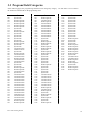
4208 ………………………………………………. p.39
5882 Wireless Expansion …………………….. p.41
5804 Four Button Remote …………………….. p.43
5804 Bi Directional Wireless Remote ……..… p.44
5827 Wireless Keypad ………………………… p.46
5827 Bi Directional Wireless Keypad ………. p.47
4285 Voice Interactive Phone Module ………. p.48
4204 Relay Programming …………………….. p.49
Garage Door Setup ……………………………. p.51
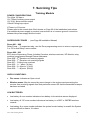
7. Servicing Tips ……………………………………. p.52
Vista 120 Training Guide
2
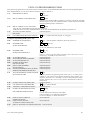
1. Basic Panel Features
VISTA 120
Ø 9 Hardwired Zones – standard
Ø Expands to 128 Zones
− Hardwired
− Multiplex
− Wireless (5800 Series)
Ø 8 Partitions
− 3 Common Areas
Ø 150 User Codes with 7 Authority Levels (per partition)
Ø Access Control
− Master Console Option
− 32 Relay Outputs
− Real Time Scheduling
− Full Alpha Console with Macro keys
Ø 4285 VIP Telephone Module
Ø 224 Event Memory
Ø Securitel Compatible using Ademco Unistu
Ø Programmable via key pad, Remote downloading and Direct connection
Vista 120 Training Guide
3
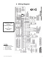
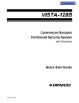
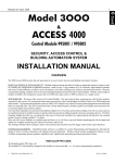
2. Wiring Diagram
Latching Strobe
requires
STROB MODULE
or
Relay Output
Module
NOTES:
1. No Wiring to run
behind Circuit Board
2. Run Earth Wire
3. Max 16Consoles
4. Insert NCU Board
Vista 120 Training Guide
4
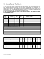
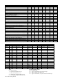
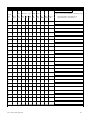
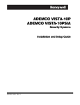
3.6 System Layout Worksheets
As with any security system, you should first define the installation. This includes determining how
many partitions will be used, how many zones per partition, and how many users per partition. You
will also need to determine what peripheral devices will be needed, and basic system options such as
exit/entry delays, etc. The control panel itself should be located in an area that will facilitate wire runs
to all partitions, and will allow access to power and telephone circuits.
To help you layout a partitioned system, use the following worksheet. This will further simplify
the programming process.
PARTITIONS
Partition #
Descriptor
(4 char max)
Prim.
Sub. #
Sec.
Sub. #
Alpha Default Message
(32 character maximum)
Partition 1
Partition 2
Partition 3
Partition 4
Partition 5
Partition 6
Partition 7
Partition 8
Zone 7 Keyswitch Arming Partition Assignment (1-8):
Wireless Keypad Partition Assignment (1-8):
Voice Module Partition Assignment (1-8):
Use Partition Descriptor (yes/no)?
Common Area 1 Partition Assignment (1-8):
Common Area 2 Partition Assignment (1-8):
Common Area 3 Partition Assignment (1-8):
COMMUNICATION OPTIONS BY PARTITION (enter yes/no)
Option
part 1
part. 2
part. 3
part. 4
part. 5
part. 6
part. 7
part. 8
Intermittent Sensor Suppression Count
(00-15; 00=no suppression)
Cancel Report After Disarm
Dialler Reports for Panic (* + 1)
Dialler Reports for Panic (# + 3)
Dialler Reports for Panic (* + #)
Dialler Reports for Duress
Burglary Alarm Communications Delay (16 sec.)
Vista 120 Training Guide
5
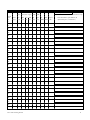
SYSTEM DEFINITIONS BY PARTITION (enter values or yes/no)
Option
part 1
part. 2
part. 3
part. 4
part. 5
part. 6
part. 7
Entry Delay #1 (15-225 seconds):
Exit Delay #1 (15-225 seconds):
Entry Delay #2 (15-225 seconds):
Exit Delay #2 (15-225 seconds):
Quick Arming
Multiple Alarms per Arming
Keypad Panic for zone 995 (* + 1)
Keypad Panic for zone 996 (# + 3)
Keypad Panic for zone 999 (* + #)
Allow Sign-on (GOTO function)
Non-Bypassable Zone*
Sounder Timeout for Siren (2 min. increments)
Keypad Annunciation During Entry**
Keypad Annunciation During Exit
Confirmation of Arming Ding for Bell/Siren
Chime on Bell/Siren
Access Control Relay (field 1*76)
Affects Common Area 1 (check partitions that apply)
Årms Common Area 1 (check partitions that apply)
Affects Common Area 2 (check partitions that apply)
Årms Common Area 2 (check partitions that apply)
Affects Common Area 3 (check partitions that apply)
Årms Common Area 3 (check partitions that apply)
Displays Fire Alarms of Other Partitions
Displays Burg & Panic Alarms of Other Partitions
Displays Troubles of Other Partitions
*Can be any zone 1-128. **no = 3 beeps
yes = continuous
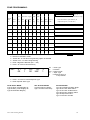
DEVICES (Keypads, 4204, etc.)
Device
Address
Type
Home
Partition
Sounder
Option
Supervised
CF?
00
01
02
03
04
05
06
07
08
09
10
11
12
13
14
15
Device
Address
Type
Home
Partition
Sounder
Option
Supervised
CF?
16
17
18
19
20
21
22
23
24
25
26
27
28
29
30
Type:
0 = device not used
1 = alpha keypad (address 00-30)
3 = RF receiver (address 01-07)
4 = Output Relay module (address 00-15)
5 = Voice Module (address 04 factory set)
Vista 120 Training Guide
Keypad Sounder Options:
00 = no suppression
01 = suppress arm/disarm and entry/exit beeps
02 = suppress chime mode beeps only
03 = suppress arm/disarm, entry/exit and chime mode beeps
part. 8
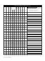
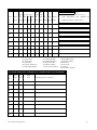
ZONE DEFINITIONS FOR ZONES 1-24
devices
Zone
No.
1
Zone
Type
Parti-
DIP DIP
†
RF Trans. Type RPM RPM
tion
(1-8)
RF
(3)
UR
(4)
BR
(5)
left
loop
right
loop
† Enter loop number on module Must be 1
for basic wired, serial numbered, and DIP left loop
Ser. Basic Report
RPM † Wired Code
Zone Information (part numbers) &
Alpha Descriptor (3 words max.)
2
3
4
5
6
7
8
9
10
11
12
13
14
15
16
17
18
19
20
21
22
23
24
Vista 120 Training Guide
7
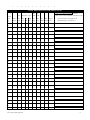
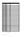
ZONE DEFINITIONS FOR ZONES 25-48
DIP
devices
Zone
No.
25
Zone
Type
DIP
Parti-
RF Trans. Type† RPM RPM
tion
(1-8)
RF
(3)
UR
(4)
BR
(5)
left
loop
right
loop
† Enter loop number on module
Must be 1
for basic wired, serial numbered, and DIP left loop
Ser. Basic Report
RPM † Wired Code
Zone Information (part numbers) &
Alpha Descriptor (3 words max.)
26
27
28
29
30
31
32
33
34
35
36
37
38
39
40
41
42
43
44
45
46
47
48
Vista 120 Training Guide
8
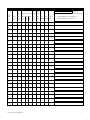
ZONE DEFINITIONS FOR ZONES 49-72
DIP
devices
Zone
No.
49
Zone
Type
DIP
Parti-
RF Trans. Type† RPM RPM
tion
(1-8)
RF
(3)
UR
(4)
BR
(5)
left
loop
right
loop
† Enter loop number on module Must be 1
for basic wired, serial numbered, and DIP left loop
Ser. Basic Report
RPM † Wired Code
Zone Information (part numbers) &
Alpha Descriptor (3 words max.)
50
51
52
53
54
55
56
57
58
59
60
61
62
63
64
65
66
67
68
69
70
71
72
Vista 120 Training Guide
9
ZONE DEFINITIONS FOR ZONES 73-96
devices
Zone
No.
73
Zone
Type
Parti-
DIP DIP
†
RF Trans. Type RPM RPM
tion
(1-8)
RF
(3)
UR
(4)
BR
(5)
left
loop
right
loop
† Enter loop number on module Must be 1
for basic wired, serial numbered, and DIP left loop
Ser. Basic Report
RPM † Wired Code
Zone Information (part numbers) &
Alpha Descriptor (3 words max.)
74
75
76
77
78
79
80
81
82
83
84
85
86
87
88
89
90
91
92
93
94
95
96
Vista 120 Training Guide
10
ZONE DEFINITIONS FOR ZONES 97-120
DIP
devices
Zone
No.
97
Zone
Type
DIP
Parti-
RF Trans. Type† RPM RPM
tion
(1-8)
RF
(3)
UR
(4)
BR
(5)
left
loop
right
loop
† Enter loop number on module Must be 1
for basic wired, serial numbered, and DIP left loop
Ser. Basic Report
RPM † Wired Code
Zone Information (part numbers) &
Alpha Descriptor (3 words max.)
98
99
100
101
102
103
104
105
106
107
108
109
110
111
112
113
114
115
116
117
118
119
120
Vista 120 Training Guide
11
ZONE DEFINITIONS FOR ZONES 121-128
DIP
Zone
Zone
Partition
RF Trans. Type†
RF
UR BR left
No.
121
Type
(1-8)
(3)
(4)
(5)
DIP
† Enter loop number on module
RPM RPM
Must be 1
for basic wired, serial numbered, and DIP left loop devices
right Ser.
Basic
Report
loop loop RPM† Wired Code
Zone Information (part numbers) &
Alpha Descriptor (3 words max.)
122
123
124
125
126
127
128
Zone Types:
00=zone not used
01=entry/exit 1
02=entry/exit 2
03=perimeter
04=interior (follower)
05=day/night burglary
06=24 hour silent
07=24 hour audible
08=24 hour auxiliary
09=supervised fire
10=interior (delay)
16=Fire w/Verification
17=Fire Supervisory
18=Fire Supervisory
19=24 hour trouble
20=arm stay
21=arm away
22=disarm
23=no alarm response
ZONE DEFINITIONS FOR DEVICE SUPERVISORY ZONES 800-809
Zone
No.
800
Zone
Type
Partition
(1-8)
Report
Code
Alpha Descriptor (3 words max.)
801
802
803
804
805
806
807
808
809
Vista 120 Training Guide
12
ZONE DEFINITIONS FOR DEVICE SUPERVISORY ZONES 810-831
Zone
No.
810
Zone
Type
Partition
(1-8)
Report
Code Alpha Descriptor (3 words max.)
811
812
813
814
815
816
817
818
819
820
821
822
823
824
825
826
827
828
829
830
831
Zone Types:
05=day/night burglary
19=24 hour trouble
Vista 120 Training Guide
13
ZONE DEFINITIONS FOR KEYPAD PANIC/MISC. ZONES 988-999
Zone
No.
Zone
Type
Partition
(1-8)
Report
Code
Alpha Descriptor (3 words max.)
988
2 nd rcvr
990
1 st rcvr
992
duress
995
panic
996
panic
997
poll short
999
panic
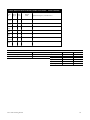
PRINTER OPTIONS
12 or 24 hour Time format
Printer On-Line (yes/no)
1200 or 300 baud Printer Baud Rate
Vista 120 Training Guide
Option
Alarm
Trouble
Bypass
Open/Close
System
Test Report
EVENT LOG TYPES
No (4)
Yes (4)
14
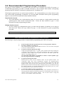
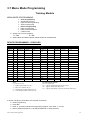
3.2 Recommended Programming Procedure
The purpose of this document is to provide a quick and easy way to program your VISTA-120 system. A
recommended programming procedure is included, followed by a list of program fields with the corresponding
program group they belong to (Systemwide, partition-specific, scheduling, etc.).
Following the program forms are system layout worksheets. We recommend that you use these sheets to plan
your system before programming is performed. If you need further information about specific programming
options, see the VISTA-120 INSTALLATION INSTRUCTIONS.
Single Partition System
• The system default is for a single partition system. If you are setting up a single -partition system, the
partition-specific fields become Systemwide fields. Follow the steps outlined on page 3 of this
document for proper programming procedure.
Multiple -Partition System
• If you are setting up a multi-partition system, you must enter the number of partitions you are using in
data field 2*00. Follow the steps outlined on page 3 of this document for proper programming
procedure.
Make sure that one keypad is connected to the control and is set to device address "00."
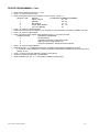
RECOMMENDED PROGRAMMING PROCEDURE
The following is a step-by-step procedure recommended for programming your VISTA-120 system.
Vista 120 Training Guide
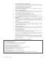
1.
Set the keypads (and other peripheral devices) to the appropriate addresses.
2.
Set factory defaults by pressing *97.
This will automatically enable keypad addresses 00-03, so be sure at least one keypad
is set to one of these addresses.
3.
Program Systemwide (global) data fields.
Using the programming form as a guide, enter program mode and program all
systemwide programming fields. These options affect the entire system, regardless
of partitions. They include control options, downloader and dialler options, RF
options, event logging options, etc.
Note that field 2*00 (number of partitions) & field 1*32 (RF expander type)
must be programmed before continuing.
4.
Program partition-specific fields.
Partition-specific fields can have different values for each partition. When the
systemwide fields have been programmed, program all partition-specific
programming fields by first pressing *91 to select a partition (while still in data field
program mode). Then enter the first partition-specific field number *09. The next
partition-specific field will automatically be displayed when you are finished entering
the value for field *09. To program the fields for the next partition, press *91, enter
the desired partition number, then enter field *09.
5.
Use #93 Menu Mode for device programming.
Refer to the DEVICE PROGRAMMING section of the Installation Instructions to
assign keypad ID numbers and default partitions for each keypad, and to selectively
suppress certain keypad sounding options. Also use this mode to assign RF
receivers, relay modules, and the VIP module.
15
6.
Use #93 Menu Mode for zone programming.
Refer to the ZONE PROGRAMMING section of the Installation Instructions to
program zone response types, assign right loop zones and wireless zones, assign
zones to partitions, and to program alarm report codes.
7.
Use #93 Menu Mode for programming relays.
Refer to the RELAY PROGRAMMING section of the Installation Instructions to
program desired relay operation.
8.
Program Communication options.
Refer to the COMMUNICATION PROGRAMMING section of the Installation
Instructions to load communication defaults and to program related fields. Then use
#93 mode to program report codes if necessary.
9.
Use #93 Menu Mode for programming alpha descriptors.
Refer to the ALPHA PROGRAMMING section of the Installation Instructions to
enter zone and partition descriptors and a custom installer's message.
10.
Use #93 Menu Mode for programming relay voice descriptors and custom word
substitutes.
Refer to the RELAY VOICE DESCRIPTORS section of the Installation Instructions
for further instructions for programming relay descriptors to be annunciated by the
4285 VIP module, as well as the CUSTOM INDEX section for custom word
substitutes.
11.
Use #80 Mode for programming schedules.
Refer to the SCHEDULING section of the Installation Instructions to program
open/close schedules, temporary and holiday schedules, limitation of access
schedules, and time driven events.
12.
Define user access codes.
Refer to SECURITY ACCESS CODES section of the Installation Instructions to
program authority level, O/C reporting option, partition assignments, and wireless
key assignments for each user.
13.
Exit Programming Mode
Exit programming mode by pressing either *98 or *99. A second entry of *99 is
required if the exit is being done from fields 1*00 and above.
To prevent re-access to Programming mode using the Installer's code, use *98. The
only way to re-access Programming mode is by depressing both the [*] and [#] keys
at the same time within 30 seconds of power up.
Exiting by using *99 always allows reentry into Programming mode using the
Installer's code. Either way of exiting will allow access via downloading. Note that if
local programming lockout is set via downloading, programming mode cannot be
entered at the keypad.
SUMMARY OF PROGRAMMING COMMANDS
• To enter program mode, enter installer code + [8] + [0] + [0] + [0]
• To set standard defaults, press *97
• To set communication defaults, press *94 + one of the following:
*82=Ademco Expanded High Speed; *83=Ademco Contact ID
• To change to next page of program fields, press *94
• To return to previous set of fields, press *99
• To erase account & phone number field entries, press [*] + field number + [*]
• To assign zone descriptors, press #93 + follow menu prompts
• To add custom words, press #93 + follow menu prompts
• To enter Installer's Message, press #93 + follow menu prompts
• To exit program mode, press *99 OR *98: *99 allows re -access to programming mode by installer code.
*98 prevents re-access to programming mode by installer code.
Vista 120 Training Guide
16
Vista 120 Training Guide
17
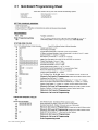
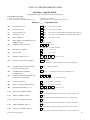
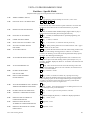
3.3 Program Field Categories
In the following pages, the programming fields have been arranged by category. Use this index to cross reference
the numerical ordered fields on the programming form.
Field
*00
*06
*07
*09
*10
*11
*12
*13
*14
*15
*16
*17
*18
*19
*20
*21
*22
*23
*24
*25
*26
*27
*28
*29
*30
*31
*32
*33
*34
*35
*36
*37
*38
*39
*40
*41
*42
*43
*44
*45
*46
*47
*48
*49
*50
*51
*52
*53
*54
*79
*80
*83
*84
*85
Group
Systemwide
Systemwide
Systemwide
Partition-Specific
Partition-Specific
Partition-Specific
Partition-Specific
Partition-Specific
Systemwide
Systemwide
Partition-Specific
Systemwide
Systemwide
Systemwide
Systemwide
Systemwide
Partition-Specific
Partition-Specific
Systemwide
Systemwide
Communications
Commu nications
Systemwide
Partition-Specific
Communications
Communications
Partition-Specific
Communications
Communications
Systemwide
Systemwide
Systemwide
Partition-Specific
Partition-Specific
Communications
Systemwide
Communications
Communications
Communications
Communications
Communications
Communications
Communications
Communications
Communications
Communications
Communications
Communications
Communications
Communications
Communications
Communications
Partition-Specific
Partition-Specific
Vista 120 Training Guide
Field
*86
*87
*88
*89
*90
1*01
1*02
1*03
1*04
1*05
1*06
1*07
1*08
1*09
1*10
1*11
1*12
1*13
1*14
1*15
1*16
1*17
1*18
1*19
1*20
1*21
1*22
1*23
1*24
1*25
1*26
1*28
1*29
1*30
1*31
1*32
1*33
1*34
1*35
1*36
1*37
1*38
1*39
1*40
1*41
1*42
1*43
1*44
1*45
1*46
1*47
1*48
1*49
1*52
Group
Systemwide
Partition-Specific
Partition-Specific
Communications
Partition-Specific
#93 Menu Mode
#93 Menu Mode
#93 Menu Mode
#93 Menu Mode
#93 Menu Mode
#93 Menu Mode
#93 Menu Mode
#93 Menu Mode
#93 Menu Mode
Systemwide
Systemwide
Partition-Specific
Partition-Specific
Systemwide
Partition-Specific
Partition-Specific
Systemwide
Partition-Specific
Partition-Specific
Systemwide
Systemwide
Systemwide
Systemwide
Systemwide
Systemwide
Partition-Specific
Systemwide
Systemwide
Systemwide
Systemwide
Systemwide
Communications
Communications
Communications
Communications
Communications
Communications
Communications
Communications
Partition-Specific
Communications
Partition-Specific
Systemwide
Partition-Specific
Systemwide
Partition-Specific
Systemwide
Systemwide
Partition-Specific
Field
1*53
1*55
1*56
1*57
1*58
1*60
1*66
1*67
1*70
1*71
1*72
1*73
1*74
1*75
1*76
2*00
2*01
2*02
2*05
2*06
2*07
2*08
2*09
2*10
2*11
2*13
2*14
2*18
2*19
2*20
2*21
2*22
2*23
2*24
Group
Systemwide
Systemwide
Systemwide
Systemwide
Systemwide
Systemwide
Systemwide
Systemwide
Systemwide
Systemwide
Systemwide
Systemwide
Systemwide
Systemwide
Partition-Specific
Systemwide
Systemwide
Systemwide
Partition-Specific
Partition-Specific
Partition-Specific
Partition-Specific
Partition-Specific
Partition-Specific
Systemwide
Communications
Communications
Partition-Specific
Partitioning
Partition-Specific
Systemwide
Partition-Specific
Partition-Specific
Partition-Specific
18
3.4 Programming Form
Partition-Specific fields are programmed separately for each partition (shown as shaded fields). See the PARTITION-SPECIFIC section
for programming these fields. Standard default (*97) values are shown in brackets [ ], otherwise default = 0.
NOTE: New fields (phase 2) are indicated by dotted underlined field numbers and titles.
*00
INSTALLER CODE
*01
INSTALLER CODE RESTRICTION
[0] 1 = Yes; 0 = No
*03
FINAL CONTACT SET (partition-specific)
[0] 1 = Yes; 0 = No
*04
AUTOBYPASS EXIT ROUTE FAULTS
[0]
(partition-specific)
| | |
[4140]
1 = Yes; 0 = No
*05
ARM WITH LOW BATTERY
[0] 1 = Yes; 0 = No
*06
ZONE TYPE 5 ALWAYS ALARM
[0] 1 = Yes; 0 = No
*07
ALLOW ARMING WITH
[0]
FAULTS IN EXIT ROUTE
*08
SELF ACTIVATING SIREN OUTPUT
*09
*10
*11
*12
*13
ENTRY DELAY #1
EXIT DELAY #1
ENTRY DELAY #2
EXIT DELAY #2
BELL TIMEOUT
*14
ZONE 9 RESPONSE TIME
Enter 4 digits, 0-9
1 = Yes; 0 = No
[0] 1 = Yes ; 0 = No
Partition-Specific
Partition-Specific
Partition-Specific
Partition-Specific
Partition-Specific
[0]
1 = fast response mode (10msec); 0 = normal response, 350msec
*15
KEYSWITCH ASSIGNMENT
[0]
1-8; 0=disable
Enter partition in which keyswitch used.
*16
BELL/SIREN CONFIRMATION OF
ARMING DING
*17
AC MAINS LOSS KEYPAD
SOUNDING
Partition-Specific
[0]
1=yes; 0=no
*18
MAINS PRESENCE DISPLAY
[0] 1 = Yes
*19
RANDOMISE AC MAINS
[0] ( 1 = recommended )
LOSS REPORT
*20
TELEPHONE MODULE
PHONE CODE
*21
PREVENT FIRE TIME-OUT
0 = No
1=10-40 min; 0=normal report
about 2 min. after AC loss
|
|
[00] [11]
Enter 01 - 09 for first digit; enter 11 for "*" or 12 for "#" for second digit.
[0]
1 = disable (no timeout); 0 = normal burglary alarm sounder duration
(programmed in partition-specific field *13)
*22
*23
KEYPAD PANIC ENABLE
MULTIPLE ALARMS
Vista 120 Training Guide
Partition-Specific
Partition-Specific
19
VISTA 120 PROGRAMMING FORM
Some fields are programmed for each partition (shown as shaded fields). See the PARTITION-SPECIFIC section for programming these
fields. Standard default (*97) values are shown in brackets [ ], otherwise default = 0.
*24
IGNORE EXPANSION
ZONE TAMPER
*25
[0]
1=Ignore; 0=Enable tamper for RF and RPMs.
BURG.TRIGGER FOR
RESPONSE TYPE 8
*26
INTELLIGENT TEST REPORTING
*27
TEST REPORT INTERVAL
[1]
1=enable; 0=disable
[0] 1=yes, (no report sent if any other report was recently sent); 0=no.
| |
[024]
001-999; 000=no report; Enter interval in hours.
*28
POWER UP IN PREVIOUS STATE
*29
QUICK ARM
*30
MULTIFREQUENCY OR
PULSE DIAL
*31
PABX ACCESS CODE
[1]
1=yes; 0=no
Partition-Specific
[0] ( 1 = Recommended )
1=Multifrequency (DTMF); 0=Pulse Dial
|
|
|
|
Enter 00-09; B-F (11-15)
*32
PRIMARY SUBS. ACCT #
*33
PRIMARY PHONE NUMBER
Partit ion-Specific
Enter 0-9 for each digit. Enter #11 for *, #12 for #, #13 for 2 second pause
*34
SECONDARY PHONE NUMBER
Enter 0-9 for each digit. Enter #11 for *, #12 for #, #13 for 2 second pause
*35
DOWNLOAD PHONE No.
Enter 0-9 for each digit. Enter #11 for *, #12 for #, #13 for 2 second pause
*36
DOWNLOAD ID No.
|
|
|
|
|
|
|
|
Enter 00-09; A-F (10-15) [15 15 15 15 15 15 15 15]
*37
DOWNLOAD COMMAND ENABLES
0
[1]
Dialler System Restrict Remote Remote
Remote Upload Download
Shutdwn Shutdwn Access
Bypass Disarm
Arm
Prog
Prog
See field 1*53 for Callback disable option; 1=enable; 0=disable
† Restrict Download Access When Armed: Can only arm unarmed partitions,
upload the programme/ event log, command relays, and request status
*38
*39
PREVENT ZONE XXX BYPASS
ENABLE OPEN/CLOSE REPORT
FOR INSTALLER CODE
*40
OPEN/CLOSE REPORT
FOR KEYSWITCH
1=enable; 0=disable
NORMALLY CLOSED or EOLR
(Zones 2-8)
1=N.C. loops; 0=EOLR supervision
*41
*42
SUPPRESS FIRE ALARM RELAY
Vista 120 Training Guide
Partition-Specific
Partition-Specific
[0]
[1]
1= suppress fire alarm relay on 4204/Powerline Carrier Device relays
0= 4204/Powerline Carrier Device fire alarm relay activates on fire alarms
20
VISTA 120 PROGRAMMING FORM
Some fields are programmed for each partition (shown as shaded fields). See the PARTITION-SPECIFIC section for programming these
fields. Standard default (*97) values are shown in brackets [ ], otherwise default = 0.
*43
*44
SUPPRESS RF SIREN ACTIVATION
FOR FIRE ALARMS
RING DETECTION COUNT
[0]
1= suppress wireless siren (e.g. 5840) activation on fire alarms
0= wireless siren sounds for fire alarms
|
[00]
01-14; 15=answering machine/fax bypass; 00=no detection.
*45
PRIMARY FORMAT
[0]
0=Low Speed; 1=Contact ID; 2=Ademco Exp. High Speed; 3=Ademco Express
*46
LOW SPEED FORMAT (Primary)
[0]
0=Ademco Low Speed; 1=Sescoa/Radionics
*47
SECONDARY FORMAT
*48
LOW SPEED FORMAT (Sec.)
[0]
0=Low Speed; 1=Contact ID; 2=Ademco Exp. High Speed; 3=Ademco Express
[0]
0=Ademco Low Speed; 1=Sescoa/Radionics
*49
CHECKSUM VERIFICATION
[0] [0] Prim
*50
SESCOA/RADIONICS SELECT
[0]
*51
DUAL REPORTING
[0]
Sec
1=yes; 0=no
1=Sescoa; 0=Radionics
1=yes; 0=no; If used with Spilt Reporting "1" option (1*34), alarms and alarm
restores go to both primary & secondary numbers, while all other reports go to
secondary only. If used with Split Reporting "2" option, alarms and alarm
restores go to both, open/close and test messages go to secondary only, while all
other reports go to primary.
*52
STANDARD/EXPANDED REPORT
FOR PRIMARY
*53
[0]
Alarm Rstr
Bypass Trbl
Opn/Cls
Low Bat
0=standard; 1=expanded; Note: Expanded overrides choices in 4+2 format.
STANDARD/EXPANDED REPORT
FOR SECONDARY
*54
MAX. No. OF DIALLER ATTEMPTS
*55
TELEPHONE SYSTEM SELECT
† options 01
[0]
Alarm Rstr
Bypass Trbl
Opn/Cls
Low Bat
0=standard; 1=expanded; Note: Expanded overrides choices in 4+2 format.
[8]
Enter 1-8.
|
[00]
00= SECURITEL
01=
Australia †
*56
CONTACT ID DATA ON KEYPAD
BUS FOR ALT. COMM. Media
Reporting Instead Of Digicom
[0]
1= Yes
0= No
*57
CONTACT ID DATA ON KEYPAD
BUS FOR BACK-UP Alt. Comm.
Media Reporting If Digicom Fails
[0]
1= Yes
0= No
*58
SELECTION OF CONTACT ID
MESSAGE DATA ON KEYPAD
BUS FOR SUBSCRIBER ID#1
Vista 120 Training Guide
Alarms
Troubles
[0][0][0][0][0][0]
1=Yes; 0=No
Bypasses
Open/
Close
System
Conditions
Test
Reports
21
VISTA 120 PROGRAMMING FORM
Some fields are programmed for each partition (shown as shaded fields). See the PARTITION-SPECIFIC section for programming these
fields. Standard default (*97) values are shown in brackets [ ], otherwise default = 0.
*59
SELECTION OF CONTACT ID
MESSAGE DATA ON KEYPAD
BUS FOR SUBSCRIBER ID#2
Alarms
*60
VERIFIED ALARM REPORT
ENABLE
[0]
1= Yes (Swedish requirement)
0= No
*61
ROBOFON VERSION OF
CONTACT ID
[0]
0= Yes (Swedish requirement),
0= No
*79
ZONE TYPE RESTORE ENABLES
FOR ZONE TYPES 1-8
*80
FIRST TEST REPORT TIME
Bypasses
Open/
Close
System
Conditions
Test
Reports
[0]
1
2
3
1=enable; 0=disable
ZONE TYPE RESTORE ENABLES
FOR TYPES 9/10
*83
Troubles
[0][0][0][0][0][0]
1=Yes; 0=No
4
5
6
7
8
[0]
9
10
1=enable; 0=disable
|
|
|
[Day 00; hour 12; min 00] Days 01-07 Hours 00-23 Min 00-59;
00 in all boxes=instant (Day 01= Monday)
*84
INTERMITTENT SENSOR
SUPPRESSION
Partition-Specific
*85
ENABLE DIALLER REPORTS [0]
FOR PANICS & DURESS
Partition-Specific
*86
REPORT/LOG ZONE TYPE 23
*87
ENTRY WARNING
Partition-Specific
*88
BURG. ALARM COMM. DELAY
Partition-Specific
*89
RESTORE REPORT TIMING
[0]
1=yes; 0=no
[0] 0=Instant; 1=After bell timeout if zone is restored; 2=when system is
disarmed.
*90
SECONDARY SUBS. ACCT.#
Partition-Specific
1*00
CONTACT ID REPORTING IN
ASCII THROUGH PRINTER PORT
[0]
1= Yes
ASCII CONTACT ID REPORTING
WITH OR WITHOUT ACK
[0]
1= ACK not required
1*01
0= No, event log usage
0= ACK required
1*02
ASCII CONTACT ID BAUD RATE
[0] 0= 1200 1= 2400 2= 4800
1*05
BYPASS ENABLE FOR FIRE ZONES
[0]
1=yes, allow bypass of fire zones; 0= fire zones cannot be bypassed
1*06
SUPPRESS ALL KEYPAD DISPLAYS
WHEN SYSTEM IS ARMED
Vista 120 Training Guide
[0]
0= Yes; 0= No
22
VISTA 120 PROGRAMMING FORM
Some fields are programmed for each partition (shown as shaded fields). See the PARTITION-SPECIFIC section for programming these
fields. Standard default (*97) values are shown in brackets [ ], otherwise default = 0.
1*07
CHECK OR TROUBLE DISPLAY
1*08
SUPPRESS USE OF "ARMED"
LED ON KEYPADS
[0] 0=check; 1=trouble
(For countries where Red is only for alarm)
[0]
1= Yes
0= No
1*09
SUPPRESS KEYPAD ARMING
STATUS INDICATIONS WHEN
SYSTEM IS ARMED
[0]
1= Yes
0= No
1*10
FIRST TO ALARM DISPLAY LOCK
[0]
1=yes; 0=no
1*11
COMMON AREA 1 PARTITION
[0]
Enter the "common area 1" partition (1-8)
1*12
AFFECTS COMMON AREA 1
Partition-Specific
1*13
ARMS COMMON AREA 1
Partition-Specific
1*14
COMMON AREA 2 PARTITION
1*15
AFFECTS COMMON AREA 2
Partition-Specific
1*16
ARMS COMMON AREA 2
Partition-Specific
1*17
COMMON AREA 3 PARTITION
1*18
AFFECTS COMMON AREA 3
Partition-Specific
1*19
ARMS COMMON AREA 3
Partition-Specific
1*20
AUTOBYPASS FAULTED
[0]
Enter the "common area 2" partition (1-8)
[0]
Enter the "common area 3" partition (1-8)
[0]
EXIT ROUTE ZONES
0=No, 1=Bypass E/E and Interior zones faulted after exit delay. (Australian
requirement)
1*21
EXIT DELAY RESET
[0] 0=No; 1=Resets Exit Delay to 60 seconds after zone is closed.
1*22
CROSS-ZONING PAIR ONE
| |
| |
Enter 3-digit zone numbers to be linked so that both must fault within
a five minute period to cause an alarm.
1*23
CROSS-ZONING PAIR TWO
| |
| |
Enter 3-digit zone numbers to be linked so that both must fault within
a five minute period to cause an alarm.
1*24
CROSS-ZONING PAIR THREE
| |
| |
Enter 3-digit zone numbers to be linked so that both must fault within
a five minute period to cause an alarm.
1*25
CROSS-ZONING PAIR FOUR
| |
| |
Enter 3-digit zone numbers to be linked so that both must fault within
a five minute period to cause an alarm.
1*26
PANIC BUTTON OR SPEED KEY
1*27
FIELD 1*31 TRANS. CHECK-IN
SUPERVISION INTERVAL TO BE
MULTIPLE OF 1 HOUR
INSTEAD OF 2 HOURS
Vista 120 Training Guide
partition-specific
[0]
1 = 1 hour (must be 1 hour for CENELEC compliance)
0 = 2 hours
23
VISTA 120 PROGRAMMING FORM
Some fields are programmed for each partition (shown as shaded fields). See the PARTITION-SPECIFIC section for programming these
fields. Standard default (*97) values are shown in brackets [ ], otherwise default = 0.
1*28
RF TX LOW BATTERY SOUND
1*29
RF TX LOW BATTERY REPORT ENABLE
1*30
RF RCVR CHECK-IN INTERVAL
1*31
RF TRANSMITTER
CHECK-IN INTERVAL
[0]
[0]
1=enable; 0=disable
|
[06]
02-15 times 2 hours; 00 disables supervision
|
[12]
02-15 times 2 hours; 00 disables transmitter supervision
1*32
RF RECEIVER TYPE
[0]
1*33
MULTIFREQUENCY with
[0]
PULSE DIAL BACKUP
1*34
1=immediate; 0=when disarmed
1=4281; 2=5881/5882
1=enable; 0=disable
COMM. SPLIT REPORT SELECTION
[0]
0=no; 1=alarms and alarm restores primary, others secondary; 2=open/close, test secondary, others primary; See T51 for
comments if using with dual reporting.
1*35
LOW BATTERY TEST INTERVAL
[0]
1 = 1.5 second test every 50 seconds
0 = 13 second test every 4 minutes
1*36
CPU FAIL TRIGGER OUTPUT
[0]
1 = yes, Output trigger 2 on J7 to be CPU fail output, overriding any
other selection for Output 2 (CENELEC requirement)
0 = no, normal use for Output 2
1*37
TLM INPUT ON ZONE 9
[0]
1 = yes, telephone line fault monitor output to be fed into zone 9
0 = no, normal use for zone 9
1*38
USER RESET OF TAMPER ALARMS
INSTEAD OF INSTALLER ONLY RESET
1*39
MAX. NUMBER OF ZONES THAT
CAN BYPASSED PER PARTITION
(partition-specific)
1*41
BYPASS/UNBYPASS ZONES
WHEN ARMED
1*42
1 = yes 0 = no
USER BYPASS OF TAMPER
FAULTS INSTEAD OF
INSTALLER ONLY BYPASS
1*40
[0] ( 1 = Recommended )
CALL WAITING DEFEAT
[0] ( 1 = Recommended )
1 = yes
0 = no
|
[00]
01-15, 00 = no restriction
[0]
1=Yes; 0=No.
[0]
1=Yes; 0=No.
1*43
PERM. KEYPAD BACKLIGHT
1*44
WIRELESS KEYPAD
1*45
TAMPER DETECT ENABLE
EXIT DELAY SOUNDING
1*46
AUXILIARY OUTPUT MODE
Partition-Specific
[1] (Locks out keypad after 20 key sequential key presses)
1=enable; 0=disable.
Partition-Specific
[0]
0 = ground start output; 1 = open/close trigger; 2 = keypad-like
sounding 3 = AAV module is being used
Vista 120 Training Guide
24
VISTA 120 PROGRAMMING FORM
Some fields are programmed for each partition (shown as shaded fields). See the PARTITION-SPECIFIC section for programming these
fields. Standard default (*97) values are shown in brackets [ ], otherwise default = 0.
1*47
CHIME ON BELL/SIREN
1*48
WIRELESS KEYPAD ASSIGNMENT
Partition-Specific
[0]
0=disable; enter partition in which RF keypad used, 1-8.
1*49
SUPPRESS TX SUPERVISION
SOUND
1*50
No. SECONDS ADDED PER DAY
[1]
1=disable; 0=enable
[0]
00-30 = number of seconds needed to be added per day for clock
1*51
No. SECONDS REMOVED PER DA Y
1*52
SEND CANCEL IF ALARM + OFF
1*53
DOWNLOAD CALLBACK
[0]
00-30 = number of seconds needed to be removed per day for clock
Partition-Specific
[0]
1=callback not required; 0=callback required
1*54
INTERNAL CLOCK SYNC.
[0] 1 = use internal crystal for real-time clock; 0=use AC sync for clock
1*55
INTERNATIONAL DATE FORMAT
[1]
1=DDMMYY; 0=MMDDYY
1*56
AC 60Hz/50Hz
[1]
1 = 50Hz; 0 = 60Hz (Aust. Requirement 50Hz)
1*57
5800 RF BUTTON GLOBAL ARM
[0]
1 = yes; 0 = no
1*58
5800 RF BUTTON FORCE ARM
[0]
Enter "1" to enable. If a zone is faulted after pressing button, keypad will beep
once. User should press button again within 4 sec. to force bypass those
zones. Enter "0" to disable.
1*59
SUPRESS STATUS LED OUTPUT
WHEN ZONE 7 KEYSWITCH
ENABLED / RETAIN VOLTAGE
TRIGG. OUTPUTS
[0]
1 =yes
0 = no
1*60
ALARM VERIFICATION
[0] Enter 1 If alarm verification is being used; Enter 0 if it is not.
1*61
DISPLAY TAMP[e]R
[0]
Enter 1 to display "TAMPR" upon tamper conditions;
Enter 0 to display "CHECK" or "TRBL" depending on state of field 1*07
1*62
TAMPER DETECT IN TEST MODE
[0]
Enter 1 to terminate Test mode upon tamper condition;
Enter 0 to ignore tamper conditions during Test mode (displays "FAULT")
1*66
SILENCE SOUNDERS DURING AAV
1*67
VIDEO ALARM VERIFICATION
1*70
EVENT LOG TYPES
[0]
[0]
1=AAV in use; 0=No
1=Yes; 0=Audio Alarrm Verification
Alrm
Chck
Byps
1=enable; 0=disable
1*71
12/24 HOUR TIME STAMP FORMAT
[0]
1*72
EVENT LOG PRINTER ON-LINE
[0]
O/C
Syst
Test Rpt
1=24 hour; 0=12 hour
1=enable; 0=disable
Vista 120 Training Guide
25
VISTA 120 PROGRAMMING FORM
Some fields are programmed for each partition (shown as shaded fields). See the PARTITION-SPECIFIC section for programming these
fields. Standard default (*97) values are shown in brackets [ ], otherwise default = 0.
1*73
PRINTER BAUD RATE
[0]
1=300; 0=1200
1*74
RELAY TIMEOUT XXX MINUTES
| |
[000]
Enter the relay timeout, 0-127 in multiples of 2 minutes, desired for #80 Menu
Mode time driven event relay command numbers "04/09" and #93 Menu Mode
Relay Programming output command "56".
1*75
RELAY TIMEOUT YYY SECONDS
| |
[000]
Enter the relay timeout, 0-127 seconds, desired for #80 Menu
Mode time driven event relay command numbers "05/10" and #93 Menu Mode Relay Programming command "57".
1*76
ACCESS CONTROL RELAY
FOR PART.
1*77
LOG FIRST MAINTENANCE SIGNAL
Partition-Specific
[0] 1= log first maintenance signal; 0= no logging
3rd Page Programming Fields (press *94)
2*00
NUMBER OF PARTITIONS
2*01
SUMMER TIME
START/END MONTH
2*02
2*05
2*06
2*07
2*08
2*09
2*10
2*11
SUMMER TIME
[1]
|
Enter the number of partitions used in this system, 1-8.
|
[04, 10]
Start
End
00-12; if no Summer time, enter 00,00
|
[1, 5]
START/END WEEKEND #
Start | End
Enter 1-7. 1=first; 2=second; 3=third; 4=fourth; 5=last; 6=next to last; 7=3rd
from last [1,5; 1st Sunday in April, last in Oct.]
AUTO-ARM DELAY
AUTO-ARM WARNING PERIOD
AUTO-DISARM DELAY
ENABLE FORCE ARM
FOR AUTO-ARM
OPEN/CLOSE REPORTS
BY EXCEPTION
ALLOW DISARMING ONLY DURING
ARMING/DISARMING WINDOWS
Partition-Specific
Partition-Specific
Partition-Specific
Partition-Specific
Partition-Specific
Partition-Specific
Partition-Specific
ALLOW DISARM OUTSIDE WINDOW
[0]
IF ALARM OCCURS
Used only if field 2*10 (partition-specific field) is set to "1". If this field is
enabled ("1") the system can be disarmed outside the disarm window if an
alarm has occurred. If "0", disarming can only be done during the disarm
window. If field 2*10 is set to "0" for a partition, this field has no effect for
that partition.
2*18
ENABLE GOTO FOR THIS PART.
Partition-Specific
2*19
USE PARTITION DESCRIPTORS
2*20
ENABLE J7 TRIGGERS BY PART.
2*21
ENABLE SUPERVISION PULSES
FOR LRR TRIGGER OUTPUTS
2*22
2*23
2*24
[1] 1=enable 0=disable
Partition-Specific
| |
[000]
F
B S
Used for supervised connection to a transmitter.
Enter 0 to disable or 1 to enable the listed outputs.
F= Fire; B= Burglary; S= Silent panic/duress.
Partition-Specific
DISPLAY FIRE ALARMS OF
OTHER PARTITIONS
DISPLAY BURG & PANIC
Partition-Specific
ALARMS OF OTHER PARTITIONS
DISPLAY TROUBLES OF OTHER PARTITIONS Partition-Specific
Vista 120 Training Guide
26
VISTA 120 PROGRAMMING FORM
Partition – Specific Fields
(Duplicate these pages for each partition in the installation)
To programme these fields:
1. Press *91 to select a partition
2. Enter a partition-specific field number (eg. *09).
3. Make the required entry
4. Repeat steps 1-3 for each partition in the system
Partition # ____ Programme Fields
*09
ENTRY DELAY #1
|
[02]
00-15 times 15 seconds
*10
EXIT DELAY #1
|
[03]
00-15 times 15 seconds
*11
ENTRY DELAY #2
|
[06]
00-15 times 15 seconds Must be longer than Entry Delay #1
*12
EXIT DELAY #2
|
[08]
00-15 times 15 seconds Must be longer than Exit Delay #2
*13
BELL TIMEOUT
|
[04]
00-15 times 1 minute
*16
BELL/SIREN CONFIRMATION OF
ARMING DING
*22
[0]
1=enable; 0=disable
KEYPAD PANIC ENABLE
[001]
995 996 999
1=enable; 0=disable
*23
MULTIPLE ALARMS
[1]
1=yes; 0=no
*29
QUICK ARM
[1]
1=yes; 0=no
*32
PRIMARY SUBS. ACCT #
*38
PREVENT ZONE XXX BYPASS
|
|
|
|
[15 15 15 15]
Enter 00-09; B-F (11-15)
| |
[0 0 0]
001-128; 000 if all zones (except fire zones) can be bypassed
*39
ENABLE OPEN/CLOSE REPORT
[0]
1=enable; 0=disable
FOR INSTALLER CODE
*84
INTERMITTENT SENSOR
|
[1 5]
01-15 alarms; musr be “0 0” (disabled) for UL
SUPPRESSION
*85
ENABLE DIALLER REPORTS [0]
FOR PANICS & DURESS
995 996 999 Duress
1=enable; 0=disable
*87
ENTRY WARNING
[1]
1=continuous; 0=3 beeps
*88
BURG. ALARM COMM. DELAY
[0]
1=16 seconds; 0=no delay
*90
SECONDARY SUBS. ACCT .#
|
|
|
|
[15 15 15 15]
Enter 00-09; B-F (11-15)
1*12
AFFECTS COMMON AREA 1
[0]
Enter 1 if this partition affects the common area 1; enter 0 if it does not.
1*13
ARMS COMMON AREA 1
[0]
Enter 1 if arming this partition attempts to arm area 1; enter 0 if not.
1*15
AFFECTS COMMON AREA 2
[0]
Enter 1 if this partition affects the common area 2; enter 0 if it does not
1*16
ARMS COMMON AREA 2
[0]
Enter 1 if arming this partition attempts to arm area 2; enter 0 if not .
1*18
AFFECTS COMMON AREA 3
[0]
Enter 1 if this partition affects the common area 3; enter 0 if it does not.
Vista 120 Training Guide
27
VISTA 120 PROGRAMMING FORM
Partition – Specific Fields
(Duplicate these pages for each partition in the installation)
1*19
ARMS COMMON AREA 3
[0]
Enter 1 if arming this partition attempts to arm area 3; enter 0 if not .
1*26
PANIC BUTTON OR SPEED KEY
|
|
|
|
A
B
C
D
Enter 00 if the key will be used for a panic function or 01-32 for the
number of macro that will be executed when the key is pressed
1*43
PERM. KEYPAD BACKLIGHT
[0]
1=enable; 0=disable When disabled, display lights when any key is
pressed, and turns off after period of keypad inactivity.
1*45
EXIT DELAY SOUNDING
[0]
1=enable; 0=disable;Produces quick beeping during exit
delay if enabled
1*47
CHIME ON BELL/SIREN
[0]
1=enable; 0=disable
1*52
SEND CANCEL IF ALARM + OFF
[0]
1=no restriction; 0=within bell timeout period only
1*76
ACCESS CONTROL RELAY
FOR PART.
2*05
AUTO-ARM DELAY
|
[00] Relay will be pulsed for 2 seconds whenever code + [0] is
pressed. Enter 01-96; 00=none.
|
[15] Enter the time between the end of the arming window and
the start of auto-arming warning period, in values of 1-14 times 4
minutes; 00=instant; [15=no auto arm at all]. When this delay expires,
the Auto-Arm Warning Period begins.
2*06
AUTO-ARM WARNING PERIOD
|
[00] This is the time during which the user is warned to exit
the premises prior to the auto-arming of the system (beeps every 15
seconds; “ALERT” displayed). Enter 01-15 minutes. 00=instant at end
of arming delay
2*07
AUTO-DISARM DELAY
|
[15] This is the time between the end of the disarming window and
the start of auto-disarming. Enter 01-14 times 4 minutes; 00=instantat end of
window; 15= no auto-disarm.
2*08
ENABLE FORCE ARM
[0] 0=disable 1=enable
FOR AUTO-ARM
2*09
OPEN/CLOSE REPORTS
BY EXCEPTION
2*10
ALLOW DISARMING ONLY DURING
ARMING/DISARMING WINDOWS
[0] 1=enable; 0=disable; If enabled, only openings and closings
occurring outside the scheduled opening/closing windows will trigger dialler
reports. Opening reports will also be suppressed during the closing window,
in order to prevent false reports when the user arms the system and then
reenters the premises to retrieve a forgotten item.
[0]
0=disable; 1=enable; See Systemwide field 2*11 if enabling field 2*10. This
feature adds high security to the installation.
2*18
ENABLE GOTO FOR THIS PART.
[0]
2*20
ENABLE J7 TRIGGERS BY PART.
[1]
1=Allow log-on from other partitions; 0=disable
0=disable for displayed partition; 1=enable for displayed partition
2*22
DISPLAY FIRE ALARMS OF
[0]
0=No; 1=Yes
OTHER PARTITIONS
2*23
DISPLAY BURG & PANIC
[0] 0=No; 1=Yes
ALARMS OF OTHER PARTITIONS
2*24
DISPLAY TROUBLES OF OTHER
[0] 0=No; 1=Yes
PARTITIONS
Vista 120 Training Guide
28
3.5 Programming with #93 Menu Mode
NOTE: The following fields should be preset before beginning: 2*00 Number of Partitions; 1*32 receiver
type. In addition, receivers should be programmed via Device programming.
After programming all system related programming fields in the usual way, press #93 while still in programming
mode to displa y the first choice of the menu driven programming functions. Press 0 (NO) or 1 (YES) in response
to the displayed menu selection. Pressing 0 will display the next choice in sequence. Menu selections are as
follows:
ZONE PROG?
0=No
1=Yes
For programming the following:
• Zone Number
• Zone Response Type
• Wired zone
• RF Zone
• Right/left Loop Zone
• Serial number RPM zone
• Partition Number for Zone
• Dialler report code for zone
SEQUENTIAL LEARN?
For entering (enrolling) 5800 transmitter & serial number polling loop device serial numbers into
the system.
0=no
1=yes
REPORT CODE PROG
For entering report codes for zones and all system conditions.
0 = no; 1 = yes
ALPHA PROG?
0=no
1=yes
For entering alpha descriptors for the following:
• Zone Descriptors
• Installer's Message
• Custom Words
• Partition Descriptors
• Relay Descriptors
DEVICE PROG?
0=no
1=yes
For defining the following device characteristics for addressable devices, including keypads, RF
receivers (4281/5881/5882), 4285 voice module and 4204 output relay modules:
• Device Address
• Device Type
• Device's Home Partition
• Keypad Options
• Voice Module
RELAY PROG?
0=no
1=yes
For defining output relay functions.
Vista 120 Training Guide
29
RLY VOICE DESCR?
0=no
1=yes
For entering voice descriptors to be used with voice module functions.
CUSTOM INDEX #?
0=no
1=yes
For creating custom word substitutes for voice module annunciation.
CLEAR RF SERIAL #?
For deleting all RF serial numbers presently enrolled in the system.
0=no
1=yes
#93 MENU MODE KEY COMMANDS
The following is a list of commands used while in the menu mode.
#93
Enters Menu mode
[Q]
Serves as ENTER key. Press to have keypad accept entry.
[#]
Backs up to previous screen.
0
Press to answer NO
1
Press to answer YES
01-09
All data entries are 2-digit entries.
00
Escapes from menu mode, back into field programming mode, when entered at the first question for
each category.
Vista 120 Training Guide
30
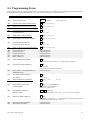
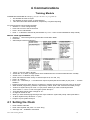
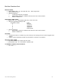
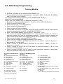
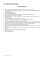
3.7 Menu Mode Programming
Training Module
MENU MODE PROGRAMMING
•
• Zone Programming
• Sequential Learning
• Report Code Programming
• Alpha Programming
• Device Programming
• Relay Programming
• Relay Voice Descriptors
• Custom Index
Answer Yes or No to questions
1 = Yes
0 = No
• System Wide & Partition Specific Fields should be completed first
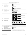
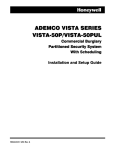
DEVICE PROGRAMMING - CONSOLES
DEVICES (Keypads, 4204, etc.)
Device
Address
Type
Home
Partition
Sounder
Option
Supervised
CF?
00
01
02
03
04
05
06
07
08
09
10
11
12
13
14
15
Device
Address
Type
Home
Partition
Sounder
Option
Supervised
CF?
16
17
18
19
20
21
22
23
24
25
26
27
28
29
30
Type:
0 = device not used
1 = alpha keypad (address 00-30)
3 = RF receiver (address 01-07)
4 = Output Relay module (address 00-15)
5 = Voice Module (address 04 factory set)
Keypad Sounder Options:
00 = no suppression
01 = suppress arm/disarm and entry/exit beeps
02 = suppress chime mode beeps only
03 = suppress arm/disarm, entry/exit and chime mode beeps
A device is anything connected to the Console connections
• Enter Programming
• Press #93
• Enter “0” (4 times) until Device Programming appears, Then enter “1” for Yes
• Device Address Number 01 is already defaulted to an Alpha Console.
Vista 120 Training Guide
31
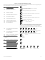
DEVICE PROGRAMMING – Cont.
•
•
•
•
•
•
•
•
•
•
•
Enter Device Address Number (01 – 30).
Press * to move to Device Type
Enter the Required Device (To Program a 6139 Console – Enter “1”)
DEVICE TYPE
DEVICE
ALLOWABLE ADDRESS NUMBERS
1
Alpha Console
01 - 30
1
5800TM
28 - 30
3
RF Receiver
01 - 07
4
Output Relay Module
01 – 15
5
VIP Voice Module
04
Press * to move to Console Partition
Enter the Console’s Home Partition (1-9), Entering a 9 will enable the Console as a Master Console
Press * to move to Sound Option
Enter Console Sounder Option Enter the Device Type “1” for Alpha Console
SOUND OPTION
SOUNDS SUPPRESSED
0
No Suppression
1
Suppress Arm/Disarm & Entry/Exit beeps
2
Suppress Chime mode beeps only
3
Suppress Arm/Disarm, Entry/Exit & Chime beeps
Press * to move to Keypad Global
If Required enter “1” to enable this particular Console to allow Global Arm/Disarm functions.
• If a console is not enabled then a User with Global Arm/Disarming enabled will have to log to each
partition in turn .
Press * to move to Device Address & Program next Device
Continue until all Consoles are programmed in
When finished Enter “00” & “*” to exit Device Address programming
Vista 120 Training Guide
32
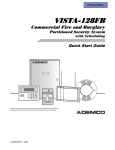
ZONE PROGRAMMING:
ZONE DEFINITIONS FOR ZONES 1-24
devices
Zone
No.
1
Zone
Type
Parti-
DIP DIP
†
RF Trans. Type RPM RPM
tion
(1-8)
RF
(3)
UR
(4)
BR
(5)
left
loop
right
loop
† Enter loop number on module Must be 1
for basic wired, serial numbered, and DIP left loop
Ser. Basic Report
RPM † Wired Code
Zone Information (part numbers) &
Alpha Descriptor (3 words max.)
2
3
4
5
6
7
8
9
•
•
•
•
•
Remain in #93 Menu mode
Answer No “0” until Zone Programming Option is selected
Answer Yes “1” to Zone Programming
Enter 3 digit Zone Number (001 – 128)
Press * to move to Zone Summary
001
ZT
09
P
1
RC
00
IN:
HW:
L
1
ZT
P
RC
In
L
= Zone Type
= Partition
= Report Code
= Input Type
= Response Time or
Loop Number
• Press * to move to Zone Response Type
• Enter required Zone Type
ON IN STAY MODE
Type 01 Entry / Exit Burglary #1
Type 02 Entry / Exit Burglary #2
Type 03 Perimeter Burglary
Vista 120 Training Guide
OFF IN STAY MODE
Type 04 Interior Follower
Type 10 Interior with Delay
24 HOUR ZONE
Type 05 Trouble Day/Alarm Night
Type 06 24 Hour Silent Alarm
Type 07 24 Hour Audible Alarm
Type 08 24-Hour Auxiliary Alarm
Type 09 Supervised Fire
Type 19 24-Hour Trouble
33
ZONE PROGRAMMING Cont.
•
•
•
•
•
Press * to move to Partition
Enter the Partition this Zone belongs to (1 –8).
Press * to move to Report Code – Leave at “0 0” at this time
Press * (3 times) to move to Input Type
Enter the Type of Device being used for this Zone
INPUT TYPE
01
Hardwired Zone
03
Supervised RF (RF)
04
Unsupervised RF (UR)
05
Button RF (BR)
06
Serial Number Polling loop Device (SL)
07
Dip Switch Polling Loop Device
08
Right Loop of Dip Switch Device
• Press * to move to Zone Summary (See above diagram)
• Press * to return to move to “Enter Zone Number” display
• When you have finished programming all zones, Enter 000 as the next zone number & press “*” to quit
•
•
Zone Programming
Then enter “1” (yes) to Exit Menu Mode
Pressing “ # “ allows you to move backwards
Vista 120 Training Guide
34
4. Communications
Training Module
COMMUNICATION DEFAULTS (Program after all Zones are programmed)
• This enables all Zones to report
• This Enables all “Zone Types” to send Restores
• This does not Enable Zones Restores, Supervisory or System Reporting
To Load Contact ID communication defaults
st
• Whilst at 1 Level of Programming
• Press *94 to move to the second level
• Press * 83 to Load Defaults
• Enter “1” to Default to Contact ID (see Defaults on p.134 – 138 of V120a Installation & Setup Guide)
REPORT CODE PROGRAMMING
st
• Whilst at 1 Level of Programming Press #93 & enter Menu Mode
• Press #93
• Select Report Code Programming
•
•
•
•
•
•
•
•
•
•
•
•
•
•
•
Press * to move to Alarm, ID Digit
Answer No “0” to Alarm, ID Digit (These were enabled when the Contact ID Defaults were Loaded)
Answer Yes “1” to Restore, Supv Codes
Enter one Zone from Each Group of 16 Zones (001-016, 017-032, etc)
Press * to continue
Enter a “01” followed by a “*” to enable each report required (See above Table) or just press “*” to leave
disabled
Repeat as required for each Group of 16 Zones by entering one Zone from the next group of 16 zones
When finished programming “Restore / Supervisory Codes”, Enter “000” at the Zone number prompt.
To Move to System Group #1 enter a “0” (No) when asked if you wish to Quit Report Menu
Then Answer “1” Yes or “0” No to Program System Group #1
To Enable these reports enter 1st digit as “01”
nd
2 digit can be left as “00”
When you have finished programming these report codes the system will prompt: Quit report Menu?
To Enter System Group #2 Press “1” (Yes)
Program as per System Group #1
4.1 Setting the Clock
•
•
•
Enter Installer Code #63
Enter value required and press * to move along
See Page 142 – Installation Instructions
Vista 120 Training Guide
35
5. End User Functions
Training Module
INSTALLER CODE
• Entered through Address *00
• Installer Code default is 4140
ACCESS CODES & USER DEFINITIONS FOR PARTITIONS 1-3
4-digit
Security
Code
Access
Group 2-digit
0; 1-8 user #
4-digit
Security
Code
Access
Group 2-digit
0; 1-8 user #
Partition 1
Global
Auth.
Arm?
level
open/
close
2-digit
user #
Partition 2
Global
Auth.
Arm?
level
open/
close
2-digit
user #
Partition 3
Global
Auth.
Arm?
level
open/
close
ACCESS CODES & USER DEFINITIONS FOR PARTITIONS 7 & 8
Authority Levels:
Partition 7
Global
Auth.
Arm?
level
open/
close
2-digit
user #
Partition 8
Global
Auth.
Arm?
level
open/
close
NOTES:
1=master (arm, disarm, bypass, and/or modify lower level users)
2=manager (arm, disarm, bypass, and/or modify lower level users)
3=operator A (arm, disarm, bypass)
4=operator B (arm, disarm)
5=operator C (arm, disarm only if system was armed with this code)
6=duress code (arm, disarm, triggers silent panic alarm)
Vista 120 Training Guide
36
End User Functions Cont.
MASTER CODES
• Enter Installer Code + 8 + 002 (User 002-150) + New 4 Digit Code
• Select Authority Level 1
• Select as Required
•
if Open/Close Reports are desired
•
Multi Partition Access to a Partition other than the Users “Home Partition”
•
Select for Global Arm
ADDITIONAL USER CODES
• Master Code + 8 + Users Number (003-150) + New User Code
• Select the Applicable Authority Level
AUTHORITY LEVEL
TITLE
2
Manager
3
Operator A
4
Operator B
5
Operator C
6
Duress Code
• Select as Required
•
Multi Partition Access to a Partition other than the Users “Home Partition”
•
Select for Global Arm
ADVISORY
• To add a New User to 1 Partition only, the console you are entering him from must be logged to that
Partition
• If Multi Access is selected, the New User will reside in a minimum of 2 Partitions
DELETING USER CODES
• Log to the Partition that contains that User Code
• Enter Master Code + 8 + User Number + Master Code
TO REVIEW A USERS CODE CAPABILITY
• User Code + * + *
Vista 120 Training Guide
37
CONSOLE FUNCTIONS
“Disarming” Mode
• User Code + Off (“1” Key)
“Away & Quick Arm” Mode- All points active
•
User Code + Away (“2” Key)
•
# + 2 (Quick Arm)
“Stay” Mode- Interior type zones bypassed
• User Code + Stay (“3” Key)
“Instant” Mode- Interior type zones bypassed with NO Entry Delay
• User Code + Instant (“7” Key)
“Maximum” Mode- All points active with NO entry delay
• User Code + Maximum (“4” Key)
Logging on to Partitions
• User Code + * + partition number (1-8)
Bypassing of Zones
• User Code + Bypass (“6” Key) + Zone No. (001-128) to be bypassed
• Must be logged to specific Partition
Removing Bypass
• User Code + Off (“1” Key)
Chime Mode
• Chime activated by Perimeter Zones (Types 01,03)
• User Code + Chime (“9” Key) to turn on and off
Clearing Alarm Memory
• Code and Off (Twice)
Fire alarm silence
• Press the off key to silence fire siren
Built in User Manual
• By holding down any of the function keys for 5 seconds, a brief explanation of that function scrolls
across the Alpha-numeric display
House ID “Sniffer Test”
• Master code + # + 2 will start sniffer test. The panel will sample the environment looking for other
systems. Any systems found will be displayed on the LCD console.
• Master code + 1 to exit sniffer test mode.
Set time and date
• Installer code + # + 63. Press in desired values and press * to move along.
Vista 120 Training Guide
38
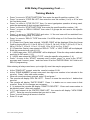
6.1 4208 Hard Wired Expansion Training Module
•
Connect 4208 via twisted pair to the Polling Loop terminals, Positive + 24 and Negative – 25. Observe
Polarity.
•
Set 4208’s DIP switch to select the appropriate block of 8 zones as Serial Numbered Zones
•
•
•
•
•
•
•
•
Use console to enter programming mode: installer code + 8 0 0 0.
Press, #93 to move to “Zone Programming” mode.
Enter 1 to enter “Zone Prog?”.
Enter the 3 digit Zone Number (010 – 128) and press *.
A summary screen showing present configuration will be displayed.
Press * to move to “Zone Response Type
Enter required Zone Type
Press * to move to Partition
Enter the Partition this Zone belongs to (1 –8).
•
Vista 120 Training Guide
39
4208 Hard Wired Expansion Cont.
•
•
•
•
•
•
•
•
•
•
•
•
•
•
•
•
•
•
Press * to move to Report Code
Press * (3 times) to move to Input Type
Enter the Input Type as “06” Serial Number Polling Loop Device
Press * to move to Smart Contact
Leave as “0” (This is used for devices that monitor maintenance signals)
Press * to move to V-Plex Relay
Leave as “0” (This is used for Polling Loop Relays)
Press * to move to Loop #
Enter the Zone’s Loop Number (1 – 8)
Press * to move to Learn S/N
Enter Yes “1”
Enter the 7 digit Serial Number applicable to that Zone or activate the Zone Concerned, or short Zone input
Press * to move to Zone Summary
Press * to move to enter next Zone Number
Repeat above procedure until all required zones are configured, then Enter “000” & “*” at “Zone No.” prompt
to move to “Quit Menu Mode”.
Enter 1 for Yes or 0 for no if more programming is required.
The polling loop itself is a zone (997), and it has a default response type of 05, Trouble by Day/Alarm by
Night. No change is required.
When programming is complete, enter * 9 9 to exit program mode.
For full system information and programming details refer to Vista-120a Installation & Setup Guide.
Vista 120 Training Guide
40
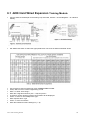
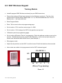
6.2 5882 Wireless Expansion
Training Module
There are three (3) models of 5882:
Ø 5882L will permit up eight (8) additional RF zones.
Ø 5882M will permit up to sixteen (16) additional RF zones.
Ø 5882H will permit up to one hundred & twenty eight (128) additional RF zones.
Note:
Two identical receivers can be used to provide either a greater area of coverage, or
to provide redundant protection.
Zone 64 cannot be programmed for a Wireless zone.
If using two (2) receivers
Each unit must be set to a different device address between 01-07.
Using two (2) receivers DOES NOT increase the number of transmitters the system can
support.
Both receivers must be of the same model.
Receivers should be mounted at least 3 Metres from the Control Panel.
TO INSTALL WIRELESS RECEIVERS
Connect 5882 via the flying lead supplied to terminals 6 (RED), 7 (BLACK), 8 (GREEN) and 9
(YELLOW) of the Vista 120a.
Set 5882’s DIP switch to an unused device address between 01-07.
Use 6139 console to enter programming mode: installer code + 8 0 0 0
Enter *94 to move to 2 nd Level of Programming
Program 1*32 “Receiver Type”, enter 2 (for 5881/5882).
Enter *99 to return to 1 st level of programming
Press # 9 3 to enter Menu Mode.
Press 0 (NO) until “Device Prog?” is displayed, then press 1 (YES).
• Enter the two digit Address Number (01 – 07), as set on the 5882’s Dip Switches
• Press * to move to Device Type
• Enter a Device Type “3” for RF Expander
• Press * to move to RF Expander House ID
If not using a ny RF keypads (5804BD, 5827BD or 5827, press * to continue.
If one, or more than one RF keypads are to be used, enter the two (2) digit House ID (00-31)
as determined by sniffer mode.
If two 5882’s are to be used, follow the same procedure until all outp ut devices have been
programmed, enter 0 0 * to exit “Device Prog?”.
Console will display “Quit Menu Mode?”, enter 1 (Yes) or 0 (No) if more devices need to be
programmed.
Vista 120 Training Guide
41
5882 Wireless Expansion cont….
Training Module
ADDITIONAL WIRELESS PROGRAMMING
1*28 “RF TX Low Battery Sound”. Enter 1 for immediate, or 0 for when disarmed
1*29 “RF TX Low Battery Report Enable”, enter 1 (Yes) or 0 (No) for dialler report.
1*30 “RF Receiver Check-In Interval”, Default 0 6 (Sets 12 hour interval).
1*31 “RF Transmitter Check-In Interval”, Default 1 2 (Sets 24 hour interval).
1*44 “Wireless Keypad Tamper Detect”, enter 1 to enable or 0 to disable.
1*48 “Wireless Keypad Assignment”, enter 1-8 for the partition where the keypad will be
used.
1*49 “Suppress TX Supervision Sounding”, enter 0 to enable audible trouble sounds for
transmitter for check-in failure.
1*57 “5800 RF Button Global Arm”, enter 1 to have the system Arm/Disarm following the
button user’s global arm settings or enter 0 if not.
1*58 “5800 RF B utton Force Arm”, enter 1 to enable the RF button user to force bypass all
faulted zones. When attempting to arm the system, the console will beep once after pressing
the button if any faulted zones are present. If this feature is enabled, the user should then
press the button again within 4 seconds to force bypass those zones and arm the system.
Enter 0 to disable.
For more information see pages 30 to 39 of the Vista 120a Installation and Programming
Guide and the Installation Instructions accompanying the 5882 Receiver.
Vista 120 Training Guide
42
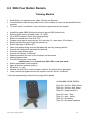
6.3 5804 Four Button Remote
Training Module
•
•
•
•
•
•
•
•
•
•
•
•
•
•
•
•
•
•
•
•
•
•
Each Button is a separate zone. (Max 4 Zones per Remote)
It is advisable to mark the Key with the first zone number, so they can be identified when
required
To avoid “check” conditions, Loop 4 must be programmed into the system
Install & program 5882 Wireless receiver(s) as per 5882 Instructions
Enter program mode. (Installer code + 8 + 000)
Go to #93 and select “Enter Zone programming”
Select an unused zone from 010-128
Program zone type as required (eg. 20= arm stay, 21= arm away, 22= disarm)
Select partition and report code for remote key
Select input type 5 (Button RF)
Learn loop button being used on that particular zone by pressing button
Console will display first transmission received
Press the same button again
Console will display “Confirmed”
Repeat procedure for each of the 4 buttons on the remote
Leave program mode
Proceed to program a user code
- mastercode + 8 + unused user (002-128) + new user code
Select authorisation level required
Open and close reporting (yes/no)
RF button (1 = yes)
Allocate the first of the 4 zone numbers used for the remote when prompted
Loop 4 must be programmed into the system to avoid “check” conditions
* See user programming instructions on page 34 for details
AVAILABLE ZONE TYPES:
Type 06 = 24 Hour Silent Alarm
Type 07 = 24 Hour Aud. Alarm
Type 08 = 24 Hour Aux. Alarm
Type 09 = Supervised Fire
Type 20 = Arm - Stay
Type 21 = Arm – Away
Type 22 = Disarming
Type 23 = No alarm response
Vista 120 Training Guide
43
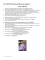
6.4 5804 Bi Directional Wireless Remote
Training Module
•
•
•
•
•
Install & program 5882 Wireless receiver(s) as per 5882 Instructions
Ensure that a House ID has been assigned to the Wireless receiver(s)
Terminate the 5800TM on the console bus. The 5800TM should be a minimum distance
of 3 metres away from the panel to stop any interference.
The 5800TM must be programmed as an unused address within the range of 28 through
to 30. Cut the red jumper for an address of 28, white jumper for 29 and both for 30.
Enter program mode.
Device Programming:
• Go to location #93 and select Device programming.
• Select the address of the 5800TM (28-30) and enable it as an “Alpha Console”.
• Exit “Device Programming” (00 = Quit).
Zone Programming:
• “Enter Zone programming”
• Select an unused zone from 010-128
• Program zone type as required (eg. 20= arm stay, 21= arm away, 22= disarm)
• Select partition and report code for remote key
• Select input type 5 (Button RF)
• Learn loop button being used on that particular zone by pressing button
• Console will display first transmission received
• Press the same button again
• Console will display “Confirmed”
• Repeat procedure for each of the 4 buttons on the remote
• To avoid “check” conditions, Loop C must learnt into the system.
• Leave program mode
User Code Programming:
• Proceed to program a user code
- mastercode + 8 + unused user (002-128) + new user code
• Select authorisation level required
• Open and close reporting (yes/no)
• RF button (1 = yes)
• Allocate the first of the 4 zone numbers used for the remote when prompted
• Loop 4 must be programmed into the system to avoid “check” conditions
•
* See user programming instructions on page 34 for details.
Vista 120 Training Guide
44
5804 Bi Directional Remote Programming Cont……
House ID Programming:
•
•
•
•
•
•
Programming of the house ID into the 5804BD is required to identify the 5804BD into the
system.
Hold down the A,B and C until the green and red LED’s blink alternately.
Enter the house ID by using the “A’ button as the tens digit and the “B” button to the ones
digit.
Accept the entry by pressing the “D” button.
Exit house ID programming mode.
The 5804BD must now be assigned to a user (In the same manner as the 5804). Assign
the first zone of the 5804BD as the “RF Key” when prompted in user programming.
AVAILABLE ZONE TYPES:
A
B
C
D
Vista 120 Training Guide
Type 06 = 24 Hour Silent Alarm
Type 07 = 24 Hour Aud. Alarm
Type 08 = 24 Hour Aux. Alarm
Type 09 = Supervised Fire
Type 20 = Arm - Stay
Type 21 = Arm – Away
Type 22 = Disarming
Type 23 = No alarm response
45
6.5 5827 Wireless Keypad
Training Module
•
Install & program 5882 Wireless receiver(s) as per 5882 Instructions
•
Ensure that a House ID has been assigned to the Wireless receiver(s). Test for other
systems with ID Sniffer Mode (Mastercode + # + 2). Recommended test time 2 hours.
Mastercode + 1 will end sniffer test.
•
Enter Program Mode
•
Enter * 94 to move to the next programming page.
•
Go to location 1*32 to set the receiver type 2 = 5881.
•
Go to location 1*48 to assign the 5827 to the partition as required.
•
*99 back to previous programming page.
•
Go to location #93 select “Device” programming. Enter the address number as set on the
receiver. Enable that device as a type 3 (RF Expander). At the next prompt assign the
house code as decided after sniffer mode. (See example 1)
•
Exit program mode.
•
Adjust the dip switches on the 5827 to suit the house ID with the batteries disconnected.
•
User codes are unable to be programmed via the 5827 wireless keypad.
EXAMPLE 1
ON
OFF
16
8
4
2
1
(Binary Programming)
8 on = 8
Vista 120 Training Guide
46
6.6 5827 Bi Directional Wireless Keypad
Training Module
•
•
•
•
•
•
•
•
•
Install & program 5882 Wireless receiver(s) as per 5882 Instructions
Ensure that a House ID has been assigned to the Wireless receiver(s)
Terminate the 5800TM on the console bus. The 5800TM should be a minimum distance
of 3 metres away from the panel to stop any interference. The 5800TM must be
programmed as an unused address within the range of 28 through to 30. Cut the red
jumper for an address of 28, white jumper for 29 and both for 30.
Enter program mode (Installer code + 8 + 0 + 0 + 0).
Go to location #93 and select Device programming.
Select the address of the 5800TM (28-30) and enable it as an “Alpha Console”.
Exit “Device Programming” (00 = Quit).
Go to 1* 48 and select which partition the keypad will operate (0 = disable).
Exit programming mode *99.
A number of system functions must be programmed into the 5827BD.
• After the battery is fitted to the 5827BD, power the unit up by pressing the * key. The
yellow LED should blink.
• Enter console programming mode by depressing 1 and 3 simultaneously. The red and
green LED should blink.
• The systems 4 digit Master Code must be programmed by pressing
Ø 8 then the 4 digit code and #
• For Quick Key function of Arm and Chime but not Disarm enter
Ø 2 then the 4 digit code and #.
• The systems House ID must be programmed by entering
Ø * 9 and then the 2 digit House ID then #.
• The systems RF type must be programmed by entering
Ø * 5 8 for 5800 and then #.
• Exit program mode by entering
Ø * #.
Vista 120 Training Guide
47
6.7 4285 Voice Interactive Phone Module
Training Module
•
•
•
•
•
•
•
•
•
•
•
•
Terminate 4285 on to console bus.
Connect the panel to the “C Com” jack on the 4285 line interface using the cable supplied
with the 4285.
Take the cable previously used for the “mode 3” connection, and connect directly to “Wall”
jack on the 4285.
Enter program mode.
Go to location *20 to program the Voice Module access code. The first digit must be
programmed within the range of 01-09 and the second digit must be a *(11) or #(12).
Go to location *44 and set ring detect to 1-14 rings or 15 = answering machine defeat.
Go to location #93 and select “Device Prog”.
The VIP must be assigned to address “4”.
Select the device type “5”, Voice Module.
Select the master partition that the users with access to are assigned to.
Exit program mode.
To access the VIP either pick up the touch tone phone on the premises and dial the phone
code or dial up the system as programmed in location *44.
Vista 120 Training Guide
48
6.8 4204 Relay Programming
Training Module
•
•
Set 4204’ DIP switch for an unused device address 01-15.
Connect 4204 via the flying lead supplied to terminals 6 (RED), 7 (BLACK), 8 (GREEN)
and 9 (YELLOW) of the Vista50P.
Use 6139 console to enter programming mode: installer code + 8 0 0 0
Press # 9 3 to enter Menu Mode.
Press 0 (NO) until “Device Prog?” is displayed, then press 1 (YES).
• Enter the two digit Address Number (01 – 15), as set on the 4204’s Dip Switches
• Press * to move to Device Type
• Enter a Device Type “4” for Output Device
• Press * to move to Supervised CF
• Press * to move to Device Address
• If more than one 4204 is to be used, follow the same procedure until all output devices
have been programmed, enter 0 0 * to exit “DEVICE PROG?”
• Enter * until console displays “RELAY PROG?”, then press 1 (Yes)
• The console will display “ENTER RELAY No.”, enter the relay number 1-4. This is a
reference number only, used for identification purposes. The actual module address and
relay number on the module is programmed in the last two prompts. Press * to continue.
• The console will display a summary START screen.
• Press * and the console will display a summary STOP screen.
• Press * to move to “RELAY ACTION” then enter 0 = not used, 1 = close for 2 secs, 2 =
stay closed to 3 = pulse on/off.
• Press * to move to “START EVENT” then enter 0 = not used, 1 = alarm, 2 = fault, 3 =
trouble or 4 = restore.
• Press * to move to “START ZN LIST” then enter the zone list number (1 to 8) or 0 is a
zone list is not being used.
• Press * to move to “START ZN TYP” then, if a zone type/system operation is being used,
enter the appropriate 2-digit code as listed below.
Choices for Start/Stop Zone
Types
00 = No Response (Not used)
01 = Entry/Exit # 1
02 = Entry/Exit # 2
03 = Perimeter
04 = Interior Follower
05 = Trouble Day/Alarm Night
06 = 24Hr Silent
07 = 24Hr Audible
08 = 24Hr Aux
09 = Fire Alarm or Trouble
Choices for Start/Stop System
Operation
20 = Arming Stay
21 = Arming Away
22 = Disarming (Code+Off)
31 = End of Exit Time
32 = Start of Entry Time
34 = Code + # + 71 Key Entry
35 = Code + # + 72 Key Entry
36 = **At Bell Timeout **
37 = 2 Times Bell Timeout
38 = Chime
10 = Interior w/Delay
39 = Fire Alarm
23 = No Alarm response
(for output relay activation,
such as for access control)
40 = Bypassing
Vista 120 Training Guide
41 = **AC Power Fail
42 = **System Battery Low
43 = Communication Failure
44 = RF Low Battery
45 = Polling Loop Failure
51 = RF Receiver Failure
52 = Kissoff
54 = Fire Zone Reset
55 = Disarm + 1
56 = XX Minutes (enter XX in field 1*74 Stop
condition Only)
57 = YY Seconds (enter YY in field 1*75 Stop
condition Only)
58 = Duress
*** Or at Disarming, whichever occurs earlier)
49
4204 Relay Programming Cont……
Training Module
•
•
•
•
•
•
•
•
•
•
•
•
Press * to move to “START PARTITION” then enter the specific partition number (1-8).
Press * to move to “STOP ZN LIST” then enter the zone list number (1 to 8) or 0 if a zone
list if not being used.
Press * to move to “STOP ZN TYP” then, if a zone type/system operation is being used,
enter the appropriate 2-digit code as listed above.
Press * to move to “STOP PARTITION” then enter the specific partition number (1-8).
Press * to move to “RELAY GROUP” then enter 0 if groups are not used or the specific
group (1 to 8).
Press * to move to “RESTRICTION” and enter 1 if the end user will be restricted from
accessing this relay group, if no enter 0.
Press * to move to “RELAY TYPE” then enter 1 for 4204 relays or 2 for Power Line Carrier
(X-10) device.
If 2 (Power Line Carrier) was entered, “HOUSE CODE” will be displayed. Enter the House
Code by keying 00 for A, 01 for B, 02 for C, 03 for D, 04 for E, 05 for F, 06 for G, 07 for H,
08 for I, 09 for J, 10 for K, 11 for L, 12 for M, 13 for N, 14 for O or 15 for P.
If 2 (PowerLine Carrier) was entered at “RELAY TYPE”, a “UNIT CODE will be displayed.
Enter the numerical unit code (01-15)
If 1 (4204) was enter, “ECP ADDRESS” will be displayed. Enter the relay module address
as set by its DIP switch (1-15).
If 1 (4204) was entered at “RELAY TYPE”, enter the specific relay number (1-4).
Press * to move to the “START” summary and if correct, press * to move to the “STOP”
summary and if correct, press * and then enter 00 at the “ENTER RELAY No” field to exit
RELAY programming.
After entering all relay menu items, up to eight (8) zone lists may be programmed.
•
•
•
•
•
•
•
•
•
At the “ZONE LIST” prompt, enter the zone list number 01-08.
At the “ZONE NUMBER” prompt, enter each two digit zone number to be included in the
zone list. Press * after each zone number.
When all zones have been entered, enter 0 0 and press *.
The console will display “DEL ZN LIST?”. Press 0 to save the zone list or 1 deletes that
zone list.
The console will display “DLETE ZONE?” Press 1 to delete one or more zones in that
zone list. Enter 0 if no changes are necessary.
If 1 is entered the console will display “ZONE TO DELETE?”. Enter each zone number to
be deleted; press * after each number.
If 0 0 was entered at the “ENTER ZONE LIST”, the console will display “VIEW ZONE
LIST?”. Enter the zone list number that you wish to view.
Press * to scroll through all zones in that list.
Enter 0 0 to quit.
Vista 120 Training Guide
50
6.9 Garage Door Setup
Training Module
•
•
•
•
•
•
•
•
•
•
•
•
•
•
•
•
•
Learn in zone required to trigger the relay driving the garage or roller door.
Go to #93 and select “Device Programming”. Program the relay module address as set on
its dip switches.
Exit “device Programming”.
Select “Relay Programming”.
Select the relay number you wish to program to pulse to garage door motor
Select the “Action” – Closed for 2 seconds.
Select the start event – Fault, followed by the zone list that you wish to assign the zone
from the 5804 to.
Select the partition that the start function will occur in.
No “Stop” programming is required as the relay is closed for 2 seconds
No further programming is required in relay programming.
After all relays have been programmed, upon entering “00” at the “ENTER RELAY NO”
prompt, you will be asked to enter a “Zone List”. If a zone list number was used to start or
stop relay, you must define the zone that belongs to that zone list as follows:
Enter “Zone List” number assigned to trigger the door relay.
Enter 2 digit entries followed by * for all zones that will be used to open the door. Finish
with 00*.
Enter 2 digit entries followed by * for all zones that will be used to open the door. Finish
with 00*.
Make sure that the 5804 has been assigned to a user.
Exit program mode.
Code + off the system.
Vista 120 Training Guide
51
7. Servicing Tips
Training Module
POWER CONSIDERATIONS:
The Vista 120 has a:
12V 750mA Auxiliary power output
12V 2.8A Alarm sounder output
128mA Polling loop output
If Power is of Concern:
Please refer to the current drain Work sheets on Page 60 of the Installation Instructions
If an additional power supply is required, ensure there is a ‘common ground’ connection
between the power supply and the control
SUPERVISORY ZONES - (see Page 68 Installation Manual)
Zones 601 – 696
Relay Zones – To supervise relay, use the Zone programming menu to enter a response type
5 or 19 for that Relay’s zone number
Zones 800 - 830
ECP device Supervisory Zones (includes Consoles, wireless receivers, VIP Module, relay
modules) programmed through Device Addresses.
Zone 988 – 2nd Receiver not receiving signals
Zone 990 – 1st Receiver not receiving signals
Zone 997 – Polling Loop overload
Zone 995 – 1 + * panic (A Key)
Zone 996 – 3 + # panic (C Key)
Zone 999 – * + # panic (B Key)
CHECK CONDITIONS:
•
Fire zones: Indicates an Open circuit
•
Wireless zones: May be caused by some change in the environment preventing the
receiver from receiving signals from that particular sensor OR that the transmitter’s tamper
has been activated
LOW BATTERIES:
•
Low battery & zone number indicates a low battery in the wireless sensor displayed
•
Low battery & “00” zone number indicates a low battery in a 5827 or 5827BD wireless
console.
•
Low battery & no zone number indicates the system’s main battery is weak & the System
may be difficult to disarm, if in alarm
Vista 120 Training Guide
52
Servicing Tips Cont.
COMM FAILURE (FC) - A communication failure has occurred
OPEN CIRCUIT (OC) - The keypad is not receiving signals from the control & sees an open
circuit
VOLTAGES
- A/C volts should be 16.5VAC
- D.C. Volts across the battery leads (no battery fitted) should be 13.6 - 13.8 Dc
Need More Help?
Call our
Technical Support Team
Phone: 1800 220 345
Vista 120 Training Guide
53