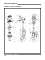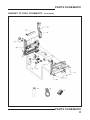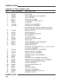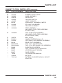
1
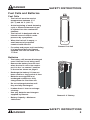
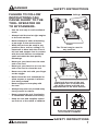
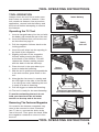
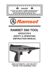
DANGER
READ AND OBEY ALL SAFETY AND OPERATING
INSTRUCTIONS BEFORE OPERATING TOOL.
RAMSET T2 TOOL
OPERATOR’S
SAFETY & OPERATING
INSTRUCTION MANUAL
GAS POWERED, LOW VELOCITY
PISTON TYPE FASTENING TOOL
SAFETY INTRODUCTION
DANGER
DANGER
THIS TOOL IS TO BE USED ONLY BY PROPERLY TRAINED
OPERATORS. ATTEMPTING TO HANDLE OR OPERATE THE T2 GAS
POWERED TOOL WITHOUT PROPER TRAINING CAN RESULT
IN SERIOUS INJURY TO THE OPERATOR OR BYSTANDERS.
! Read, understand and follow the instructions in
the tool manual before attempting to use the tool.
! Operators and Bystanders must wear eye and
hearing protection.
! Never close tool with hand over the fastener loading
end of the tool. A serious hand injury from penetration
by the piston or fastener could result.
! The gas in fuel cells is under pressure and the gas
is flammable.
! Do not open, puncture or burn fuel cells.
! Store fuel cells in a well ventilated area, at temperatures
below 50° C (122° F) and out of the sunlight.
! Keep fuel cells away from flames, sparks and heat.
! Do not attempt to recharge, refill or recycle fuel cells.
! Never operate the T2 tool if flammable or explosive
materials are nearby.
DANGER
Just as no one can merely read a book about driving an automobile and then hope
to drive one safely, no one should attempt to use the T2 gas powered tool without
adequate, competent personal instruction.
No automobile instruction book or instructor can forewarn a learner against all possibilities
and emergencies, nor can printed material detail all possible conditions surrounding the
use of Ramset tools and products.
Responsibility for the safe and proper use of this tool rests with the tool user
and the employer.
SAFETY INTRODUCTION
2
DANGER
TABLE OF CONTENTS
SAFETY INTRODUCTION 2
CONTENTS 3
SAFETY INSTRUCTIONS 4-7
FASTENING APPLICATIONS 8
TOOL OPERATING INSTRUCTIONS 9
PARTS SCHEMATIC
10-11
PARTS LIST
12-13
SERVICING/TROUBLESHOOTING 14
WARRANTY 15
TABLE OF CONTENTS
3
DANGER
SAFETY INSTRUCTIONS
Preparation For Fastening
Acceptable Base Materials
The gas powered T2 tool is suitable for
use in the following base materials only:
• Poured Concrete
• Structural Steel
Solid Concrete and
Precast Concrete
• Concrete Block and Horizontal Joints
in Brick or Masonry Walls
Never attempt to fasten into any other
type of material. Fastening into other
materials can cause blindness or other
serious injury.
Never attempt to fasten into very hard
or brittle materials such as cast iron,
tile, glass, or rock of any type. These
materials can shatter, causing the fastener
and/or base material fragments to fly
free and cause serious injury to the tool
operator and others.
Structural Steel
Solid or Hollow
Block
Never fasten into any base material that
does not pass the Center Punch test.
Failure to assure the suitability of the
base material can result in serious injury
to the eyes or other body parts.
Horizontal Joints
only in Brick Walls
Center Punch Test
ALWAYS WEAR SAFETY GOGGLES
WHEN PERFORMING THIS TEST.
1. Always check the material being
fastened into for hardness before
attempting any fastening operation.
2. Using a fastener as a center punch,
strike the fastener against the work
surface using an average hammer
blow and check the results.
SAFETY INSTRUCTIONS
4
Center Punch Test Results
1. If the fastener point is flattened,
the material is too hard for a
powder actuated fastening.
2. If the fastener penetrates the
material easily, the material is
too soft.
3.If the material cracks or shatters,
the material is too brittle.
4. If the fastener makes a small
indentation into the material, the
material is suitable for fastening.
DANGER
DANGER SAFETY INSTRUCTIONS
Fuel Cells and Batteries
Fuel Cells
• The fuel cell must be used at
temperatures between -5° C
(23° F) and 49° C (120° F).
• At the beginning of each fastening
cycle, a measured amount of gas
is injected into the combustion
chamber.
• The fuel cell is designed with an
internal reservoir that is under
pressure by a propellant.
• When the fuel cell is empty, a
small amount of propellant
remains inside the cell.
• For safety and proper tool functioning
it is important that only Ramset
supplied fuel cells be used in the
T2 tool.
Ramset Fuel Cell
Batteries
• The battery will become discharged
even if the tool is not being used.
• Remove the battery from the tool
when the tool is not to be used or
put it in the “no contact” position
in the tool as shown on page 6.
• Recharge the battery if it has not
been used for a long period of time.
• Batteries are supplied in an
uncharged condition so fully
charge them for first time use.
• Do not recharge batteries until
they are fully discharged.
• It takes about 1 hour to recharge
a battery.
• Use only batteries and chargers
supplied by Ramset.
• Battery Capacity—Maximum
1200 shots.
DANGER
Ramset 6 V. Battery
SAFETY INSTRUCTIONS
5
DANGER
SAFETY INSTRUCTIONS
Installing the battery
• Insert the battery into the tool
as shown on the right with the
clip toward the rear.
Battery is shown in the “no contact”
position. Push it fully down to lock it
in place.
• Note the LED light on the right
side of the handle. After installing
the battery:
- If the light flashes green the
tool is powered.
- If the light flashes red the battery requires charging.
- If the light is solid green and
the fan is running, the tool is
ready to use.
- If the light is solid red and the
fan is not on the battery needs recharged.
Turn and remove cap
Installing the fuel cell
• There is a cap located on the rear of
the tool handle that covers the fuel
cell. Twist the cap 1/8 turn clockwise
and remove it.
• Insert the fuel cell, nose first, all the
way into the recess.
• Replace the cap by lining up the
lugs on the cap with the notches in
the tool handle, push the cap in and
twist it 1/8 turn counterclockwise
to the locked position.
SAFETY INSTRUCTIONS
6
Insert fuel cell into recess
DANGER
DANGER SAFETY INSTRUCTIONS
FAILURE TO FOLLOW
INSTRUCTIONS CAN
CAUSE INJURY TO THE
TOOL OPERATOR OR
TO BYSTANDERS.
• Use the tool only in well ventilated
areas.
• Always hold the tool at right angles
to the work surface.
• Never attempt to make a fastening
at an angle to the work surface.
• While the tool can be used in any
position (floor, wall or ceiling) it is
important to have both the nose of
the tool and support foot in contact
with the work surface to minimize
spall and make the best quality
fastenings.
Ceilings
Walls
Floors
The T2 tool may be used in
any position.
• Never put your hand over the nose
end of the tool.
• Never put your hand on or over the
end of the tool to close the tool.
• Never carry the tool with your finger
on the trigger.
• Never leave the tool unattended or
allow anyone to operate it without
first being trained.
• Never engage in horseplay with
the tool.
• Always keep the tool pointed away
from yourself or others.
90°
Keep both the nose of the tool
and support foot in contact with
the work surface and hold tool
perpendicular to the work surface.
• Never operate the tool if explosive
or flammable materials are nearby.
• Keep the tool and supplies locked
up and out of the reach of children.
Keep tool locked up and
out of reach of children
DANGER
SAFETY INSTRUCTIONS
7
FASTENING APPLICATIONS
3"
MIN.
FASTENING APPLICATIONS
Your T2 tool can be used for a wide
range of fastening needs in a variety of
base materials. Reading and following
these important fastening guidelines will
help you get the best results from your
tool and fasteners, as well as help you
perform these fastening operations
safely and effectively.
T2 fastenings are permanent
fastenings so attempting to remove
a fastener from concrete or steel
may result in a serious injury.
3"
MIN.
PENETRATION - THIN GAUGE
METAL TO CONCRETE
Fastening to Concrete
When fastening into concrete, always
maintain a minimum spacing of 3”
between fastenings and 3” from any
free edge. Concrete thickness should
be at least three times the intended
penetration depth into the concrete.
Driving fasteners too close to an
edge or too close to each other
can cause the concrete edge to
fail or fasteners to fly free.
3" MIN.
SPACING - THIN WOOD
STRIP TO CONCRETE
Fastening to Concrete
Block or to Masonry Walls
Take care to observe a 3” edge distance
to avoid cracking the block and over
penetration of the fastener to avoid a
loss of holding value. Fastenings may
also be made into the horizontal joint
but not into the vertical joint.
3"
MIN.
3"
3" MIN.
MIN.
3"
1/2"
MIN.
1/2"
MIN.
MIN.
1-1/2"
MIN.
1-1/2"
MIN.
Fastening to Steel
Your T2 tool can be used for fastening
on the flat surfaces of structural steel.
When fastening into steel, always maintain
a minimum spacing of 1-1/2” between
fastenings and 1/2” from any edge.
FASTENING APPLICATIONS
8
SPACING
STEEL TO STEEL
3" MIN.
TOOL OPERATING INSTRUCTIONS
TOOL OPERATION
Insert battery
Always check the tool first to make sure
that it does not contain a fastener. If the
tool contains a fastener from a previous
application, remove both the battery and
the fuel cell before attempting to remove
the fastener.
Operating the T2 Tool
1. Insert a charged battery into the tool with
the battery clip toward the rear of the tool.
2. Insert the Ramset fuel cell into the tool
as described on page 6.
Insert
fuel cell
3. Pull the magazine follower back to the
locking position.
4. Insert the nail strips into the opening in
the back of the magazine.
5. Slightly pull back on the magazine
follower while pressing the button
at the back of the follower. This will
release the follower making contact
with the back of the last nail strip.
6. Place the tool in the spot where you
want to make the fastening.
7. With the tool in position and perpendicular
to the work surface; press down on the
tool.
Insert
fastener
8. Note that the fan motor is running and
the LED light on the side of the handle
is a solid green color indicating the tool
is ready to make a fastening.
9. Pull the trigger to make the fastening.
10.The tool is ready for the next fastening.
To avoid overheating the tool do not
hold your hand over the air intake
section on the top end of the tool.
Removing The Fastener Magazine
On occasion the fastener magazine may
need to be removed to clear a fastener
jam. To do so, unscrew the knob at the
rear of the tool. Then press the knob. Slide
the magazine rearward to remove it from
the tool.
90°
Hold tool perpendicular
In contact with work surface
Knob
TOOL OPERATING INSTRUCTIONS
9
PARTS SCHEMATIC
RAMSET T2 TOOL SCHEMATIC
PARTS SCHEMATIC
10
RAMSET T2 TOOL SCHEMATIC
PARTS SCHEMATIC
(continued)
PARTS SCHEMATIC
11
PARTS LISTS
RAMSET T2 TOOL PARTS LISTS
KEY
PART NUMBER
1
336920
2
336900
3
B0060A
4
339000
5
B0070
6
B0061A
7
B0040
8
7505164
9
900525A
10
401356
11
900470
12
401355
13
404601
14
B0078
15
403992
16
403167
17
B0044A
17
B0057
18
339010
19
333180
21
337700
22
336510
23
333220
24
B0038
25
B0178
26
333250
27
B0068
28
B0031A
28A
B0034A
29
B0053
31
B0042
32
B0054A
33
B0037A
35
B0105
PARTS LIST
12
DESCRIPTION
GRILL CAP
AIR FILTER
CAP SCREWS M5-30 W/WASHER
CAP ASSEMBLY
SPARK PLUG WIRE
PC BOARD SCREWS, M4-12
PC BOARD
SPARK PLUG ASSEMBLY
FAN MOTOR ASSEMBLY
(INCLUDES FAN, MOTOR SLEEVE, MOTOR MOUNT, RETAINING RING AND FAN BLADE)
MOTOR SLEEVE
MOTOR MOUNT
MOTOR RETAINING RING
HEAD SWITCH
CYLINDER HEAD
O-RING, CYLINDER HEAD
FAN BLADE
CAGE ASSEMBLY AND BUMPERS
CAGE SCREWS M4-6
SHEAR BLOCK KIT
(CONSIST OF: SHEAR BLOCK, (2) - M5 T-NUTS, (2) - M5-12 SCREWS)
TIE BAR ASSEMBLY - W/SCREWS
WORK CONTACT ELEMENT
HOUSING BODY ASSEMBLY
RUBBER DEFECTOR ASSEMBLY
AIR DAM
COMBUSTION CHAMBER ASSEMBLY
COMBUSTION CHAMBER STOP ASSEMBLY
PISTON STOP RETAINING RING
PISTON ASSEMBLY
PISTON RINGS (PKG of 2)
BUMPER
SLEEVE O-RING
GAS DUCT ASSEMBLY
CHAMBER SPRINGS (PKG of 2)
SECURITY STOP
PARTS LIST
RAMSET T2 TOOL PARTS LISTS (continued)
KEY
PART NUMBER
37
334020
38
337440
39
333380
40
404619
41
404490
42
404385
43
B0134
45
010422
46
333450
47
333460A
49
333480A
51
336870
53
B0062A
54
010900
55
B0144
56
EM150330
57
EM150340A
—
B0058
—
B0072
—
B0073
—
B0057
*
T2OM
*
334000
*
7505142
DESCRIPTION
BATTERY SUPPORT
RUBBER HANDLE GRIP
KNOB ASSEMBLY
INSULATOR
TRIGGER SWITCH
LIGHT CONDUIT
SPARK UNIT ASSEMBLY, MEFI-R
EFI JUNCTION BOARD
TRIGGER ASSEMBLY
FEED ASSEMBLY
(INCLUDES: FUEL FEED ASSEMBLY
& FEED TUBE)
FUEL INJECTION ASSEMBLY
(INCLUDES: FUEL FEED ASSEMBLY
& FUEL FEED TUBE)
BELT HOOK
HANDLE SCREWS (pkg of 5)
LEFT/RIGHT SIDE HANDLE ASSEMBLY
REAR FOOT ASSEMBLY
FUEL CELL CUP BRACKET
FUEL CELL RETAINING CUP ASSEMBLY
GUIDE BLOCK SCREW
FUEL CONNECTOR SCREW M4-8
UPPER EXHAUST SCREW
CAGE SCREW
T2 OPERATORS MANUAL
BATTERY
BATTERY CHARGER W/WALL MOUNT ADAPTOR
PARTS LIST
13
SERVICING/TROUBLESHOOTING
FOR SERVICING REQUIRED BUT NOT LISTED IN THIS MANUAL,
PLEASE CONTACT YOUR LOCAL DISTRIBUTOR
Filters and Battery Contacts
Cleaning the filters and battery contacts on a regular
basis will help make your tool work more efficiently.
To clean the filters
• Remove the cover and the filters.
• Lightly tap the filters to remove any dust.
• Replace the filters if damaged.
• Replace the filters and the cover.
To clean the battery contacts
• Periodically wipe contacts with a dry, soft cloth.
• Should they show corrosion, clean with a piece of
very fine emery cloth and clean with a dry cloth.
TROUBLESHOOTING
Tool does not work
- LED light is off - No battery in tool - Install battery
- LED flashes red - Battery completely discharged - Charge battery
- LED is red - Battery power is too low - Recharge battery
- LED is green - Fuel cell is exhausted - Put in new fuel cell
Fan stops after the trigger is pulled
and LED is green
- Call your local distributor for service
Tool firing is not consistent and
LED is green
- Fuel cell is exhausted - Put in a new fuel cell
Fasteners are not completely set - Fuel cell is exhausted - Filters are too dirty - Base material is too hard - Put in a new fuel cell
- Clean/replace filters
- Consult distributor
Tool makes low sound
- piston stays down
- no fastening made
- LED is green
- Consult your local distributor
Tool is sluggish and overheats
- Filters are too dirty Fan is on but the
tool does not fire
SERVICING/TROUBLESHOOTING
14
- Clean/replace filters
WARRANTY
T2 TOOL WARRANTY AND LIMITATIONS
Ramset warranty that new T2 power
fastening tools, parts and accessories
will be free from defects in material
and workmanship for the period shown
below, after the date of delivery to the
original user.
TWO-YEAR WARRANTY
A two-year warranty will apply to
all parts, except those listed below
as normal wearing parts, or parts
which are specifically covered by
an extended warranty.
SIX-MONTH WARRANTY
A six-month warranty applies to the
following parts, which are considered
normal wearing parts:
• Bumper
• Piston Assembly
• O-Rings
• Piston Rings
WARRANTY STATEMENT
Ramset’s sole liability hereunder will be
to replace any part or accessory which
proves to be defective within the specific
time period. Any replacement part or
accessory provided in accordance with
this warranty will carry a warranty for
the balance of the period of warranty
applicable to the part it replaces.
This warranty does not apply to part
replacement required due to normal
wear.
This warranty is void as to any tool
which has been subjected to misuse,
abuse, accidental or intentional damage,
use with fasteners, fuel, battery, or battery
chargers not meeting Ramset specification,
size, or quality, improperly maintained,
repaired with other than genuine T2
replacement parts, damaged in transit
or handling, or which, in Ramset’s
opinion, has been altered or repaired in
a way that affects or detracts from the
performance of the tool.
RAMSET MAKES NO WARRANTY,
EXPRESSED OR IMPLIED, RELATING
TO MERCHANTABILITY, FITNESS, OR
OTHERWISE, EXCEPT AS STATED
ABOVE and the liability AS STATED
ABOVE AND AS ASSUMED ABOVE
is in lieu of all other warranties arising
out of, or in connection with, the use
and performance of the tool, except
to the extent otherwise provided by
applicable law.
RAMSET SHALL IN NO EVENT BE
LIABLE FOR ANY DIRECT, INDIRECT,
OR CONSEQUENTIAL DAMAGES,
INCLUDING, BUT NOT LIMITED TO
DAMAGES WHICH MAY ARISE FROM
LOSS OF ANTICIPATED PROFITS
OR PRODUCTION, SPOILAGE OF
MATERIALS, INCREASED COST OF
OPERATION OR OTHERWISE.
Ramset reserves the right to change
specifications, equipment, or designs
at any time without notice and without
incurring obligation.
WARRANTY
15
FOR TOOL REPAIR SERVICE CONTACT YOUR LOCAL
AUTHORIZED RAMSET DISTRIBUTOR OR TO FIND
YOUR NEAREST RAMSET TOOL REPAIR CENTER
VISIT OUR WEB SITE AT WWW.RAMSET.COM
OR CALL 800-241-5640
Concrete Fastening Systems
Glendale Heights, IL 60139
800-RAMSET6 (1-800-726-7386)
www.ramset.com
Buy with Confidence...
Buy From Your Authorized Distributor
AN ILLINOIS TOOL WORKS COMPANY
© ILLINOIS TOOL WORKS 2008
PRINTED IN THE U.S.A.
REVISED 11/08
Form No. SM-T2-11/08